

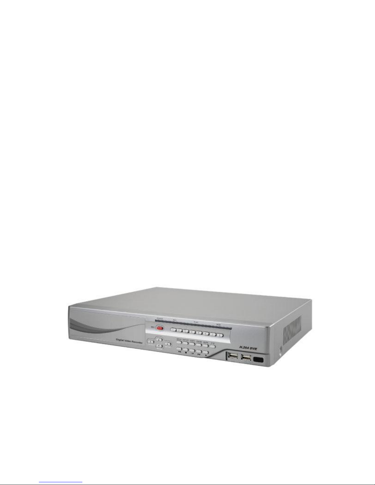
Hunt Electronic HBD-09EE User Manual
USER MANUAL
9 CHANNELS HYBRID
DIGITAL VIDEO RECORDER
2
INSTRUCTION MANUAL
To obtain the best performance and ensure device function correctly, please read this instruction manual carefully and
completely.
FCC Compliance
USER-INSTALLER CAUTION: YOUR AUTHORITY TO OPERATE THIS FCC VERIFIED EQUIPMENT
COULD BE VOIDED IF YOU MAKE CHANGES OR MODIFICATIONS NOT EXPRESSLY APPROVED BY THE
PARTY RESPONSIBLE FOR COMPLIANCE TO PART 15 OF THE FCC RULES.
NOTE: THIS EQUIPMENT HAS BEEN TESTED AND FOUND TO COMPLY WITH THE LIMITS FOR A
CLASS A DIGITAL DEVICE, PURSUANT TO PART 15 OF THE FCC RULES. THESE LIMITS ARE
DESIGNED TO PROVIDE REASONABLE PROTECTION AGAINST HARMFUL INTERFERENCE WHEN THE
EQUIPMENT IS OPERATED IN A COMMERCIAL ENVIRONMENT. THIS EQUIPMENT GENERATES, USES,
AND CAN RADIATE RADIO FREQUENCY ENERGY AND IF NOT INSTALLED AND USED IN
ACCORDANCE WITH THE INSTRUCTION MANUAL, MAY CAUSE HARMFUL INTERFERENCE TO RADIO
COMMUNICATIONS.
OPERATION OF THIS EQUIPMENT IN A RESIDENTIAL AREA IS LIKELY TO CAUSE HARMFUL
INTERFERENCE IN WHICH CASE THE USER WILL BE REQUIRED TO CORRECT THE INTERFERENCE AT
HIS OWN EXPENSE.
THIS CLASS A DIGITAL APPARATUS MEETS ALL REQUIREMENTS OF THE CANADIAN
INTERFERENCE-CAUSING EQUIPMENT REGULATIONS.
WARNINGS, CAUTIONS & COPYRIGHT
WARNING
TO REDUCE THE RISK OF FIRE OR ELECTRIC SHOCK, DO NOT EXPOSE THIS PRODUCT TO RAIN OR
MISTURE.
DO NOT INSERT ANY METALLIC OBJECT THROUGH VENTILATION GRILLS.
CAUTION
Explanation of Graphical Symbols
The lightning flash with arrowhead symbol, within an equilateral triangle, is intended to alert the
user to the presence of insinuated "dangerous voltage" within the products enclosure that may be of
sufficient magnitude to constitute a risk of electric shock to persons.
The exclamation point within an equilateral rhombus is intended to alert the user to the presence of
important operating and maintenance (servicing) instruction in the literature accompanying the
product.
USERS OF THE SYSTEM ARE RESPONSIBLE FOR CHECKING AND COMPLYING WITH ALL FEDERAL,
STATE, AND LOCAL LAWS AND STATUTES COIPCERNING THE MONITORING AND RECORDING OF
VIDEO AND AUDIO SIGNALS. ULTRAK SHALL NOT BE HELD RESPONSIBLE FOR THE USE OF THIS
SYSTEM IN VIOLATION OF CURRENT LAWS AND STATUTES.
COPYRIGHT
THE TRADEMARKS MENTIONED IN THE MANUAL ARE LEGALLY REGISTERED TO THEIR RESPECTIVE
COMPANIES.
CAUTION: TO REDUCE THE RISK OF ELECTRIC SHOCK.
DO NOT REMOVE COVER (OR BACK).
NO USER-SERVICEABLE PARTS INSIDE.
REFER SERVICING TO QUALIFIED SERVICE PERSONNEL.
RISK OF ELECTRIC SHOCK
DO NOT OPEN
CAUTION

3
TABLE OF CONTENTS
1 INTRODUCTION ...................................................................................................................... 4
1.1 FEATURES ..................................................................................................................... 4
1.2 SPECIFICATIONS ........................................................................................................ 4
2 HARDWARE OVERVIEW ...................................................................................................... 9
2.1 FRONT PANEL ............................................................................................................. 9
2.2 BACK PANEL .............................................................................................................. 10
2.3 ALARM TRIGGER ..................................................................................................... 11
2.4 CONNECTION OF ALARM IN ................................................................................ 12
2.5 NETWORK ENVIRONMENT RECOMMENDATION ......................................... 13
2.6 PTZ (PAN, TILT AND ZOOM) CAMERA ............................................................... 13
3 SYSTEM SETUP ..................................................................................................................... 15
3.1 MENU SETUP INTERFACE(GUI) ........................................................................... 15
3.2 LIVE VIEWING AND POP-UP MENU (16CH model) ........................................ 17
3.3 CAMERA SETUP ........................................................................................................ 21
3.4 RECORD SETUP ........................................................................................................ 32
3.5 ALARM SETUP ........................................................................................................... 35
3.6 NETWORK SETUP .................................................................................................... 39
3.7 AUTHORITY SETUP ................................................................................................. 49
3.8 DISK MANAGEMENT ............................................................................................... 51
3.9 SYSTEM SETUP ......................................................................................................... 53
4 HYBRID DVR PLAYBACK ................................................................................................... 60
4.1 TIME SEARCH ........................................................................................................... 61
4.2 EVENT SEARCH ........................................................................................................ 62
4.4 SYSTEM LOG ............................................................................................................. 64
5 BACKUP PLAYBACK ............................................................................................................ 65
5.1 MAIN SCREEN SETTING......................................................................................... 65
5.2 PLAYBACK OPERATION ......................................................................................... 69
6 NETWORK VIEWING & PLAYBACK ............................................................................... 72
6.1 IP ADDRESS SETUP ON PC SITE ........................................................................... 73
6.2 OPTIONAL MICROSOFT INTERNET EXPLORER SETUP .............................. 75
6.3 LOGIN .......................................................................................................................... 76
6.4 REMOTE CONTROL ................................................................................................. 78
6.5 CONFIGURE ............................................................................................................... 82
APPENDIX A: RECORDING TIME LAPSE (HOURS) ............................................................. 98
APPENDIX C: ERROR MESSAGE LIST .................................................................................. 102

4
1 INTRODUCTION
1.1 FEATURES
Support H.264 / MPEG4 / MJPEG decoding & H.264 encoding.
Support up to 3-channel IP cameras input.
Support up to 8-channel analog cameras input.
Analog camera recording rate up to 240 FPS @ 960H.
Real-time Display & Playback.
Support 5 Megapixel IP Camera for IP camera channel.
Audio:4 in & 1out.
Support HDDs x2.
Support Privacy Mask.
Support HDMI Video interface .
Support CMS (Central Management System) control.
Graphic User Interface ( GUI ).
Support time-point backup function under Ethernet remote control mode. User can select
any time period to process backup from remote side.
Support time-search & event-search function under Ethernet remote control mode.
Up to four online clients for independent remote control; individual live-time, play-back
& time-search function available
Support PPPoE/ Static/ DHCP IP & DDNS.
Powerful mobile surveillance functions, support i-Phone & Android
1.2 SPECIFICATIONS
MODEL
HBD-09EE
System
OS
Embedded Linux
Connector
Ethernet
RJ-45, 10/100/1000 Mbps x1
Video
output
VGA x1 / HDMI x1
USB
Front : USB 2.0 x2

6
Power
DC-12V, 5A
Video and Audio
IP Cam Video Input
Max 3 channels
IP Cam Resolution
Up to 5 Megapixel
IP Cam Frame rate
Up to 30 FPS @ NTSC per CH
Analog Video Input
Max 8 channels
Analog
Resolution
960H
960 x 480 (NTSC); 960 × 576 (PAL)
D1
720 x 480 (NTSC); 720 × 576 (PAL)
Analog Live-time Display
Rate
8 x 30 Frame /sec (NTSC)
8 x 25 Frame /sec (PAL)
IP Cam Audio Input
Max 3 channels
Analog Audio Input
Max 4 channels
Hybrid DVR Functions
Camera Name
Max. 20 characters
Screen Split Control
1, 4, 9
Image Control
12 Contrast / Brightness / Saturation / Hue
Recording mode
13 Manual / Schedule / Alarm
Searching and Playback
Search Method
Date / Time / Event
Date/ Time / Event Search
Selectable on the calendar
Log Search
Through the log data to find the video event / time
Playback Speed
Fast Forward X 2 X8 X 16 X32 X64
Picture by picture Playback
Pause
Fast Backward X2 X4 X8
Recording
Resolution
960H
960 x 480 (NTSC); 960 x 576 (PAL)
D1
720 x 480 (NTSC); 720 x 576 (PAL)
Half D1
720 x 240 (NTSC); 720 x 288 (PAL)

7
CIF
360 x 240 (NTSC); 360 x 288 (PAL)
Recording Rate
Per Channel
960H
Up to 30 FPS (NTSC); Up to 30 FPS (PAL)
D1
Up to 30 FPS (NTSC); Up to 30 FPS (PAL)
Half D1
Up to 30 FPS (NTSC); Up to 30 FPS (PAL)
CIF
Up to 30 FPS (NTSC); Up to 30 FPS (PAL)
Backup Type
USB
Remote Client Software
Monitoring Environment
Hunt CMS, Iprosecu M.V2 for I phone / I pad , Iprosecu
A.M.V2 for Android phone / Android pad, Web site
IP / Analog cam Live View
9 Channels
Remote Search
Web site remote time / event search
System Monitoring and Recovery
Monitoring
Watchdog
Alarm
Alarm Input
8 Alarm In
Alarm output
1 Relay Out
Peripheral Devices
Audio In
RCA x4
Audio Out
RCA x1
RS 485
2- pin terminal
STORAGE & BACKUP DEVICE
Internal HDD Support
SATA HDD x 2
External USB Backup Device
USB x2
Networking
Type
Static/ DHCP/ PPPoE/DDNS
Environment

8
Operating Temperature
0 - 45 ℃ / 32~113 F
Humidity
0~80% RH (non-condensing)
Language
Type
English / Traditional Chinese / Simple Chinese / Russian /
Italian / Japanese / Czech / France / Germany / Spanish /
Portuguese
Physical
Color
Silver
Dimensions (W x H x D)
360mm X 60mm X 311mm
Weight
4 KG
* SPECIFICATIONS ARE SUBJECT TO CHANGE WITHOUT NOTICE
9
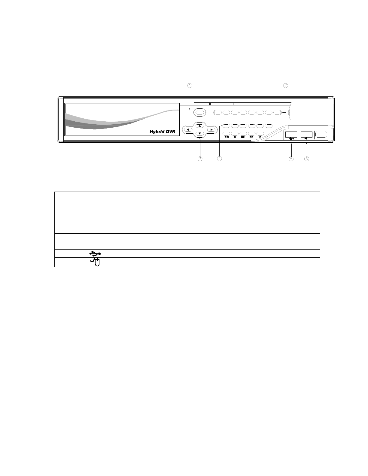
2 HARDWARE OVERVIEW
2.1 FRONT PANEL
REC
POWER REC PLAY HDD
MENU ENTER COPY
ZOOM
AUTO
PTZPTZ
AUTO
ZOOM
COPYENTERMENU
8/97654321
Hybrid DVR OPERATION
NO.
LABEL
OPERATION
PTZ 1 REC
Recording Button
2
1-9
Press for displaying Channel 1~9
3
▲▼◄►
Switch channel buttons
Up, Down,
Left, Right
4
CONTROL
PANEL
Menu, Enter, Copy, Zoom, Auto and PTZ Button.
5
4321
76 8
10 11 12
22
USB Connector
6
USB Mouse Connector

10
2.2 BACK PANEL
4
Audio In
1 2
3
DC 12V
Ethernet
HDMI
VGA OUT
COM
Relay
N.C N.O
GND
65 87
Alarm In
3 41 2
GND
D+D-
RS-485
eSATA
8765
Video In
4321
NO.
LABEL
OPERATION
1
AUDIO OUT
Audio Output
2
eSATA
eSATA connector
3
VIDEO OUT
(VGA)
Connect to LCD monitor
4
POWER
Connect to power adapter (DC 12V)
5
VIDEO OUT
(HDMI)
HDMI video output
6
ETHERNET
RJ-45 connector
7
RS-485/ ALARM
IN/ RELAY OUT
8 alarm in/ 1 relay out/ RS485
8
AUDIO IN
Audio input
9
VIDEO IN
BNC video input
10
FAN
Fan louvers

11
2.3 ALARM TRIGGER
There are four types of alarms: Motion detection, Video Loss Alarm, External Alarm, and
Digital Input from Camera. The following are the possible actions when the alarm is
triggered. Every action is configurable (Ex. the screen display pattern, the relay triggered
time.etc) and will be explained in the later chapter.
A. When Motion detection occurs:
a. The live screen pattern can be switch to single channel screen or split screen.
b. The external relay/ built-in buzzer can be triggered.
c. The alarm timepoint can be recorded in the event list, and you can search for the event
in playback.
d. On the channel which the alarm is triggered, the icon pops up to remind the user.
e. The pre/ post-alarm recording video can be sent to e-mail/ uploaded to FTP.
f. The CGI can be sent to an http server.
B. When External Alarm or Digital Input from Camera happen:
a. The external relay/ built-in buzzer can be triggered.
b. The alarm timepoint can be recorded in the event list, and you can search for the
event in playback.
c. On the channel which the alarm is triggered, the icon pops up to remind the user.
d. The pre/ post-alarm recording video can be sent to e-mail/ uploaded to FTP.
e. The CGI can be sent to an http server.
C. When Video Loss Alarm occurs:
a. The external relay/ built-in buzzer can be triggered.
b. Alarm timepoint can be recorded in the event list, and you can search for the event in
playback.
c. On the channel which the alarm is triggered, the icon pops up to remind the user.
d. The CGI can be sent to an http server.
12
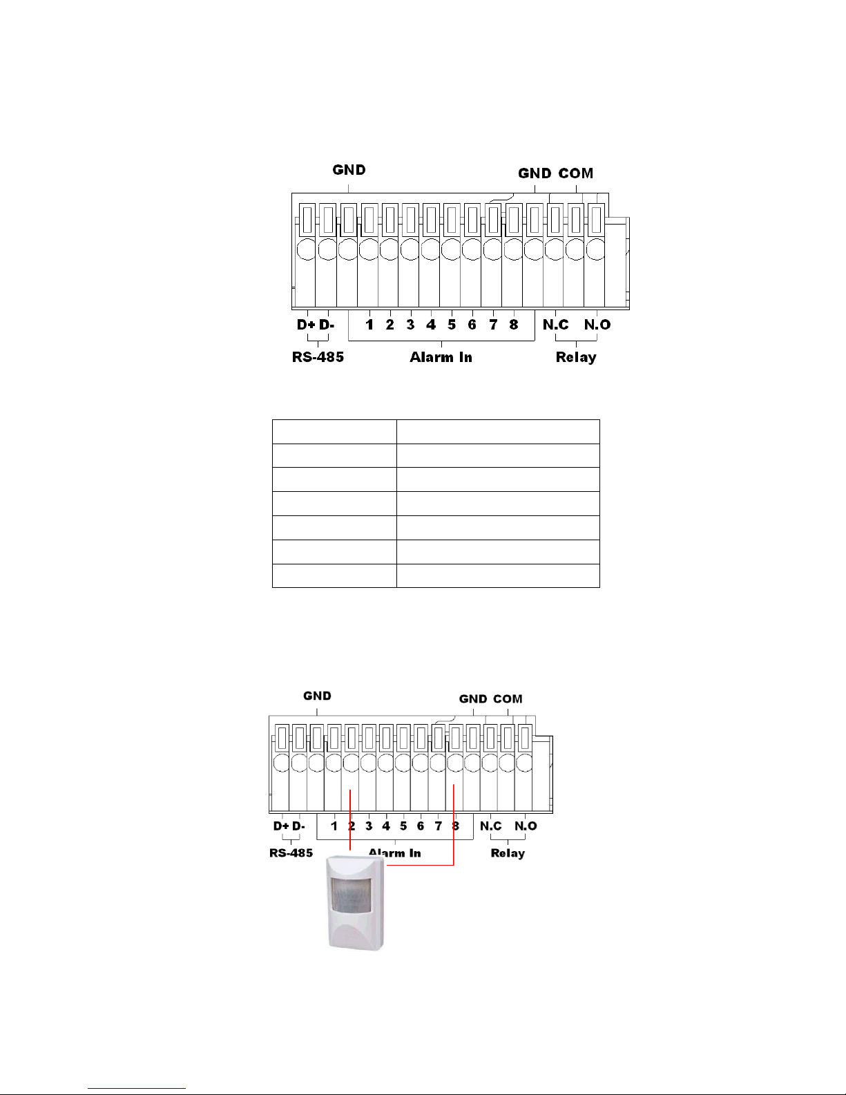
2.4 CONNECTION OF ALARM IN
EX1:Connect GND & Alarm to external IR detector.
RS-485 D+
RS-485 sends +/ receives +
RS-485 D -
RS-485 sends -/ receives -
GND
GND
ALARM IN 1-8
Camera alarm input.
N.C
Relay N.C.
N.O
Relay N.O.
COM
Relay COM
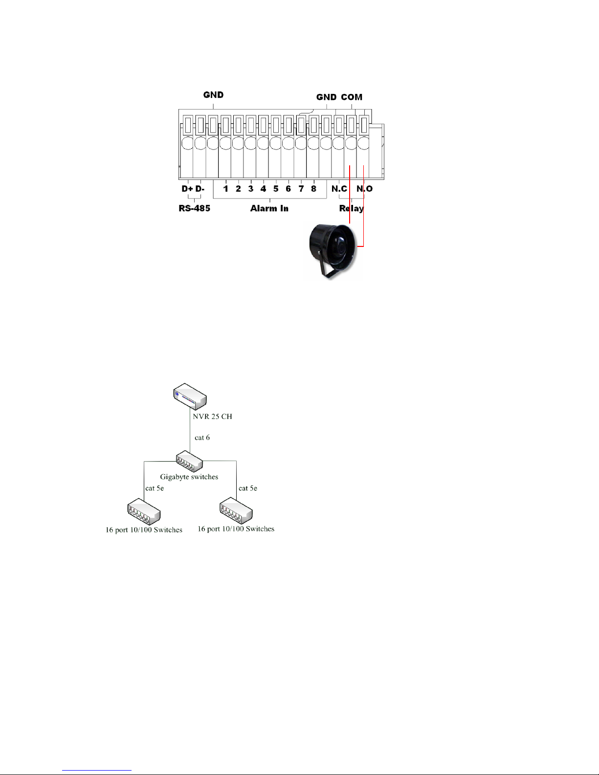
13
EX2:Connect N.O & COM to external siren.
Depending on the external device type, you may connect N.C & COM to external device.
2.5 NETWORK ENVIRONMENT RECOMMENDATION
When setting up 4Mbps per channel, it’s not
recommended to connect all 25 IP cameras under a
10/100 switch. It is suggested to connect 12~13 IP
cams on each 10/100 switch when you setting up
4Mbps per channel.
Make sure of using Cat.6 Ethernet cable when
connecting a Giga switch.
2.6 PTZ (PAN, TILT AND ZOOM) CAMERA
The following diagram shows the connection between the Hybrid DVR and a PTZ camera &
joystick controller. To control the PTZ camera via Hybrid DVR please check the CAMERA ID,
BANDRATE (default at 9600 bps) and the RS-485 cable.
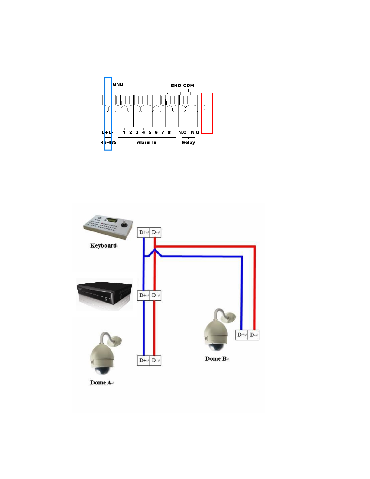
14
FOR 16 CHANNEL Model
Under “Two Core” connection, the controller can control the speed dome without any built-in
protocol into the Hybrid DVR. Moreover, one keyboard can be connected to a of MAX 256
units.
15
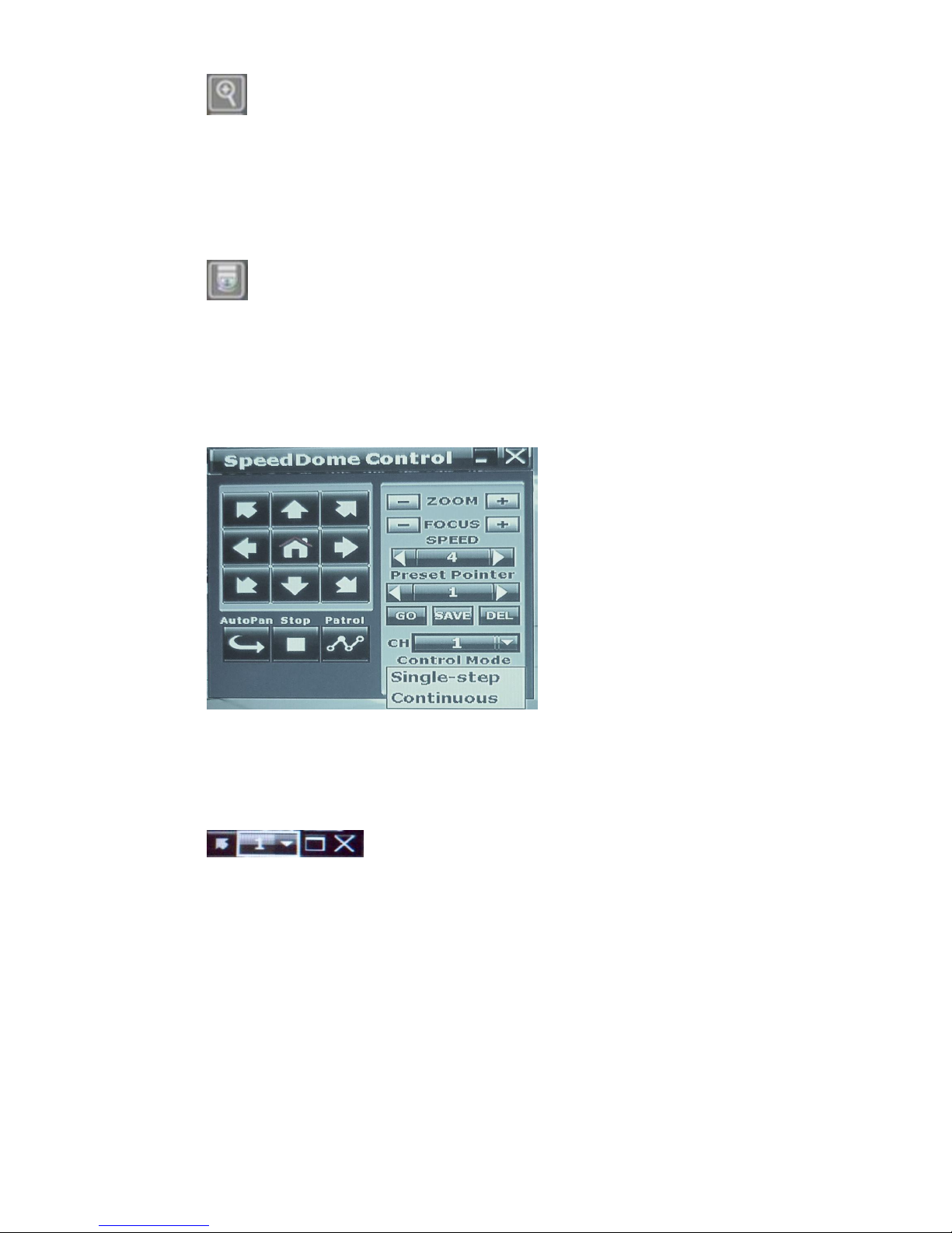
3 SYSTEM SETUP
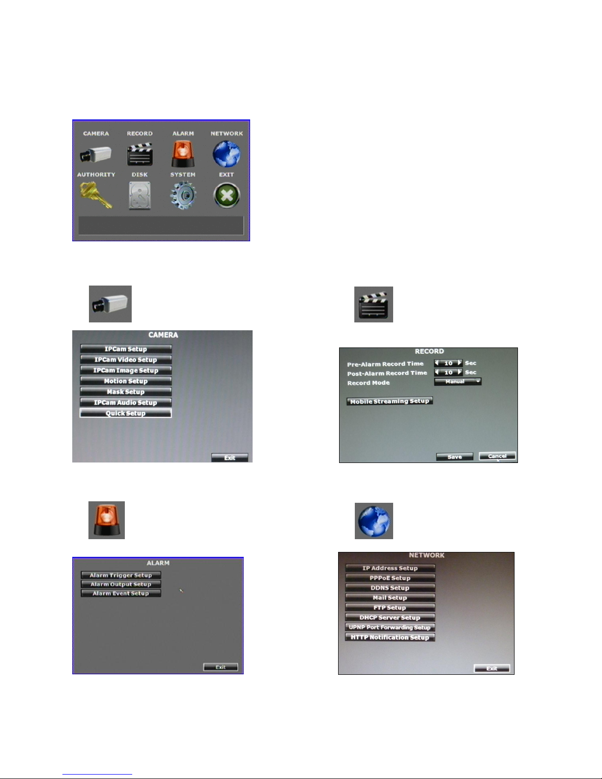
3.1 MENU SETUP INTERFACE(GUI)
A. CAMERA SETUP B. RECORD SETUP
C. ALARM SETUP D. NETWORK SETUP
16
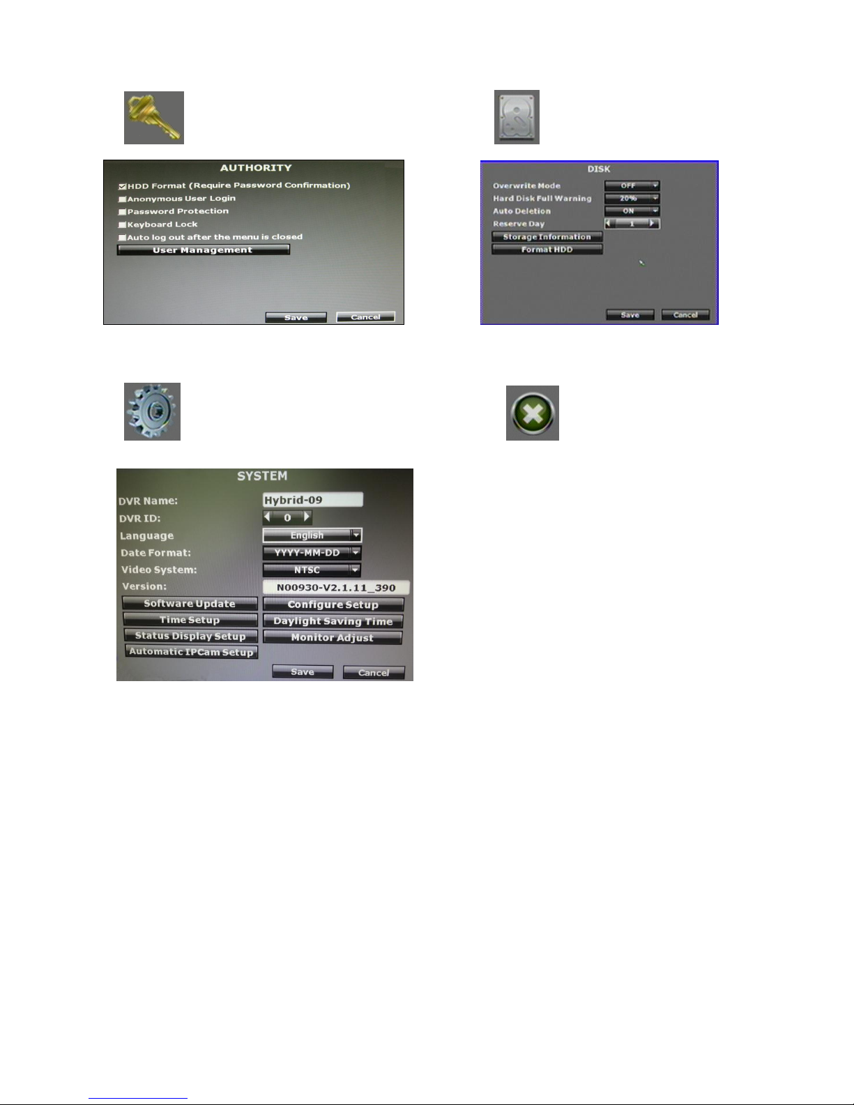
E. AUTHORITY SETUP F. DISK MANAGEMENT
G. SYSTEM SETUP H. EXIT
17
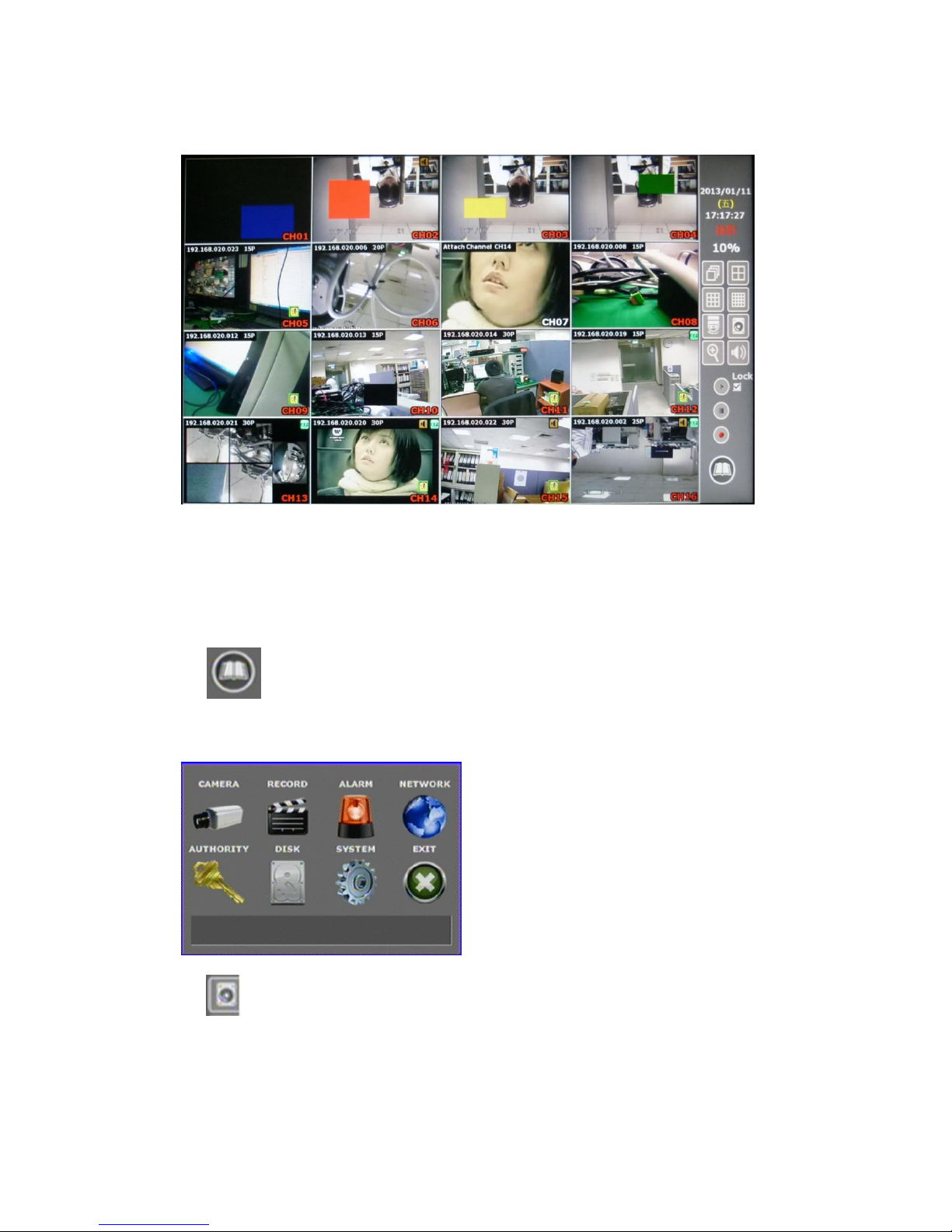
3.2 LIVE VIEWING AND POP-UP MENU (16CH model)
NOTE:*The pop-up menu can be activated by moving the mouse cursor to the bottom
of the live viewing screen.
A. GUI MENU BAR
On live viewing mode, press this button to get into the GUI menu.
B. DISK INFORMATION
On live viewing mode press this button to display disk information.
18
C. DIGITAL ZOOM
In the live full screen mode, left-click the button of the mouse to pull a range to zoom in
or zoom out the image. The user can right-click the button of the mouse to disable this
function. (NOTE: When using the mouse for operating digital zoom, the image can be
zoom-in to max. 16x.)
D. PTZ CONTROLLER
In the live-viewing mode, click this button to call the PTZ control panel.
NOTE:Only for PTZ cameras.
PTZ CONTROL
Press the minimization icon then the control panel becomes smaller:
Move the mouse and the arrow will follow the mouse and change direction. In this mode
user can click on the live view to control direction instead of the direction key on control
panel.
If a fisheye camera is connected:
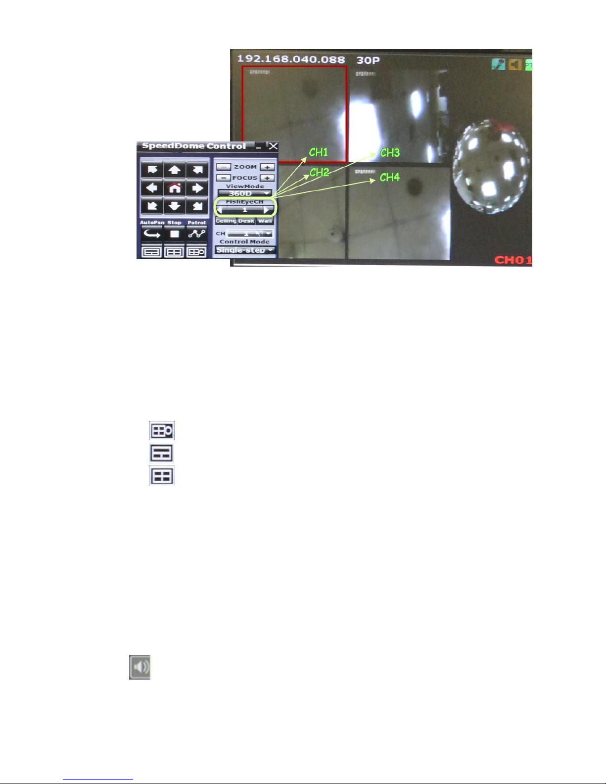
19
E-PTZ Steps:
(1) Select the channel number you want to setup, if there are several ones.
(2) Select the View Mode, 360 degree or 180 degree.
(3) Select the camera location, ceiling, desk, or wall.
(4) Select split screen pattern
: 360 degree panorama view + sub screens x4
: 180 degree flat view + sub screens x2
: sub screens x4
(5) After you decide the screen pattern, use the fisheye channel list to select one of the
sub screens. (as the green circle on the picture above). The selected one will be
indicated in a red frame.
(6) For the selected sub screen, use the 4-direction arrows and the “+” (zoom in) ”-”
(zoom out) icon for E-PTZ control.
(7) Control Mode: Select the E-PTZ moving mode, step by step or continuous.
(8) The AutoPan, Stop, and Patrol buttons are invalid here if the fisheye camera doesn’t
support those function.
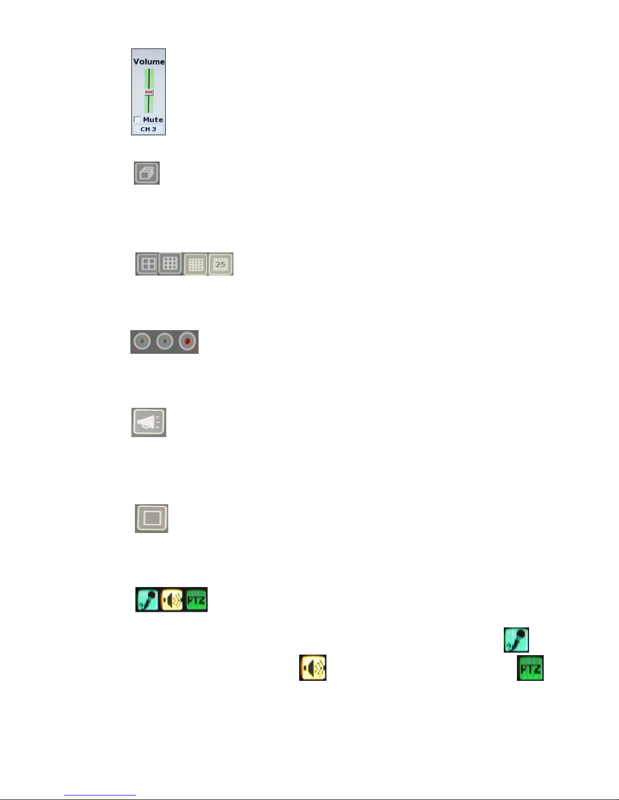
F. AUDIO VOLUME
Press this button, and the audio volume control board will pop up.
20
G. AUTO SWAP
Press it to start switch dwell. The interval depends on the setting in IP Cam Image Setup
when it’s on single channel view. For split screen the switch dwell interval is 5 sec.
H. DISPLAY CONTROL
Within live-viewing or playback mode, use display control to switch the camera channel.
I. RECORD AND PLAYBACK CONTROL
Same as front panel controller.
J. BROADCASTING
Press the bottom to enable or disable the one way audio. Broadcasting can be applied to
multiple channels simultaneously.
K. FULLSCREEN
Press the bottom for full-screen mode.
L. SOUND INPUT/ SOUND OUTPUT / PTZ CONTROL
There are little icon on the right top of the live vide of every channel. Click to
enable the two way audio. Click to enable the sound output. Click the
button to call out the control board. Note that if those functions are not supported by the
camera linked, you will not see the corresponding icons.
The sound options do not affect the audio recorded into the video. As long as the audio
21
setup is enabled, the playback video includes audio even if the sound output is turned
off.
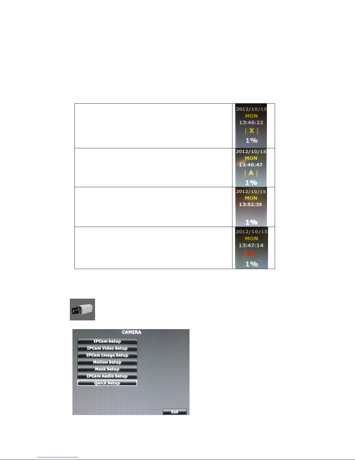
M. RECORDING STATUS
Beneath the date and time, it displays the current recording type:
Record mode: Schedule – NO REC period
Record mode: Schedule – ALARM REC period
Record mode: Alarm trigger
Record mode: Manual – Stop Recording
Record mode: Schedule – FULL REC period
Record mode: Manual – Recording
3.3 CAMERA SETUP

22
A. IP Cam Setup
A-1. IP Cam Quick Search
Press the “IP Cam Quick Search” button and click the “Search Device” button.
The Hybrid HYBRID DVR will search the IP CAM devices which IP address are
setup as the same domain as the Hybrid DVR IP address. Moreover, by clicking on
the IP Cam on the list will import the device information to the channel
automatically without any manual key-in step.
The IP Cam has to be under the same LAN with Hybrid DVR in order to be
successfully connected. Ex. If the Hybrid DVR IP address is 192.168.10.33, the IP
Cam IP address should be 192.168.10.X. You can edit the IP Cam IP address here
or on the IP Cam.
23
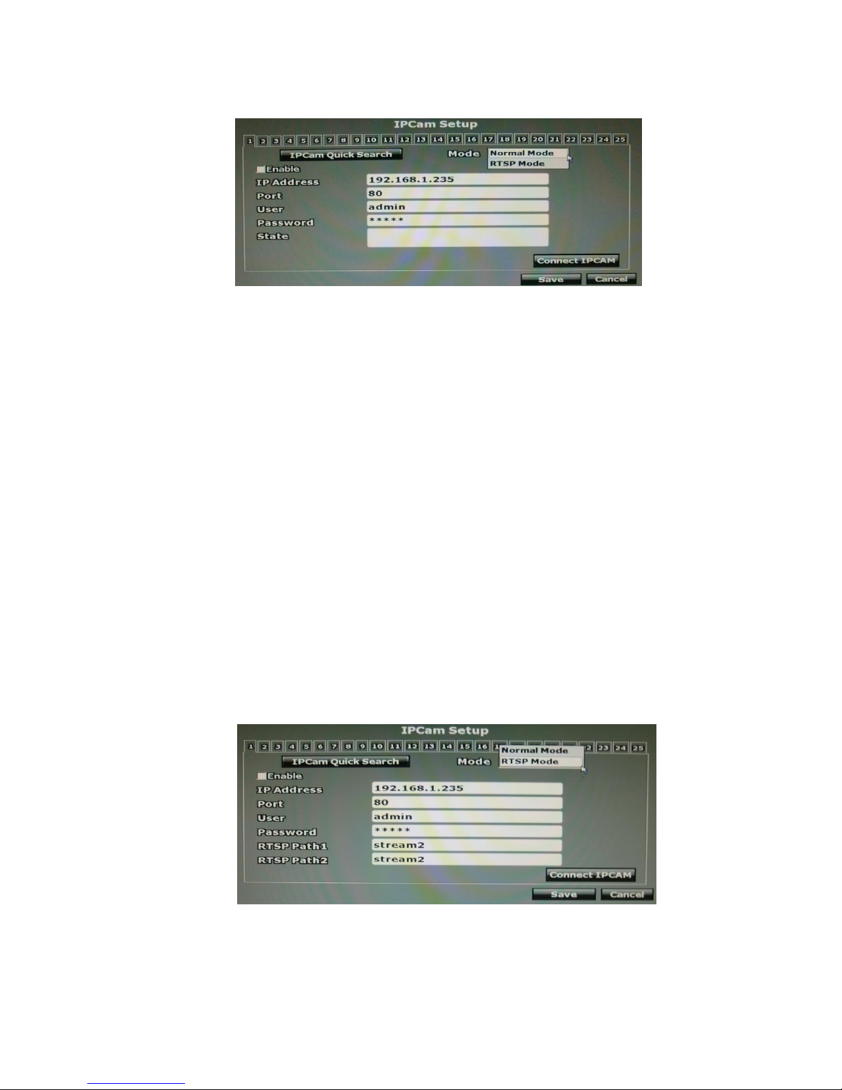
A-2. Normal Mode
1. Enable: Choose “Normal Mode”
2. IP Address:Insert the IP address of the connecting device.
3. Port:Insert the port number of the connecting device. Default port: 80
4. User:Insert the user name of the connecting device.
5. Password:Insert the password of the connecting device.
6. State:After clicking the “connect IP CAM” button to test the IP CAM device,
the connection state will reveal among this column.
Note: If the camera connected via ONVIF protocol, the PTZ control function
will not be supported.
A-3. RSTP Mode
Under RTSP Mode, the Hybrid DVR only support IP address indication, live video,
and video recording. Other functions like motion detection are not supported.
Key-in the IP address, port, username, and password of the device you are
connecting to the Hybrid DVR. You can find the information on the IP Cam.
To link to the IP camera, check the RTSP Path settings of your IP camera, and
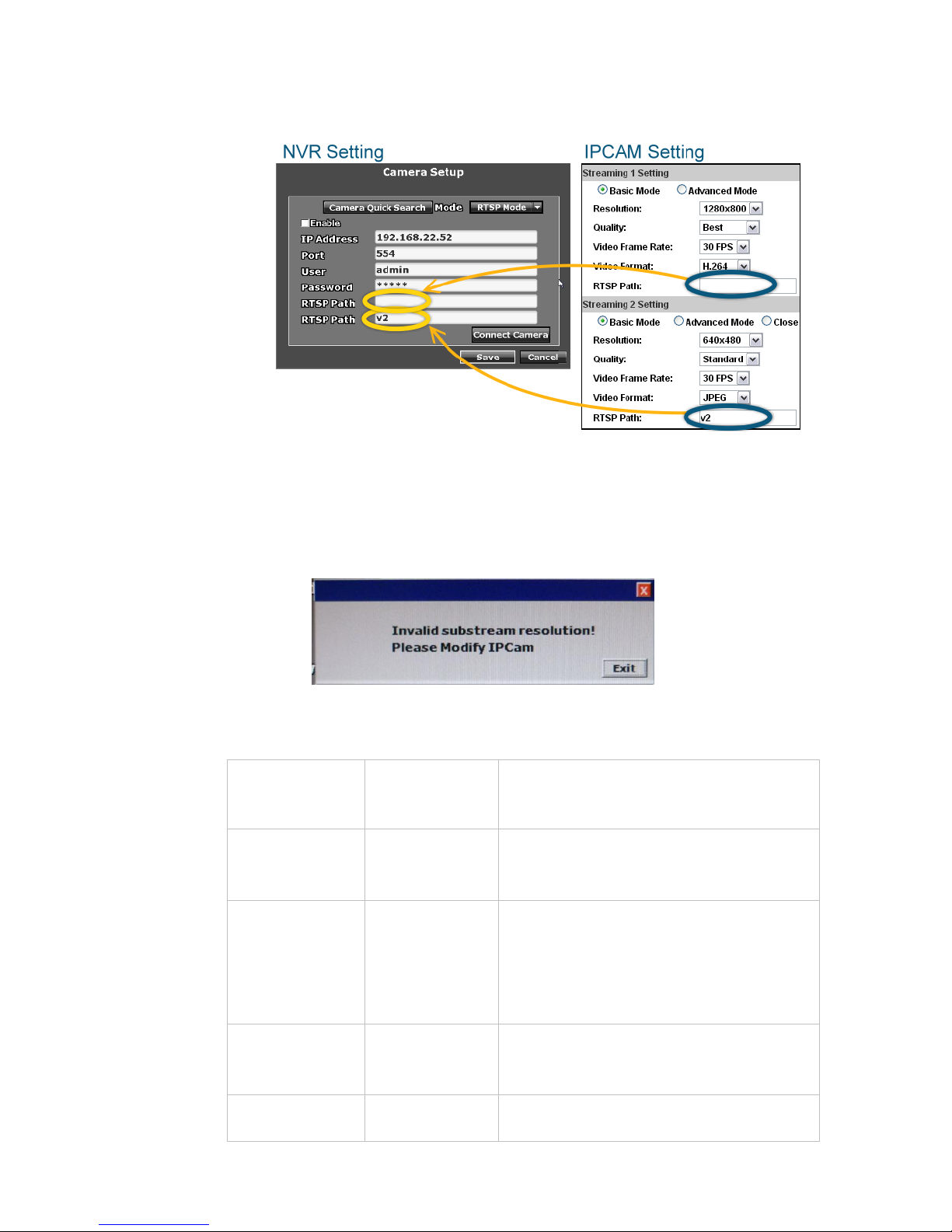
24
key-in the corresponding values of two streams in “RTSP Path 1” and “RTSP
Path 2”.
Note: When you select RTSP mode, make sure the substream resolution of
camera is VGA(640x480), otherwise you will receive the warning
message when you try to connect to the camera:
Examples of some RTSP settings:
RTSP Path 1
(IP Cam Main
stream)
RTSP Path 2
(IP Cam Sub
stream)
Result
1920 x 1080
640 x 480
OK.
Hybrid takes 1920x1080 streaming for
single channel view mode, and 640x480
streaming for split screen mode.
1920 x 1080
N/A
(Fill in nothing on
"RTSP Path 2")
Error Message: ”Invalid Substream
Resolution! Please modify IP Cam.”
Hybrid DVR takes 1920x1080 streaming for
both single channel view moe and split
screen mode. However, it can only allow
640x480 resolution for split screen, so it
shows a error in return.
640 x 480
N/A
(Fill in nothing on
"RTSP Path 2")
OK.
Hybrid DVR takes a 640x480 streaming for
both single channel view mode and split
screen mode.
N/A
(Fill in nothing on
640 x 480
OK.
Hybrid DVR takes a 640x480 streaming for
25
"RTSP Path 1")
both single channel view mode and split
screen mode.
640 X480
1920 x 1080
OK.
Hybrid DVR takes 1920x1080 streaming for
single channel view, and 640x480 streaming
for split screen.
1920 x 1080
1920 x 1080
Error Message: ”Invalid Substream
Resolution! Please modify IP Cam.”
Hybrid DVR takes 1920x1080 streaming for
both single channel view and split screen.
However, it can only allow 640x480
resolution for split screen, so it shows error
in return.
A-3. ROI
This function allows users to set up the channel as an attached channel. An
attached channel is based on a normal/ RTSP channel that has been set up, and can
display the same live view as the normal/ RTSP channel. The attached channel is
not physically linked to any camera, so it doesn't increase the bandwidth loading.
The users cannot setup motion detection or image adjustment on the attached
channel.
1. Enable: Choose “ROI”.
2. Attached Channel: Select a connected normal/ RTSP channel in the
drop-down menu.
3. Ratio: Use the arrows to adjust the zoom ratio, and press the red frame to
drag it to the area that you want it to show on the live view screen.
26
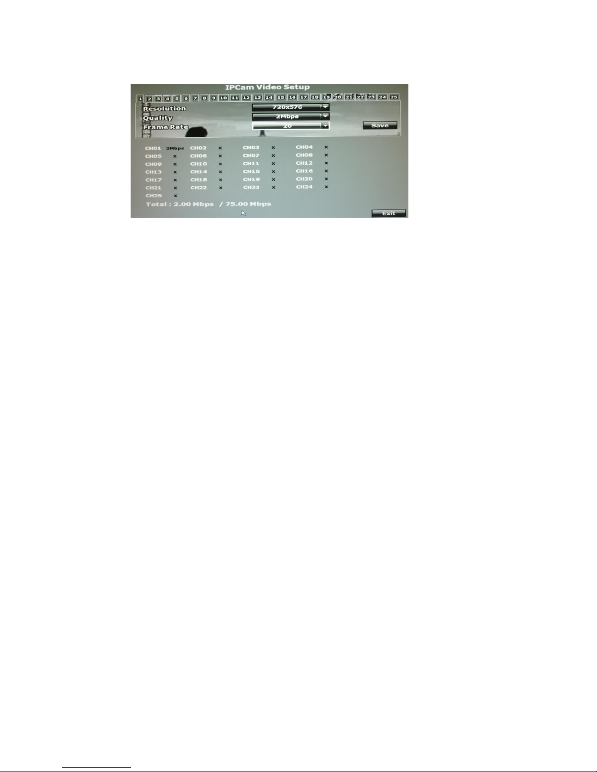
B. IP Cam Video Setup
B-1. Resolution
Click the drop down list to change the resolution of connecting device.
B-2. Quality
Click the drop down list to change the image quality.
For H.264 IP Cam above 1 Megapixel, the resolution options support “1M, 2M,
4M, 6M, 8M”.
For H.264 IP Cam less than 1 Megapixel, the resolution options support” 2Mbps,
1.5Mbps, 1Mbps, 512Kbps, 256Kbps”
For MPEG IP Cam, the resolution options support “Standard, Medium, Low”. (The
highest resolution option is “standard” due to the chip performance limits of IP
Cam)
B-3. FrameRate
Click drop down list to change the frame rate of connecting device.
27
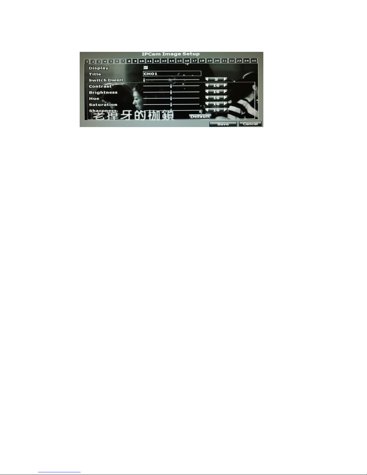
C. IP Cam Image Setup
C-1. Display
Use the mouse to enable or disable the camera display on the screen.
C-2. Title
Use the mouse to setup the title of the connecting IP device.
C-3. Contrast
Press ◄ or ► to change contrast level. The adjustment value is between 0~255
C-4. Brightness
Press ◄ or ► to change brightness level. The adjustment value is between 0~255
C-5. Hue
Press ◄ or ► to change hue level. The adjustment value is between 0~255
C-6. Saturation
Press ◄ or ► to change saturation level. The adjustment value is between 0~255
C-7. Sharpness
Press ◄ or ►/ mouse wheel to change sharpness level. The adjustment value is
between 0~15
C-8. Switch Dwell
Press ◄ or ► to change auto switch second. The value is between 0~99 sec.
28
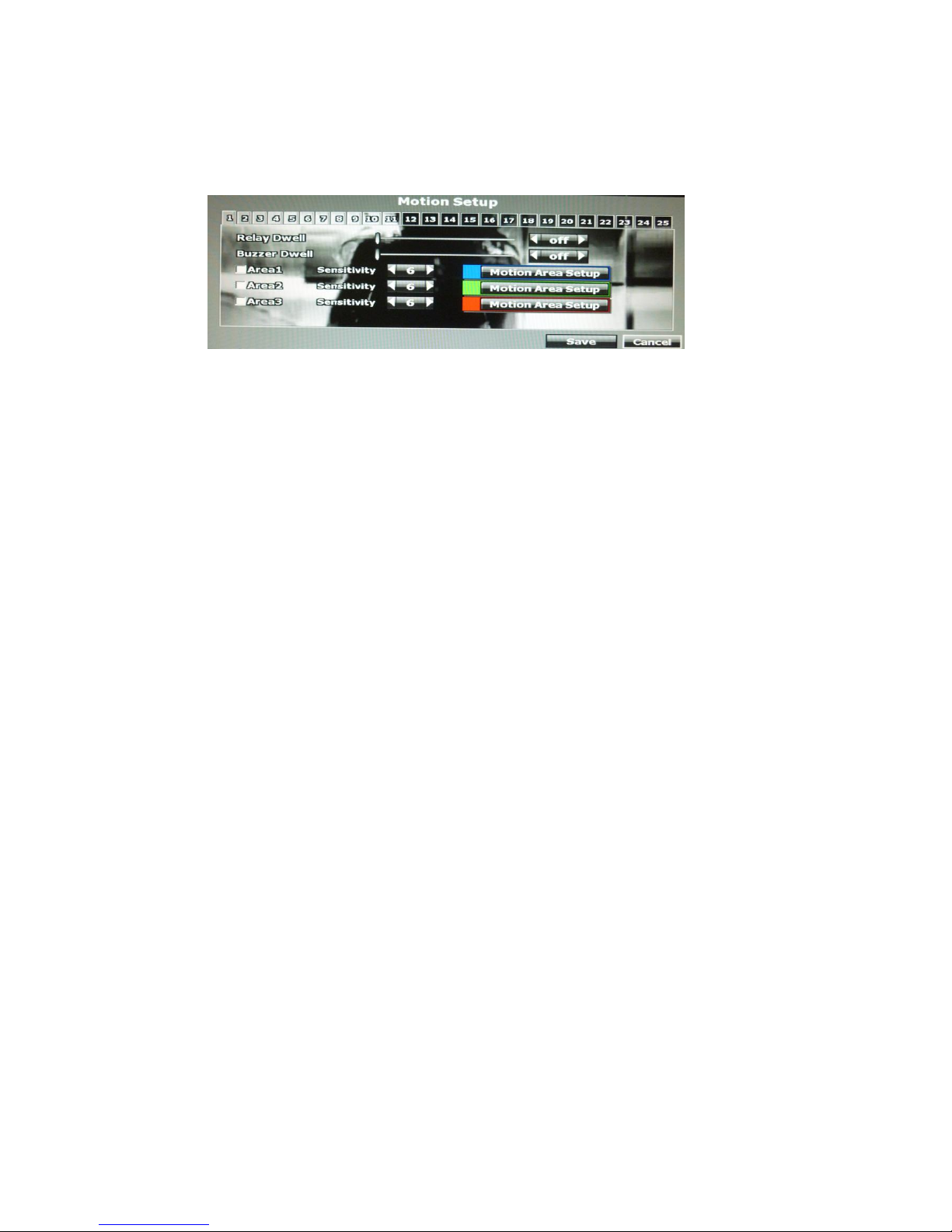
D. Motion Setup
D-1. Relay Dwell
Press ◄ or ► to change the relay time or disable the relay function.
D-2. Buzzer Dwell
Press ◄ or ► to change the buzzer time or disable the buzzer function.
D-3. Area1 Sensitivity
Press ◄ or ► to change the sensitivity of setup motion area in Area1. Click
“Motion Area Setup” and drag a blue area for motion detection.
D-4. Area2 Sensitivity
Press ◄ or ► to change the sensitivity of setup motion area in Area2. Click
“Motion Area Setup” and drag a green area for motion detection.
D-5. Area3 Sensitivity
Press ◄ or ► to change the sensitivity of setup motion area in Area3. Click
“Motion Area Setup” and drag a red area for motion detection
29
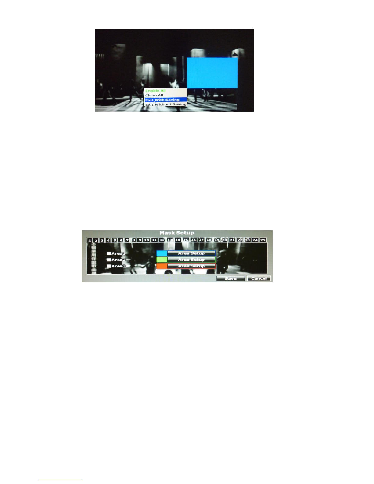
After dragging an area, right-click and select “Exit with saving” to complete the
area setup.
Select “Enable All” to set up global motion detection.
Select “Clean All” to clean the area of the current color in the view.
Select “Exit Without Saving” to go back to motion setup menu and not saving any
change.
E. Mask Setup
The masked area will not show both in the live view and playback recording.
E-1. Area1
Tick the “Area1” box and click “Area Setup” to drag a blue area for masking.
E-2. Area2
Tick the “Area1” box and click “Area Setup” to drag a green area for masking.
E-3. Area3
Tick the “Area1” box and click “Area Setup” to drag a red area for masking.
30
After dragging an area, right-click the mouse, select “Exit with saving” to complete
the area setup.
Select “Enable All” to set up global masking.
Select “Clean All” to clean the area of the current color in the view.
Select “Exit Without Saving” to go back to mask setup menu and the setting you
just changed will not be saved.
F. IP Cam Audio Setup
The channel ticked means the sound from camera will be recorded into the playback
video. On the contrary, no sound will be recorded in the playback video of the channel
which is not ticked.
G. Quick Setup
Other than “IP CAM Setup”, you can choose another way to complete the IP camera
connection job: using Quick Setup.
31
G-1 Key-in information manually
All the channel list are displayed. You can key-in the IP address, port, and user
name & password of the IP camera, and then assign the channel number. Tick
“Enable” to connect to the IP camera.
G-2 IP CAM Quick Search
With Quick Search, you do not need to type the IP address. Click “IP CAM
Quick Search” to enter the search menu.
The machine searches for all the IP devices listed under the LAN. Find the IP
camera you want to connect to, assign a channel number for it, and tick “Enable”
so for enabling this IP camera and adding it to the all-channel list.
Back to the all-channel list, you can key-in the user name and password, and tick
“Enable” to connect to the camera.
If you want to revise the IP setting of a camera, click “Edit”:
 Loading...