

Page 1

HVR User’s Guide
HVR-04
(v 3.1)
Page 2

FCC Compliance Statement
Caution : Any changes or modifications in construction of this device which are not expressly approved
the party responsible for compliance could void the user's authority to operate the equipment.
NOTE : This equipment has been tested and found to comply with the limits for a Class B digital device,
pursuant to part 15 of the FCC Rules. These limits are designed to provide reasonable protection against
harmful interference in a residential installation. This equipment generates, uses and can radiate radio
frequency energy and, if not installed and used in accordance with the instructions, may cause harmful
interference to radio communications, However, there is no guarantee that interference will not occur in a
particular installation. If this equipment does cause harmful interference to radio or television reception,
which can be determined by turning the equipment off and on, the user is encouraged to try to correct the
interference by one or more of the following measures:
- Reorient or relocate the receiving antenna.
- Increase the separation between the equipment and receiver.
- Connect the equipment into an outlet on a circuit different from that to which the receiver is
connected.
- Consult the dealer or an experienced radio/TV technician for help.
Warning
1. Danger of explosion if battery is incorrectly replaced. Replace only with the same or equivalent type.
2. Disposal of used batteries according to the general recommendations against the environmental
pollution.
3. Do not throw the batteries into a fire, and do not heat, short-circuit or attempt to disassemble the
batteries.
4. the battery in remote controller should not be recharged.
Page 3

Important Notice
1. Do not place heavy objects on the top of the HVR-04.
2. HVR-04 is for indoor use. It is not weatherproof. Use HVR-04 with referring to its environmental
specifications (Temperature & Humidity). To clean the HVR-04, gently wipe the outside with a clean dry
cloth.
3. Be sure to use a DC adapter that is provided by Web Gate Inc. Connecting HVR-04 directly to an AC
current will cause electric damages to HVR-04.
4. Be careful not to drop the HVR-04. Physical shocks may harm the product. In addition, be sure the
HVR-04 is secured after installation.
5. HVR-04 is made of metal. Therefore you can hurt human beings if you throw it to them or hit on them.
When installing HVR-04, be cautious to locate on safe places where children are unreachable.
6. If HVR-04 does not operate properly, please contact the closest HUNT ELECTRONIC distributor for
after sales service. Tampering or disassembling the product will void the warranty.
7. Security surveillance laws may differ for each country. Therefore, please contact the local region first
to avoid any surveillance law violations.
Page 4

Contents
OVERIVEW...................................................................................................................................7
1. Introduction ..........................................................................................................................7
2. Product description ............................................................................................................. 9
2.1. Front panel......................................................................................................................9
2.2. Rear panel.....................................................................................................................10
2.3. Installation summary..................................................................................................... 11
Basic configuration...................................................................................................................12
3. Monitoring........................................................................................................................... 12
3.1. Viewing basic screen....................................................................................................12
3.2. Viewing single full screen..............................................................................................12
3.3. Viewing multi screen.....................................................................................................12
3.4. Viewing all channels with sequence mode................................................................... 13
3.5. Viewing an alarm triggered channel............................................................................. 14
3.6. Viewing images with digital zoom................................................................................. 14
3.7. Viewing with connected PTZ.........................................................................................14
3.8. Using relay.................................................................................................................... 16
3.9. Using screen lock..........................................................................................................16
4. Playback.............................................................................................................................. 16
4.1. Playback via various mode........................................................................................... 16
4.1.1. Playback via basic screen (full screen).................................................................16
4.1.2. Playback via multi screen...................................................................................... 17
4.1.3. Playback with digital zoom.....................................................................................17
4.1.4. Various playback modes........................................................................................17
4.2. Using search mode....................................................................................................... 18
4.3. Copy / Backup / Delete data manager.......................................................................... 19
4.3.1. Copy image............................................................................................................19
4.3.2. Backup manager....................................................................................................20
4.3.3. Delete data ............................................................................................................ 21
4
Page 5

5. Configuration...................................................................................................................... 22
5.1. Quick setup................................................................................................................... 22
5.1.1. Date/Time..............................................................................................................22
5.1.2. Recording..............................................................................................................25
5.2. Camera – analog camera channels (Ch 1 ~ Ch 4).......................................................27
5.3. Recording – analog camera channels (Ch 1 ~ Ch 4).................................................30
5.3.1. Global setting......................................................................................................... 30
5.3.2. Each channel setting.............................................................................................31
5.4. Setting alarm recording.................................................................................................35
5.4.1. Setting sensor........................................................................................................35
5.4.2. Setting motion detection........................................................................................ 36
5.4.3. Setting text............................................................................................................. 39
5.4.4. Setting global alarm recording...............................................................................41
5.4.5. Setting each channel............................................................................................. 42
5.5. Alarm action.................................................................................................................. 43
5.5.1. Schedule................................................................................................................ 43
5.5.2. Setup ..................................................................................................................... 44
5.6. Monitor..........................................................................................................................45
5.7. System..........................................................................................................................47
5.7.1. Audio......................................................................................................................47
5.7.2. Time schedule........................................................................................................48
5.7.3. Special time ........................................................................................................... 49
5.7.4. Security..................................................................................................................50
5.7.5. Disk setup.............................................................................................................. 51
5.7.6. Network..................................................................................................................52
5.7.7. Serial setup............................................................................................................ 58
5.7.8. Miscellaneous........................................................................................................59
5.8. Utility ............................................................................................................................. 61
5.8.1. Disk manager.........................................................................................................62
5.8.2. USB utility..............................................................................................................64
Advanced configuration...........................................................................................................66
6. Using IP cam....................................................................................................................... 66
6.1. Activating IP cam menu................................................................................................66
5
Page 6

6.2. Camera setting – IP camera channels (Ch 5 ~ Ch 16).................................................67
6.2.1. Configuration.........................................................................................................67
6.2.2. Local IP cam list.....................................................................................................69
6.3. Recording – IP camera channels (Ch 5 ~ Ch 16).........................................................70
6.4. Alarm rec. - IP cam channel (Ch 5 ~ Ch 16).................................................................71
6.5. IPCam sensor...............................................................................................................72
6.6. IPCam Relay.................................................................................................................72
7. Connecting external device ..............................................................................................73
7.1. Using text device...........................................................................................................73
7.1.1. Setting at text menu............................................................................................... 73
7.1.2. Setting at serial setup’s RS232 men u...................................................................74
7.1.3. Setting at alarm rec. menu .................................................................................... 75
7.1.4. Setting at recording menu ..................................................................................... 76
7.2. Using keyboard............................................................................................................. 77
7.2.1. Setting at serial setup’s RS232 men u...................................................................77
7.2.2. Setting at serial setup’s PTZ menu........................................................................77
APPENDIX .................................................................................................................................78
Appendix #1 Technical specification....................................................................................... 79
Appendix #2 Utilizing IP addresses on local network...........................................................82
#2.1 Introduction...................................................................................................................... 82
#2.2 IP construction and network class................................................................................... 82
#2.3 C-class network...............................................................................................................83
6
Page 7

OVERIVEW
1. Introduction
What is HVR-04?
HVR-04 supports 4 analog video channels and 12 IP video channels simultaneously. Video, Audio, and
Text Event-Logs are digitized and stored on two internal hard-drives. Using a ‘Proprietary Wavelet
Algorithm,’ average file size is 1-5KB while still maintaining clarity high enough for facial-recognition.
In addition, Wavelet-compressed images are impossible to manipulate.
Due to our proprietary Wavelet Algorithm, the HVR-04 processes analog video into crisp, clear, and
court-admissible pictures that are up to 500% smaller than comparable JPEG images. With this efficiency,
HVR-04 records over 30 days on a 200GB hard disk drive when recording 4 channels at the speed of
10ips per channel. HVR-04 also allows users to record and playback audio for one channel.
Setting-up HVR-04 is as easy as setting up a VCR. HVR-04 starts to record as soon as power is supplied
and CCTV cameras are connected. HVR-04 offers an easy setup, as well as advanced menus. With ‘Quick
Setup’, HVR-04 can be setup and begin recording in as little as 5 minutes. The default settings offer
quality and efficiency without the hassle of confusing menus.
Equipped with (3) IEEE 1394 ports (Fire-Wire) and (3) USB ports, HVR-04 can expand its recording
capacity to up to 4TB easily. For easy backup, Windows (FAT32) formatted HDD is compatible with
HVR-04. Simply back up the desired data and connect the HDD to your PC to review critical images.
7
Page 8

Key features
- Expandable up to 16 channels (4 analog video channels + 12 IP video channels)
- 1 channel audio recording & playback
- Recording, Playback, Back-up, Network recording, and Network playback at the same time
(Pentaplex)
- Total 120 ips recording speed (Analogue video 60ips + IP video 60ips)
- Total 120 ips display speed (Max 60ips over Network)
- Displaying live and recorded images on PC as well as CCTV Monitor
- Built-in hardware Quad Splitter for analog video
- Built-in software multiplexer for all 16 live monitoring channels
- (1 / 4 / 9 / 13 / 16Ch Mode on CCTV Monitor as well as PC)
- Maximum 4TB storage capacity (IEEE 1394 for external HDD)
- Various configuration with recording and playback conditions
- Intelligent file system for managing event triggered video data
- ATM/POS transaction information text recording and search with corresponding video
(Text search function is supported through HVR-04 Manager program)
- 4 pairs of sensor inputs and alarm outputs
- Built-in hardware motion detection with search function (64-division comparison)
- Back-up with IEEE 1394(FiWi).
- PTZ Control (Preset support) via RS 232 and RS 485/RS422
- User-friendly 32bit True-colored Graphic OSD Menu
- Dynamic IP (DHCP, Floating IP) support (when xDSL and Cable Modem are used)
- Wavelet compression: 1-5KB (Average file size with standard image quality)
- Embedded Linux OS for excellent stability and reliability
- IR remote controller (User controls PTZ with remote controller)
- HVR-04 Manager (User Interface of PC) is to be listed with 16 units of HVR-04 on a program
(256 chnnels (16 sets of HVR-04 x 16channel) are controllable through a program)
8
Page 9
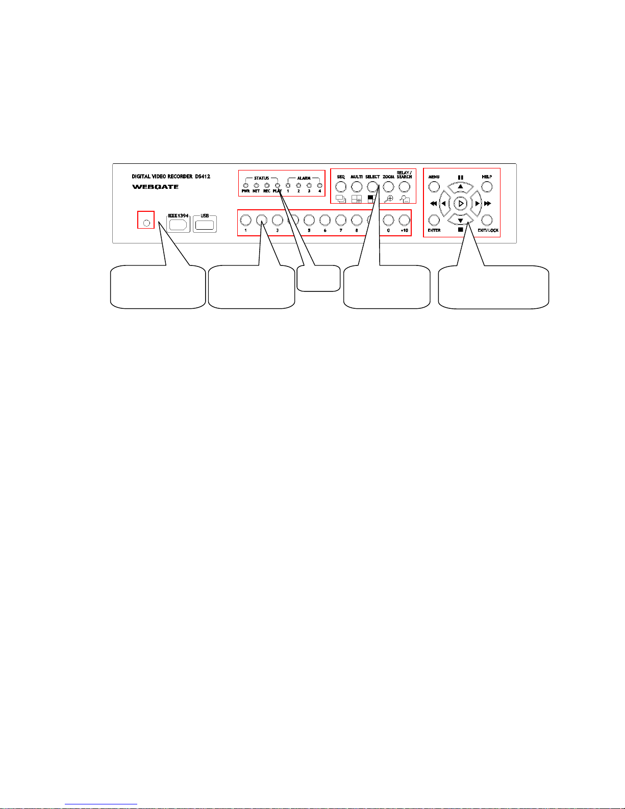
2. Product description
2.1. Front panel
(1) Remote Controller Receiver
(5) Direction/Replay
Button
(2) Channel
Selection Button
(4) Function
selection button
(3) LED
(1) Remote
Controller Receiver
(2) Channel Selection Button
To select video input channel in monitoring and playback mode
(3) LED
PWR
: Displays power status. When lit, power is supplied.
NET
: Displays the status of Ethernet connection and rate of communication. When blinking,
data being transmitted or received over the Ethernet.
REC
: Displays image recording status. The rate of blinking indicates the speed of recording.
(i.e. When blinking rapidly, HVR-04 is recording at a high rate; when blinking slower, the
HVR-04 is recording at a lower rate.)
PLAY
: Displays playback status. The rate of blinking indicates the speed of playback. (i.e. When
blinking rapidly, HVR-04 is playing back at a high rate; when blinking slower, the HVR-
04 is playing back at a lower rate.)
(4) Function selection button
SEQ
: To select Sequencing Mode. HVR-04 will automatically display all connected
channels in successive order.
MULTI
: To select the multi-channel display (4/9/16/13 divided screen).
SELECT
: To select video channel for PTZ control in monitoring mode and for
Copy/Backup/Delete in Playback mode
ZOOM
: To activate the digital zoom (single channel mode only).
SEARCH/RELAY
: To search the recorded image in Playback mode or to toggle the Relay On/Off
function in Monitoring mode
9
Page 10
(5) Direction/Replaying Button
MENU
: To set PTZ or access Configuration menu.
ENTER
: To enter and confirm the selected menu.
HELP
: To display the image information (Date, Transfer speed, etc).
EXIT/LOCK
: To exit from the selected menu or lock a screen.
Arrow key
: To Replay function in playback mode or to move a direction in other modes.
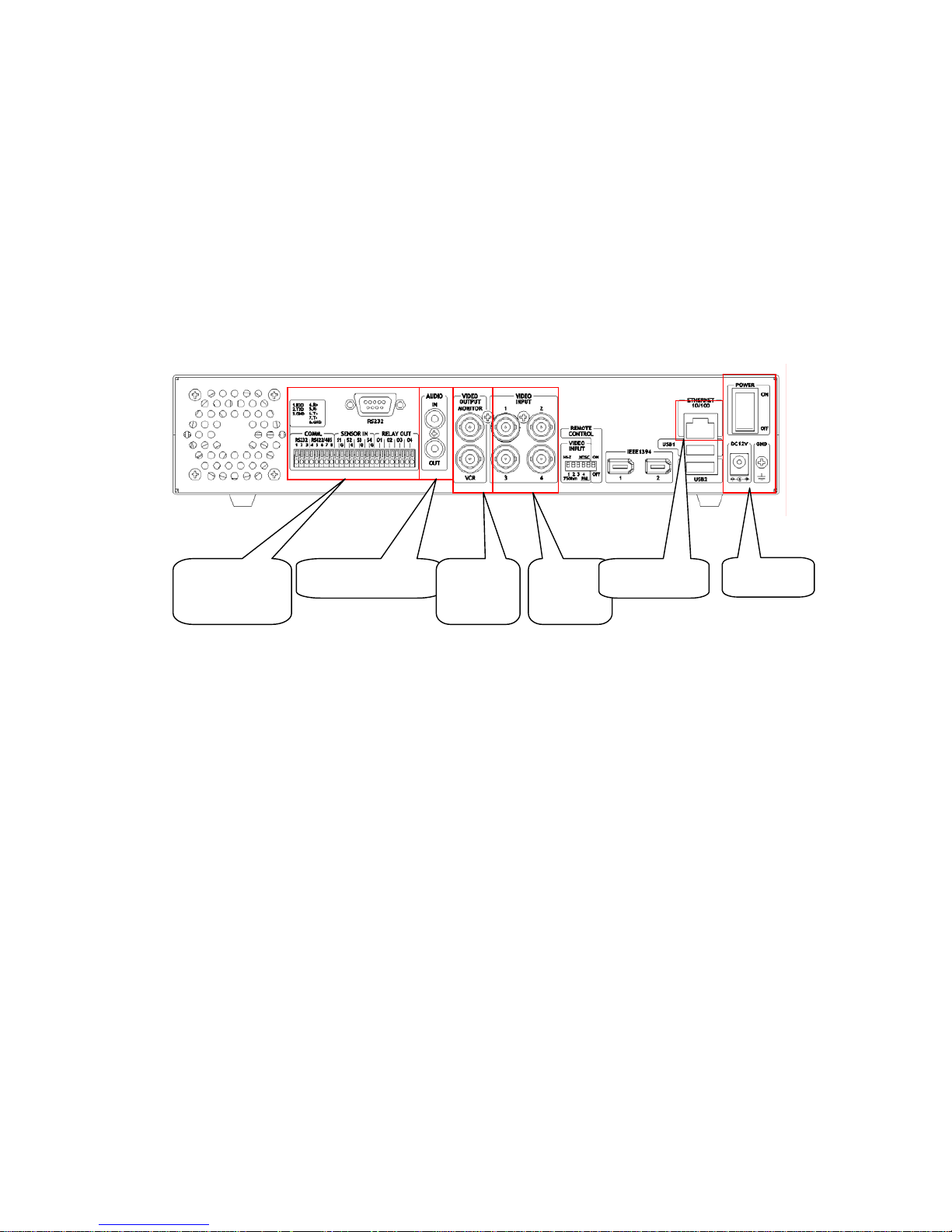
2.2. Rear panel
(4) Video
Input
(5) Ethernet
(6) Power
(3) Video
Output
(2) Audio port
(1) Serial Port
& DIO
(1) Serial Port & DIO
Serial
: RS232 9Pin D-Sub Connector & RS232/422/485 terminal block
Sensor In
: 4 sensor inputs
Relay Out
: 4 alarm relay outputs
(2) Audio port
- 1 audio input & 1 output
(3) Video Output
- 1 monitor output & 1 VCR output
(4) Video Input
- 4 video inputs
(5) Ethernet
(6) Power
10
Page 11

2.3. Installation summary
- Connect Camera
- Connect Monitor
- Connect Ethernet.
(This is optional to view image on remote location or to add IP channel to HVR-04)
- Connect Audio
- Connect Power & Run
11
Page 12
Basic configuration
3. Monitoring
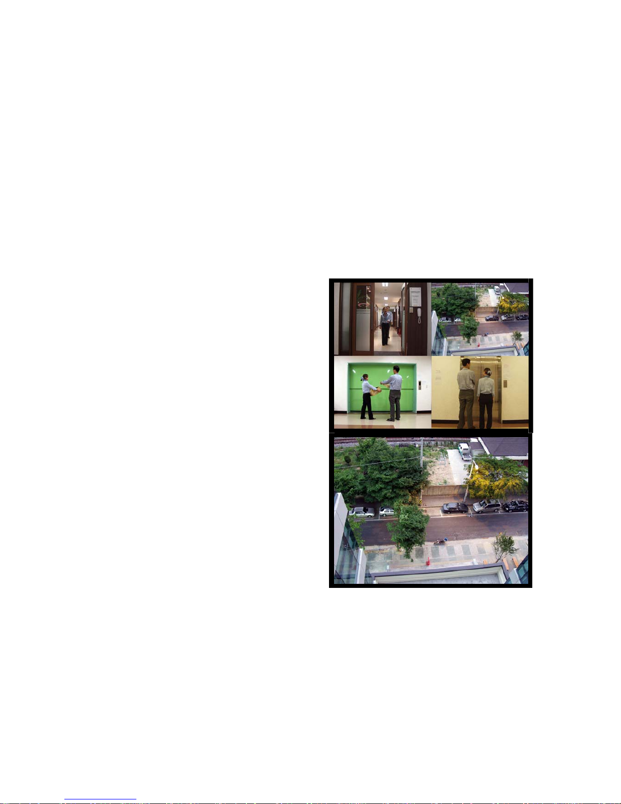
Once power is supplied to HVR-04, default quad-multi monitoring mode (analog channels 1~4) will be
displayed. The following steps apply for all HVR-04’s monitoring menus.
<Button control>
- Press [MULTI] button on the front panel of HVR-04 to change the multi screen mode (4, 9, 16, 13).
- For sequence mode, press the [SEQ] button on the front panel of HVR-04. To configure the
sequential cycle, access the “Monitor” tab of Configuration Menu.
3.1. Viewing basic screen
- Insert AC cord’s plug in a wall outlet and turn
the power switch “On.”
- LED is on and HVR-04 starts booting.
- After start-up, the basic screen (quad-multi) is
displayed.
* If user password is set, a dialogue box for entering the
password will appear.
3.2. Viewing single full screen
- Press the desired channel number button on the
front panel of HVR-04.
- When selecting channels between channel 10
and 16, press the [+10] button first, then the
second number.
- To return to the multi-view screen, press the
[MULTI] button.
3.3. Viewing multi screen
- Press the [MULTI] button to view several channels simultaneously.
- To change the multi screen configuration, press the [MULTI] button. 4, 9, 16, or 13 multi screens
will be displayed.
- In quad-multi mode, images of channels 1 to 4 are displayed. Channels 1 to 9 are displayed in 9-
multi mode, channels 1 to 16 in 16-multi mode, and channels 1 to 13 in 13-multi mode.
12
Page 13
3.4. Viewing all channels with sequence mode
- All channels can be viewed in successive order automatically using the [SEQ] button.
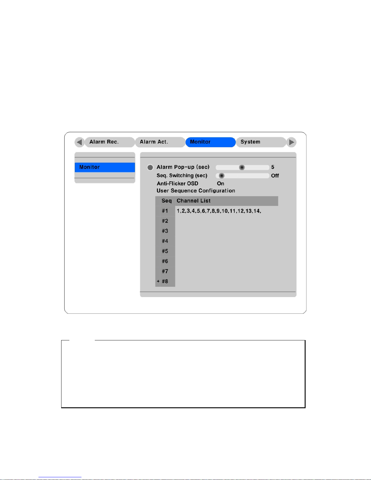
- Press the [MENU] button on the front panel to set-up the sequential cycle.
- Select “Monitor” tab of Configuration menu.
- Move to “Configuration” below “Monitor” using the down arrow button on HVR-04 front panel.
- Press the [ENTER] button to enter the menu.
- Select “Seq. Switching (sec)” and press the [ENTER] button.
- Set any value between 1 and 60 seconds.
- Then press the [SEQ] button from any viewer mode (except 16/13-multi screen).
<Note>
Sequence mode can run only when connected and activated cameras are more than multi screen.
With single full screen mode, activated cameras should be two or more. With quad-multi screen mode,
there should be five or more activated cameras. With 9-multi screen mode, there should be ten or more
activated cameras. (SEQUENCE MODE ONLY SUPPORTS 4- AND 9- MULTI SCREENS). Channel
order cannot be changed. For example, with quad-multi screen, Ch. 1/2/3/4 are displayed and then
Ch.5/6/7/8 are displayed.
- To end sequence function, press the [SEQ] button.
13
Page 14
3.5. Viewing an alarm triggered channel
- When an alarm is triggered, the related channel will pop-up full screen automatically.
- Set ‘Alarm Pop-up Screen’ function to “On” in “Configuration” under the “Monitor” tab, and set
the display duration in “Pop-up Hold (sec)”
- If more than one channel is triggered by an alarm, the related channels will be displayed
simultaneously in a multi-screen. In order to move current screen, press any button.
3.6. Viewing images with digital zoom
- In Single Full Screen mode, live and recorded images can be expanded using the Digital Zoom
feature.
- To enable the digital zoom, press the [ZOOM] button.
- Digital Zoom will expand the image to twice its normal size.
- Default location of the digital zoom is in the center of screen. The zoom box can be moved each
10
th
step to left and right and 4th step up and down.
- To move the zoom box, use the [Arrow] button.
- To cancel the zoom box, press the [ZOOM] button once more.
3.7. Viewing with connected PTZ
- Pan/Tilt/Zoom (PTZ) devices can be controlled through the HVR-04
when a PTZ device is connected and properly configured under “Serial
Setup.
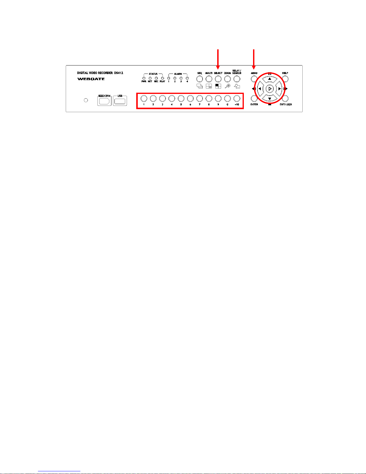
- While in Monitor mode, press the [SELECT] button.
- Channel selection icon will be displayed.
- Move the icon to the channel to control with the [Arrow] button.
- Press the [MENU] button.
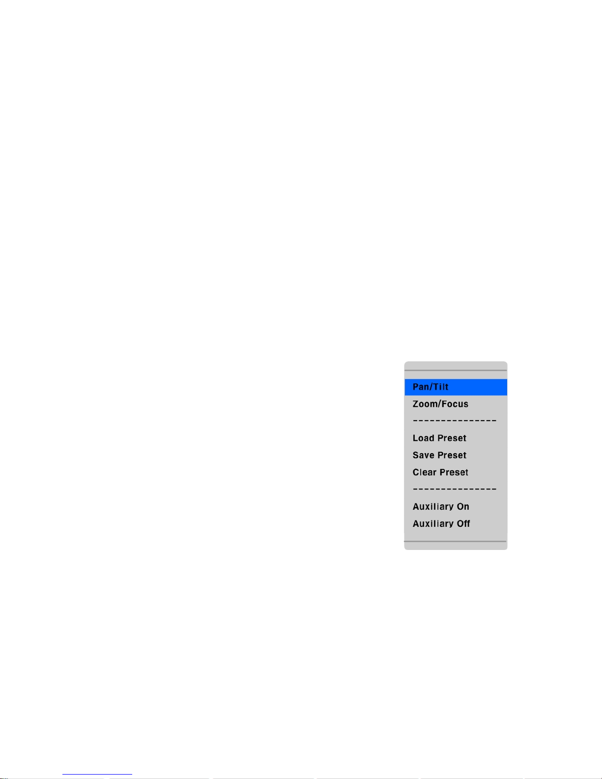
- PTZ menu (Pan/Tilt, Zoom/Focus, Load Preset, Save Preset) will
appear.
- Press the [ENTER] button after selecting the desired function.
14
Page 15
Pan/Tilt Control
To control Pan and Tilt during live image monitoring mode.
-
Press the [SELECT] button. Move the “Select” icon to the desired channel.
- Press the [MENU] button.
- Select ‘Pan/Tilt’ from the PTZ Menu.
- Control pan and tilt function using the up, down, left and right arrows.
Zoom/Focus Control
To control Zoom and Focus during live image monitoring mode.
- Press the [SELECT] button. Move the “Select” icon to the desired channel.
- Press the [MENU] button.
- Select ‘Zoom/Focus’ from the PTZ Menu.
- Control zoom and focus functions using the up, down, left and right arrows of front panel.
Load Preset
To load preset for dome camera during live monitoring mode.
- Press the [SELECT] button. Move the “Select” icon to the desired channel.
- Press the [MENU] button.
- Select ‘Load Preset’ from the PTZ Menu.
- Press number button for desired preset on the front panel.
Save Preset
To set a new preset point for dome camera during live monitoring mode
- Move dome camera to the desired position using the ‘Pan/Tilt’ and ‘Zoom/Focus’ menus.
- Press the [SELECT] button.
- Press the [MENU] button.
- Select ‘Save Preset’ from the PTZ Menu.
- Designate a number for the preset position by pressing a number button on the front panel.
15
Page 16

3.8. Using relay
- To set relay on/off. (HVR-04 supports four relay outputs.)
- Press the [SEARCH/RELAY] button.
- The icon of “Relay On” shows.
- Press the relay number button between 1 and 4, and then the related relay out signal will be
transmitted.
- In order to set relay off, press the [SEARCH/RELAY] button again.
- Then “Relay On” shows because relay keeps being set as on.
- Press the [SEARCH/RELAY] button again, and then the icon of “Relay Off” will show.
- Press the relay a number button to set off.
3.9. Using screen lock
- To set screen lock.
- For this function, user password should be set at first.
- If pressing the [EXIT/LOCK] button for 2~3 seconds, lock mode will run with showing “Screen
Locked” message.
- If lock mode runs, any function button will not be operated.
- In order to cancel lock mode, user password should be entered.
4. Playback
To replay recorded images in full screen or quad multi screen modes.
4.1. Playback via various mode
4.1.1. Playback via basic screen (full screen)
- Press the Play [►] button during monitoring mode.
- Play [►] button will begin playback initial value at 1X speed.
<Note>
When pressing the play button in multi-monitoring mode, channel 1 is always the channel displayed.
More specifically, images recorded on Channel 1 during the last 30 seconds are always displayed.
However pressing the playback button in single-channel monitoring mode, will display the selected
channel. To display another channel, press the corresponding number button on the front of HVR-04.
16
Page 17

4.1.2. Playback via multi screen
- Press the [MULTI] button during basic (single-channel) playback mode.
- Channels 1 to 4 will be displayed in the quad-multi screen.
- To display a single channel, press the corresponding number button on the front of the HVR-04.
4.1.3. Playback with digital zoom
- Press the [ZOOM] button during the basic (single-channel) playback mode.
- Digital Zoom will expand the image to twice its normal size.
- Default location of the digital zoom is in the center of screen. The zoom box can be moved each
10
th
step to left and right and 4th step up and down.
- To move the zoom box, use the [Arrow] button.
- To cancel the zoom box, press the [ZOOM] button once more.
4.1.4. Various playback modes
- ► (PLAY) : To begin playback mode and replay at 1x speed. After pressing PAUSE (▌▌), PLAY
will advance recorded images frame by frame.
- ■ (STOP) : To stop replaying
- ▌▌ (PAUSE) : To pause replaying
- ►►(FAST FORWARD) : Each press of the button will increase playback speed gradually (x1, x2,
x4, x8, x16)
- ◄◄ (FAST REWIND) : Each press of the button will increase playback speed gradually (x1, x2,
x4, x8, x16)
- STEP FORWARD : Pressing [►, PLAY] or [►►, FAST FORWARD] button from PAUSE
status, will replay image frame by frame. In order to go back to normal playback mode, press [■,
STOP] button then press [►, PLAY] or [►►, FAST FORWARD] button.
- STEP REWIND : Pressing [◄◄, FAST REWIND] button from PAUSE status, will replay image
frame by frame. In order to go back to normal playback mode, press [■, STOP] button then press
[►, PLAY] or [►►, FAST FORWARD] button.
17
Page 18
4.2. Using search mode
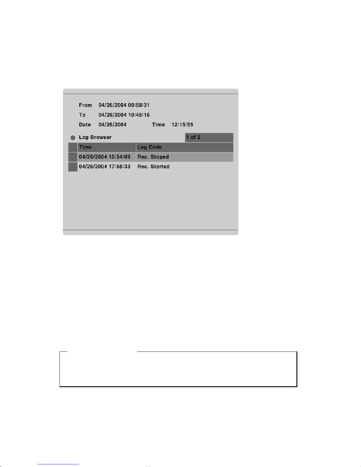
Search Mode is used to search and play specific data directly during playback mode. Data can be
searched by specific Time and Date or by the Event Log browser.
From: First saving time
To: Last saving time
Select From/to and then Press [Enter] button
Button control
- Press the [SEARCH] button during playback mode.
- Search for data by entering Date/Time or by selecting an event from the Event Log browser.
- Press the [ENTER] button after entering the desired Date/Time or selecting Event from log.
- The selected images will begin to playback.
- To exit from search mode, press the [EXIT] button.
<Note> Using Log Browser
1. To move to the previous/next page, press the "Left" or "Right" buttons.
2. To move to previous log entry, press the "Up" button.
3. To move to next log entry, press the "Down" button.
18
Page 19
4.3. Copy / Backup / Delete data manager
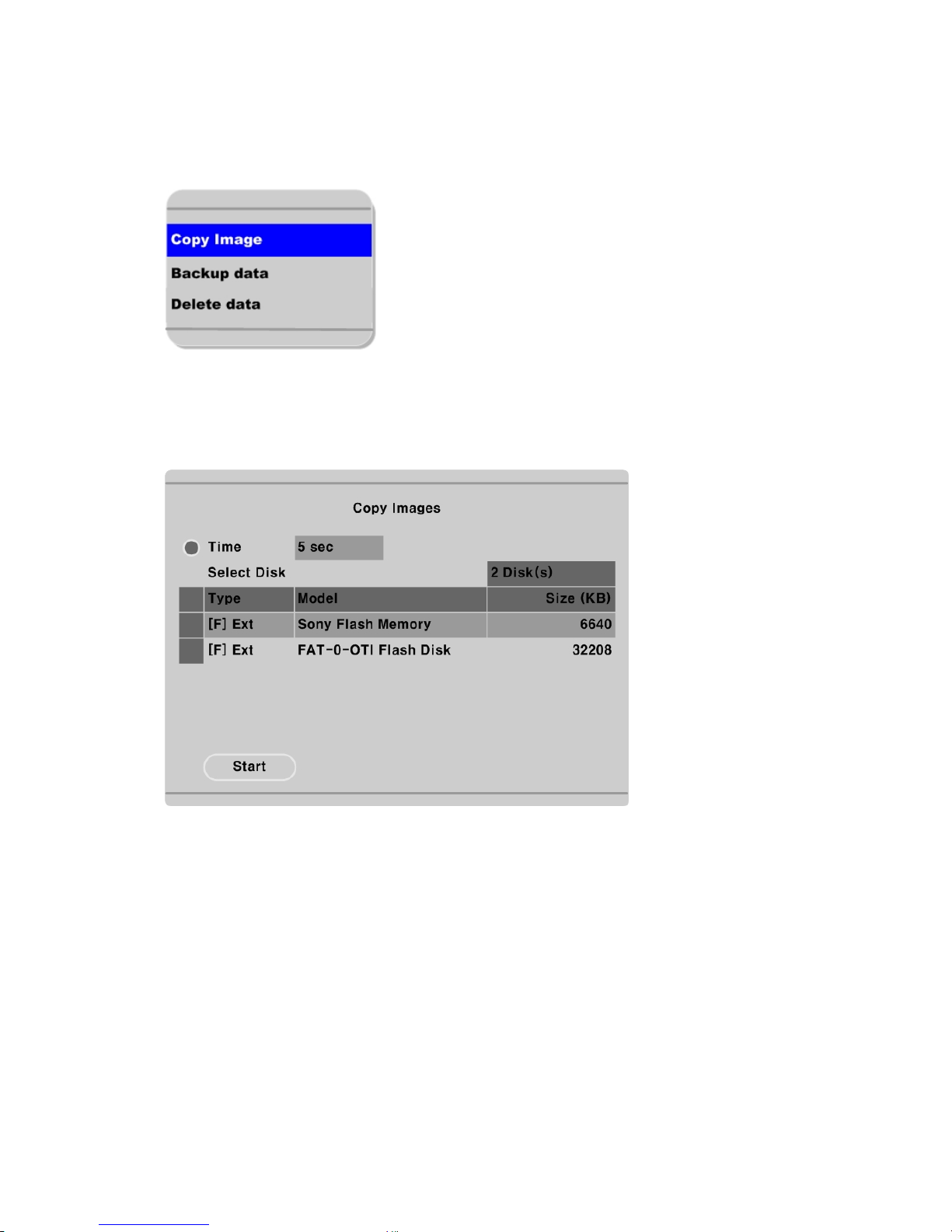
To copy/backup/delete the recorded data. This menu is activated during playback mode.
- Press the [SELECT] button and [MENU] button in Playback mode.
4.3.1. Copy image
To copy a specific data with USB memory stick.
Time
To designate copy range between 1sec and 1 hour.
Select Disk
Select copy disk.
19
Page 20
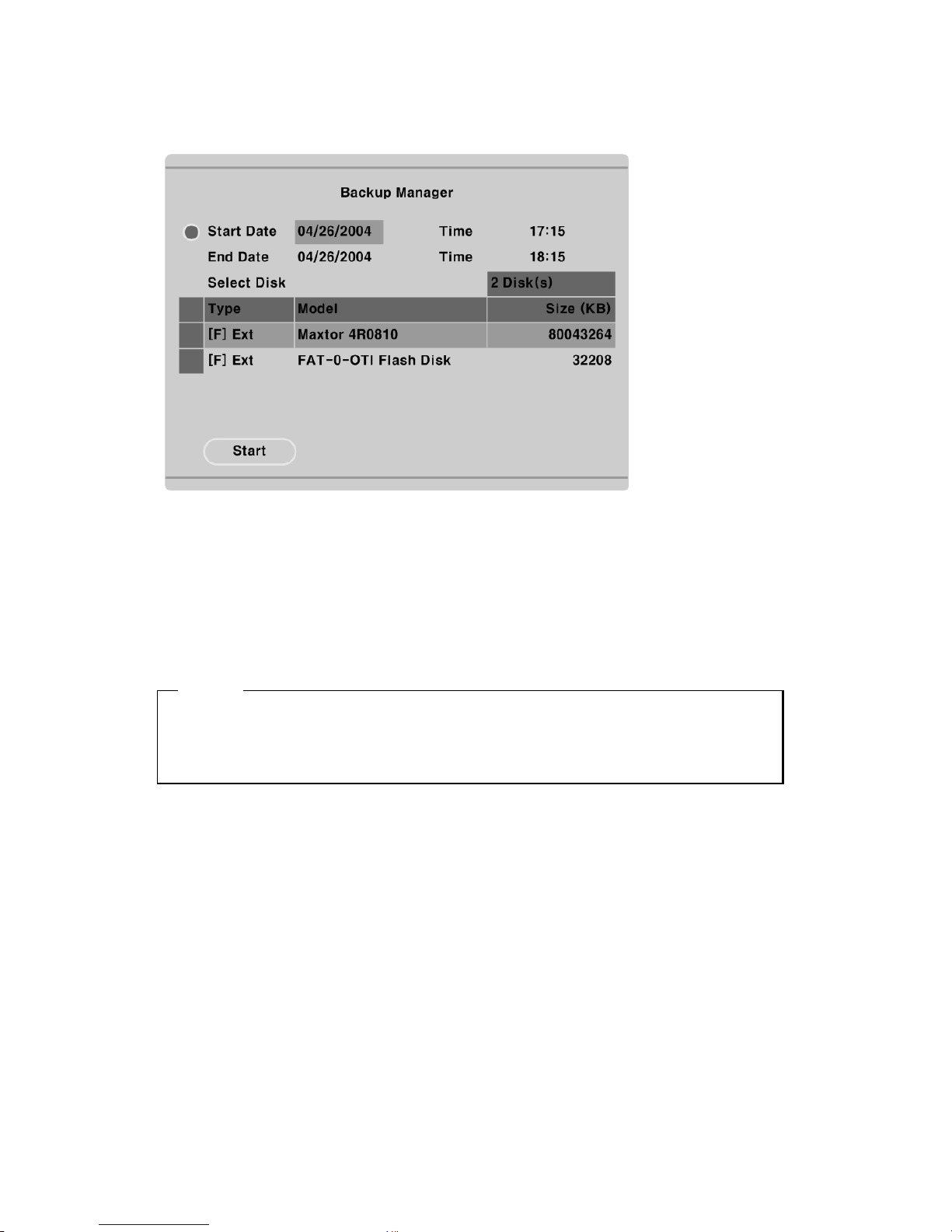
4.3.2. Backup manager
Start Date & Time / End Date & Time
To designate backup range.
Select Disk
To select which storage will be used as backup device. To change the disk status, use the “Disk Manager”
menu under the “System” tab.
<Note>
Backup Manager does not support USB devices. Backup Manager will ONLY work with devices
connected through IEEE1394 / FireWire ports.
CD-R Media have to use above 700MB, Copy file Extension is re4, Backup file Extension is vfs3
20
Page 21
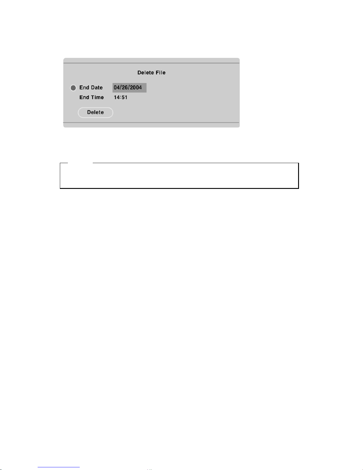
4.3.3. Delete data
To delete a specific file range from the current recording HDD. This menu does not affect backup disk.
The beginning of the range is always the beginning of the recording on the HDD.
<Note>
One block size of HVR File system is 64MB, so if you delete data , it couldn’t be delete exact time,
because data delete is operate by block.
21
Page 22

5. Configuration
5.1. Quick setup
There are three menus for recording setup; Quick setup, Recording, Alarm recording menu in
Configuration Menu. Quick setup is the easiest set-up, activating all four analog cameras to record with
the same settings and conditions. Recording is the standard recording settings and can be customized
based on time and channel. Alarm recording is the recording schedule based on alarm conditions (Motion
Detection, Sensors, etc.) Also, Quick Setup has time setting menu.
5.1.1. Date/Time
When HVR-04 is manufactured in factory, time zone will be set as “GMT + 9:00”.
Set the time to local time zone.
Changing HVR-04 time may cause time conflict with recorded images. In this case, it is strongly
recommended to re-format the hard drives after making changes.
Button control
- Press [MENU] button on HVR-04 front panel.
- Move to “Quick Setup” menu (First tab on the Configuration menu).
- Move to “Date/Time” below “Quick Setup” using downward arrow button on HVR-04 front panel.
- Press the [ENTER] button on HVR-04 front panel.
- Set time. (The following picture will be displayed when setting time menu)
- In order to access each menu, press [ENTER] button after selecting it with upward/downward
arrow button on HVR-04 front panel.
22
Page 23
Time Zone
Set the time zone using the left/right arrow button on HVR-04 front panel. Every time you press left/right
arrow button, time zone will change. Select the desired time zone. (To move to the previous menu, press
[EXIT] button on HVR-04 front panel.)
Daylight Saving
The Daylight Savings option is linked to Time Zone. Daylight Savings is only activated for time zones
that use Daylight Savings. For example, selecting GMT – 7:00 Arizona will disable the option for
Daylight Savings because Daylight Savings is not used in Arizona. This menu is linked with “Time Zone”
menu. Namely, if selecting daylight saving area in time zone, this menu will be activated. Oppositely if
selected time zone is not enforced, it will not be. It is based on MS Windows. So this menu is for setting
whether you apply ON/OFF (with left/right arrow button on HVR-04 front panel) in daylight saving area.
Sync with NTP
Setting up Sync with NTP(Network Time Protocol).
<Note>
Please refer to the Configuration of “NTP Settings”.
23
Page 24
Time Format
Set the time format between “MM/DD/YYYY” and “YYYY/MM/DD” using the left/right arrow button
on HVR-04 front panel.
Date/Time
Set date and time. To move from Month to Day to Year/Hour to Minute, use the left/right arrow buttons.
To select each month, each day, etc, use the up/down arrow buttons.
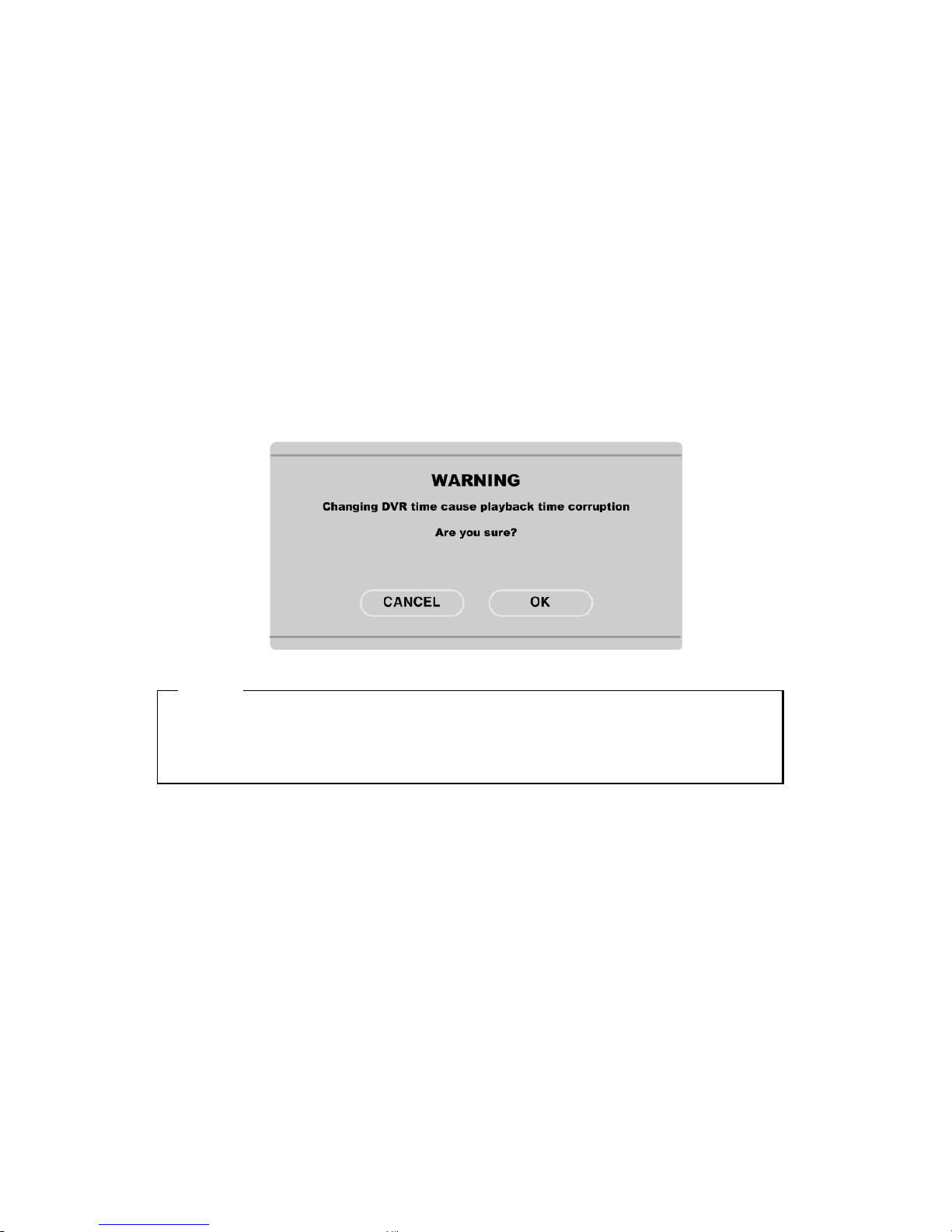
Apply Date/Time
Press this button to confirm the above settings. An window will pop-up warning of the possibility of time
conflict with recorded images. It is strongly recommended to format the HDD after making changes to the
time menu.
<Note>
Most setting values are applied automatically, when exiting from the related menu page. But “Date” &
“Time” settings are not applied automatically because they may critically affect the file system of the
recorded HDD. To apply Date/Time settings confirm settings with [Apply Date/Time] button.
24
Page 25
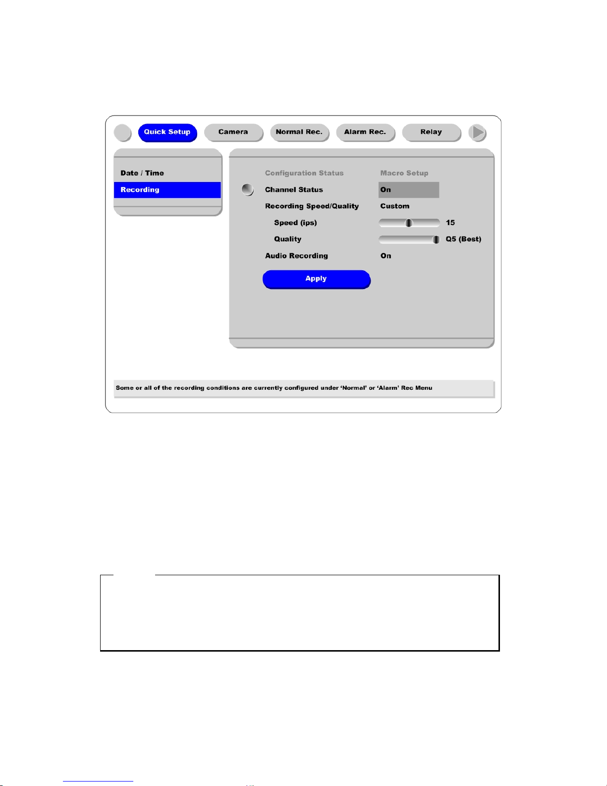
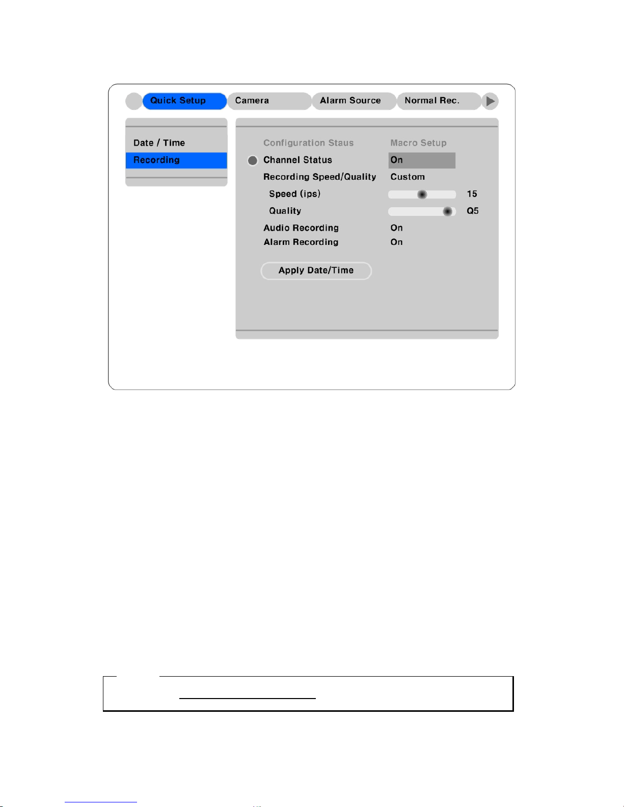
5.1.2. Recording
Its recording values are applied to all 4 channels for all time periods.
Button control
- Press [MENU] button and select to “Recording “ from the “Quick Setup” tab.
Configuration Status
Displays the recording setup status. If recording is configured with the Quick Setup, “Macro Setup” will
be displayed. If recording is configured with the “Normal” and “Alarm” recording, “Custom Setup” will
be displayed.
<Note>
1. When IP channel is 'Off' and all 4 analog cameras' recording conditions are set identically, the status
is marked as 'Macro Setup'. Otherwise, it is marked as 'Custom Setup'.
2. When IP channel is 'On' and all 16 cameras' recording conditions are set identically, the status is
marked as 'Macro Setup'. Otherwise, it is marked as 'Custom Setup'.
25
Page 26

Channel Status
When “On,” all four analog channels will record based on the Quick Setup settings.
Recording Speed/Quality
There are four conditions (Low/Standard/High/Custom).
All conditions except “Custom” will synchronize “Speed (ips)” and “Quality” automatically; “Low”
setting is 1ips/Q5; “Standard” setting is 5ips/Q5; “High” setting is 15ips/Q5. When using the “Custom”
setting, Speed (ips) and Quality can be set separately.
Audio Recording
Enables the audio recording feature. If audio is set as “On,” and “Audio Synch with” is set as “All” (in
the “Audio” menu under the “System” tab) audio will be available in Playback Mode with all channels.
Apply
Confirms the Quick Setup Recording settings. HVR-04 will begin recording after pressing the “Apply”
button and exiting from the recording menu.
26
Page 27
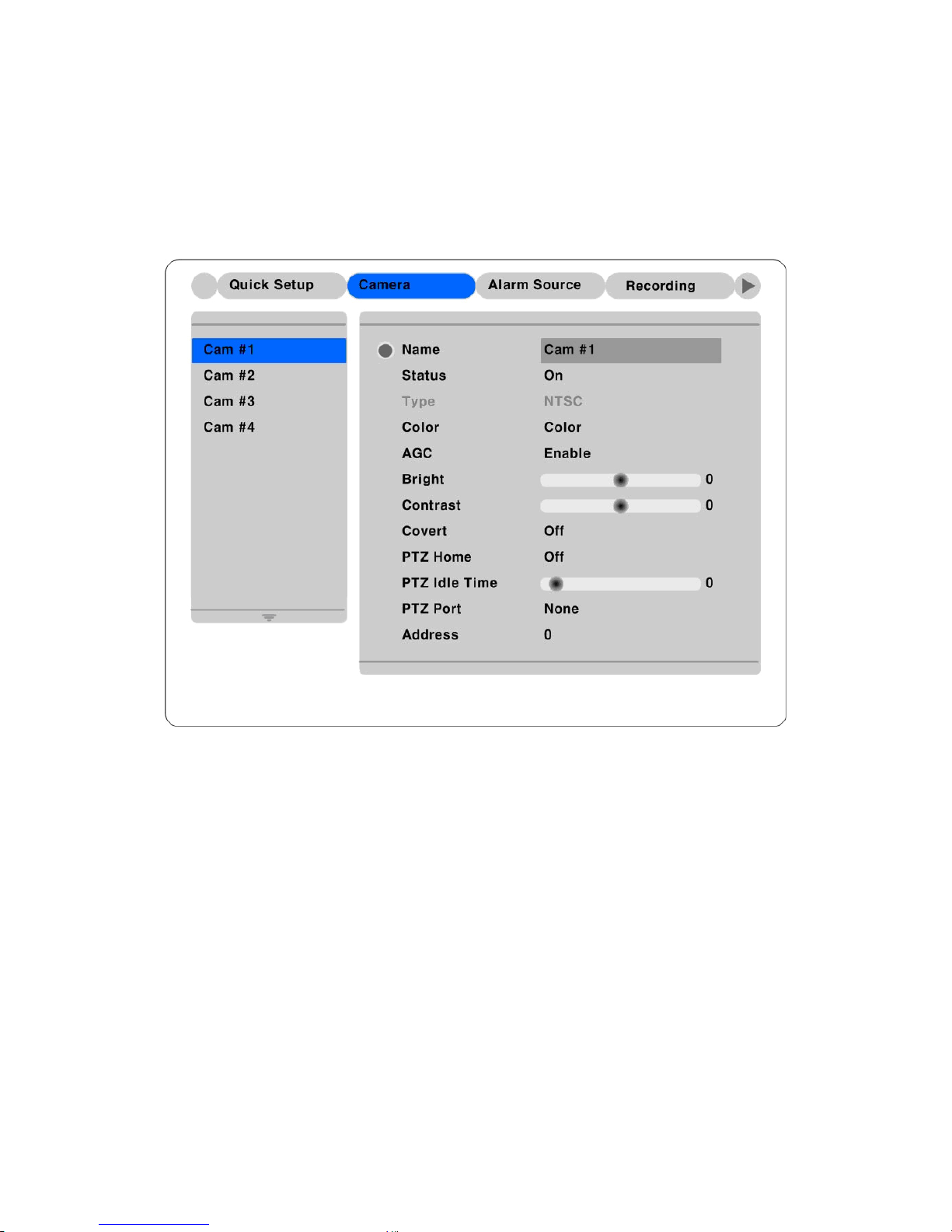
5.2. Camera – analog camera channels (Ch 1 ~ Ch 4)
This menu is for configuring individual cameras. In Quick Setup, camera status is automatically set as
“On.” Settings such as Brightness and Contrast can be set for each channel. The values assigned will
apply for both monitoring and playback modes.
Button control
- Press [MENU] button and use the [ARROW] keys to move to each channel below the “Camera”
tab.
Name
Assign a customized name to the channel.
Press [ENTER] to open the necessary dialogue box.
27
Page 28
<TIP>
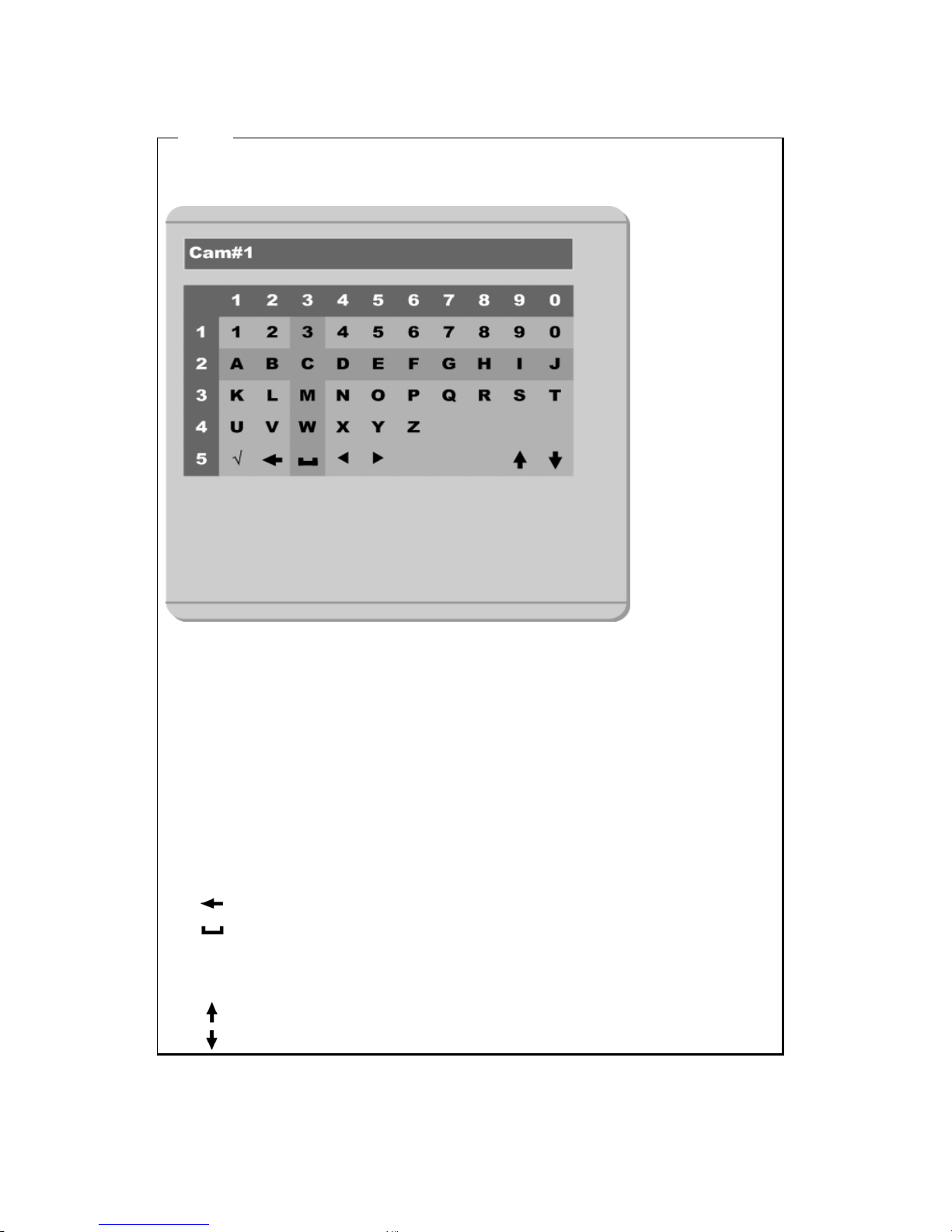
When assigning a name to a channel, the following dialogue box will appear. This box is also used later
in the system, but the method is always the same.
- To select a letter, use the [ARROW] (◄◄ and ►► ) buttons or the number buttons on HVR-04
front panel; “0” to ”9". When using the [ARROW] buttons, use the [PLAY] (►) button to
select each choice.
- The intersection between the horizontal and the vertical bar is the selected choice.
- Press the ► button to confirm the selected value.
- Or enter the related numbers in order of horizontal/vertical. (For example, in order to select “C”,
press [3] and [2] button.)
- After setting all values, press the [Exit] button.
- Function Key
9
: Enter
: Back Space & delete
: Space
◄ : Left
► : Right
: Previous Code Page
: Next Code Page
28
Page 29

Status
Set “On/Off” using the ◄◄ or ►► buttons after pressing the [ENTER] button.
Type
Displays the video-input signal. NTSC is the signal used in North America. To toggle the setting, use dip
switch on the rear panel of HVR-04.
For each of the following settings, use the [ENTER] button to access the setting, then the [ARROW]
buttons to change the values.
Color
Set “Color/ B/W” using the ◄◄ or ►► buttons.
Gain/Brightness/Contrast
Set the value between –9 and +9 using the ◄◄ or ►► buttons.
Covert
It is possible to Monitoring On/Off.
If you set On, you can’t see monitoring channel.
PTZ Home
If you do not operate while PTZ Idle Time, It will move to preset #1 position
PTZ Idle Time
Set PTZ Operating Time, If you set 20 Sec after 20sec it will go to preset #1 position.
PTZ Port
Set the value using the ◄◄ or ►► buttons.
Address
Press the [ENTER] button to open the dialogue box.
29
Page 30
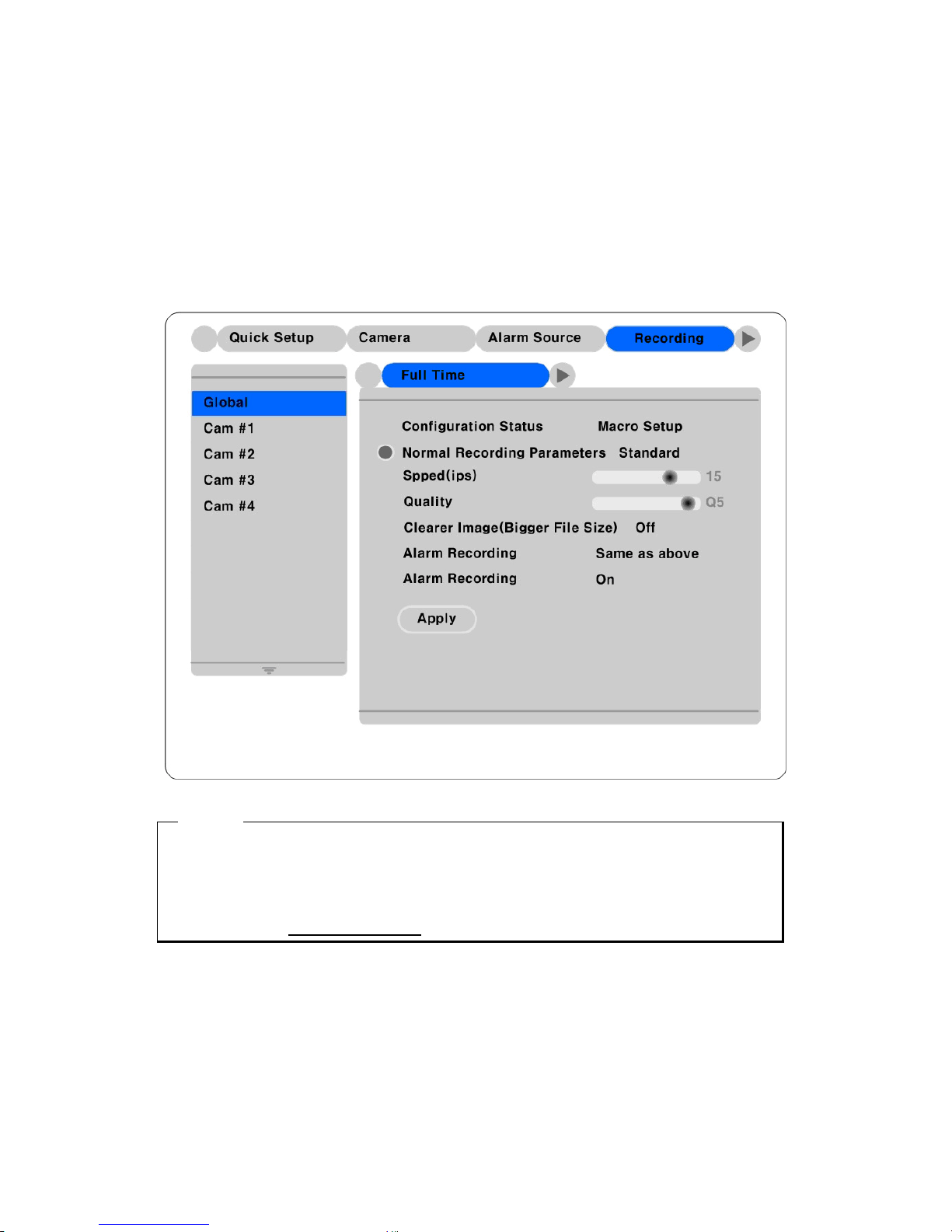
5.3. Recording – analog camera channels (Ch 1 ~ Ch 4)
Recording - This menu is for configuring the recording settings based on channel and timetable. If this
menu is configured Quick Setup, the previous Quick Setup values will be replaced by the Recording
settings.
5.3.1. Global setting
Almost similar with Quick Setup, it will be setting up all of analogue channel same condition every hour.
<Note>
1. There is no audio recording configuration, you could be setting up Special Time Recording and Event
Recording
2. You must click “Apply” button for confirm.
3. Please refer to the
Each Channel setting
30
Page 31
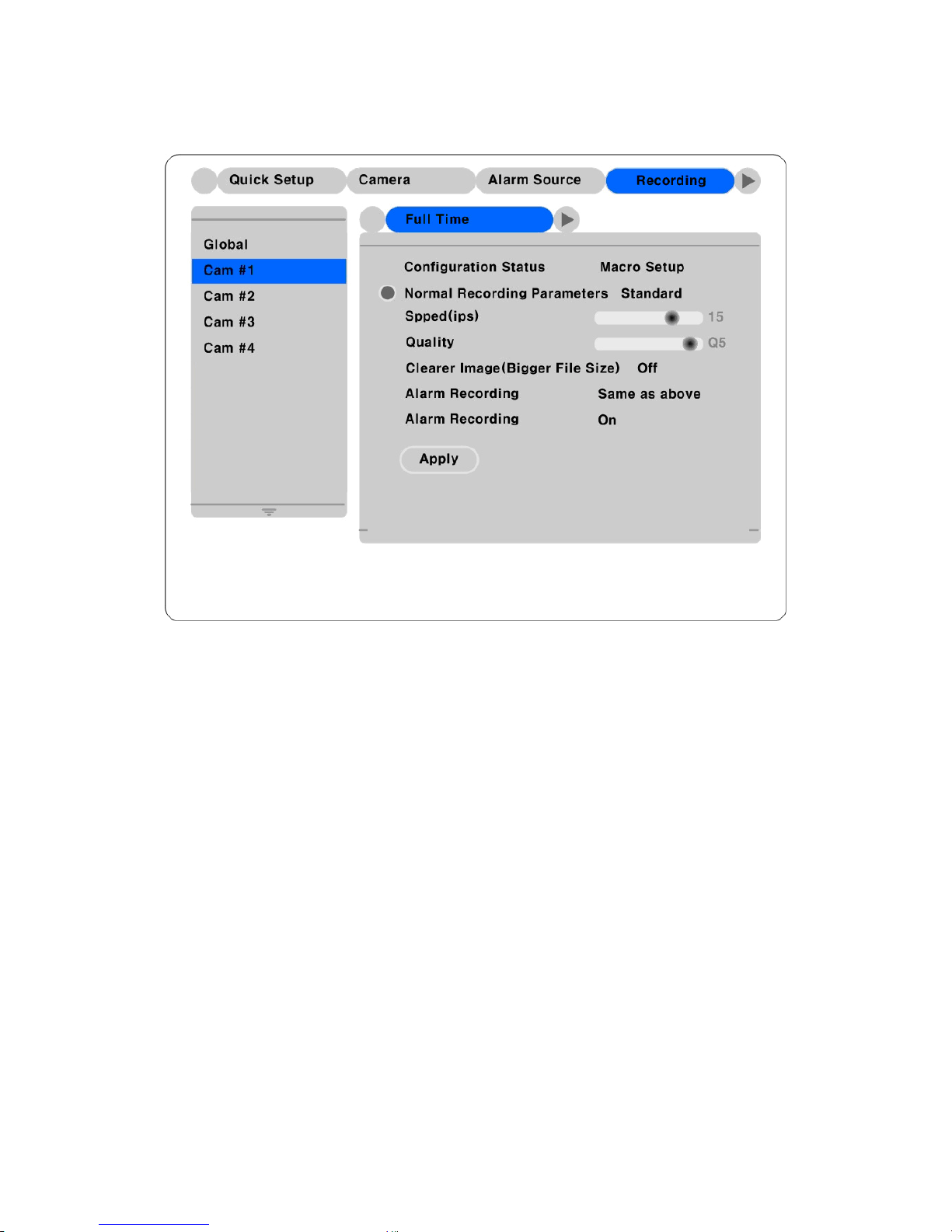
5.3.2. Each channel setting
Time Schedule
Each camera can be set to record based on four time schedules; Weekday (Day) / Weekday (Night) /
Weekend (Day) / Weekend (Night). Each schedule can be configured under the “System” tab.
31
Page 32
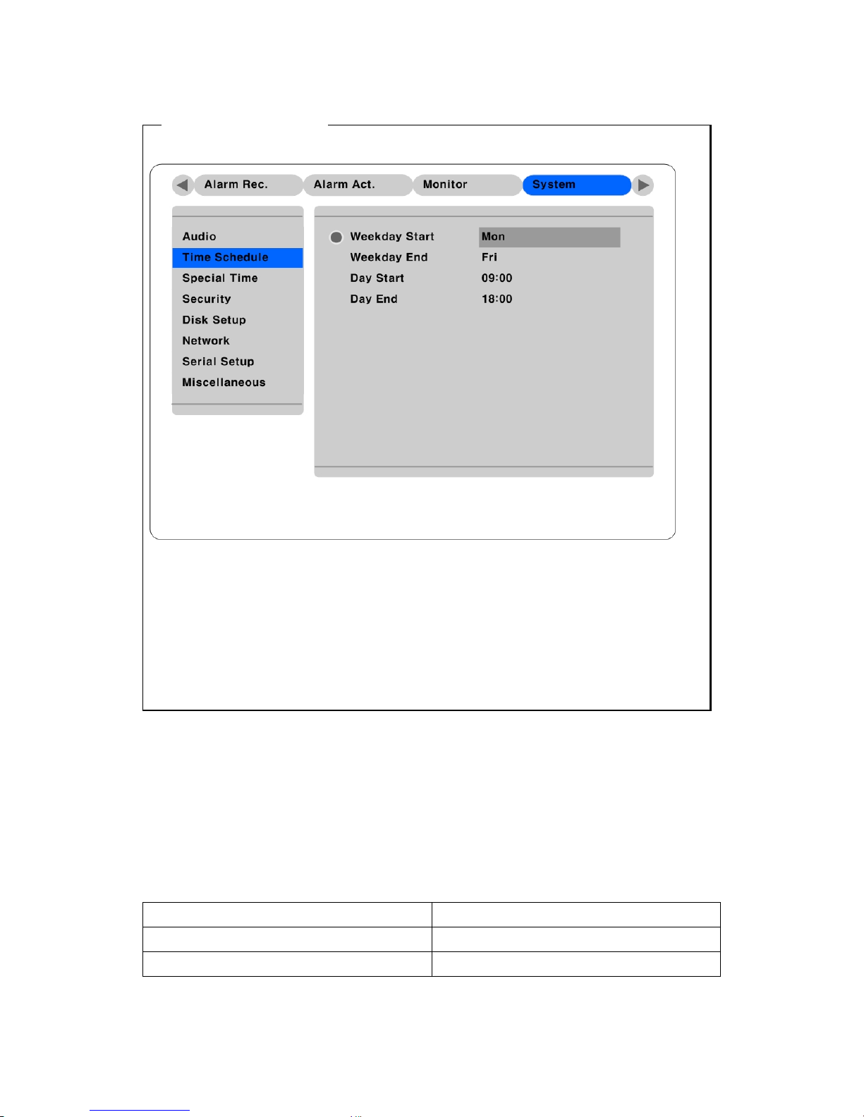
< Setting Time Schedule >
In order to set time schedule, move to “System” menu.
Weekday Start/End
Press [ENTER] to access the Time Setting. Set the range for “Weekday” between Monday and Sunday
using the ◄◄ or ►► buttons. “Weekend” is set automatically based on “Weekday” range.
Day Start/En d
Set the range for “Day” using the up/down buttons. The “Night” range is set automatically based on
“Day” range.
Recording Speed/Quality
There are five conditions; No Rec./Low/Standard/High/Custom.
All conditions except “Custom” synchronize “Speed (ips)” and “Quality” automatically; “Low” setting is
1ips/Q5; “Standard” setting is 5ips/Q5; “High” setting is 15ips/Q5. When using the “Custom” setting,
Speed(ips) and Quality can be set separately.
Maximum recording speed is restrict as like a below table.
HVR-04(Maximum 60ips)
2 Channel 30 ips
4 channel 15 ips
32
Page 33

Clearer Image Mode
This menu is to recording highest image quality, if you setting up On mode, you could be recording
clearer image without ghost. But recording size will be increasing 2 to 20 (comparative to recording).
Also defends on the recording condition frame rate will be decreasing
Special Time Recording
This menu is to designate different recording conditions during “Special Times.” “Special Time” is
designated under the “System” tab.
There are five conditions; No Rec/ Low/Standard/High/Same as above.
33
Page 34
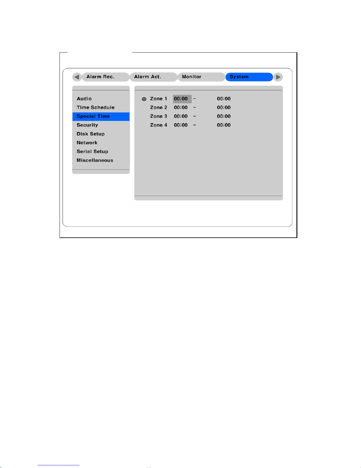
< Setting Special Time >
To set ”Special Time,” move to “System” tab.
Up to four zones can be designated as “Special Time.”
Event Recording
Press the [ENTER] button to access the Event Recording feature. Set “On/Off” using the ◄◄ or ►►
buttons.
Event recording condition is set under the “Alarm Recording” tab.
This setting is used to configure the HVR-04 to record data according to an alarm condition, such as
Motion Detection (MD), sensors, etc.
34
Page 35
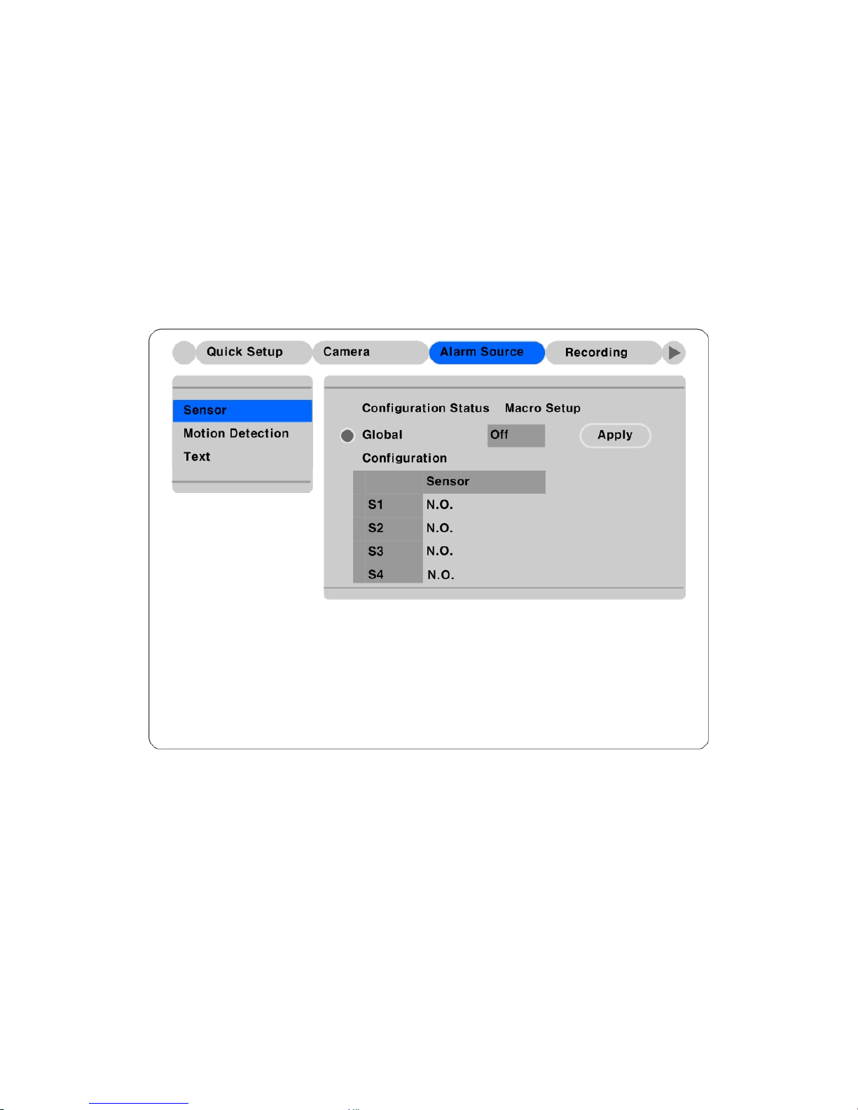
5.4. Setting alarm recording.
This menu is to configure for the settings for alarm recording conditions. To activate this schedule, set
“Event Recording” under the “Recording” tab to “On.”
Also, before alarm recording, you must set “Alarm Source”
5.4.1. Setting sensor
This menu is setting up sensor input type.
Sensor will be support two type Normal Open (N.O.) and Normal Close(N.C.).
Global
You could be setting up all sensors in same condition, you have to choose Off/N.O/N.C and the click
“Apply:” button.
Configuration
You could be setup 4 each sensor. (S1 ~ S2)
35
Page 36
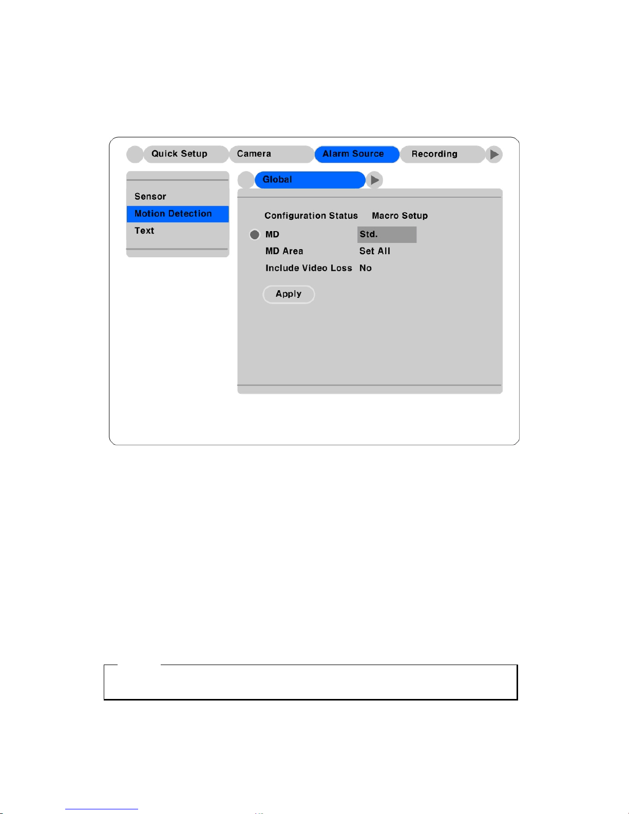
5.4.2. Setting motion detection
This menu is setting up MD for each channel. Global is setting up all channel of same condition (Cam
#1~Cam#16), also you could be setup each channel separately.
Motion Detection
Choose from among four sensitivity conditions; Off, Low, Standard, High., Highest.
MD Area
Set up of MD area. There consist of 64 blocks (8 X 8).
If you click “Set All”, you could be setup all of screen. Also Select “Clear All” to remove blocks from
detecting motion.
Include Video Loss
The HVR-04 will only work with NO (Normal Open) sensors. If sensors are connected, turn each sensor
“On.”
<Note>
If you setting up Global, you must be click “Apply” Button.
36
Page 37
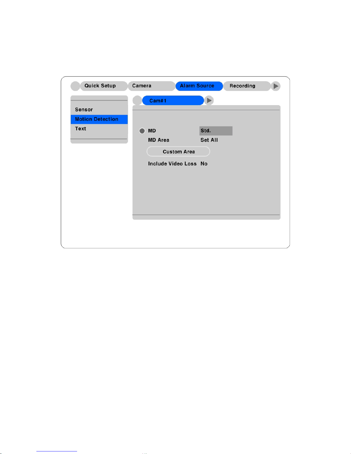
5.4.2.1. Setting motion detection per each channel
Setting up of each channel MD is same as Global setting, if you setting up each channel MD, you could b
e setting up MD block additionally.
Custom Area
User could be set up of MD area. It consists of 64 blocks (8 X 8).
Default value is “Select All”. Select “Custom Area”, MD area will be open.
37
Page 38
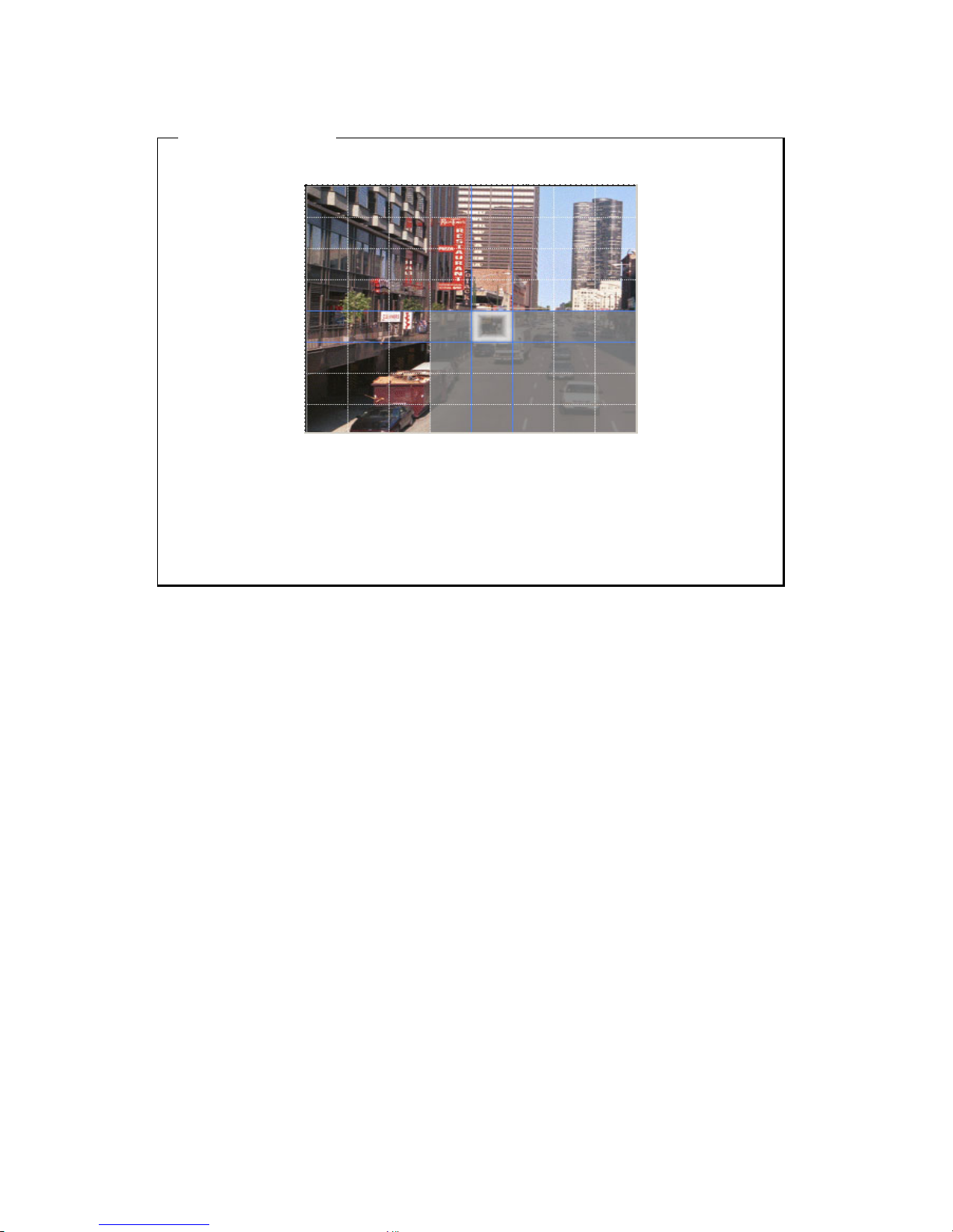
<Setting MD Area>
Designate a specific area for motion detection triggered event.
Press the “Custom Area” button, to customize the motion detection area. The area is divided into 64
blocks (8 X 8).
Selected MD area is indicated in dark gray. To remove blocks from motion detection, select the block
using the [ARROW] buttons and press the [ENTER] button. Press the [EXIT] button when finished.
38
Page 39
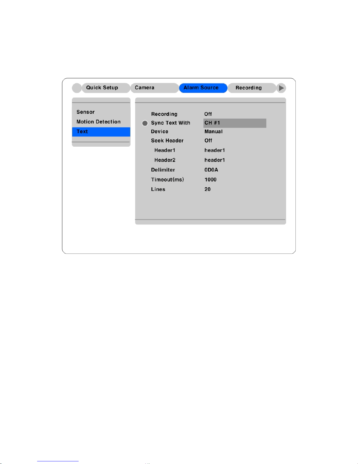
5.4.3. Setting text
In order to display or record text with image, it should be set OSD menu of COM1 part as
“SystemÆSerial setup”.
Recording
In order to make HVR-04 input text data, both of menus should be set as “On/off”.
Sync Text With
To set channel to synchronize with text
Seek Header
If a protocol is built in HVR-04 like Star Finger 007, this setting is needless. Otherwise, HVR-04 can’t
recognize which parameter value is input to HVR-04. Namely, all information has starting point and
ending point. Header means starting point that is always inserted. So when this header data is transmitted
to HVR-04, HVR-04 can recognize it as starting point. Two headers can be set maximally.
Delimiter
Because delimiter value may be different, refer to the manual of related device.
39
Page 40

Timeout(ms)
The following “Lines” means maximal text line that can be included within a data. However length of
each data may be different. Because HVR-04 can’t recognize it automatically, timeout menu is needed.
Namely, if specific time passes after HVR-04 receives the last line, HVR-04 will regard it as normal data
and decide to record.
Lines
To set maximal line of a data
40
Page 41
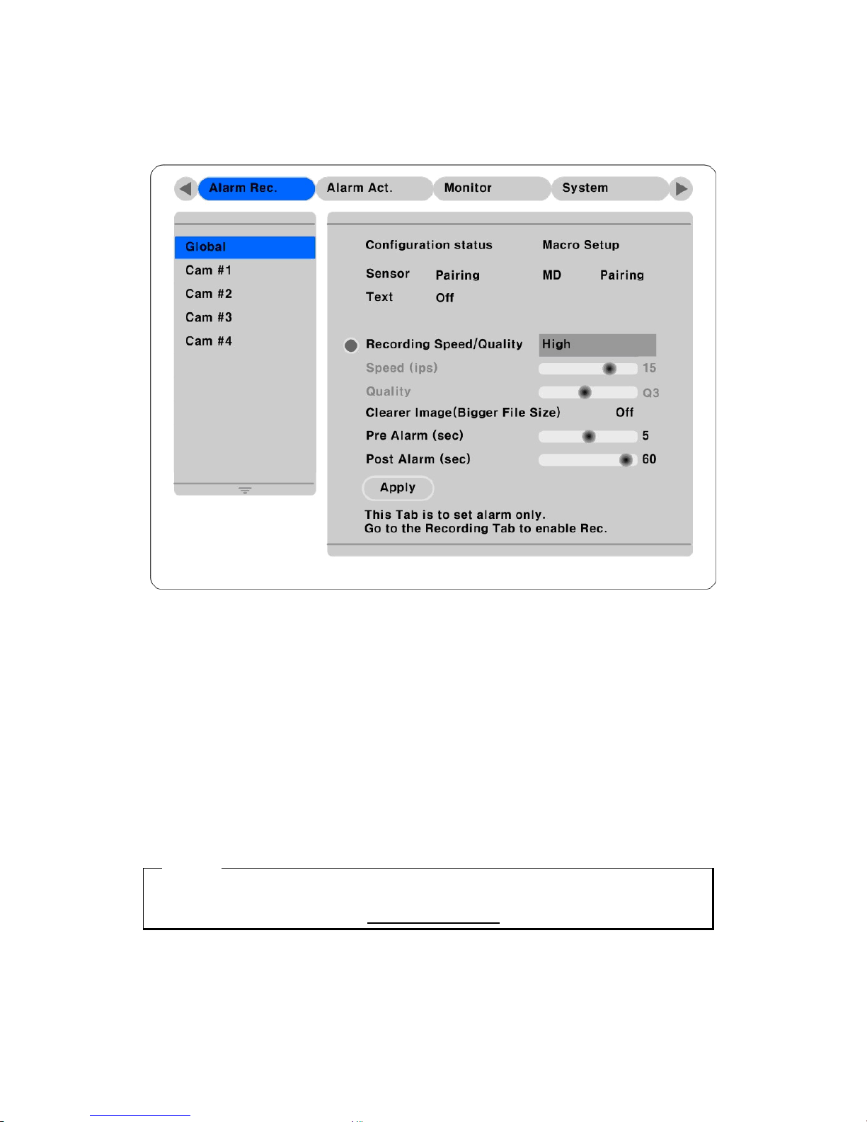
5.4.4. Setting global alarm recording
It was setting up same condition of all analog channels.
Sensor/MD
To set Sensor/MD alarm to synchronize.
Pairing means 1: 1 synchronize with Channel and Sensor/MD
Text
In case of setting "On" and input text, it was processed by Alarm Event and then saved
Clearer Image(Bigger File Size)
In Alarm Recording, you can set Clearer Image as On/Off.
<Note>
1. If you setting up Global, you must be click “Apply” Button.
2. Detail information, please refer to the each channel setting up
41
Page 42

5.4.5. Setting each channel
Alarm Source (*=All)
It is possible to text input 4 Sensor/MD throughout Alarm Source (IPCam : 16)
Sensor/MD selection is set under the “Number button”
Text selection is using arrow key and then select On/Off
In according to Alarm input, designate to PTZ Preset
<Note>
1. * : Press the “ENTER” button.
2. – or # : Press the number “0” button.
Recording Speed/Quality
There is four setting condition. (Low/Standard/High/Custom).
All conditions except “Custom” synchronize “Speed (ips)” and “Quality” automatically; “Low” setting is
1ips/Q5; “Standard” setting is 5ips/Q5; “High” setting is 15ips/Q5. When using the “Custom” setting,
Speed (ips) and Quality can be set separately.
Pre Alarm (sec)
Setting up maximum 10 sec
Post Alarm (sec)
Setting up maximum 60 sec
42
Page 43
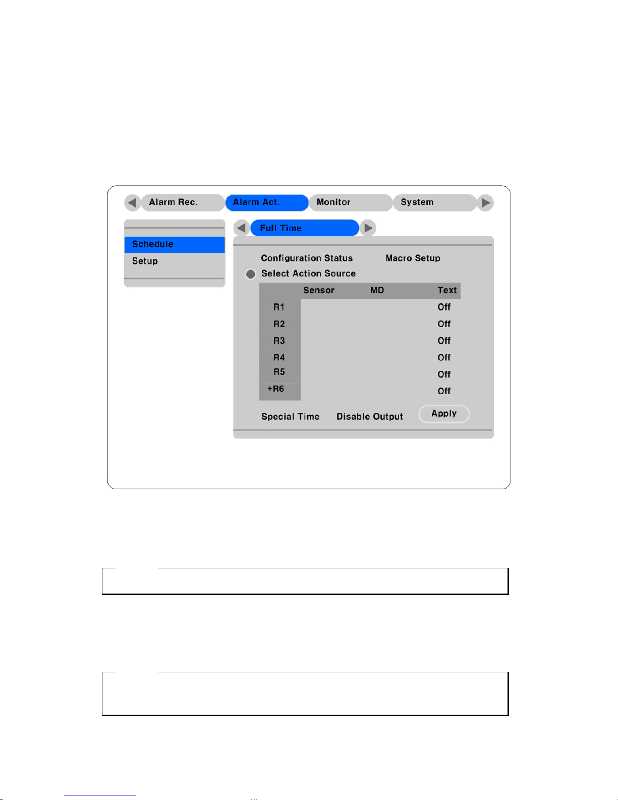
5.5. Alarm action.
This menu is to set the relay commands according to each time schedule. You could be set up five time
zone Full Time, Weekday(Day), Weekday(Night), Weekend(Day), Weekend(Night). After Set up
schedule, you have to set up relay, Buzzer, E-mail etc
5.5.1. Schedule
Select Action Source
Alarm triggered events (MD or Sensors) can be set to trigger Relays 1 through 4 or Any(Relay1 ~ Relay4,
Buzzer ,E-mail etc.), also It is possible to Text On/Off.
<Note>
1. ANY : Press the “ENTER” button.
Special Time
Enable “Special Time” to apply the relay schedule to the Special Time Zone.
<Note>
1. Global setting is setting up time schedule in same condition
2. If you setting up Global, you must be click “Apply” Button.
43
Page 44
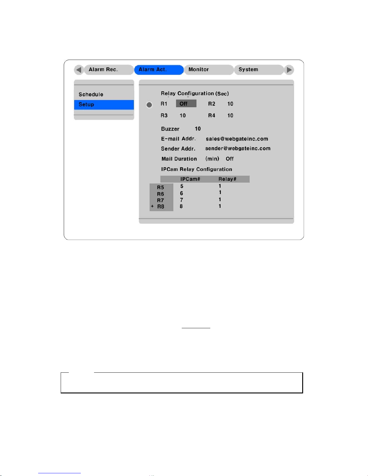
5.5.2. Setup
Relay Configuration
Set up its use of R1 ~ R4
Buzzer
Set up the condition of using Buzzer or not.
E-mail Addr .
Input E-mail address to receive alarm message.
Sender Addr .
Filing up E-mail sender’s item, E-mail form will be
who@where
Mail Duration (min)
E-mail Duration does not send a message every time, there is setting up time. And then periodically send
a message. (Possible to set up 1min to 30 min)
<Note>
If you using E-mail Duration, you have to set up DNS
IPCam Relay Configuration
You could be set up R5 ~ R16 of IPCam Relay.
44
Page 45

5.6. Monitor
Alarm Pop-up/Pop-up Hold(sec)
To set alarm pop-up screen. Pop-up duration time can be set between 5 and 10 seconds. If setting as
“Keep”, pop-up screen keeps holding. In order to cancel Keep mode, press another channel button.
Seq. Switching(sec)
To set sequence time between 1 and 60 seconds.
Auto-Flicker OSD
You could be On/Off Anti-Flicker form this menu.
Turn on the Anti-Flicker : Screen will be smooth and Flicker will be disappearing.
Turn off the Anti-Flicker : Screen will be sharp and Flicker will be appear.
Depends on the your monitor property, choose On/Off.
<Note>
After channel#1 is pop-up, if channel #2 is pop-up before pop-up hold time goes, it is divided into four
Screen and display channel #1 and #2.
Then from final pop-up time on hold time is automatically extended.(To maximum 8 channels)
45
Page 46
User Sequence Configuration
You could be edit auto conversion function by Users Mode.
<Caution>
1. Users Mode can be defined upto Maximum 16.
2. Above picture defined 6 sequence, 4 partition(1,2,3,4) Æ Full Screen(1) Æ 4 partition(5,6,7,8) Æ
Full screen(5) Æ Full screen(8) Æ 9 partition(9,10,11,12,13,14,15,16)
46
Page 47
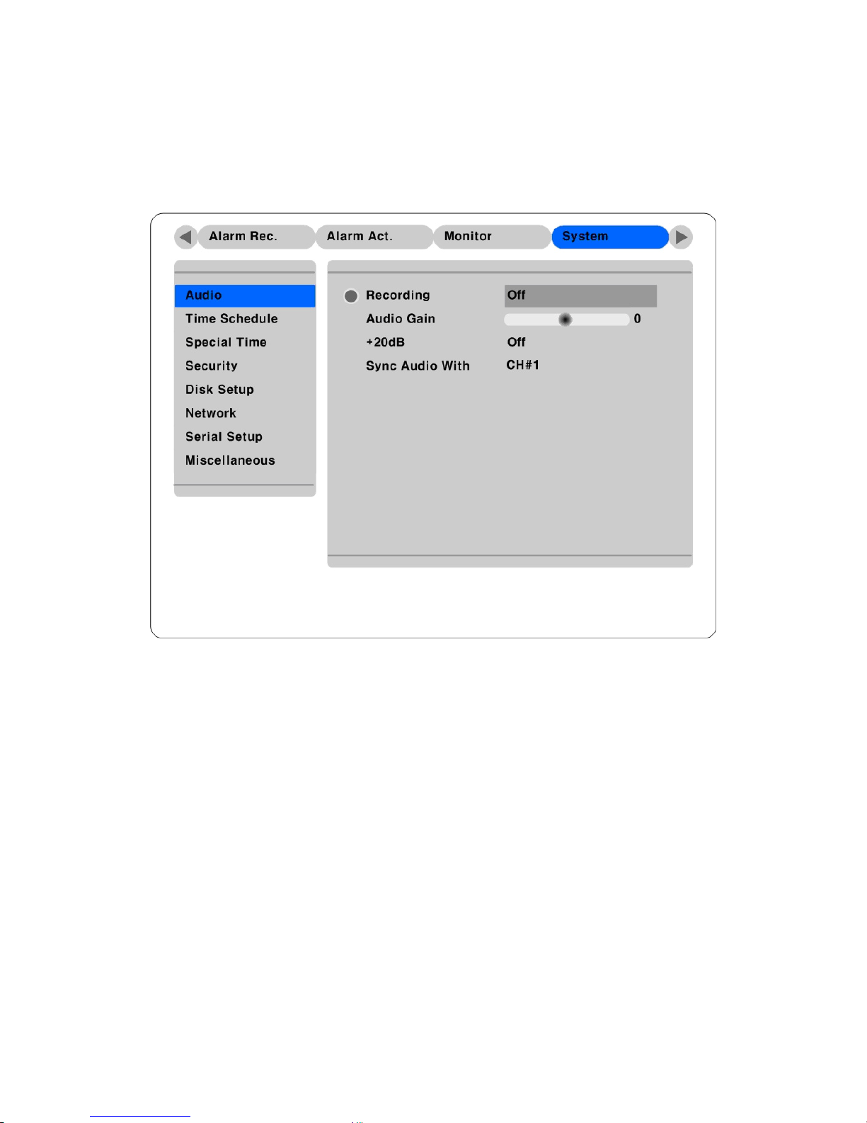
5.7. System
5.7.1. Audio
HVR-04 supports one channel audio input. This single audio channel can be replayed with any connected
channel or with all of them.
Recording
Set to “On” using the [ENTER] button and the [ARROW] buttons to record audio.
Audio Gain
Increases or decreases the sensitivity to the audio signal. Can be set between –7 and +8.
+20dB
To amplify the audio input signal. Should ONLY be used when using an external microphone.
Sync Audio with
Designate which channel(s) to synchronize audio with during playback.
47
Page 48
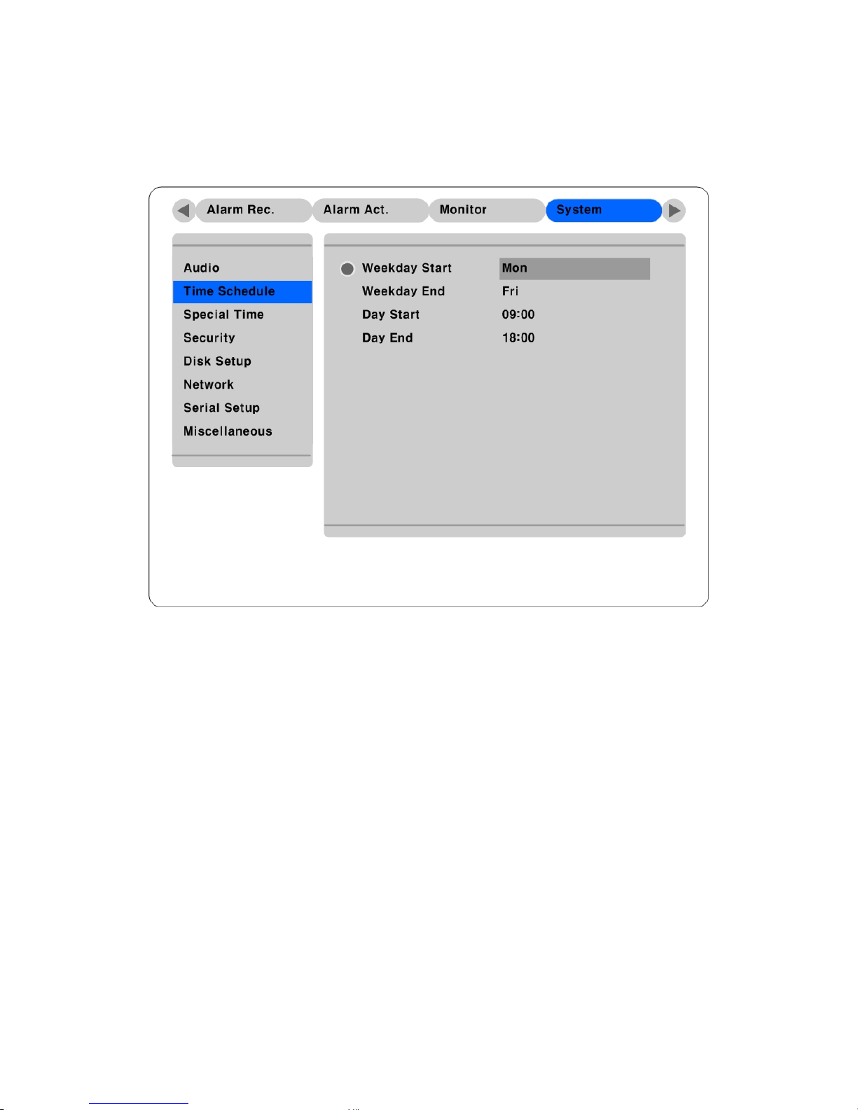
5.7.2. Time schedule
To designate Weekday/Weekend and Day/Night.
Weekday Start/End
Press [ENTER] to access the Time Setting. Set the range for “Weekday” between Monday and Sunday
using the ◄◄ or ►► buttons. “Weekend” is set automatically based on “Weekday” range.
Day Start/En d
Set the range for “Day” using the up/down buttons. The “Night” range is set automatically based on
“Day” range.
.
48
Page 49
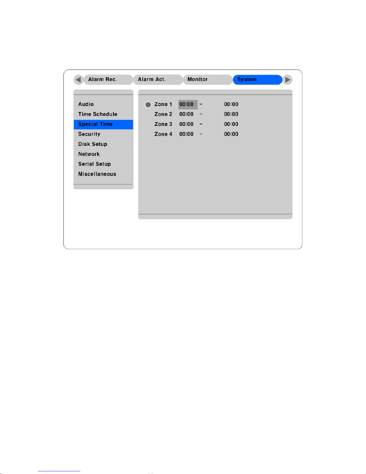
5.7.3. Special time
You could be set up specific time (for example lunch time, meeting time etc.)
Up to four zones can be designated as “Special Time.”
49
Page 50
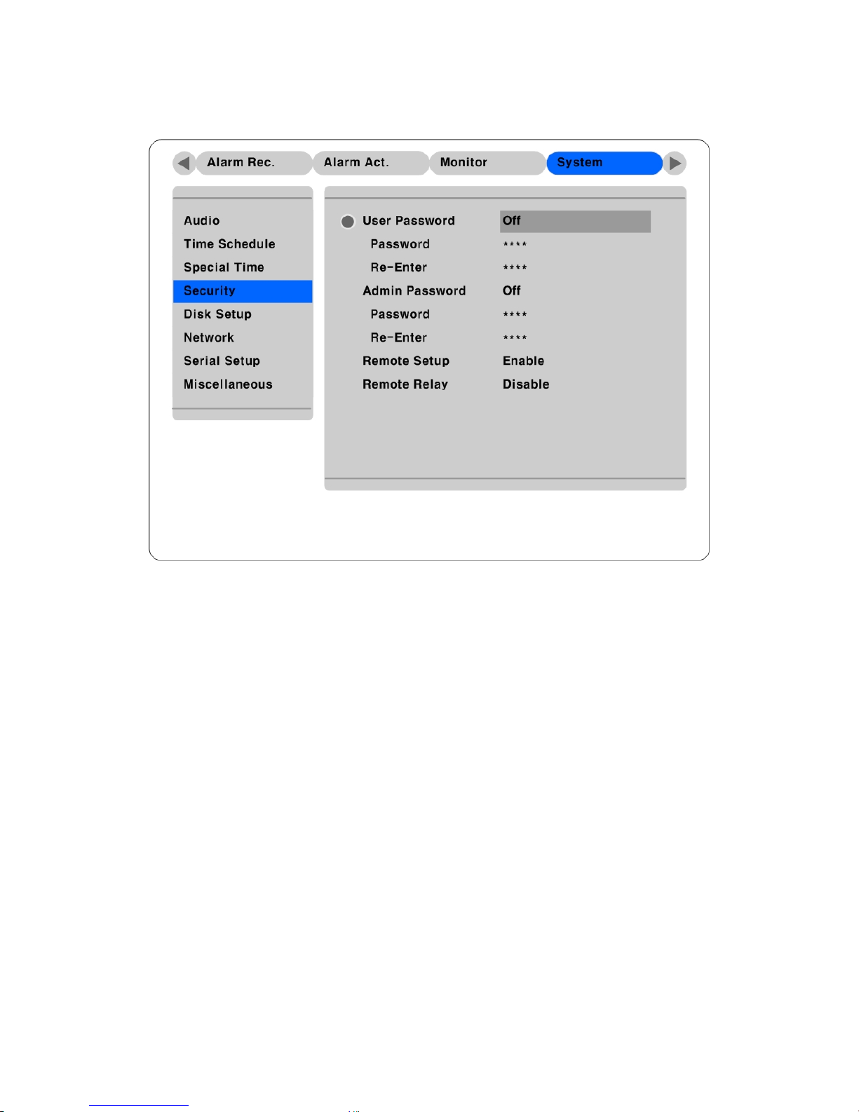
5.7.4. Security
User Password
Designate a User’s Password for access to monitoring and playback. Default password is “0000”.
Admin Password
Designate an Administrator’s Password to control access to Configuration Menu and full system control
authority. Default password is “9999”
Remote Setup
When set to “Enable,” users can configure HVR-04 through the S/W interface from a remote site via
network.
Remote Relay
Enables access to the “Relay” menu from a remote site.
50
Page 51
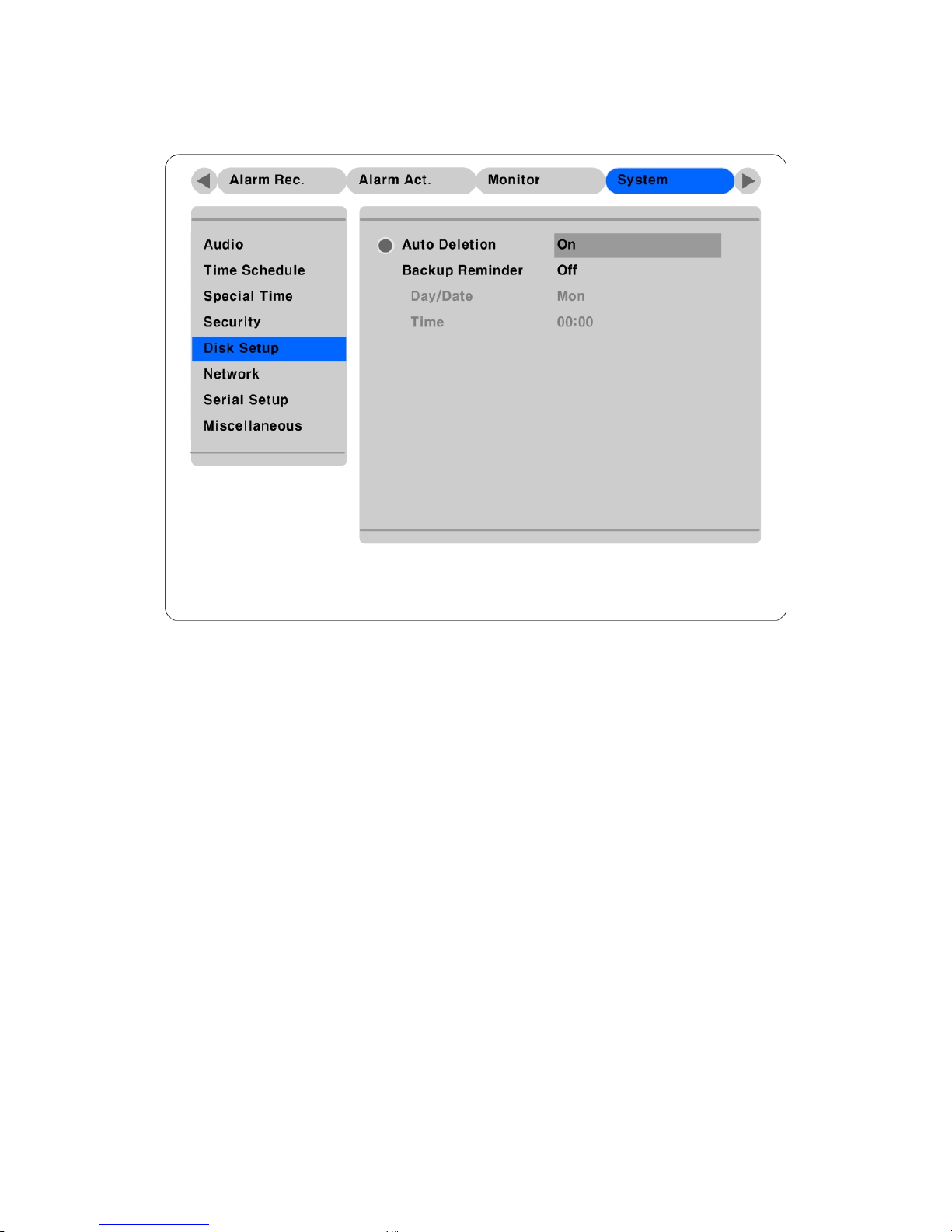
5.7.5. Disk setup
Auto Deletion
Images and data recorded under the “Normal” condition are automatically deleted as the hard-drive(s)
reaches capacity. Images are written over based on a first-in first-out basis.
Backup Reminder
A Backup Reminder can be set to remind users to backup the HDD. The reminder can be set to appear
daily, weekly, or monthly.
Day/Date/Time
To set the time for the Backup Reminder.
51
Page 52
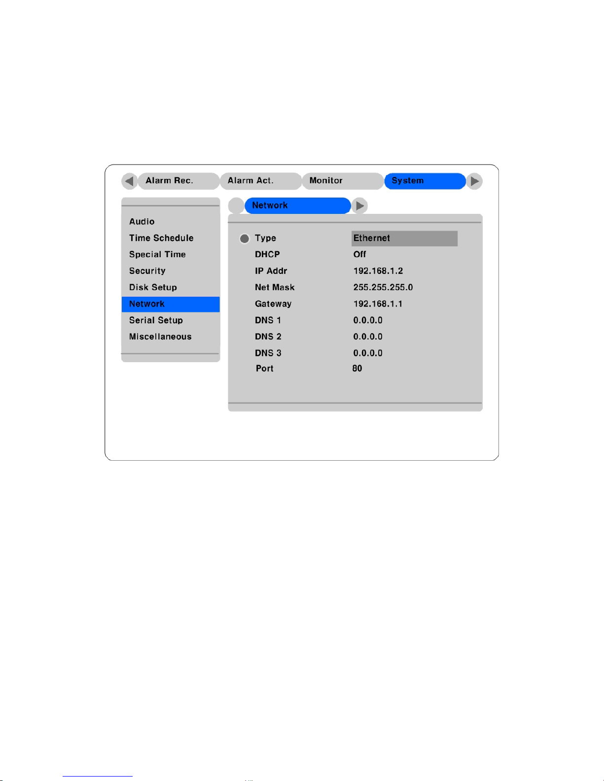
5.7.6. Network
There are four sub-menus; Network, xDSL, WRS, and Port Setting.
5.7.6.1. Network
This page is to define network type and set network addresses forHVR-04.
Type
This is to select proper network interface (Ethernet/xDSL) with which HVR-04 is connected. If HVR-04
is connected with Internet dedicated line, cable modem line or on LAN environment, select network
interface as ‘Ethernet.’
If HVR-04 is connected on xDSL line that needs PPPoE process to connect to the Internet, administrator
should select ‘xDSL.’ However, if the xDSL line does not need PPPoE process, administrator should
select ‘Ethernet,’ even though HVR-04 is connected on xDSL line.
DHCP
Basically, this menu is for the lines that have Ethernet interfaces such as Internet dedicated line, cable
modem line and LAN. If administrator activates ‘DHCP’ menu, all addresses are set automatically by
HVR-04 detecting them from DHCP server of your ISP. The detected addresses are not displayed on the
screen. The addresses do not need to be entered manually unless ‘DHCP’ is disabled.
52
Page 53

DHCP can also be used for xDSL (PPPoE) interface. Sometimes, all computers on a Local Area Network
(LAN) share a single Floating / Dynamic IP address. In this case, the HVR-04 should be assigned a
private IP address and have DHCP enabled. Users on the LAN can connect to the HVR-04 using the
private IP address and outside users can connect to the HVR-04 over the Internet.
IP Address, NetMask, and Gateway Address, DNS, Port
Administrator may configure IP address, Network Mask, Broadcast address, Gateway, DNS addresses
and Port of HVR-04.
53
Page 54
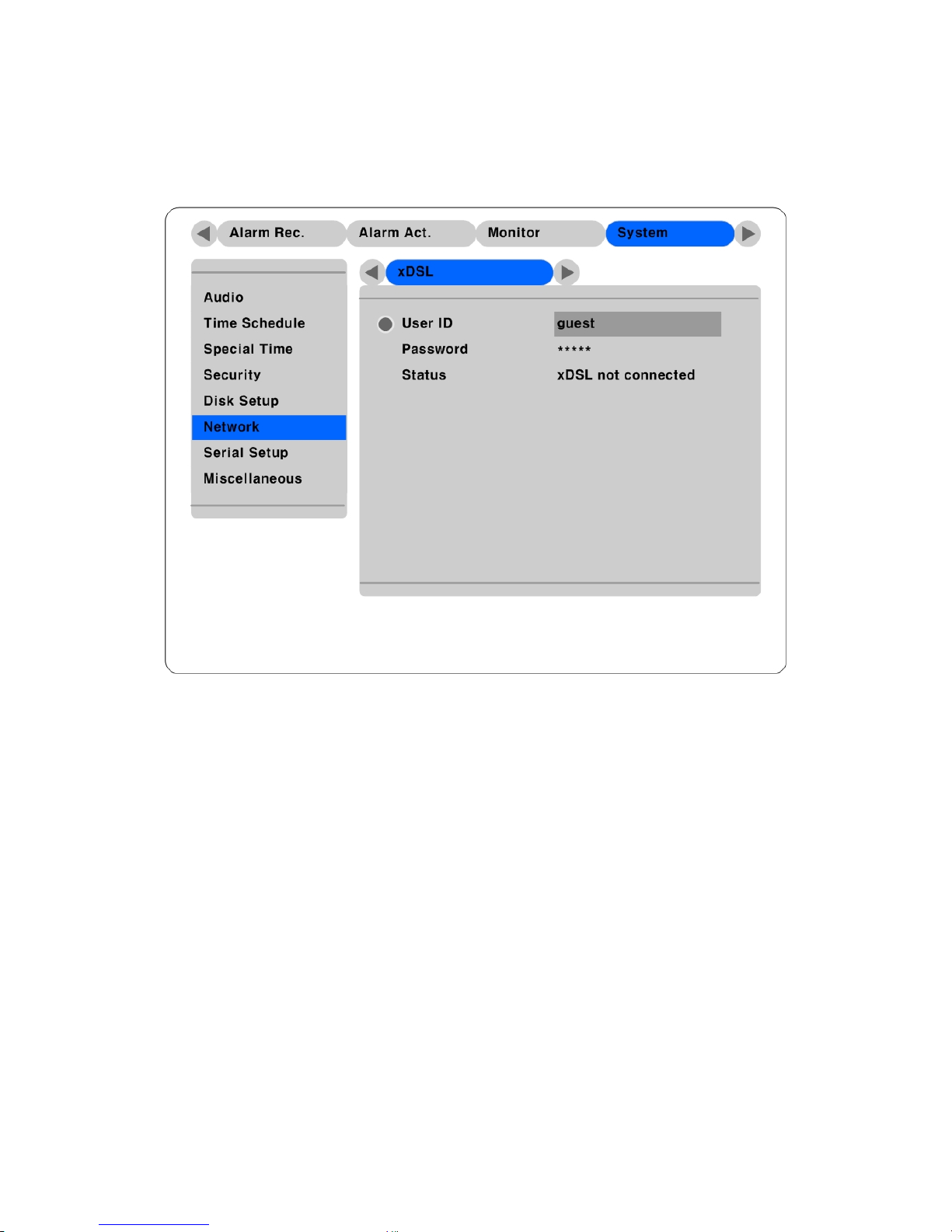
5.7.6.2. xDSL
If HVR-04 is connected on xDSL line and needs PPPoE process, the network administrator should
configure the user ID and password for PPPoE. ID.
User ID/Password
When HVR-04 is connected to xDSL, access ID and Password should be entered.
Status
Displays the HVR-04 connection status.
54
Page 55
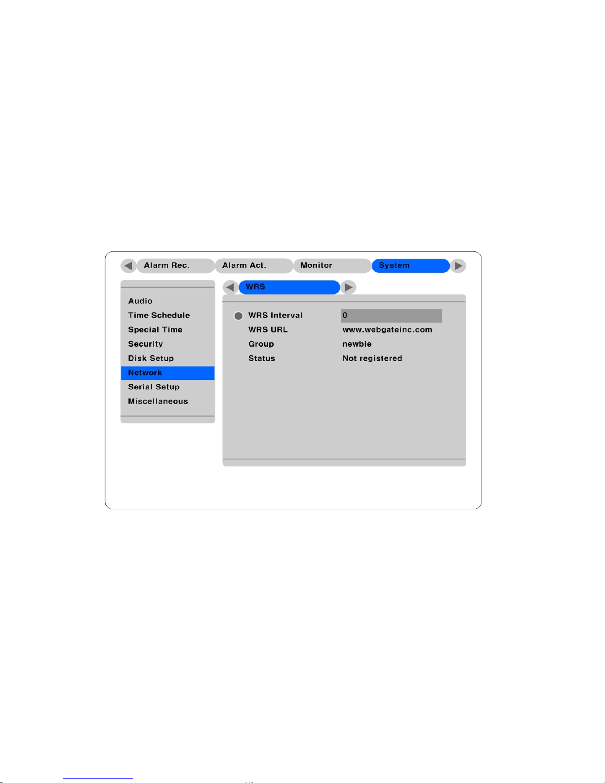
5.7.6.3. WRS
When a HVR-04 is installed under the environment of Cable Modem or xDSL Modem connection, its IP
address changes whenever it reconnects to the Internet Service Provider (the HVR-04 has a Dynamic or
Floating IP address). In this case users who don’t know the changed IP address cannot get access to the
HVR-04. HVR-04 with dynamic IP should be registered to the HUNT ELECTRONIC Registration
Server (WRS) server in order to make it easy for users to find the changed IP address, when they want to
access the HVR-04.
To register dynamic IP address to WRS, configure the descriptions below. If using xDSL modem or Cable
modem, configuration should be the same.
WRS Interval
WRS Interval should be set at 3600 seconds. This designates the frequency the HVR-04 will update
information to the WRS. If the interval is set lower than 3600 seconds, HUNT ELECTRONIC cannot
guarantee connectivity. If the WRS received too many updates, it may close the connection to the unit.
The WRS maintains registered units on the server list for two days. If no signal is received before two
days, the WRS will delete the unit from the register.
WRS URL
This is to configure a server address for registration. WRS address of HUNT ELECTRONIC Inc. is
“www.HUNT Electronicinc.com”.
55
Page 56
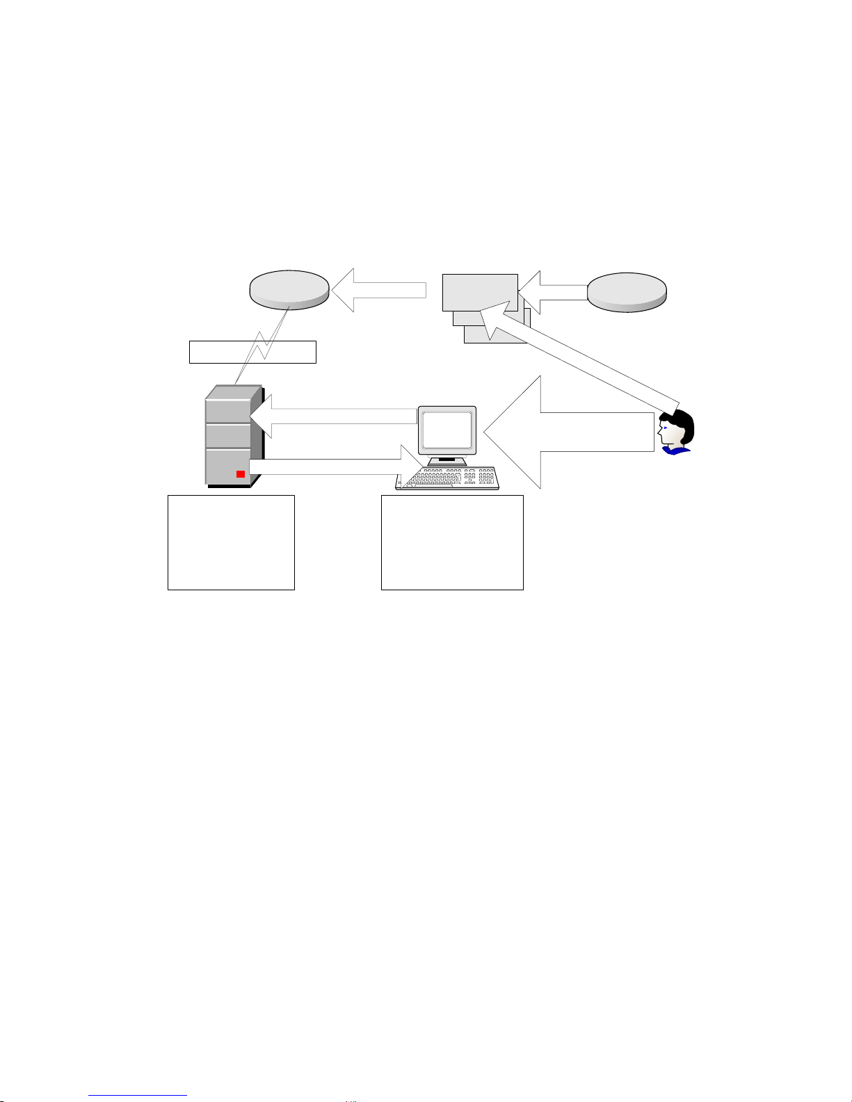
Group ID
Group ID is for discriminating and managing the information received by the WRS from the HVR-04
belonging to group. The group ID should be unique to avoid unauthorized access to the HVR-04.
Unauthorized users will not be able to access the HVR-04 unless they have a login name and password,
but they will be able to see the unit on their registration list.
Group ID and IP
ISP
Internet
IP
Grup ID and IP
WRS
DS412 registers its
Group ID and
Dynamic IP address
on WRS
eDVR Manager
eDVR Manager
accesses WRS and gets
DS412's IP addresses of
registered Group
Group ID
DS412s of selected Group
Administrator /
User
Register WRS address and
Group ID on eDVR Manager
DS412
A
s
s
i
g
n
G
r
o
u
p
I
D
Status
Displays the registration status of the HVR-04.
56
Page 57
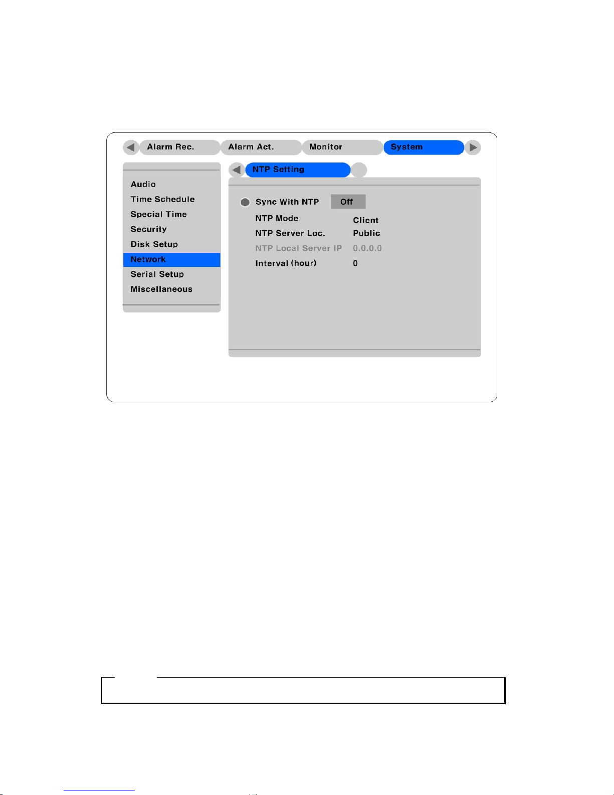
5.7.6.4. NTP setting
NPT is synchronized all of machine in network.
Sync With NTP
. On/Off NTP function
NTP Mode
Set up the NTP mode.(client or Both)
NTP Server Loc.
If you set up Client, NTP mode will be Enable. (Set up the NTP server to connect Local Network or
Internet)
NTP Local Server IP
At the time of a setup by Local , it will be set to enable NTP Server Loc
You have to input HVR’s IP or NTP server’s IP from Local Network.
Interval (min)
To set periodic time.
<Note>
When client is NTP Mode, you must be set up Sync with NTP “On”
57
Page 58
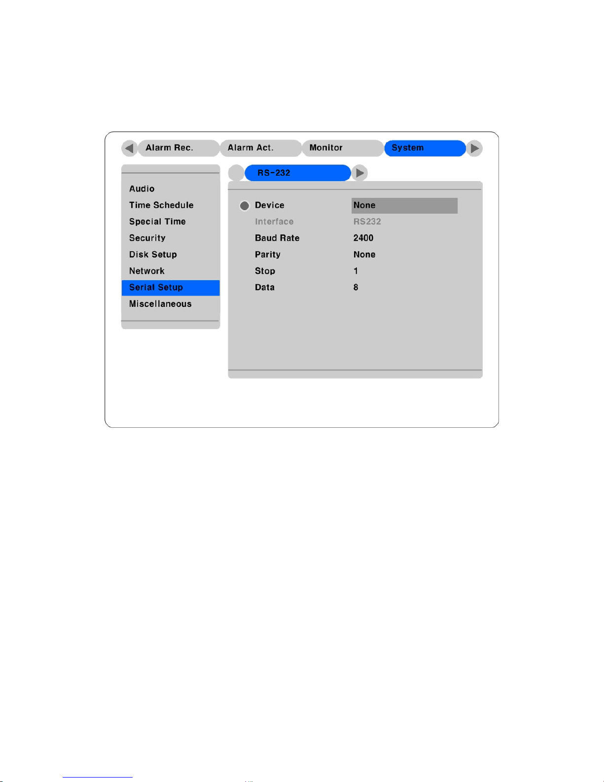
5.7.7. Serial setup
There are two RS232 menus (One for external devices connected via the DB-9 pin, and the other for PTZ
setting) and one RS 422/485 menu.
Device
Designate the connected external device.
Interface
Used to designate the protocol on the RS422/RS485 Menu.
Baud rate/Parity/Stop (bit)/Data (bit)
Each value should be set according to the specifications of the connected external device.
58
Page 59
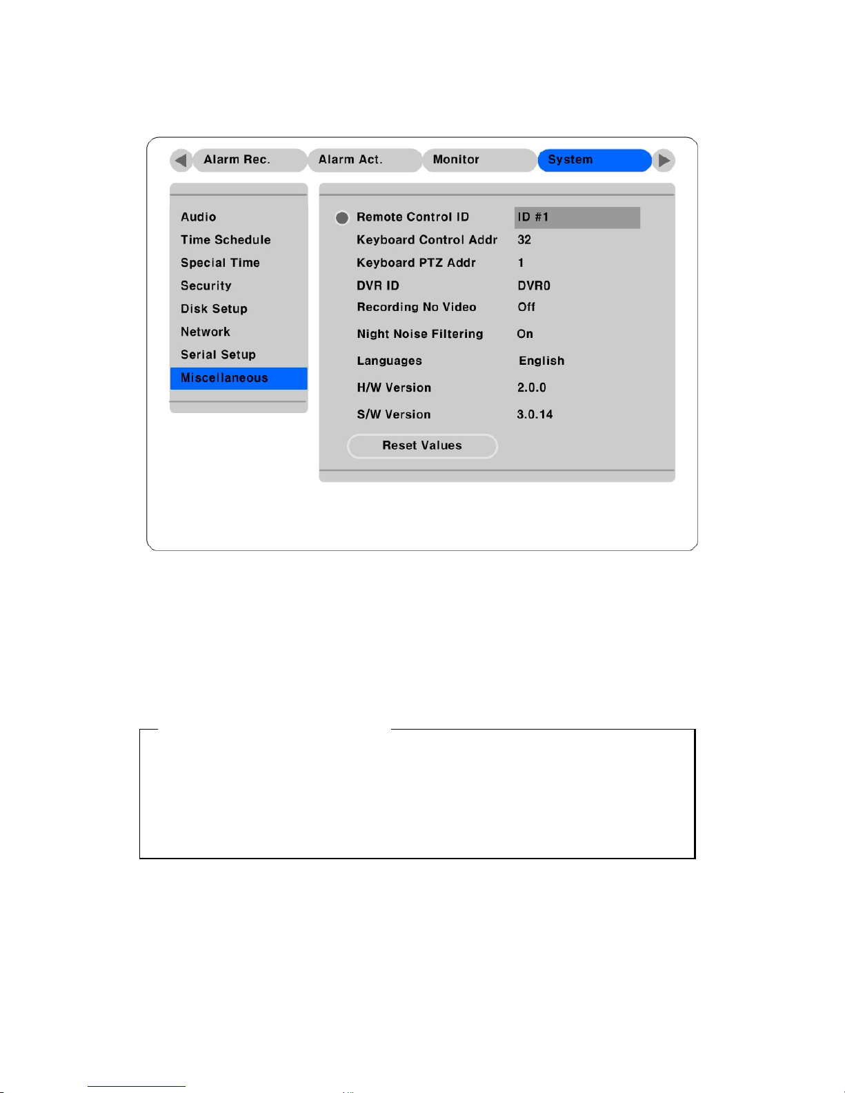
5.7.8. Miscellaneous
Button control
- Press [MENU] button and select “Miscellaneous” below the “System” tab.
Remote Control ID
Up to sixteen HVR-04s can be controlled with a single IR Remote Control. Designate each unit with a
unique number under the ‘Remote Control ID’ menu.
< How to register remote controller >
- Aim remote controller at the HVR-04.
- Press the “ID” button of remote controller until HVR-04 reacts.
- If remote controller’s ID agrees with HVR-04’s, all the LEDs on the front panel of the HVR-04 will
light up and a buzzer will sound.
- OSD menus can now be set with the remote controller.
59
Page 60

Keyboard Control Addr
To set keyboard’s control address in order to operate all HVR-04’s menus with keyboard. Default value is
“1”.
Keyboard PTZ Addr
To set keyboard’s PTZ address in order to operate each PTZ camera with keyboard. If setting just first
camera’s address of each HVR-04, another cameras’ are designated automatically. For example, 1
st
HVR-
04 has five cameras and 2
nd
HVR-04 has six cameras, keyboard PTA address of 1st HVR-04 should be set
as “1” and one of 2
nd
HVR-04 be set as “6”. Be cautious that PTZ addressed are assigned to all cameras
automatically in spite of non PTZ camera.
* Since Keyboard Control Addr and Keyboard PTZ Addr run differently according to the kind of
Keyboard, it is recommended to refer to each tech note for using keyboard.
DVR ID
For use with the DVR Manager to control and manage several HVR-04s.
IP Cam Menu
To enable the IP camera options for the “Camera,” “Recording,” and “Alarm Recording,” tabs.
Language
To select the language used for the OSD Menu.
Reset V alues
To reset current configured values. To reset DVR, press the “Reset Values” button.
60
Page 61
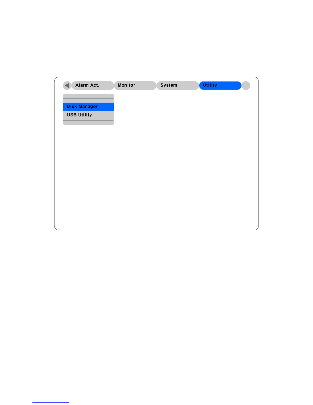
5.8. Utility
The following description is how to add/format internal or external HDD. HVR-04 supports various
external storages.
Button control
- Press [MENU] button and move to “Utility” below the “System” tab.
61
Page 62
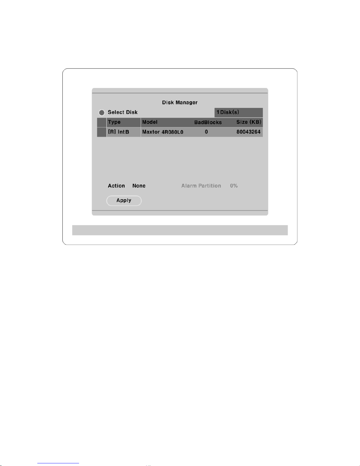
5.8.1. Disk manager
A connected HDD is detected automatically.
Select Disk
To select a Disk.
Action
Select from “Add/Format/Confirm Removed/Add used”.
: To add disk (you must be use empty disk in partition table.
[Add]
: To remove current HDD formatted for use.
[Remove]
[Confirm
Removed]
: Removed HDDs are still listed in the system and can be re-added (“Add
Used”) without losing data. “Confirm Removed” will permanently remove the
drive and all data will be lost.
[Add used]
: It is to add a HDD that has been previously used. The disk does not need to be
re-formatted.
<File system compatibility> Disk used at ver 1.x and 2.x of HVR can be reused without deleting its data.
Fat32 Format
When connected external device, you have to use Fat32 Format.
62
Page 63

Format the partition of below 250GB to copy/backup by FAT32 file system.
It is necessary to create partition by using Disk manager on PC for this work.
In case the size is over 250GB, format each partiton by FAT32 file system after
creating multiple partitons smaller than 250GB.
Type
There are several symbols to indicate HDD status.
[R]
: Available for recording
[V]
: Connected and formatted as HVR-04’s file system.
If using ‘Add used’ command, it will be changed to [R]. There is no need to format again.
[F]
: Connected but not available file system. After using ‘Add’, need to format to make HDD
available for recording [R].
[X]
: HDD cable is not connected or HDD has a problem. It is recommended to delete from list
using ‘Confirm Removed’.
[C]
: Available for backup to the external CD-Writer.
< File system compatibility >
Instructions
- When upgrading DVR is completed, HDD used at below version will have the sign of [V] at Disk
Manager.
- Select HDD at Select Disk.
- Select ‘Add Used’ at Action and press the button of ‘Apply’.
- Click OK at ‘NOTICE - Disk reused for recording’.
- Converting process will be going on after the message of ‘Converting files from old version may
take a few minutes’ appears.
- If the sign of Type changes into [R], the status of HDD is usable.
Warning
- HDD used at below version will have sign of [V] when upgrade is completed and re-use is possible
only with Add Used.
- ‘Add Used’ process may take from 10 seconds to a few minutes according to the capacity of HDD.
- Playback recorded data of HDD used at below version may have problem and CD backup is
impossible.
- The function such as Watermark or Smart Search can not be supported at recorded data of below
version.
- Please note that some functions and backup can not be supported as above explanation even if file
system is basically designed to be conpatible between each other, so data backup is recommended
before upgrading.
63
Page 64
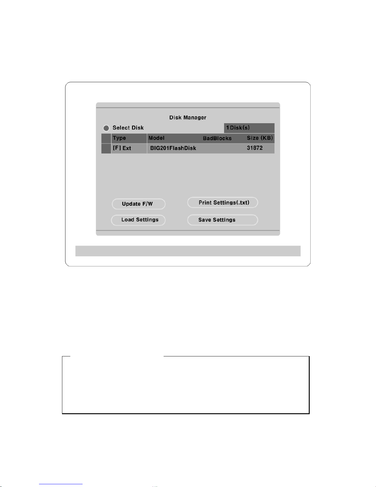
5.8.2. USB utility
It is possible to firmware upgrade, set up, saving, text file saving for printing throughout USB device
Update F/W
It is possible to update firmware by USB device. After connect USB device and then Press the “Update
F/W” button. File extension is “~date”
Print Settings(.txt)
It is possible to print by USB Text file. First you have to open saved file by editor and then print it.
<TEXT saving set up file Item>
- Camera setting information
- Recording setting information
- Alarm Recording setting information
- Network setting information
- Audio setting information
Load Settings
64
Page 65

Saved setting value saves to USB device
Save Settings
Currently setting value saves to USB device
65
Page 66
Advanced configuration
HVR-04 has the default settings of IP camera channels disabled. HVR-04 can support 12 IP channels and
4 analog cameras simultaneously. And current system can be expandable easily with connecting text or
keyboard device.
6. Using IP cam
6.1. Activating IP cam menu
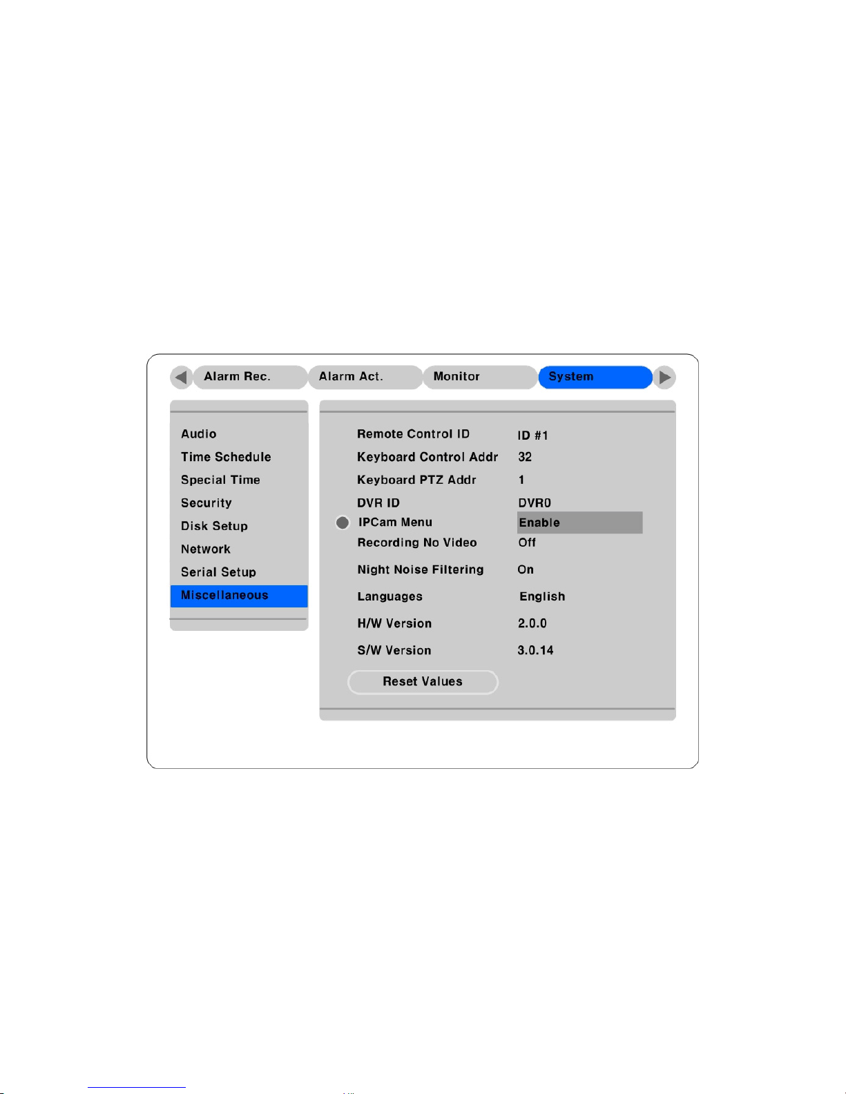
To setup the IP cam menu, first enable the IPCam Menu under the “System” tab.
Button control
- Move to “Miscellaneous” below “System” tab.
- Set “IP Cam Menu” to “Enable.” This will activate the IP cam menus for the Configuration Menu.
66
Page 67
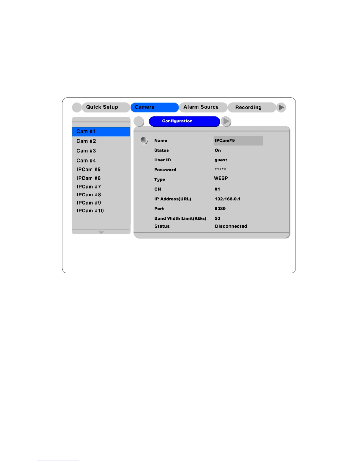
6.2. Camera setting – IP camera channels (Ch 5 ~ Ch 16)
Setting up the IP Cameras is similar to setting up the analog channels. However there are specific menus
only for IP cam; for example, the ‘Configuration’ menu and ‘Network’ menu in the IP cam setting menu.
6.2.1. Configuration
Button control
- Press [MENU] button and move to each “IPCam #5 to #16“ below “Camera” menu. Then select
“Configuration” menu by pressing the [ENTER] button and using the ◄◄ or ►► buttons.
Name
Press the [ENTER] button to open the related dialogue box and change the camera name.
Status
Press the [ENTER] button and use the ◄◄ or ►► buttons to set the camera to “On” or “Off.” Unlike
the analog channels, the IP cam’s default value is “Off.” After registering the IP camera, set the status to
“On.”
67
Page 68

User ID/Password
The related IP camera’s ID/Password should be entered. Default value is “guest/guest.” To change the
ID/Password, press [ENTER] to open the dialogue box (similar to the “Name” box.)
Type
Set “WESP/WebEye/I-Rec” by pressing the [ENTER] button and using the ◄◄ or ►► buttons.
CH
Designate the channel for the IP camera. For example, the WebEye B106 has 6 possible channels, the I-
Rec B104 has 4 possible channels, etc.
IP Addr ess(URL)
Press the [ENTER] button to open related dialogue box to manually enter an IP address. To register an IP
cam, there are two methods; manually enter the IP using the dialog box (similar to the box for “Name”) or
select an IP from the Local IP Cam List. To use the Local IP Cam List, please refer to the next page.
Port
Press the [ENTER] button to open the related dialogue box to manually enter the Port Address. The
default values are different according to IP camera type; “8080” is the “WebEye” default and “8001” is
the “i-Rec” default.
Band Width Limit(KB/s)
To control transfer speed with data size. Basically HVR-04 can also control it with ips control. It can be
set between 10KB and 100KB against the overload of network bandwidth. When setting 1ips at network
camera menu and 10KB at this menu, HVR-04 receives video data of 1ips within 10KB. If data size is
9KB, it will not be problem. But if it is 11KB, one image will not be able to be transmitted per second.
68
Page 69
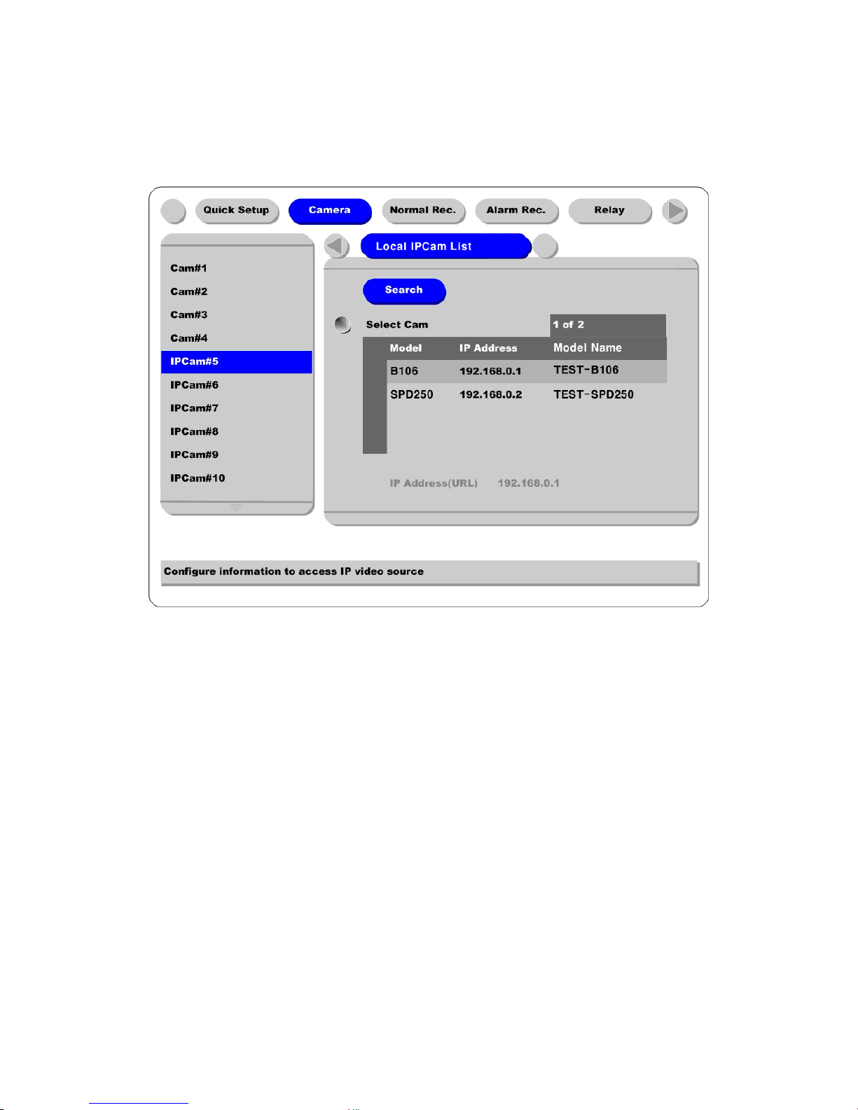
6.2.2. Local IP cam list
This menu is for easy registering of local IP cameras. If HVR-04 is connected to network and IP cameras
are connected to the same local network, they are listed in this menu.
Search
Select this button and press the [ENTER] button to refresh the list of local IP cameras.
Select Cam
Select “Select Cam” by pressing the [ENTER] button and select the desired IP camera from the list. When
using this method, the IP Address, Type, and Port are automatically configured on the previous screen.
69
Page 70
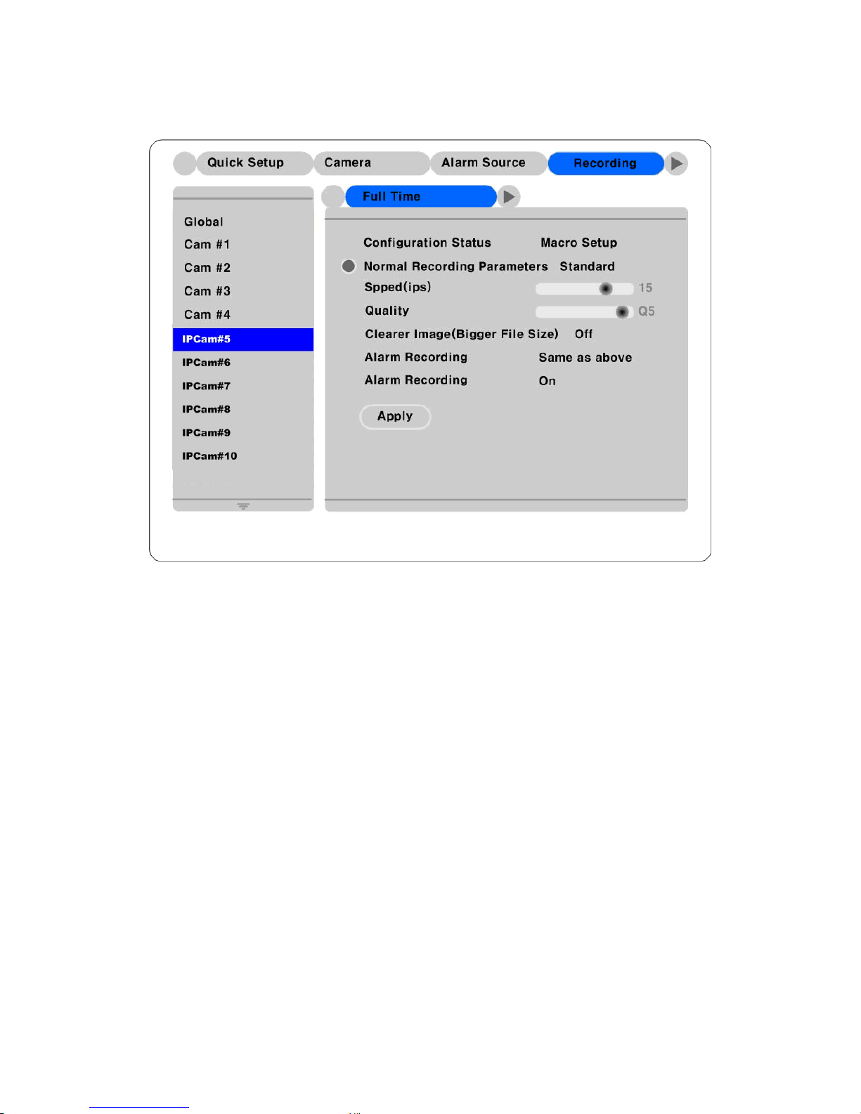
6.3. Recording – IP camera channels (Ch 5 ~ Ch 16)
These settings are same as with the analog channels.
70
Page 71
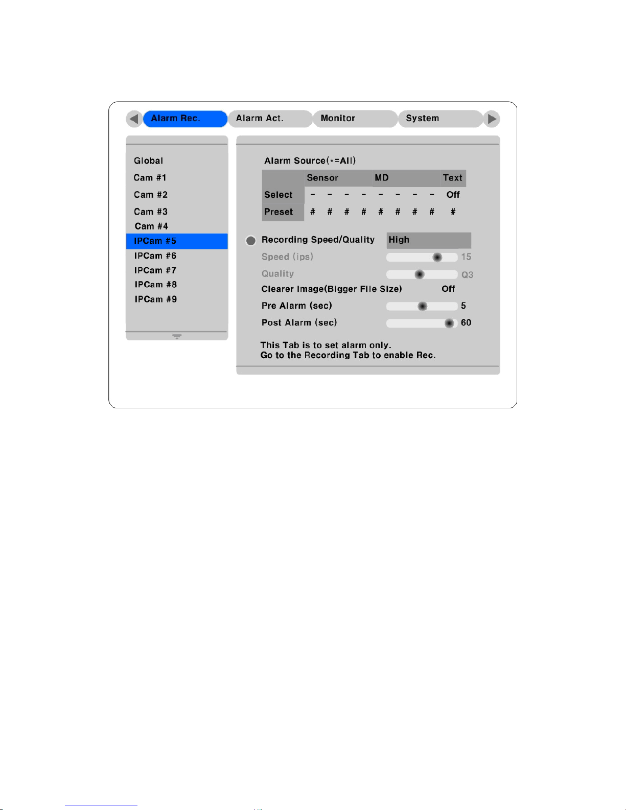
6.4. Alarm rec. - IP cam channel (Ch 5 ~ Ch 16)
These settings are same as with the analog channels.
71
Page 72

6.5. IPCam sensor
When using IPCam, you can use sensor like a DVR’s sensor. You could be add 12 sensor so totally you
can use 16 sensor.
IPCam # Sensor #
S5 5 1
S6 5 2
S7 # 3
S8 # 4
When setting up as mentioned above, IPCam‘s sensor 5,sensor 1, it is used like DVR’s Sensor 5.
This function only possible I-Rec or WESP
6.6. IPCam Relay
When using IPCam, you can use relay like a DVR’s relay. Possible to add 12 IP Camera so totally upto 16
IPCams.
IPCam Relay Configuration
Set up IPCam Relay R5 to R16. It is only support IPCam Type.
72
Page 73
7. Connecting external device
7.1. Using text device
In order to use text device, the following four menus should be set; Text menu, Serial Setup’s RS232
menu, Alarm Rec. menu, Rec. menu
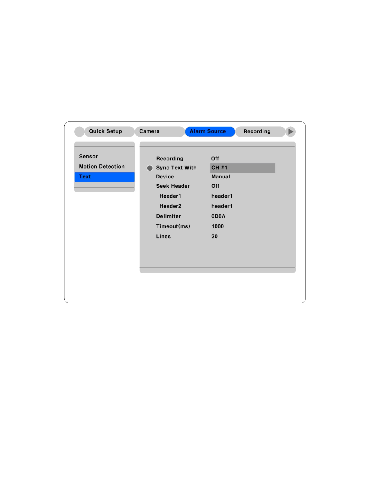
7.1.1. Setting at text menu
Set both Recording and Monitoring as “On”
Set “Sync. Text with” value.
If the connected device is Star Finger 007, select it at “Device” menu. If not, set ”Manual” and each sub-
menus.
73
Page 74
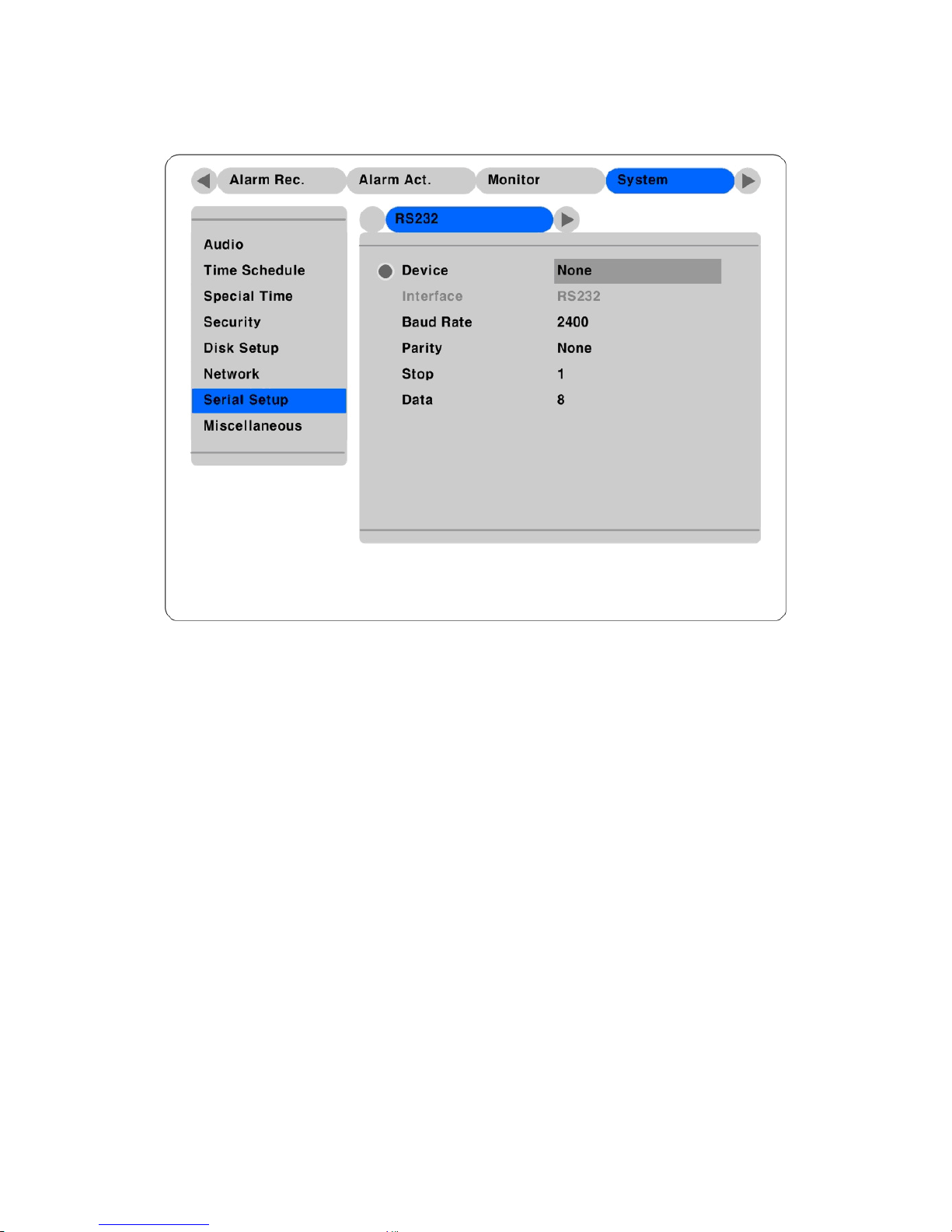
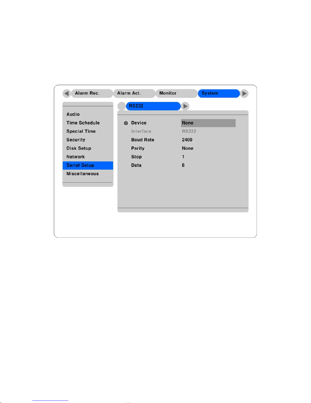
7.1.2. Setting at serial setup’s RS232 menu
Set RS232’s device menu as “Text”. And set baud rate, parity, stop, and data.
74
Page 75
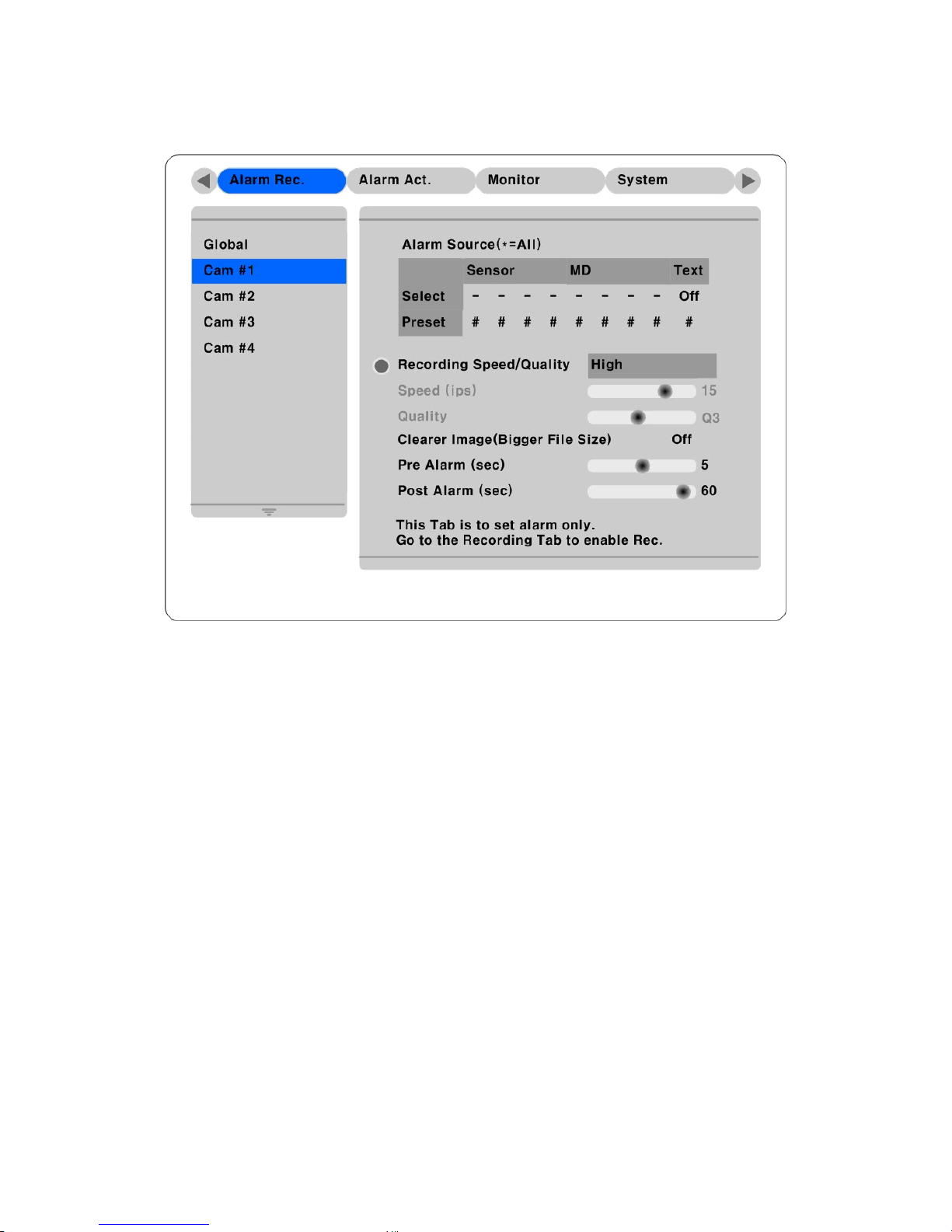
7.1.3. Setting at alarm rec. menu
If you want use text as a alarm source, set text event as “On”.
75
Page 76
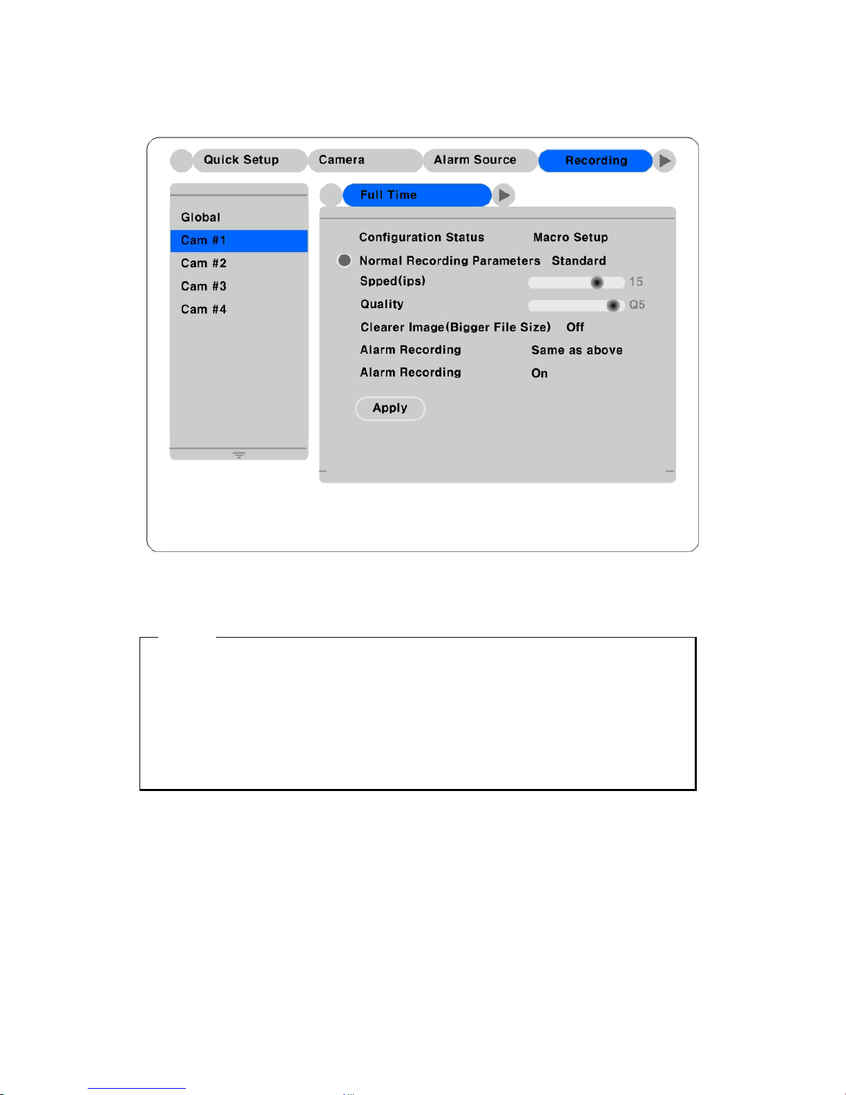
7.1.4. Setting at recording menu
Set event recording as “On” at each time schedule.
<Note>
Whenever pressing the “Help” button, information of displayed image is different.
The default value of Monitoring mode is to show just channel number. Then next step is to show
channel name and text, event status, and HDD status.
The default value of Playback mode is to show all information. The next level is to show channel name
and text, event status, and channel number.
So in order to view text data, press the “Help” button once at both Monitoring and Playback modes.
76
Page 77
7.2. Using keyboard
In order to use keyboard, the following two menus should be set; Serial Setup’s RS232 menu, Serial
Setup’s PTZ menu
7.2.1. Setting at serial setup’s RS232 menu
Set RS232’s device menu as “Keyboard”. And set baud rate, parity, stop, and data.
7.2.2. Setting at serial setup’s PTZ menu
Set PTZ camera to control with keyboard. For more detailed technical solution, please contact the closest
local HUNT ELECTRONIC’s distributor.
77
Page 78

APPENDIX
APPENDIX
78
Page 79

Appendix #1 Technical specification
Hardware
32bit RISC Embedded processor (200MIPS)
Flash memory: 8Mbyte
RAM: 32Mbyte
OS: Embedded Linux
Storage device
Int.: 2 HDD bays
Ext: 3 IEEE 1394 (FireWire) connection ports
Supports Disk Management tool for all disks
(Reboot is required when HDD changed)
Total manageable capacity: 4 TB
Image quality control
5 Levels (Q1-Q5)
Image compression
Compression algorithm: Differential Wavelet
Compression rate: 20:1 ~500:1
Average file size: 3 ~ 5KB (S tandard Quality)
Video channel
NTSC or PAL video format are supported
4Ch. analog video inputs via BNC connector
Recording performance
(on 360X243) analog Ch
Max. 60fps(NTSC) / 50fps(PAL) in total
Max 30 fps (NTSC) per channel if 2ch used
Max. 15fps (NTSC) per channel if 4ch used
Schedule recording
Daily: Day / night / Four-segment time frame
Weekly: Weekdays / Weekends
Status: Normal / Event
Matrix digital output schedule
Daily: Day / Night / Four-segment time frame
Weekly: Weekdays / Weekends
Conditions: MD, sensor input
Configurable recording conditions
Recording speed: None to 30 fps
Image quality: 5 Levels
Event conditions: MD & sensor inputs
Pre / Post alarm recording
Pre alarm recording: 1 ~ 10 seconds
Post alarm recording: 1 ~ 60 seconds
79
Page 80

Intelligent file system
Data-loss protection against power failure
Event triggered video data storage
Overwrite prevention of event triggered data
Event log recording
Log archiving on HDD
Log search & monitoring via Network
Data(video & audio Clip) Back-up
Data Copy(Max. 1 minute’s video clip)
External HDD: IEEE1394 (FireWire) or USB
PnP memory stick: USB port
VHS video tape: Video output port for VCR
Backup notification: Daily / Weekly / Monthly
PnP USB storage(Compact flash, Smart media,
Memory stick, SD card)
Displaying performance
Frame rate on CCTV Monitor: Max. 120fps
Frame rate on PC: Max. 60ips
Display channel: Quad, Auto sequential
Play speed: 1x, 2x, 4x, 8x, 16x (FDW & REV)
Supports step-forward, step-reverse.
Instant data access based on time and event log
Digital zoom
2 times digital zoom (Live & Playback Mode)
Event triggered pop-up video
Triggered by motion detection or sensor input
PTZ control
Ports: RS232, RS485/RS422
Front panel push button & IR Remote
(controls IP video channels as well)
Local user
On-the-screen PTZ control on PC
Preset: 8 points per channel
Group: 1 group per channel
Remote user
Return Home Position’ support
Software-controlled 4 sensor inputs
Sensor inputs and alarm outputs
Software-controlled 4 alarms outputs
Audio recording and playback
Input: 1Ch, line-in, 1Vpp
Output: 1Ch, line-out, 1Vpp
Level: -7 ~ 8 Recording level control
Support 20dB Amp. for low level audio re cording
Supports local and remote audio monitoring
80
Page 81

Network
Protocol: TCP/IP, ARP, ICMP, DHCP, PPPoE
Line: 10/100Mbps Ethernet (RJ-45)
Simul. user support via network
Monitoring: Max. 5 users
Playback: Max. 5 users
Firmware upgrades via Network
Management and Firmware upgrades
Password (User or Administrator Authentication)
Security
Watermarking (For image copyin g)
Input: AC 100~240V, 50~60 Hz
Power supply (included)
Output: DC 12V, 5A
Booting: Max. DC 12V ± 10%, 4.5A (54W)
Power consumption(with 2HDD)
Normal: DC 12V ± 10%, 3.9A (35W)
Operating: 41 ~ 113 degrees F.
Environmental spec
Storage: -49 ~ 149 degree s F.
81
Page 82

Appendix #2 Utilizing IP addresses on local network
#2.1 Introduction
Most of our businesses are done via Internet, lately. We play with information by transmitting through e-
mails and searching the world of Internet. IP address is what we utilize to access to the Internet.
Currently used IP addresses are limited. And there are 5 classes’ networks in the world for now, and a
network contains lots of IP addresses. A network can hold limited IP addresses. The numbers depend on
network class. 5 classes are from A to E, and the most common one is C class network.
#2.2 IP construction and network class
1) IP construction
( (xxx: 0 – 255)
e.g. 192.168.1.1
xxx xxx xxx xxx
X1 X2 X3 X4
2) Network class
A class: A network that contains IP addresses from 0 to 127 at room ‘X1’.
- Network ID: X1
- Host ID: X2, X3, X4
- Total number of A-class networks is 128 in the world.
B class: A network that contains IP addresses from 127 to 191 at room ‘X1’.
- Network ID: X1, X2
- Host ID: X3, X4
- Total number of B-class networks is 65,534 in the world.
C class: A network that contains IP addresses from 192 to 223 at room ‘X1’.
- Network ID: X1, X2, X3
- Host ID: X4
- It is the most common network in the world, and the total number of C-class networks is 2,097,152
D class: A network that contains IP addresses from 224 to 239 at room ‘X1’. D-class network is for
multicasting, and it is not allowed to use for common users.
E class: A network that contains IP addresses from 240 to 225 at room ‘X1’. E-class network is reserved.
82
Page 83

#2.3 C-class network
1) Features of Addresses
IP address: Three digits number in room ‘X4’ are for Host ID, and the numbers are from 0 to 255.
Among the numbers, 0 is used for Network ID, 1 is used for Router IP (Gateway address) and 255 is used
for Broadcast address. Therefore the numbers from 2 to 244 are IP addresses that can be assigned to
WebEye, i-Rec B104, PC etc.
Network ID: It is to identify a network. Generally the first number is assigned as Network ID.
Gateway address: It is an IP address of router that is connecting Internet and local network. Remote
users can access local network over Internet through the gateway (router). Generally the second number is
assigned as Gateway address.
Broadcast address: It is to broadcast to all devices that are connected on local network. Broadcast
address is a destination for broadcasting and it is determined by calculating. All devices connected on
local network have a same Broadcast address.
Subnet Mask: It is to divide a local network into two remote networks. Subnet mask shows the IP
quantity in a certain network. The numbers that can be used as subnet mask are limited (0, 4, 8, 16, 32, 64,
128)
2) Network configuration
(1) To use as one network
Network ID: xxx.xxx.xxx.0
Gateway Address: xxx.xxx.xxx.1
Subnet Mask: 255.255.255.0
Broadcast Address: xxx.xxx.xxx.255
IP Addresses: xxx.xxx.xxx.2 – xxx.xxx.xxx.254
83
Page 84

(2) To use as two sub-networks (1/2 + 1/2)
Sub-Network ID: xxx.xxx.xxx.0
Gateway Address: xxx.xxx.xxx.1
Subnet Mask: 255.255.255.128
Broadcast Address: xxx.xxx.xxx.127
IP Addresses: xxx.xxx.xxx.2 – xxx.xxx.xxx.126
Sub-Network ID: xxx.xxx.xxx.128
Gateway Address: xxx.xxx.xxx.129
Subnet Mask: 255.255.255.128
Broadcast Address: xxx.xxx.xxx.255
IP Addresses: xxx.xxx.xxx.130 – xxx.xxx.xxx.254
(3) To use as three sub-networks (1/4 + 1/4 + 1/2)
Sub-Network ID: xxx.xxx.xxx.0
Gateway Address: xxx.xxx.xxx.1
Subnet Mask: 255.255.255.192
Broadcast Address: xxx.xxx.xxx.63
IP Addresses: xxx.xxx.xxx.2 – xxx.xxx.xxx.62
Sub-Network ID: xxx.xxx.xxx.64
Gateway Address: xxx.xxx.xxx.65
Subnet Mask: 255.255.255.192
Broadcast Address: xxx.xxx.xxx.127
IP Addresses: xxx.xxx.xxx.66 – xxx.xxx.xxx.126
Sub-Network ID: xxx.xxx.xxx.128
Gateway Address: xxx.xxx.xxx.129
Subnet Mask: 255.255.255.128
Broadcast Address: xxx.xxx.xxx.255
IP Addresses: xxx.xxx.xxx.130 – xxx.xxx.xxx.254
84
Page 85

(4) To use as four sub-networks (1/4 + 1/4 + 1/4 + 1/4)
Sub-Network ID: xxx.xxx.xxx.0
Gateway Address: xxx.xxx.xxx.1
Subnet Mask: 255.255.255.192
Broadcast Address: xxx.xxx.xxx.63
IP Addresses: xxx.xxx.xxx.2 – xxx.xxx.xxx.62
Sub-Network ID: xxx.xxx.xxx.64
Gateway Address: xxx.xxx.xxx.65
Subnet Mask: 255.255.255.192
Broadcast Address: xxx.xxx.xxx.127
IP Addresses: xxx.xxx.xxx.66 – xxx.xxx.xxx.126
Sub-Network ID: xxx.xxx.xxx.128
Gateway Address: xxx.xxx.xxx.129
Subnet Mask: 255.255.255.192
Broadcast Address: xxx.xxx.xxx.191
IP Addresses: xxx.xxx.xxx.130 – xxx.xxx.xxx.190
Sub-Network ID: xxx.xxx.xxx.192
Gateway Address: xxx.xxx.xxx.193
Subnet Mask: 255.255.255.192
Broadcast Address: xxx.xxx.xxx.255
IP Addresses: xxx.xxx.xxx.194 – xxx.xxx.xxx.254
85
Page 86

Hunt Electronic USA
978 W. 10th Street
Azusa, CA 91702
Tel : (626) 812-8868
Fax : (626) 812-8828
www.huntcctv.com
 Loading...