


H-200
H200 User’s Manual
August 27, 2003
HuneTec Co.,Ltd

Contents
General Information ………………………………………………..........4
Introduction ………………………………………………………………….....4
RF Specification ……………………………………………….. …………........4
Physical specification ………………….. …………………………………. …....4
H200 PC Link ……………………….. ………....……………………………...6
Manufacturer …………………………………………………………. ……......6
Technical Theory …………………………………………………….......7
Controller Circuit Descriptions ………………. ……………………..................7
Transceiver Circuit Descriptions ………..……. …………………………. …....11
User’s Manual ………………………………………………………... …16
Before You Start ………………………………………………………. ……19
Getting Started …………………………………...……………………. … ...29
Read Message ……………………………………………...……………. ……31
Write Message ……………………………………………………………. …..41
Contact ………………………………………………. ……………………..45
Scheduler ……………………………………………………………………...50
Task ……………………………………………………………………….. ….54
Memo …………………………………………………………………………56
Preference ………………………………………………………………. … .58
Alarm ……………………………………………………………………. ……66
Calculator ………………………………………………………………. … . …68
Lock ……………………………………………………………………..…….69
World Clock ……………………………………………………………… . …70
Game ……………………………………………………………. ……………71
Tx Set ………………………………………………………………. ………...73
Alert ………………………………………………………………. ………….74
My Mail ……………………………………………………………. ………...75
H-200 PC Link Program …………………………………………. …………..76
Device and Battery Care …………………………………………. …………..82
Troubleshooting ……………………………………………………. ………...83
Safety Information ………………………………………………….. ………...85

Part List ………………………………………………………………....86
Logic & RF Board Part List ………………………………………………......86
Keypad Board Part List …………………………………………………….....90
Block Diagram ……………………………………………………….....91
Controller Functional Block Diagram ……………………………………......92
Transceiver Functional Block Diagram …………………………………. …...93
Schematic Diagram ………………………………………………….....94
Controller Schematic Diagram.... ………………………………………...…...95
Transceiver Schematic Diagram . …... …………………………………….......96
Keypad Schematic Diagram ……………………………………………….....97

General Information
Introduction
# Small Size and Light Weight for Portability
# ReFLEX Two-way Messaging & E-Mailing
# Graphic User Interface for Easy Use
# Personal Information Management Support
# PC Connectivity for Data Back-up and Restoring with Desktop PC
RF Specification
- Receiver
Frequency Bands: 929 MHz - 932 MHz , 935 MHz - 942 MHz
Channel Spacing: 6.25 kHz , 10 kHz and 12.5 kHz
Bit Rate: 1600/2 level FSK , 3200/2 level FSK , 3200/4 level FSK , 6400/4 level FSK
Frequency Deviation: +/- 800 Hz and +/- 2400 Hz
Signaling: 2/4 level FSK
- Transmitter
Frequency Range: 896-902 MHz
Bit Rate: 800, 1600, 6400 and 9600 bps
Channel Spacing: 12.5 KHz in 6.25 KHz steps
Frequency Deviation: +/- 800 Hz and +/- 2400 Hz
Signaling: 4 level FSK

Physical Specification
# Operating temperature range: -10°C ~ +50°C (32F~122F)
# Dimensions
-Size: 105×70×18mm
-Weight: 120g
# Power Consumption
-Batteries: Li-Ion 700mA rechargeable battery
-Stand-by Time: 7 days
-Recharging Time: 2 hours
-Rx Consummation: 45mA
-Tx Consummation: 800mA
-Idle Current: 1.2mA
# Display
-Full-graphics high-contrast screen
-Resolution 160×128 dots
-Lines by 24 characters
-Electro-Luminescent back lighting
-4 gray LCD
-Multi Font (Large / Small) Display

# Keypad
-32 QWERTY Keyboard
-slide keys
-4 navigation keys
# Accessories
-Mains charger
-Belt clip
-H200 PC Link software & editor cable
H200 PC Link
# Edit and back up address book memory
# Send and receive messages by using a PC keyboard
# Compose and change Bell melodies with H200 PC Link Maestro Manage settings
Manufacturers
Hunetec Co.,LTD
10th Hung-Kook Bldg.,Soonae-dong, Bundang-ku,
Sungnam-si, Kyungki-do, Korea 463-020
Telephone : +82-31-712-6868
Facsimile : +82-31-712-6889


Technical Theory
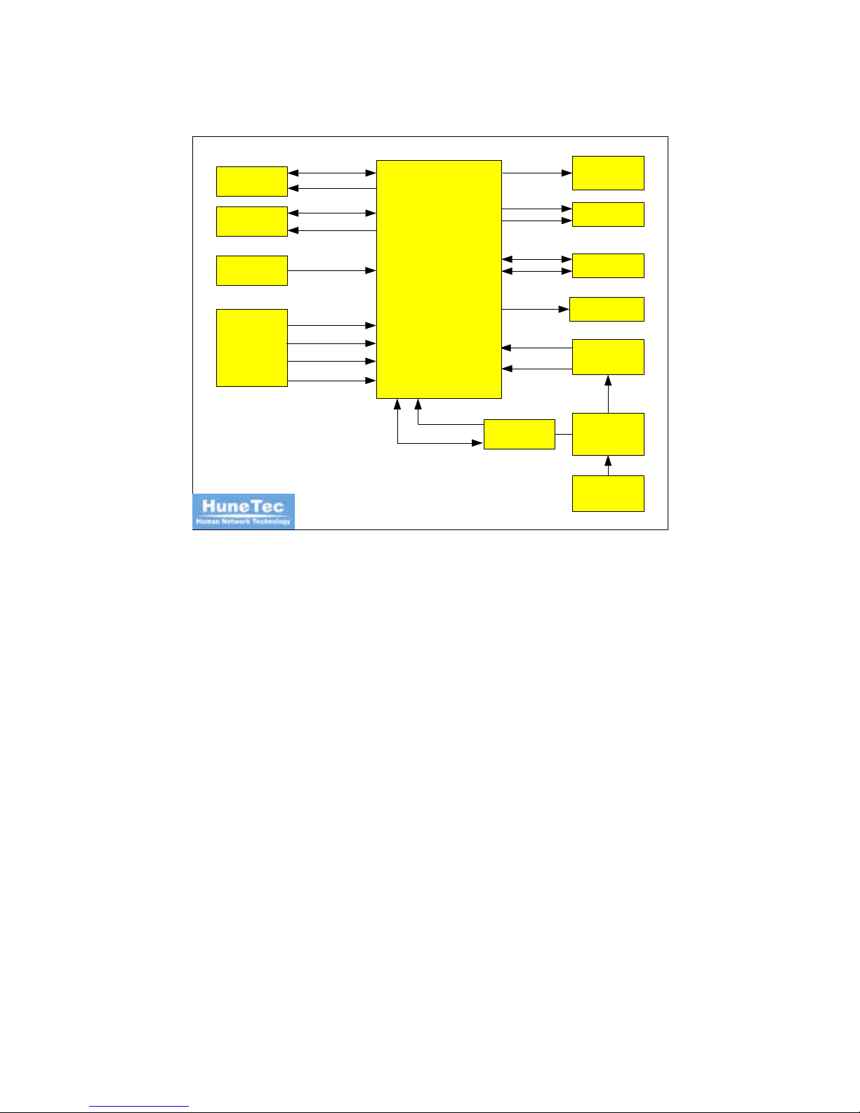
Controller Circuit Descriptions
The controller section consists of the following main functional blocks(see Figure 2-1)
# Functional Controller (U25)
# Message Storage (U24)
# Primary Code Storage (U23)
# Power Management (U304)
# Display Module
# Backlighting (U3)
# Serial Interface (U28)
# Audio (U31)
ADDRESS/DATA
ROM_CE
EXT_DET_SENSE
KEYIN[1:6]
SOUND1
VIB_EN
#RESET
FLASH
SRAM
KEYPAD
VIBRATOR
INTERFACE
CONNECTOR
POWER &
RESET
DISPLAY /
KEYPAD
BACKLIGHT
TRANSDUCER
ADDRESS/DATA
RAM_CE
LCD_CE
SOUND2
KSCAN[1:7]
CONTROLLER
+3.0V_L
RECHARGEAB
LE Li-Ion
BATTERY
POWER
MANAGEMENT
CIRCUITRY
DETECTOR
RSSI
DECODER
DATA IN / OUT
CPU_IRQ
SCK
READY/
SLAVE/
Figure 2-1. Controller Functional Block Diagram
1. Functional Controller
The functional controller (U25) provides user interface of the unit. The functional
controller affects the following components:
# Display Module
# Message storage (U24)
# Primary Code Storage (U23)
# Decoder (U26)
# Alert generators (vibrator at U17; transducer at U30)
# Display (U7) and Keypad Backlight
# Serial communication (U28)
# Primary code storage (U23)

2. Digital Signal Processor
The digital signal processor (U14) is responsible for the decoding
received information.
3. Message Storage
The message storage IC (U24) is a 4M bit SRAM (Static Random Access Memory)
contained in a 44-pin package
4. Primary Code Storage
The primary code storage IC (U23) is a 16-megabit flash memory IC contained in a 48-
pin package.
5. Power Management
After Battery voltage is authorized, voltage is authorized to internal LDO Regulator
(U13, U18, U410, U411, U412) and Reset generator through V
IN
of Power & reset IC
(U304). CPU is initialized through Reset signal which is input to CPU as Reset IN.
Output power V
out
(+3V) for Power & reset IC is used for Logic such as Digital Part of
Audio IC and CPU. Output power V
out
(+3V) for External Regulator is used for Analog
part of Audio IC and VCTCXO, PLL of Transceiver. Regulator is used for
authorization for regular voltage of EL through Battery voltage.

6. Display Module
The display driver is a flex circuit that drives Lines by 24 characters display. This
circuit attaches to the controller at contacts display module. The functional controller
(U25) provides sole control over the driver.
The display driver has an internal voltage triple that generates the appropriate voltage
levels needed to drive the display glass.
7. Backlight
The backlight consists of the following elements:
# Electro-Luminescent (EL) panels
# An EL driver (U3)
# EL contacts
When active, the EL panel draws approximately 90 volts peak-to-peak (200Hz) from
the driver.
8. Serial Port Interface
The serial port interface provides a connection between the HRD-100 communicator
and programming fixture.
9. AUDIO
Audio IC (U31) is a mono bridged audio power amplifier with DC voltage volume
control.
Circuit Descriptions
Specifications
1. Receiver
Item Specification
Frequency 929~932MHz, 935~942MHz
Channel Spacing 6.25 kHz , 10 kHz and 12.5 kHz
Bit Rate
1600/2 level FSK , 3200/2 level FSK ,
3200/4 level FSK , 6400/4 level FSK
Signaling Modulation 2 / 4 Level FSK
Frequency Deviation +/- 800 Hz and +/- 2400 Hz
Receiver Sensitivity 20uV/M with 80 char(TBD)
Frequency Accuracy 1ppm
Adjacent Channel Rejection
> 50dB from Sensitivity to -80dBm
> 40dB at -70dB Signal Level
> 30dB at -60dB Signal Level
Co-Channel Rejection
< 15dB at -105dBm
< 10dB at -102dBm
< 6dB at -95dBm
Spurious Response Rejection > 55dB at -105dBm
Image Rejection > 55dB at -105dBm
Inter-Modulation Distortion Rejection
> 50dB from Sensitivity to -80dBm
> 40dB at -70dB Signal Level
> 30dB at -60dB Signal Level
Simulcast Delay Spread Tolerance
> 1/4 symbol width at -105dBm and 15dB C/I
> 1/4 Symbol width at -102dBm and 10dB C/I
> 1/4 Symbol width at -55dBm and 6dB C/I
2. Transmitter
Item Specification
Frequency Range 896~902MHz
Channel Spacing 12.5 KHz in 6.25 KHz steps
Bit Rate 800, 1600, 6400 and 9600 bps
Signaling Modulation 4Level FSK
Frequency Deviation +/- 800 Hz and +/- 2400 Hz
Frequency Accuracy -2.5ppm < X < 2.5ppm
Frequency Stability -1.0ppm < X < 1.0ppm
Output Power 0.4W
Spurious Emission In-Band/Out-Band < -50dB
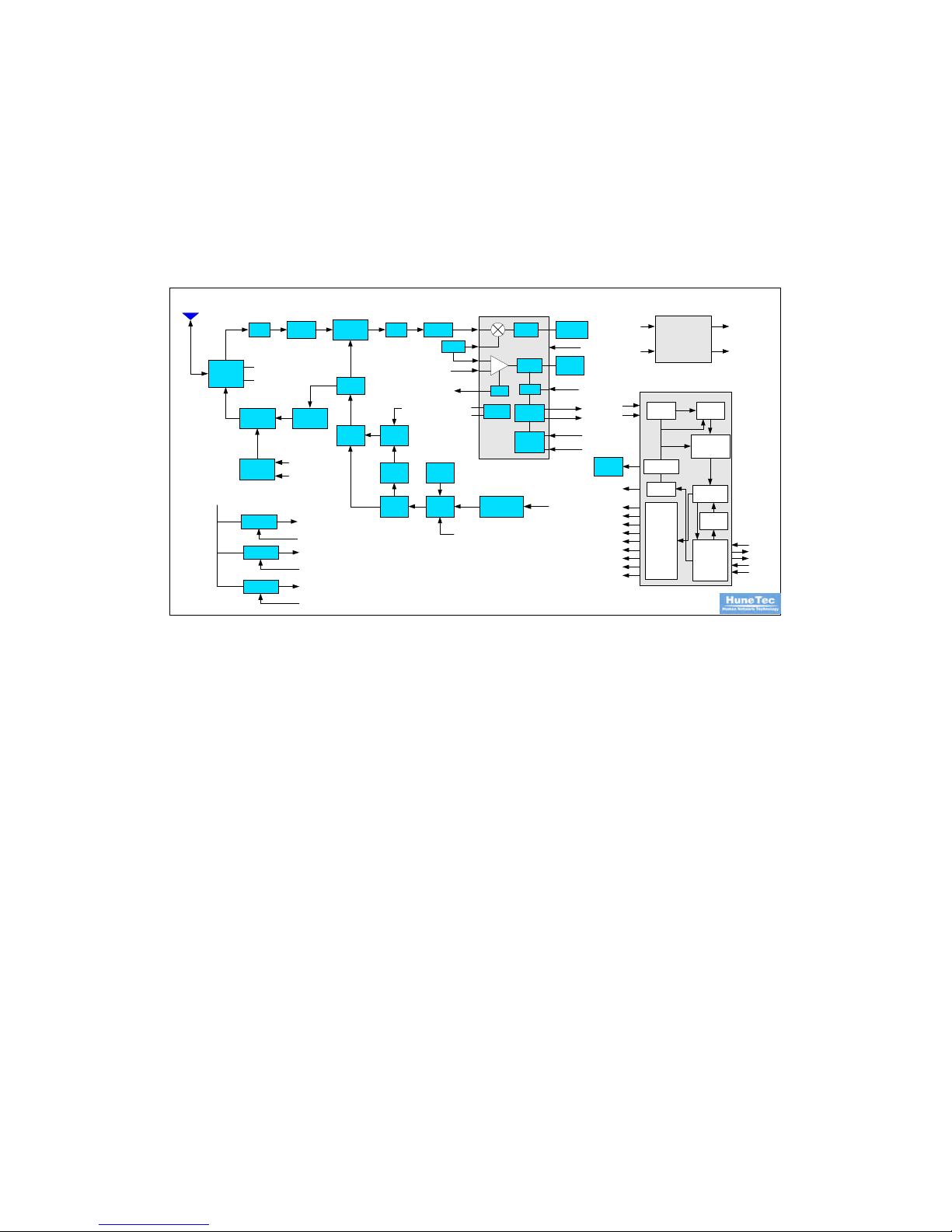
Circuit Descriptions
The following information describes the circuitry specific to HRD-100 pagers with
900MHz transceivers. See Figure 3-1.
20.945MHzLNA
ANTENNA
SWITCH
RX SAW
FILTER
DOWN
CONVERTER
MIXER
MCF IF AMP
TX DRIVE
AMP
POWER AMP
VCO PLL
FC=930.5MHz,
938.5MHz
RX CONTROL
TX CONTROL
PA
CONT.
VCTCXO
TX MOD.
FILTER
ADJUST
CIRCUIT
TX DATA
GAIN
CONT.
VCO MOD.
16.8MHz
LPF
BAT.(3.6V)
FC=21.4MHz
Regulator
Local
Oscillator
Comparator
RSSI
Quad
Detector
Filter
IF
AMP
Q/C1
CHARGE2
REG OUT
REG CONT
RSSI
DEC
MIX IN
BS
Tx_FIL_SEL
DETECTOR IC
SCLK
DOUT
DIN
SLAVE
READR_B
PLL_ON
Charge/
Discharge
Circuit
PA_ON
455KHz
IF IN
DISCRIMI
-NATOR
DA CONVERTER
4LEVEL
TX DATA
VCTCXO MOD
REGULATOR
BATTARY
(3.6V)
RX VCC (3.0V)
VCO VCC (3.0V)
TX VCC (3.0V)
RX_ON
TX_ON
DIGITAL
FILTER
TIMING
GENERATOR
DATA
BUFFER
BCH
ENCODING &
ERROR
CORRECTION
DATA
PROCESSIN
G
SERIAL TO
PARALLEL
CONVERTER
ADDRESS
BUFFER
RX/T
X
CONTROL
TX-DATA
PROCESS
TX1_ON
TX2_ON
BS
CHARGE1
CHARGE2
RX_FIL_SEL
TX_FIL_SEL
FSK1_ OUT
FSK 2_OUT
PLL_ON
TX DATA
PA_ON
76.8 KHz
ANTENNA
DECODER
PLL_ON
REGULATOR
REGULATOR
896M~902MHz
T
X
929M~932MHz
935M~942MHz
R
X
Rx_FIL_SEL
FSK2_IN
FSK1_ IN
FSK1_ IN
FSK2_IN
FSK1_ OUT
FSK 2_OUT
MICRO
CONTROLLER
Figure 3-1 Transceiver Functional Block Diagram
The transceiver board consists of the following major component sections:
# Antenna (ANT1)
# Antenna Switch (U102)
# Receiver Automatic Gain Control Circuit
# Low Noise Amplifier (U8)
# Receiver Surface Acoustic Wave Filter (U2)
# Receiver First Mixer (U104)
# Crystal Filter for First IF (MCF1)
# IF Detector IC (U12)

# Decoder (U26)
# Operational Amplifier (U9, U19)
# Transmit VCO/ Receiver First LO VCO (VCO1)
# Phase locked Loop
# Power Amplifier (U4)
# Driver Amplifier (U6)
1. Antenna
Antenna is for optimal receiving of transmission signal from base station.
Reduce damage of weak signal under general external environment and voltage from
device to a minimum.
2. Antenna Switch
The RF switch is it can be controlled with positive, negative or a combination of both
voltages. Some standard implementations include antenna changeover,
Transmit/Receive and diversity switching over 3W.
3. AGC (Automatic Gain Controller) Circuit
Level of signal which device receiving should maintain regular signal and AGC is for
Power control of device.
4. LNA (Low Noise Amplifier)
LNA is used for reducing noise to a maximum for optimal signal and amplify signal
that need to receive separately.
5. RF SAW (Surface Acoustic Wave) Filter
RF Saw Filter is used for band pass for the signal of receiving frequency and reduce
other signal except receiving frequency in order to receive selected receiving frequency
of Pager.

6. Down Converter (MIXER)
Down Converter is used for one output against two input signal and making IF signal
by combining amplified RF signal from LNA with Local signal.
Adjust RF signal of 930.5MHz ±1.5MH & 938.5MHz±3.5MHz and local signal of
909.1MHz & 917.1MHz to downward as the next IF signal of 45MHz.
7. Crystal Filter for First IF (MCF1)
The filter is centered 45MHz. The output of the first mixer has four frequency
components. The filter allows the passage of the desired IF frequency.
8. IF Detector IC (U12)
The IF Detector IC is a 4-level frequency-shift keying (FSK) comparator and a bit rate
filter switch.
9. Decoder (U26)
The decoder supports 1600, 3200, and 6400 bps decoding. Intermediate frequency
signals are demodulated, synchronized, de-interleaved and error corrected prior to entry
into a holding buffer. The holding buffer is then fed into a synchronous serial peripheral
interface (SPI) which then converts the data into a parallel format. A resident real-
time clock operates off a 76.8kHz crystal.
10. Operational Amplifier (U9, U19)
The Operational Amplifier is quad C-MOS operated on a single-power-supply, low
voltage and low operating current.
11. VCO(Voltage Controlled Oscillator)
VCO is used for creation of Local signal of ±1.5MHz.
12. VCTCXO(Voltage Controlled Temperature Compensated Crystal
Oscillator)

VCTCXO is used for voltage supply for reference frequency of main set input.
It creates 16.8MHz frequency and input to PLL IC.
It controlled by voltage for exact frequency tuning.
12. PLL(Phase locked Loop)
PLL(PLL2) is frequency combiner of Dual mode. It output IF signal and Local signal if
demultiplied signal and Phase of phase comparator is same.
13. Regulator
Regulator is used for authorization for regular voltage of VCO and RX circuit through
Battery voltage.
14. Driver Amplifier
Drive amplifier (U6) is circuit for promote efficiency through supply amplified signal
to power amp.
15. Power Amplifier
Power amplifier (U4) is amplifier circuit for the amplification of output signal in Drive
amplifier (U6) in order to transmit the signal to base station through Antenna.

User’s Manual
(Draft Version)

Contents
1. BEFORE YOU START………………………………………………………………………...……..19
1.1 DEVICE LAYOUT AND
ICONS ………………………………………………………………....20
1.2 KEYS DESCRIPTION…………………………………………………………………………....24
1.3 DISPLAY IN THE INITIAL
SCREEN…………………………………………………………..26
1.4 DISPLAY IN THE MAIN MENU
SCREEN……………………………………………………..27
1.5 LED INDICATOR………………………………………………………………………………...28
2.GETTING STARTED……………………………………………………………………………... ….29
2.1 HOW TO SWITCH DEVICE ON AND
OFF…………………………………………………....29
2.2 HOW TO CHARGE BATTERY…………………………………………………………………29
2.3 HOW TO RESET
DEVICE……………………………………………………………………….30
2.4 HOW TO TURN ON BACKLIGHT……………………………………………………………..30
2.5 HOW TO LOCK KEYBOARD ………………………………………………………………….30
3. READ MESSAGE…………………………………………………………………………………….31
3.1 INBOX
……………………………………………………………………………………………..32
3.2 INFO………………………………………………………………………………………………..35
3.3 DRAFT………………………………………………………………………………. …………….36
3.4 PERSONAL / BUSINESS /
MISC…………………………………………………. ……………..37
3.5 OUTBOX……………………………………………………………………………. …………….38
3.6 SENT…………………………………………………………………………………. …………....39
3.7
DELETE……………………………………………………………………………….. …………..39
4. WRITE MESSAGE………………………………………………………………………. …………..41
5. CONTACT………………………………………………………………………………. …………….45

6. SCHEDULER…………………………………………………………………………. ………………50
7. TASK…………………………………………………………………………………. ………………..54
8. MEMO ……………. …………………………………………………………………………………..56
9. PREFERENCE……………………………………………. ………………………………………….58
9.1 ALERT SETTINGS ……………………………………………. ……………………………………..58
9.2 QUICK TEXT ………………………………………………………………………………………..60
9.3 PRIVATE TIME ……………………………………………………………………………………...60
9.4 SETUP ……………………………………………………………………………………………….61
9.4.1 SET DATE & TIME ……………………………………………………………………………..61
9.4.2 DISPLAY SETTINGS …………………………………………………………………………....62
9.4.3 OWNER INFORMATION………………………………………………………………………..62
9.4.4 SIGNATURE………………………………………………………………………………....63
9.4.5 TITLE SCREEN …………………………………………………………………………………63
9.4.6 KEY LOCK PASSWORD………………………………………………………………………...63
9.10 ABOUT ……………………………………………………………………………………………..64
9.10 MYMAIL .SETUP ………... ………………………………………………………...........................65
10. ALARM ………………………………………………………………………………………………66
11. CALCULATOR…………………………. …………………………………………………………..68
12. LOCK…………………………………………………………………………………………………69
13. WORLD CLOCK……………………………………………………………………………………70
14. GAME………………………………………………………………………………………………...71
15. TX SET……………………………………………………………………………………………….73
16. ALERT……………………………………………………………………………………………….74
17. MYMAIL……………………………………………………………………………………………..75
18. H200 PC LINK PROGRAM ……………………………………………………………………… .76
19. DEVICE AND BATTERY CARE………………………………………………………………….82
20. TROUBLE SHOOTING…………………………………………………………………………….83
121. SAFETY INFORMATION ………………………………………………………………………...85

1. Before You Start
* What’s in the Box?
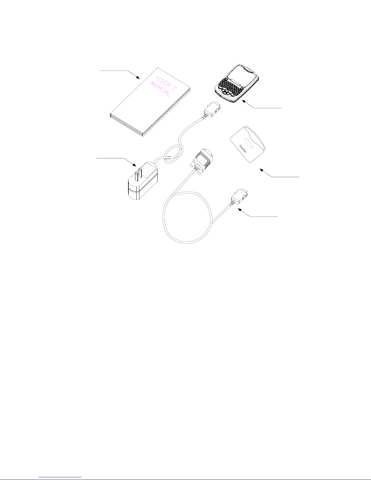
Product Literature
CODEX
Data Cable
(Optional Items)
Travel Charger
Holster
H 200
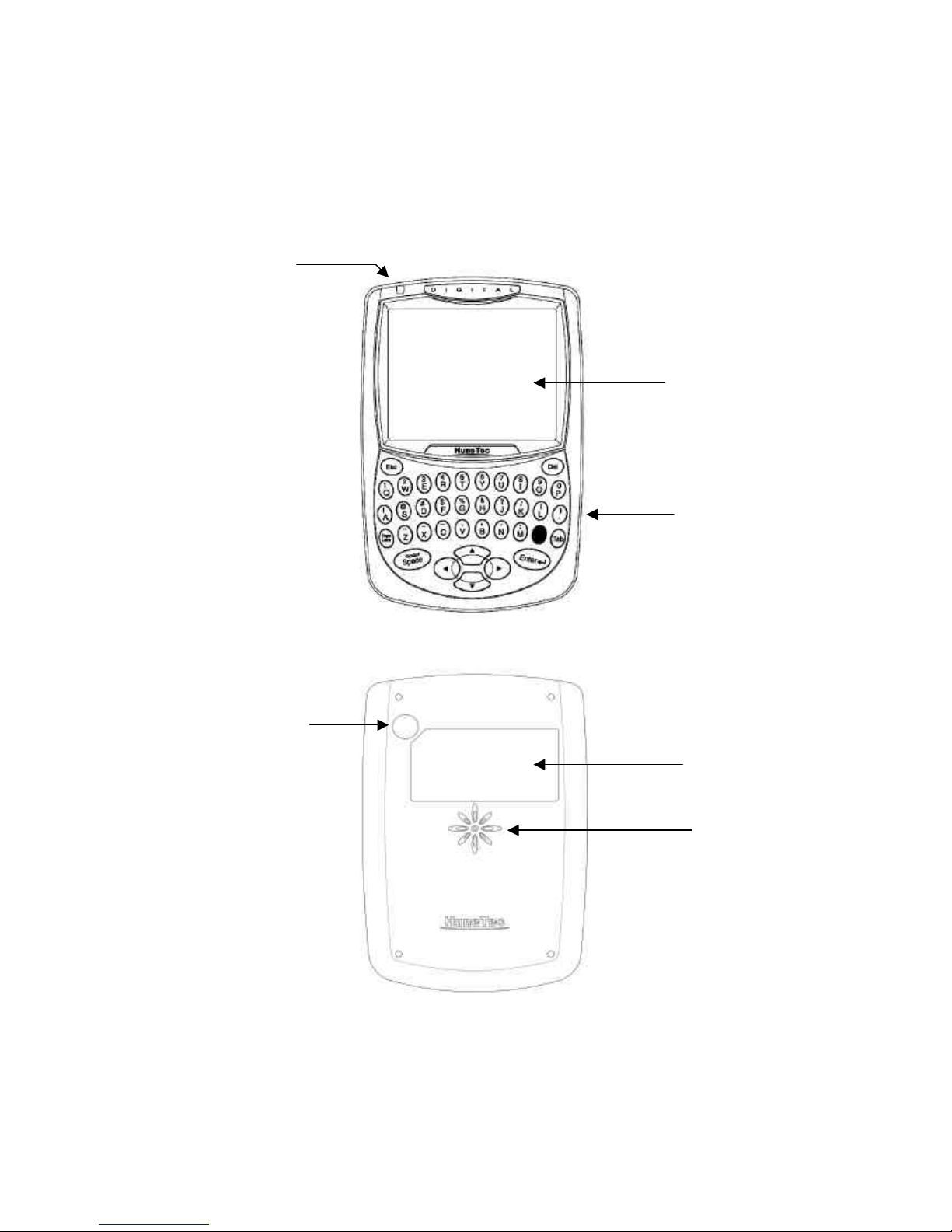
1.1 Device Layout and Icons
The following illustration shows the main elements of your H200.
< Front >
< Back >
Display
Keys
LED Indicator
Label
Speaker Hole
RF Test hole for AS only
(Do not uncover Rubber cap)
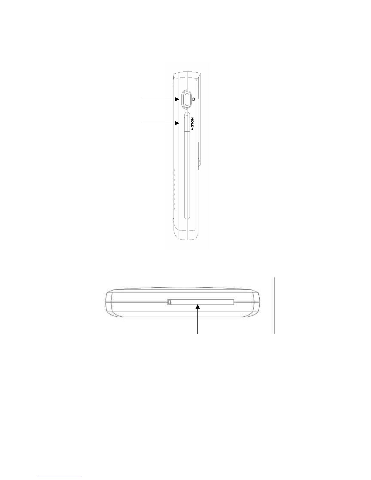
< Left Side >
< Bottom >
Power Button
Hold Button
Rubber cap for serial port and Reset switch
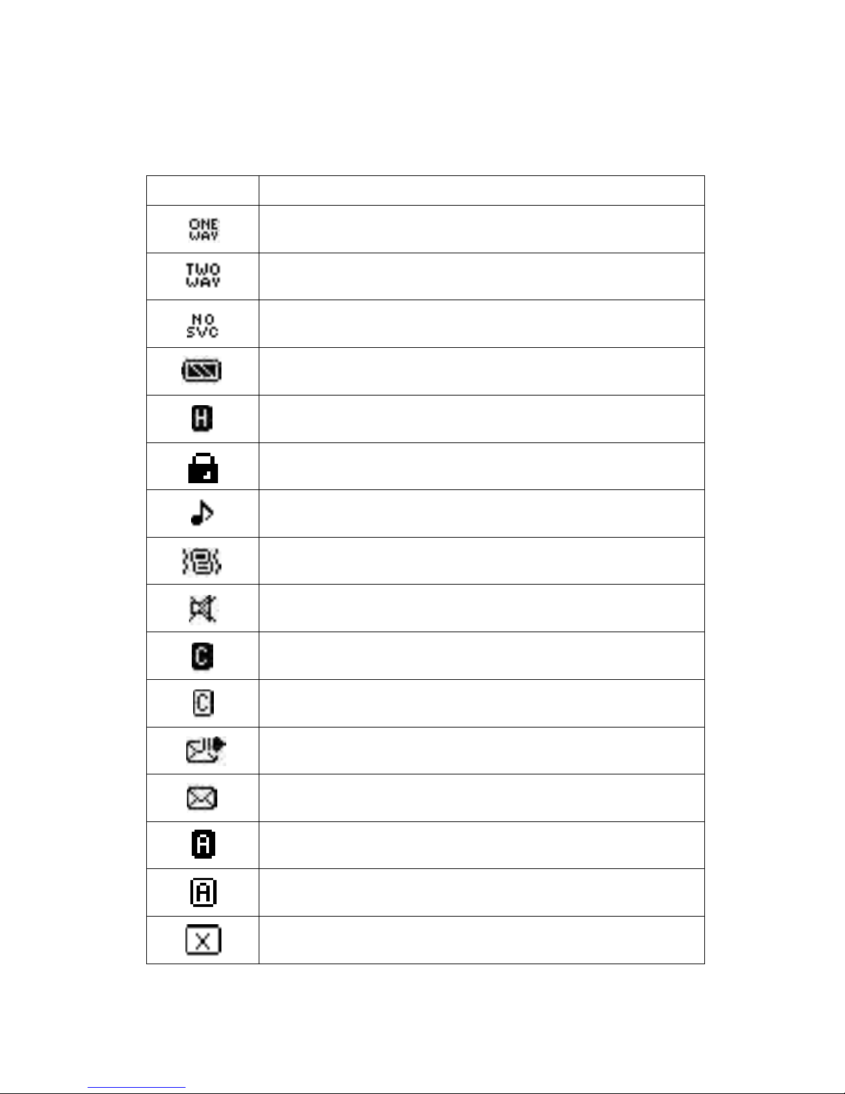
< Status Icons in the Main menu display>
Icon Description
Appears device is 1 WAY mode.
You can receive message only
Appears device is 2 WAY mode.
You can send and receive message
Appears device is No Service mode.
You are out of service range
Shows the level of battery status. The more bars you see, the more power battery
has left.
Appears when keyboard is locked.
Appears when device is locked by password
You must input password to use device
Appears when melody is selected as ring tone type
Appears when vibrator is selected as ring tone type
Appears when mute is selected as ring tone type
Appears when Caps / Lock mode is turned on
Appears when Caps mode is turned on
Appears when message sending is in process
Appears when new message has been received or unread message
Is in Read box
Appears when Alt lock mode is turned on
Appears when Alt mode is turned on
Appears when message sending is failed
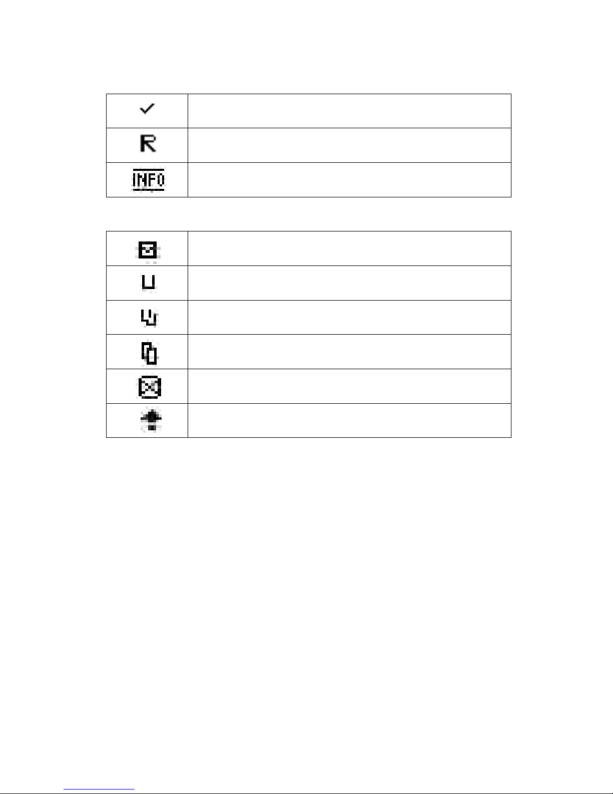
Appears when message sending is succeeded
Appears when device is roaming status
Appears when new news / Info message has been arrived
< Icons for message list >
Shows unread message
Shows read message
Shows duplicated read message
Shows duplicated read message
Shows sent failed message
Shows sending message
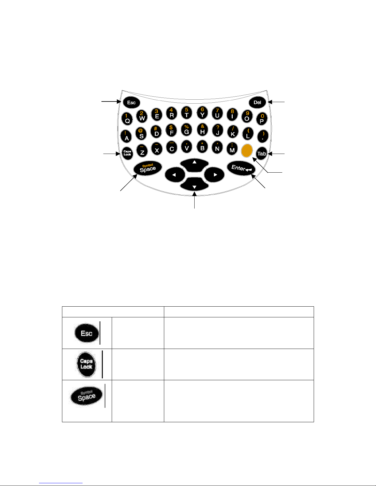
1.2 Keys Description
Control Buttons
Control Button Description
Escape
Press to return to preceding screen without accepting any changes.
Also, press to access the initial screen from the main menu screen
Caps
Lock
Press to capitalize for next typed letters.
Caps Lock- Pressing button two times activates the Caps lock
mode(uppercase letter). To exit, press again.
Symbol
/Space
Space: Press to insert a space in text.
Symbol: Pressing ALT key and then pressing Space key Activates
Symbols. Fourteen (14) symbols are available at the bottom of the
screen.
TAP
ALT
ENTER
NAVIGATION
SYMBOL
SPACE
CAPS
LOCK
DELETE
ESCAPE
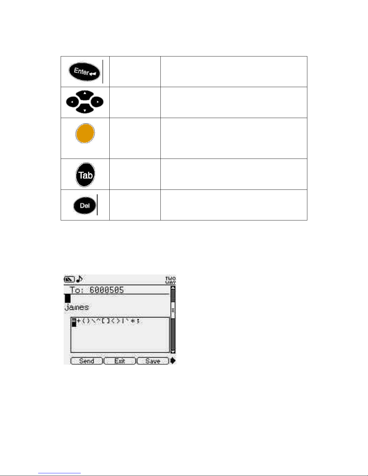
Enter
Press to select the highlighted option or to save settings.
Navigation
Press left, right, up, down buttons to move within a field (Text field,
list field, button field)
Alt
Activates the alt-mode control keys (color-coded amber). The next
key pressed activates an Alt-mode function.
Pressing Alt key two times activates Alt lock mode. To exit, press
again.
Tab
Moves the bottom menu field. From the text field, press Tab to
access the button field menu.
To exit, press ESC or up keys
Delete
Delete the character to the left of the cursor
Space / Symbol Display
Symbols can be used in all edit screens.
For example, symbol box appears when you press space in ALT mode as shown in below sample image.
Here, select the character you want with Left/Right to enter the corresponding characters.
How to use Keys
- Press TAB key to move to bottom menu and press ESC or Up key to exit.
- Use Navigation key to move a cursor. (Up, Down, Left, Right)
- Use Up or Down key to move in the upper box of list screen.

And use left or right key to view long text in the lower box.
- Always use Enter key to select.
1.3 Display in the initial screen
ß Status Icon Area
ß Owner’s name Area
ß Time & Date Area
ß Function Key Area
Function Key
Key : Go to Read menu directly
Key : Go to Write menu directly
Key : Go to Contact menu directly
Key : Go to Scheduler menu directly
* You can go to main menu by pressing any key with the exception of left, right, up and down keys.
Upper Box
Lower Box
Bottom Menu

1.4 Display in the Main menu screen
< Main menu icons >
Icon Description
Read Message
Write Message
Contact
Scheduler
Task
Memo
Preference
Calculator

Game
Preference
World Clock
Alert
Alarm
Lock
Tx Set
Mymail icon
1.4 LED INDICATOR
Your device LED radiates 3 Color light
l When new message arrived – Yellow Green Color
l During device charging with charger – Red Color
l When device complete charging – Green Color

2. Getting Started
2.1 How to switch device on and off
Press Power Button over 3 sec to switch device on
Press Power Button over 4 sec to switch device off
2.2 How to charge battery
Electric outlet
Travel Charger
HRD-100 Pager
- Plug your charger into a main socket first
- Connect the lead from the charger to the bottom of device
H200 Pager

l Battery Charging Indicator
Charging Complete Charging
Device LED Red light Green light
Charger Indicator Red light Green light
- The first charging must be for at least 2 hours in order to achieve optimum performance.
- Normally the device completes to charge the battery in one hour
- After complete charging, the device automatically checks the battery status during the
charger connector is installed on the device. Once it detect that the battery level is below full status, it
automatically recharge the battery.
- When you unplug your device from its charger, grasp and pull the plug, not the power cord.
- Your device turns off by itself if the battery is able to power no longer sufficiently
- You can send and receive message while charging your device.
- Standby time of battery may be reduced if device is in the No Network Service area
2.3 How to reset device
First, uncover rubber cap on the bottom of device and find reset switch which is colored blue. And
then, push reset switch to the right and return to the left again by using pointed tool.
Reset SwitchSerial Port
2.4 How to turn on backlight
Press Power Button for 2 sec to turn on backlight (Device must be turned on first)
2.5 How to lock keyboard
If you want to lock all keyboard, pull hold switch to down.
To exit, pull hold switch up.

3. Read Message
This application enables you to read and respond to incoming messages & Info, forward and delete
messages. It also allows you to manage inbox, Info, Draft, Personal / Business / Misc group, Outbox, Sent
and delete menu.
Figure Read-1 appears when you select Read in the menu screen.
Read menu has below 9 sub menus
< Figure Read-1 >
Move to the message folder you want using Direction key and press Enter key to move to the relevant
folder.
When a message arrives
Popup box appears as shown in Figure Recv-1 screen when you receive a message.
If the user wants to read a message at this time, select Yes to directly go to initial screen of Inbox as
shown in Figure Inbox-1 screen. If not, select No to go back to previous screen.
<Figure Recv-1>

3.1 Inbox
<Figure Inbox-1: Inbox MSGS>
Inbox folder saves all the messages received so far.
Upper box shows the message list and lower box shows the contents of message.
Up/Down direction key is used to move the message you want to read in the list.
And Left/Right Direction key is used to read the contents if the message is long.
Press Enter key while list is selected to display the screen in Figure Inbox-2.
And press TAB key to move the cursor to the bottom menu. Press Enter key to execute the function.
* Tip: For back tap, press ALT key and then press tap key.
<Figure Inbox-2: Message View>
You can read the message and select the function of bottom menu in Figure Inbox-2 screen.
This bottom menu is same as that of Figure Inbox-1.
Message List
Message Preview
Bottom Menu
Max character : 96

Feature of Bottom Menu
(1) Reply
<Figure Reply-1>
If you want to write a new message in Figure Reply-1, select the custom message menu in the upper most
menu to display the screen in Figure Reply-2. If you sends multi-choice or canned message, select the
message you want and press Enter. Then, popup box "Reply Send" appears shortly and disappears.
<Figure Reply-2>
If you select custom message, write the relevant message in Figure Reply-2 and select Send function in
the bottom menu to send the message. If you select Q-text in the bottom menu, the
list of text you entered in advance will appear as shown in the screen of Figure Qtext-1.
Max character : 1997

<Figure Qtext-1>
At this time, select the content you want to type, in order to enter into the main part of editor.
Refer to Qtext menu function of Preference.
(2) Forward
If you select Forward in the bottom menu, Figure Write-1 appears. From here, it is same as the
explanation of Write, and only difference with Forward is whether the contents of previous message exist
or not.
(3) Move
If you select this function, the screen of Figure Move-1 appears, where you can move the message you
select to the other group.
After selecting the group you want in three groups, press Enter key to move the message. Then, list screen
of previous groups appears again.
<Figure Move-1>

(4) Delete
Select this function to display popup box "delete now?" as shown in the Figure Delete-1.
At this time, select "Yes" if you want to delete, and "No" if you don't want to delete. Press Esc key to go
back to previous screen.
<Figure Delete-1>
3.2 Info
Info folder saves all Info messages from your service provider and display information data.
Select Info icon to display Figure Info-1. Regular information comes in this folder.
You can save up to 16 kinds of information. If you select Info you want to view, Figure Info-2 screen
appears.
Select the message you want in Figure Info-2 screen and press Enter key to display Figure Info-3 screen.
The bottom menu of Figure Info-2 and Figure Info-3 are the same. You can perform the function in the
bottom menu or any screen after selecting the message.
<Figure Info-1>
This icon shows that there is
unread news.

<Figure Info-2>
<Figure Info-3>
3.3 Draft
This folder is for the user to record and temporarily save the message.
If you select save function when you write a message, the message is saved in this folder. Initial screen is
as shown in the screen of Figure Draft-1.
If you want to delete the relevant item in Figure Draft-1 screen, select Delete in the bottom menu. At this
time, select "YES" when "delete now?" pops up.
If you want to move the relevant item to the message, select Send in the bottom menu.
Then, screen moves to the screen of Figure Write-1 and performs write function.
News List
News Preview
Bottom Menu

<Figure Draft-1>
If there is any item you want to modify, press Enter key in the relevant list to display the screen of Figure
Draft-2 where you can modify.
If you want to save after modifying in Figure Draft-2 screen, select the Save function in the bottom menu.
If you want to delete, select Delete.
If you want to send it to message, select Send of lower menu of Figure Draft-2 screen.
Then, the screen moves to the screen of Figure Write-1 and performs write function.
<Figure Draft-2>
3.4 Personal / Business / Misc
This folder is for the user to classify received message according to message kind.
Since above 3 groups have same function, the description will focus on one of them, personal group here.
First, select Personal icon to pop up various message list you moved to Personal from various folder. It is
as shown in Figure Personal-1.
Max character : 125

Since the function of bottom menu in Figure Personal-1 is same as Inbox, refer to how to use Inbox folder
described above.
<Figure Personal-1>
3.5 Outbox
This folder is to show the message currently being sent or the message that was not successfully sent.
When you select, screen of Figure Outbox-1 will appear.
Function of lower menu is similar to that of bottom menu of inbox. Difference is that Reply function is
left out, while Resend function is added.
Since Outbox has same function as Inbox, only Resend function will be explained here.
Select Resend in bottom menu to send the selected message again. However, it is not possible to resend
the message which is on sending process.
<Figure Outbox-1>
3.6 Sent

This folder is to show the message successfully sent.
Screen of Figure Sent-1 will appear when you select one message among the message list.
Function of bottom menu is same as the bottom menu function of outbox.
<Figure Sent-1>
3.7 Delete
This folder is to delete message data and display the screen of Figure Delete-1, Figure Delete -2.
This screen is to delete the storage box in a device all at once.
Select each storage box, and you will see a popup box "Storage box is deleted".
At this time, select Info group to pop up the kinds of Info as shown in Figure Delete-3. Select and delete
the kinds of Info you want here, and you will see a popup box "Info Deleted".
<Figure Delete-1> <Figure Delete-2>

<Figure Delete-3>

4. Write Message
This application enables you to compose messages using the QWERTY keyboard, insert Quick text and
other features.
Select Write in menu screen to pop up the screen of Figure Write-1. If there exists in the address book,
the recipient you want to send the message to, move to the relevant item and press Enter key to pop up
and select the check mark. When you select address item, the screen of Figure Write-2 appears so that
you can directly enter the address.
When you press Enter key after entering the address, the cursor moves to Compose in the lower menu. If
you want to select address continuously to send it to several recipients, press Up key to select address
continuously.
If you want to find the address of recipient whose name you know, type in the alphabet of the name. Then,
cursor will move to the relevant recipient.
For example, if you want to find recipient " Park jay" as shown in Figure find-1, type in park jay
regardless of lowercase or capital letter. Then, the cursor will move to the relevant user.
<Figure find-1>
Contact List
Find Contact
Bottom Menu
Max character : 11

<Figure Write-1> <Figure Write-2>
If you select new address, it will move to the screen of Figure Contact-2.1. Check how to use Contact for
reference.
After entering address, select the Save function. Then, it will return to the screen of Figure Write-1 and
checkmark appears in the new user data.
Bottom menu description
- List
When you select the list command in the bottom menu, the screen of Figure Write-3 appears.
This screen shows the list of the recipient.
- Delete
If you select several recipients and want to view the list, select the list in the lower menu to display the
screen in Figure Write-3. You can delete the user you don't want in the screen using the Delete function in
the lower menu.
<Figure Write-3>
- Return
Max character : 39

Select Return function in the lower menu to display the Figure Write-1 screen again.
- Exit
Return to the previous screen.
- Compose
If all selections are done, select Compose function in the lower menu to compose a message.
If you select Compose function, the screen of Figure Write-4 appears.
Following is the description about the bottom menu of Figure Write-4.
Functions of bottom menu in Figure Write-4
<Figure Write-4>
- Send
Modify the message as you want in Figure Write-4 screen and select Send in the bottom menu to send a
message to the recipient you selected.
- Save
Select the Save function in the lower menu in Figure Write-4 screen to move the message you currently
compose to the draft folder and then to the screen of Figure Write-1 again.
- Edit to
Edit to function enables to go back to the screen of Figure Write-1 screen and to add the user.
- Popup box "Discard changes?" appears if there is a message you currently compose. If you select Yes, it
goes back to the menu screen (Figure menu-1).
If you select No, it goes back to the screen you are working on.
- Qtext
Q-text function in the lower menu of Figure Write-4 screen was already explained in Figure Qtext-1.
- replies
If you select Replies function in the lower menu of Figure Write-4 screen, screen of Figure Write-5
appears.
Selected Contact
Compose Area
Bottom Menu
Max character : 124

In this screen, you can add multi-choice function. You can select one of several items when you send
reply to recipient.
You can enter up to 16 items. If you want to use this function, enter the data and select Save in the lower
menu to use this function. Then, the screen moves to the screen where you can compose a message.
<Figure Write-5>

5. Contact
This application enables you to store the address information of each person or group you might want to
contact. You can include Name, email address, work & home phone number and even address for each
contact entry.
5.1 Contact List (Screen showing the list of entered address)
<Figure Contact-1>
Contact List shows saved contact list and Contact preview shows the contents of selected contact list.
If there is any cursor in the List, use UP/DOWN arrow to move it to the location you want. In this case,
details are displayed in the bottom Preview Box.
If there are lots of contents in Preview Box, small triangle() will be displayed in the lower part of Box.
You can check the remaining contents in Preview Box using Left/Right arrow.
If you press Enter, you can move to Contact View screen (Figure Contact-3) and check the
overall contents. Enter Tab or Left/Right arrow Key while cursor is in the List, to move to the
bottom menu.
Contact List
Contact Preview
Bottom Menu
Max character : 40

<Figure Contact-1.2>
Bottom menu description
Selected menu is marked black when it is moved to the lower menu.
Use Tab Key to move to the bottom menu you want.
You can execute the selected menu using Enter Key. Use ESC Key to exit the lower menu.
Add New: Move to Contact New screen (Figure Contact-2.1) where you can enter new address.
Edit: Move to Contact Edit screen (Figure Contact-4.1) where you can edit the existing address.
Categ’s : Move to screen where you can selectively view specific category only (Figure Contact-5.1,
Contact-5.2, Contact-5.3).
Delete: Delete the address selected in the List.
Show as : It moves to 5.6 Name Type Screen.
5.2 New Contact (Screen for Entering New Address)
Max available character for each line is as below :
FIRST : 12 M Tel : 17 W adr : 98
LAST : 14 Fax : 17 W City : 20
WK mail : 38 Cmpny: 18 wSt/Zip : 12
Wireless:67 Title : 24 H adr : 98
Wk Tel : 17 Notes: 90 H City: 20
Hm Tel : 17 H St/Zip: 12

<Figure Contact-2.1> <Figure Contact-2.2> <Figure Contact-2.3>
New Contact is to input new contact contents and if you press Add new menu in the bottom menu, this
screen will displayed.
Use Up/Down arrow or Enter Key to move to the item you want and enter using the character and number
Key. In case of telephone number, you can enter number, #, (, ), x, - only.
If the cursor is placed on the last item, press Next in the bottom menu to move to the screen where you
can enter the address book (Figure Contact-2.2, Figure Contact-2.3).
Use Left/Right arrow or Tab Key to move to the menu you want and use Enter key to execute the selected
menu.
Use ESC Key to exit the lower menu.
Bottom menu description
Next: Move to the next screen where you can enter address book
Prev: Move to the previous screen where you can enter address book
Save: Save the currently entered contents in the address book
Cancel: Ignore the currently entered contents and go back to the Previous screen. (Address book list)
5.3 Contact View (Screen for Viewing Entered Address)
<Figure Contact-3>
Contact view shows full contents of each contact person. If there are lots of contents in View Box, use
Up/Down arrow to scroll the remaining contents in the box. If following list exists in the address, small

triangle () will be displayed in the lower part of Box. Use Left/Right arrow to move to the following
list. Press Tab Key to move to the lower menu.
Bottom menu description
Edit: Move to the Contact Edit screen (Figure Contact-4.1) where you can edit the existing address.
Snd Msg: Move to Write screen (Figure Write-1)
5.4 Edit Contact (Screen for Editing Entered Address)
<Figure Contact-4.1> <Figure Contact-4.2> <Figure Contact-4.3>
Edit Contact is for editing entered address.
Use Up/Down arrow or Enter Key to move to the item you want and enter using character and number
keys.
In case of phone number, you can enter number, #, (, ), x, - only.
If the cursor is placed on the last item, press Next in the bottom menu to move to the screen where you
can enter the address book (Figure Contact-4.2, Figure Contact-4.3).
Bottom menu description is same as bottom menu description of New Contact.

5.5 Contact Group (Screen for Listing Addresses by Group)
<Figure Contact – 5.1> <Figure Contact – 5.2> <Figure Contact – 5.3>
Contact group is to show classified contact list by group name – Personal / Business / General
Key operation and bottom menu description is same as Contact list.
5.6 Name Type
If Contact or Write icon is selected in the menu screen, the address you entered appears. It is used to sort
the name in the order.
<Figure Contact -6>
Move the cursor to the item you want as shown in Figure Contact -6, and press Enter key to select and
press Enter key again to save. You may press Esc key to cancel.

6. Scheduler
This application enables you to manage & record your schedule, view calendar and alarm function for
each saved schedule event.
6.1 Calendar (Screen for showing whether there exist Schedule and Task)
<Figure Scheduler – 1>
Use Up/Down, Left/Right arrow to move the box in the screen and to select the specific date.
If there exist schedule or task previously entered, the date is underlined.
If you press Enter key after moving the box to the underlined date, it moves to View Day screen (Figure
Scheduler - 3). Press Tab Key to move to the bottom menu.
Bottom menu description
SchEvt: Move to the screen (Figure Scheduler – 2) where you can enter new schedule.
PrevMo: Move to the previous month.
NextMo: Move to the next month.
Exit: Move to the previous screen.

6.2 New Schedule (Screen for Entering New Schedule)
If you press SchEvt in the bottom menu to input new schedule event, Figure Scheduler 2 screen will be
displayed.
<Figure Scheduler – 2>
<Figure Scheduler – 3>
Input Schedule title on event entry area and then set the start date & time and end date & time.
You can enter characters, numbers and symbols in Text field and number in date field.
If it is 12hour mode, AM/PM appears. Enter a or A to change to AM, and enter p or P to change to PM.
Alert feature enables you to set the time when alarm go off to inform you the event.
You can set the alert using left and right button and alert time is as below
1. None
2. On time
3. Before 5 min
4. Before 10 min
5. Before 20 min
6. Before 30 min
Repeat set area
Start / End date & time
Alert set area
Max character : 61
Event entry area

7. Before 1 hr
8. Before 2 hr
9. Before 4 hr
10. Before 12 hr
11. Before 1 day
12. Before 7 day
Repeat is to set the alarm repeatedly and you can set repeat mode using left and right key
Repeat mode has 5 options – Never / Daily / Weekly / Monthly / Yearly.
Use Esc Key to cancel the contents modified. Enter Tab Key to move to the bottom menu.
Bottom menu description
Save: Save the contents you entered.
Exit: Move to the previous screen.
6.3 View Day (Screen for Listing and Previewing Schedule and Task set up at the Selected Date)
<Figure Scheduler – 4>
If cursor is located in the list, use Up/Down arrow to move to the location you want. In this case, details
will be displayed in the lower Preview Box.
If there are lots of contents in Preview Box, small triangle() is displayed in the lower part of Box. Use
Left/Right arrow to check the remaining contents in Preview Box .
If you press Enter, it moves to Schedule Modification Screen (Figure Scheduler - 4) in case of Screen,
and Task Modification Screen (Figure Task-2) in case of Task.
While a cursor is located in the List, enter Tab Key to move to the lower menu.
Bottom menu description
Exit: Move to the previous screen.
Edit: Move to the screen for modifying the selected item.
Event list
Event Preview
Bottom Menu

Delete: Delete the selected item.
6.4 Edit Schedule (Screen for Modifying selected Schedule)
<Figure Scheduler – 5>
Bottom menu description
Save: Save the contents you modified
Cancel: Move to the previous screen.
Max character : 61

7. Task
This application enables you to manage & record your to do list. It shows due date, status and priority of
each to do list
<Figure Task – 1>
If cursor is located in the list, use Up/Down arrow to move to the location you want. In this case,
details will be displayed in the lower Preview Box.
If status is open, it will be marked as and if close, as as shown in Figure Task-1.
If there are lots of contents in Preview Box, small triangle() is displayed in the lower part of Box. Use
Left/Right arrow to check the remaining contents in Preview Box.
Press Enter to move to Task View screen (Figure Task - 3) and to check the overall contents.
While cursor is located in the List, Enter Tab Key to move to the bottom menu.
Bottom menu description
Add New: Move to the screen (Figure Task – 2) where you can enter new Task.
Edit: Move to the screen (Figure Task – 3) where you can modify the selected task.
Status: Change status of task selected.
Delete: Delete the selected task.
7.1 New Task (Screen for Entering New Task)
<Figure Task – 2>
Due date / Status / Priority set
Max character : 253
Max character : 30
Subject
Task Description
Task list
Task Preview
Bottom Menu

Input Task title on event subject area and then set the due date, Status, Priority of task and description of
task.
You can enter characters, numbers and symbols in Text field and number in date field.
Use Up/Down Key to move to the specific item.
You can use Left/Right Key to set status and priority.
Status has 2 options – Open / Close and Priority has 3 options – Low / Medium / High
Enter Tab Key to move to the bottom menu.
Bottom menu description
Save: Save the contents you entered
Cancel: Move to the previous screen.
7.2 Edit Task (Screen for Modifying Contents of Selected Task)
<Figure Task – 3>
Use Up/Down Key to move to the specific item.
You can enter characters, numbers and symbols in the Text field.
You can use Left/Right Key to select in case of Select Menu.
Enter Tab Key to move to the lower menu.
Bottom menu description
Update: Save the modified contents.
Delete: Delete the current Task.

8. Memo
This application enables you to record your memo and you can also send your saved memo as message to
others.
<Figure Memo – 1>
If cursor is located in the list, use Up/Down arrow to move to the location you want. In this case, details will be
displayed in the lower Preview Box.
If there are lots of contents in Preview Box, small triangle() is displayed in the lower part of Box. Use Left/Right
arrow to check the remaining contents in Preview Box.
Press Enter to move to Memo View screen (Figure Memo - 3) where you can check the overall contents.
While a cursor is located in the list, enter Tab Key to move to the lower menu.
Bottom menu description
Add New: Move to the screen (Figure Memo – 2) where you can enter new memo.
Edit: Move to the screen (Figure Memo – 3) where you can modify the selected Memo.
SndMemo: Move to the screen (Figure Write-1) where you can transmit the contents of selected memo as
a message and select the address you want.
Delete: Delete the selected memo
Memo List
Menu Preview
Bottom Menu

8.1 New Memo (Screen for Entering New Memo)
<Figure Memo – 2>
Use Up/Down Key to move to the specific item.
You can enter characters, numbers and symbols in the Text field.
Enter Tab Key to move to the lower menu.
Bottom menu description
Save: Save the contents you entered
Cancel: Move to the previous screen.
8.1 Edit Memo (Screen for Modifying Contents of Selected Memo)
<Figure Memo – 3>
Use Up/Down Key to move to the specific item.
You can enter characters, numbers and symbols in the Text field.
Enter Tab Key to move to the lower menu.
Bottom menu description
Update: Save the modified contents.
Delete: Delete the current Memo.
Memo Subject
Notes Area
Bottom Menu
Max character : 30
Max character : 253

9. Preference
This application provides various features that allow you to select various options and to execute several
functions.
Select Prefs in new screen to display Figure Prefs-1.
<Figure Prefs – 1>
9.1 Alert Settings
Change Sound and Alert in 1. Alert Settings.
<Figure Prefs – 2>
Use Up/Down Key to move to the specific item.
You can use Left/Right Key to select Alert field value you want.
Enter Up/Down Key to move the other menu.
After determining the strength with Left/Right key in Figure Prefs-5, press Enter to save or press Esc to
cancel.

1. Volume
Select 1. Volume when you adjust the volume in Figure Prefs-2.
You can select Low/Middle/High volume with Left/Right key in volume field,
2. Inbox, Info, Sch & Alm
You can select the preferable alert type using Left/Right key for Inbox, Info, Sch & Alm. These
Alert notice you when there is new message in inbox or new information in Info. or when it is time to
be alerted. You can listen the sound if you enter the Space key after selecting the Alert type your
want in Figure Prefs-2 with Left/rRight Key.
You can listen to the sound when you enter the Space key after selecting Alert you want in Figure Prefs-2
with Left/Right key
3. Reminder
If you want to remind the user to check the message in case when the user doesn't read the mail after it
arrives, use 3. Reminder Alert in Figure Prefs-2.
In Figure Prefs-2, select OFF/One Beep /Two Beep with Left/Right key in Reminder field,
4. R Interval
You can set the alert interval using Left/Right key and alert interval is as below
1. 1 min
2. 2 min
3. 5 min
4. 10 min
5. R Repeat
R Repeat is to set the alert repeatedly and you can set repeat mode using Left/Right key
.
Repeat mode has 4 options – 1 / 2 / 5 / 10 times.

9.2 Quick Text
Using Quick Text, you can easily put the words or shot message which are frequently used as shown in
2. Quick Text of Figure Prefs-3..
<Figure Prefs-3> <Figure Prefs-4> <Figure Prefs-5>
* New Quick Text
If you want to register new Quick text, select New Text field by pressing Enter key and it display as
Figure Prefs-4. Enter the text you want and press Enter key to register new text.
* Modify Quick Text
On the other hand, as shown in Figure Prefs-3, you can modify the registered text in the screen. Select the
Quick Text you want to modify and press Enter key as shown in in Figure Prefs-5. After modifying the
text you can move to the lower menu with Tab key to execute Update/Delete.
9.3 Private Time
If you want to stop the function that alerts whether the mail or Info are received for specific period of
time, select 3. Private Time in Figure Prefs-1 to display the screen as shown in Figure Prefs-6.
<Figure Prefs-6>
If you enter the number you want in Start/End field, it will display AM/PM if Time is 12 hour mode.
When a cursor is located in AM/PM, press A key to become AM, and press P key to become PM. Select
Max character : 61

ON/OFF in Set field with Left/Right key. Press Enter key when it is ON to activate private time function.
Mute icon will appear when it becomes the private time you set.
9.4 Setup
You can set up H200 in this menu.
<Figure Prefs-7>
9.4.1 Set Date & Time
If you want to set the current time of Device, select 1. Set Date & Time in Figure Prefs-7 to display
Figure Prefs-8.
<Figure Prefs-8>
If you want to set the time information transferred from the station as the time of your device, select
Sync mins field in Figure prefs-8 and select Enable. Move the cursor to the place you want with
Up/Down and press Left/Right key to select and press Enter key to save.
* Set Time
Select Time field if you want to directly enter the current time by yourself. As shown in Figure Prefs-8,
enter the value you want in Date and Time field. If Time is 12 hour mode, AM/PM appears. When a

cursor is placed on AM/PM, press A key to become AM, and press P key to become PM. Decide the
value in Sync mins/Date Format/Time Format field with Left/Right key.
Then, press Enter key to save the changed value and check the changed current time in the standby screen.
9.4.2 Display Settings
Select 2. Display Settings of Figure Prefs-7 to change the size of Font or LCD Contrast.
<Figure Prefs-9>
*Font
Select the size of font you want with Left/Right Key and press Enter to save. You may press Esc to cancel.
*Contrast
It is used to adjust LCD Contrast. Adjust contrast with Left/Right key as shown in Figure Prefs-9 and
press Enter key to set the value. You may press Esc to cancel.
9.4.3 Owner Information
It is to save simple information of Device user such as name and phone number. As shown in Figure
Prefs-10, enter the text you want and press Enter key to save.
<Figure Prefs-10>
Max character : 27

9.4.4 Signature
This function is used to attach the signature at the end of mail you transmit. Press 4.Signature in Figure
Prefs-7 to display Figure Prefs-11.
Select whether to Enable/Disable Display field with Left/Right key and enter the text you want in
Signature field. Press Enter key to save.
<Figure Prefs-22>
9.4.5 Title screen
You can put the Title screen you want for standby screen. Select 5.Title Screen Text in Figure Prefs-7
and press Enter.
<Figure Prefs-12>
As shown in Figure Prefs-12, type in the text you want and press Enter key to save. You may press Esc to
cancel.
9.4.6 Key Lock Password
It is used when you want to lock the device. Figure Prefs-13 appears when you select 6. Key Lock
Password in Figure Prefs-7.
Max character : 27
Max character : 15

<Figure Prefs-13>
In Figure Prefs-13, select Enable/Disable in lock field with Left/Right key and enter the 4 digit same
letters both in Password and Confirm Password field. If you don’t enter previous password exactly in Old
Password field, you'll see the screen of Figure Prefs-14.
The Password to be set from the factory is “0000”.
<Figure Prefs-14>
9.5 About
This application enables you to check the status of device such as current memory consumption, battery
level, carrier name and OS version
Select About in the preferences screen to display Figure Prefs -15.
<Figure Prefs -15>
Max character : 4

Current memory consumption, Battery level, carrier and S/W Version appear.
Press Esc key to exit.
9.6 Mymail Setup
It is used when you want to setup the Mymail communication. Select Mymail Setup to display Figure
Prefs -16.
<Figure Prefs -16>
Input your Mymail address on address area and then set ON/OFF with Left/Right Key.
You can enter characters, numbers and symbols in address field.
Select ON in set field if you want to use the Mymail communication.

10. Alarm
You can set the alarm date & time with this application.
<Figure Alarm-1>
Input alarm title on subject area and then set date & time.
You can enter characters, numbers and symbols in Text field and number in date field.
If it is 12hour mode, AM/PM appears. Enter a or A to change to AM, and enter p or P to change to PM.
Alarm enables you to set the time when alarm goes off.
You can set the alarm using Left/Right key and alarm can be set as below
None
On time
Before 30 min
Before 1 hr
Before 2 hr
Before 4 hr
Before 12 hr
Before 1 day
Before 7 day
Repeat is to set the alarm repeatedly and you can set repeat mode using left and right key
Repeat mode has 5 options – Never / Daily / Weekly / Monthly / Yearly.
Pop-up box as figure Alarm -2 will be displayed with Alarm. You can stop Alarm pressing Power
button or ESC key.
Max character : 19

<Figure Alarm -2>

11. Calculator
This application enables you to calculate using navigation keys
Select Calc in the menu screen to display Figure Calc-1.
<Figure Calc-1>
1. Direction (Up/Down, Left/Right) key, Space, Enter, Esc, Del and number key from 1~0 are used.
2. Press the number key you want and direction keys displaying addition, subtraction, multiplication and
division and repeat the process as shown above to press the number key. Press Enter key to view the
result.
3. If you want to calculate new formula again, press Space key and follow the process in number 3 above.
4. You can change the value by changing the unit of length. When you use it, enter the number you want
first and then Tab key. Select Con2ENG if you want English weights and measures, and Con2Met if you
want meter system (international unit) to display the converted value. Then, press Esc to go back to
Figure Calc-1.
Max character : 13

12. Lock
After Lock field is selected to Enable setting in Figure Prefs-13, If select Lock Menu, you'll see the screen
of Figure Lock-1.
<Figure Lock-1>
To release lock in Figure Lock-1, enter 4 digit password you entered in Password field in Figure Prefs-13.
Then, the lock will be released.

13. World Clock
This application enables you to check world clock with world map
Select W/Clock in the menu screen to display Figure W/Clock-1
<Figure W/Clock-1>.
1. World Clock View
Local time is displayed. Press left & right keys to move area and press Esc key to exit.
<Figure W/Clock-2>.
2. Set Time Zone
Move the cursor to 2 at Figure W/Clock-1 and press Enter to display Figure W/Clock-3.
Then, the user can select his own Time Zone with Direction key, and press Enter key to display the screen
where Time zone is selected. Press Enter again to save. When you press Esc key, it will ask whether to
cancel.
<Figure W/Clock-3>.

14. Game
This application enables you to play BLACK JACK game
Select Game in the menu screen to display Figure Game-1.
<Figure Game-1>
Press Enter here to display Figure Game-2.
<Figure Game-2>
* Betting
Change the Betting Money to the number you want using Up/Down key and press Enter Key to display
Figure game-3.
<Figure Game-3>
* Game Main

When Black Jack game starts, select whether to receive the card or not. If the game is over, the result is
displayed as shown in Figure Game-4. At this time, you can change the Betting Money with Up/Down
direction key and press Enter key to start new game.
If you press Esc key while you are playing, it will exit to Figure Game-1.
<Figure Game-4>

15. Tx Set
If the user wants to restrict the transmission at his discretion, select Tx Set and press Enter.
<Figure TxSet-1>
Here, move the cursor to the place you want, and press Enter to select. Press Enter again to save. You
may cancel it by pressing Esc. After you select Off and save it, tx/off will appear in the icon screen.

16. Alert
You can change the type of Alert pressing Enter Key,. Alert type status selected is displayed by Alert
Type Satus Icon (Silent, Sound and Vibrator) at Status Icon Area.

17. Mymail
.
<Figure Mymail-1> <Figure Mymail-2> <Figure Mymail-3>

18. H200 PC Link Program
1. Introducing H200 PC Link
• You can transfer and save device data to your PC via data cable.
• You can transfer and save following device data: Message (Inbox, Outbox,
Sent, Personal, Business, Miscellaneous) Data, Contact Data, Scheduler D
ata and Task Data to your PC
• You can delete saved Data (Message and Contact Data) on your PC
• You can edit and input new Contact Data on your PC and transfer edited
contact data from PC to device
• You can restore saved Data
2. Install and Uninstall
2.1 System Requirements
In order to connect properly with your device, your PC must meet the
following minimum requirements
• Windows 98, Windows NT 4.0, Window 2000 or Window XP must already be insta
lled on your PC
• 2MB of available storage on computer’s hard drive
• 16MB RAM
2.2 Install
1. Double Click “H200 link setup. exe” file and then follow instruction.
2. When setup is completed, click OK at each information window
3. Double Click H200 Link Program to start

2.3 Uninstall
• From the window start menu, select “Uninstall H200 Link”
3. How to connect data cable to your computer
Serial Port
Data Cable
HRD-100 Pager
Personal Computer
4. Using H200 PC Link
H - 200

<Picture 1>
<Picture 2>
Port Setting Schedule, Task
Menu
Display
Menu

<Picture 3>
* Note: Device must be connected with PC via Data cable and PC port must be
opened.
4.1 Port Open
• After connect data cable with PC, set the port and baud rate.
• Press Port Open button and then the circle of port open
will be changed this means your PC
port is opened successfully. If you select port which can not open, “Unable
open” message is displayed. In this case, select other port.
• After Port is opened, Backup button and Restore button will be
activated as follow
Progress Bar
Current
Backup display

4.2 Save
• After press Backup button , Picture 3 will be displayed and Backup starts.
• You can check Backup progress via Progress bar and current mode display
(Picture 3)
• If you want to stop backup, press button or
button.
• If you want to backup the Scheduler and Task, check
and press button
4.3 Restore
• After press button, picture 3 will be displayed and restore starts
• You can check Restore progress via Progress Bar and current mode display
(Picture 3)
• If you want to stop restore, press button or
button.
• If you want to restore Scheduler and Task, Check and
press button
4.4 Check Data
• After press button, picture 2 will be displayed and you can check saved
data.
• You can check data by pressing each menu button on menu area (Picture 2)
• You can edit contact data and also you can input new contact data by pre
ssing insert button

4.5 Delete Data
(1) Delete all data
Press button
(2) Delete special message folder or contact data
After Press button, picture 2 will be displayed.
Select message folder or contact button which you want to delete and then press
button.
(3) Delete each Data
Select data and press button

19. Device and Battery Care
1) Use only approved battery and power charger. Charging battery by any other method or unauthorized
product may cause damage to the battery
2) Keep in mind that a new battery’s full performance is achieved only after two or three times of
completed charging
3) The battery can be charged and discharged hundreds of times but it will eventually wear out. When the
operating time is noticeably shorter than normal, it is time to change to new battery.
4) Do not use device in the high temperature and humidity
5) Battery must be recycled or disposed of properly and never dispose of batteries in a fire.
6) Do not drop, knock and shake device
7) Do not use harsh chemicals, cleaning solvents, or strong detergents to clean device. Wipe it
with a soft cloth slightly dampened in a mild soap-and-water solution.
8) Do not attempt to open the casing on your device.
9) Do not expose device or charger to rain or snow. If device is flooded, never turn on power
and ask service center.

20. Trouble Shooting
1. Screen cannot be turned on at all.
It is because the batter is completely exhausted. Use it after charging.
2. Key is not pressed.
It is because Key is put on a hold. Release Hold Key.
3. When I turn on the power, it is turned off immediately.
Battery is completely discharged. Use it after charging.
4. I cannot hear the sound when I receive a message.
4.1 Your phone is set in Mute mode or the message receiving sound of Inbox is silent.
Select Melody in Pref-> 3. Sound Setting-> 3. Alert Types.
Select other sounds except Silent in Pref-> 3. Sound Setting-> 2. Alert-> 1. Inbox Alert.
4.2 If Private Time is set on and it is in that period, the sound will not occur. If you want to
release Private Time, select Off in Set Item in Pref-> 6. Private Time.
5. I cannot send a message.
Check whether it is in Two Way state at present.
If it is not Two Way status, it is stored in Outbox temporarily and will be automatically sent if it
is Two Way.
Contact your service provider if you still cannot send a message when it is in Two Way status.
6. I cannot see the screen clearly.
It is because Contrast is set too high or low.
Adjust it properly in Pref-> 10. Miscellaneous-> 3. Contrast.
7. I can see the screen but it does not operate at all.
Turn off the power by pressing Power Key in the upper left of the terminal for about 4 seconds
and then press that key again to turn it on.
If it still does not operate …
(Caution) It will result in deleting all the messages you saved.
Push off the Reset key to the right located at the right bottom of the terminal and push it off to
the left to turn it on.

8. Backlight is not turned on.
Press Power Key located at the upper left of the terminal for about 2 seconds.
9. I locked it but forgot the password.
(Caution) It will result in deleting all the messages you saved.
Push off the Reset key to the right located at the right bottom of the terminal and push it off to
the left to turn it on.
Initial Lock Password is ‘0000’.
10. The letter is too small.
It is because it is set as Small Font.
Select Small in Pref-> 4. Font.
11. I cannot write the letter I want, instead, symbol is written.
It is in Alt Lock mode. Press Alt key to release Alt mode.
12. Periodically, the date and time are incorrect.
Please go to preference menu of main screen and then select “8. Time and Date”
Select “1. Auto time setting” and set auto time setting off.
And set Date and Time on “2. Set time”
13. No SVC icon appears or Fail to send message
You probably are in the area out of the coverage of a ReFLEX network.

21. Safety Information
For the efficient and safe operation of your phone, observe these guidelines.
Pager Transmitter Safety
The FAA has regulations concerning the use of electric devices aboard aircraft.
When boarding an aircraft, turn your device off to avoid potential interference with aircraft radio
communication or navigation equipment.
In blasting zones or wherever it is forbidden to use it, set the TX mode to OFF. This prevents potential
transmission interference with sensitive equipment or explosives devices.
Using your device in a vehicle
Safety comes first, and is the ultimate responsibility of the driver. Please:
i) Give full attention to driving – driving safely is your first responsibility.
ii) If you receive message or want to write message during you drive vehicle, pull off the road
and park your vehicle before reading or writing a message in driving conditions so require.
For Vehicle Equipped with an Air Bag
Al air bag inflates with great force. Do not place objects, including both installed or portable wireless
equipment, in the area over the air bag or in the air bag development area. If in-vehicle wireless
equipment is improperly installed and the air bag inflates, serious injury could result.
Explosive Atmospheres and materials
Turn your device off when in any area with potential explosive atmospheres and obey all signs and
instructions. You must observe restrictions on the use of radio equipment in fuel depots; below deck on
boats; fuel or chemical transfer or storage facilities; areas where the air contains chemicals or particles,
such as grain, dust, or metal powders; areas with signs about explosive atmospheres or where blasting
operations are in progress; any other areas where you would normally be advised to turn off your vehicle
engines.

22. FCC Compliance Statement
This equipment has been tested and found to comply with the limits for a Class B Digital Device,
pursuant to Part 15 of the FCC Rules.
These limits are designed to provide reasonable protection against harmful interference in a residential
installation.
This equipment generates, uses and can radiate radio frequency energy and, if not installed and used in
accordance with the instruction, may cause harmful interference to radio communication.
However, there is no guarantee that interference will not occur in a particular installation. If this
equipment dose cause harmful interference to radio or television reception. Which can be determined by
turning the equipment off and on, the user is encouraged to try to correct the interference by one or more
of the following measures :
Reorient or relocate the receiving antenna.
Increase the separation between the equipment and receiver
---- Connect the equipment into an outlet on a circuit different from that to which the
receiver is connected
---- Consult the dealer or an experienced radio/TV technician for help.

SAR INFORMATION
THIS MODEL PHONE MEETS THE GOVERNMENT’S RE-QUIREMENTS FOR EXPOSURE TO
RADIO WAVES.
Your wireless phone is a radio transmitter and receiver. It is designed and manufactured not to exceed
limits for exposure to radiofrequency (RF) energy set by the Federal Communications the emission
Commission of the U.S. Government. These limits are part of comprehensive guidelines and establish
permitted levels of RF energy for the general population. The guidelines are based on standards that were
developed by independent scientific organizations through periodic and thorough evaluation of scientific
studies. The standards include a substantial safety margin designed to assure the safety of all persons,
regardless of age and health.
The exposure standard for wireless mobile phones employs a unit of measurement known as the Specific
Absorption Rate, or SAR. The SAR limit set by the FCC is 1.6 W/kg. * Tests for SAR are conducted with
the phone transmitting at its highest certified power level in all tested frequency bands. Although the SAR
is determined at the highest certified power level, the actual SAR level of the phone while operating can
be well below the maximum value. This is because the phone is designed to operate at multiple power
levels so as to use only the power required to reach the network. In general, the closer
you are to a wireless base station antenna, the lower the power output.
Before a phone model is available for sale to the public, it must be tested and certified to the FCC that it
does not exceed the limit established by the governmentadopted requirement for safe exposure. The tests
are performed in positions and locations (e.g., at the ear and worn on the body) as required by the FCC for
each model. The highest SAR value for this model phone when tested for use at the ear is 1.27 W/kg and
when worn on the body, as described in this user guide, is 0.685W/kg. (Body-worn measurements differ
among phone models, depending upon available accessories and FCC requirements). While there may be
differences between the SAR levels of various phones and at various positions, they all meet the
government requirement for safe exposure.
The FCC has granted an Equipment Authorization for this model phone with all reported SAR levels
evaluated as in compliance with the FCC RF exposure guidelines. SAR information on this model phone
is on file with the FCC and can be found under the Display Grant section of http://www.fcc.gov/oet/fccid
after searching on PP4TX-50C.

Additional information on Specific Absorption Rates (SAR) can be found on the Cellular
Telecommunications Industry Association(CTIA) web-site at http://www.wow-com.com.
* In the United States and Canada, the SAR limit for mobile phones
used by the public is 1.6 watts/kg (W/kg) averaged over one gram of
tissue. The standard incorporates a sub-stantial margin of safety to
give additional protection for the public and to account for any
variations in measurements.
 Loading...