

Humminbird XHS 6 24 User Manual
1
High Speed Transducer
THANK YOU
Thank you for choosing Humminbird, America’s #1 name in depthsounders. Humminbird has built its
reputation by manufacturing top-quality, thoroughly reliable marine equipment. Genuine Humminbird
accessories offer the opportunity to upgrade and expand the capabilities of your Humminbird product.
There are a number of ways to install a transducer on your boat.
ABOUT TRANSOM
MOUNT
INSTALLATION
BEFORE YOU START
The transom mount installation provides the least loss of signal since
the transducer is mounted outside the boat hull. This installation also
allows adjustment of both running angle and depth after the transducer
is mounted, which enables you to tune the installation for best results.
Transom Mounted Transducer
Following are instructions for the installation of the High Speed
Transducer. We encourage you to read these instructions carefully to
get full benefit from your Humminbird accessory.
If you find that items are missing from your installation kit, call our
Customer Resource Center Support Hotline. In addition to the
hardware supplied with your transducer, you will need a powered hand
drill and various drill bits, Phillips and flat-head screw drivers, a ruler or
measuring tape, pen or pencil, and Silicone sealant.
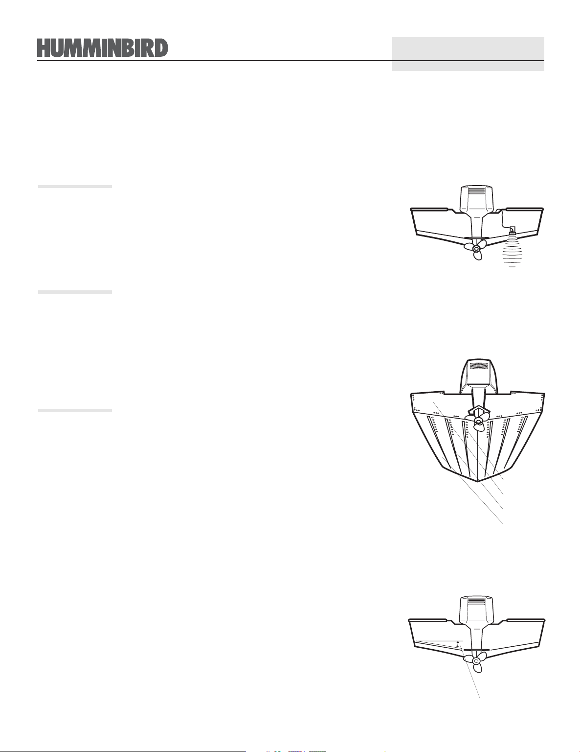
LOCATING THE TRANSDUCER
As a boat moves through the water, turbulence is generated by the
weight of the boat, and the thrust of the prop. This turbulent water is
normally confined to areas immediately aft of ribs, strakes, or rows of
rivets on the bottom of the boat, and in the immediate area of the
propeller(s). It is very important to locate the transducer in an area of
relatively turbulence-free water. If the prop(s) are forward of the
transom, it may be impossible to find an area clear from turbulence,
and a different mounting technique should be considered.
If possible, viewing the transom of the boat while the boat is moving
will provide the best means of locating clean water, and if maximum
high-speed operation is a high priority, this is the recommended
method. If this is not possible, select an area on the transom where the
hull forward of this location is smooth and free of protrusions or ribs.
Another consideration is the angle of deadrise. The transducer, when
mounted, should point straight down. The design of the transducer will
allow a deadrise of 15 degrees and remain pointed straight down.
Unlike many transducers, the XHS-6-24 has a hydrodynamic shape
that allows transom mount usage at angles greater than 15°. The sonar
return will be from directly below the boat at the transducers location.
Rivets
Transom
Strakes
Hull
Deadrise Angle
2
MOUNTING THE BRACKET
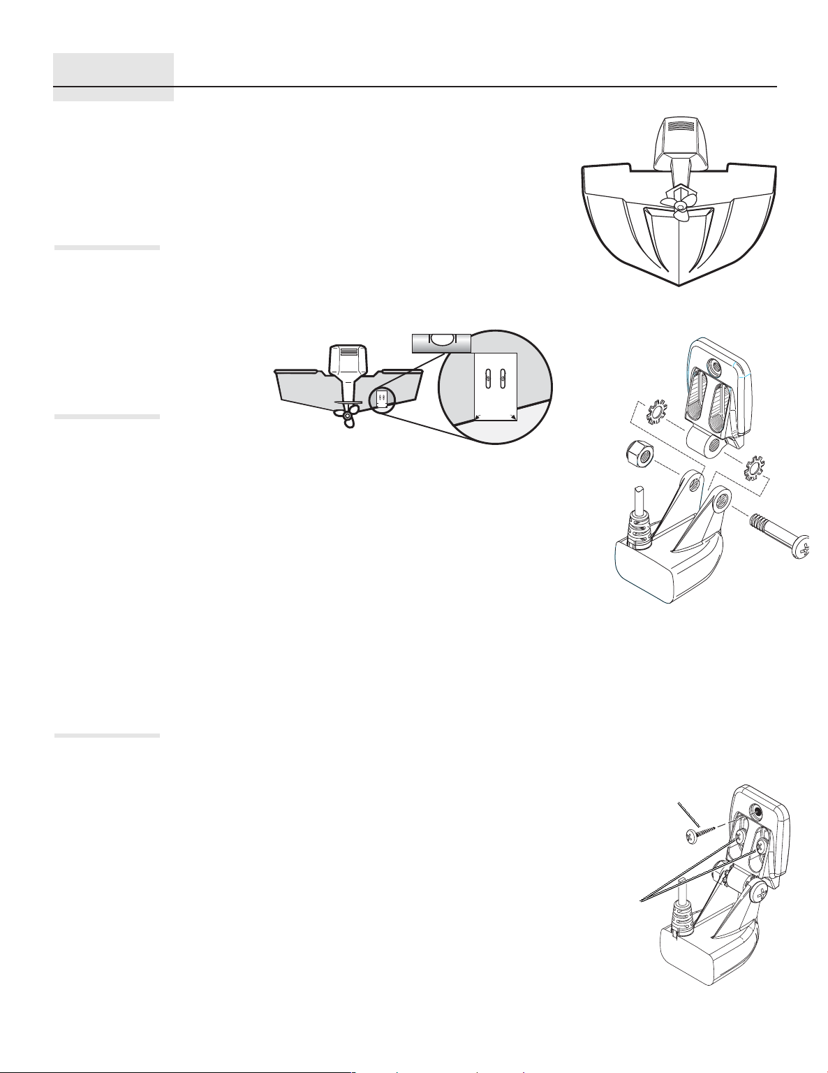
ASSEMBLING THE TRANSDUCER
ATTACHING THE
TRANSDUCER
On boats with stepped hulls, it may be possible to mount the
transducer on the step. Mounting the transducer on the transom
behind a step will reduce or make impossible high speed operation.
This area of the transom, behind a step, will not be in contact with the
water at high speed.
If the boat is trailered do not mount the transducer close to where
trailer bunks or rollers will impact with the transducer during loading
and unloading of the boat.
Ensure a turbulence free location at lease
15" from the prop(s) and not inline with
trailer bunks or rollers.
Level
TOP
Use 5/32" drill bit
DrillDrill
TOP
Use 5/32" drill bit
Drill Drill
DO NOT LET DEADRISE
INTERSECT THIS LINE
PLACE EITHER CORNER
ON DEADRISE ANGLE
PLACE EITHER ARROW
ON DEADRISE ANGLE
Once you have identified the location, use the mounting template on
page 4. This template locates the two mounting holes which must be
drilled. Note that there are two sets of holes, one for a fiberglass hull
and another set for an aluminum hull.
Hold the template on the transom of the boat in the location you
have selected. Align the template vertically.
Using a pencil or punch, mark the two mounting holes onto the
transom. Use the mounting bracket itself to confirm your marks.
Using a
⁵⁄₃₂"(4mm)
bit, drill the holes to a depth of approximately 1".
On fiberglass hulls, it is best to use progressively larger drill bits to
reduce the chance of chipping or flaking the outer coating.
The third hole should not be drilled until the angle and height of
the transducer is finalized.
Use a silicone sealant to fill the drilled holes, especially if the holes
penetrated the transom wall.
Attach the transducer body to the pivot as shown in the illustration at
right, using the Pivot bolt to couple the transducer ears to the
mounting bracket. The toothed washers must fit on the inside of the
transducer ears, between the pivot and the ears.
Use a #3 Phillips screw diver to hand tighten the transducer
assembly. Do not fully tighten the assembly at this time.
Stepped Hull
C
D
E
A – Mounting Bracket
B – Pivot
C – Star lock washers go between A & G.
D – Nut
E – Cable
¹⁄₄
F – Pivot Bolt
G – Transducer
Transducer Assembly
Drill and install the
third screw only after
final adjustments.
Use silicone
sealant to seal
the drilled holes
-20, #3 Phillips Drive
A
BB
C
F
G
Align the transducer assembly with the drilled holes in the transom.
Mount the transducer assembly to the transom using two wood
screws and washers as shown. Do not fully tighten the mounting
screws at this time.
Washers
&
Screws
Attaching the Bracket
 Loading...