

Page 1

hummer :: Hummer H1 V8-6.5L DSL (1998)
Page 2

> Relays and Modules > Relays and Modules - Powertrain Management > Relays and Modules - Computers and Control Systems > Engine Control Module > Component Information > Description and Operation
Engine Control Module: Description and Operation
POWERTRAIN CONTROL MODULE (PCM)
The PCM controls operation of all of the engine and transmission outputs. It is on a bracket attached to floor under the center console. The data linkconnector is the access point for the scan tool. The connector is under the instrument panel at the left side of the steering column. It is a multi-pinconnector with integral mounting bracket.
Signal inputs used by the PCM include:
- Coolant temperature
- Intake air temperature
- Boost/baro pressure
- Optical/fuel temperature sensor
- Crankshaft position sensor
- Accelerator pedal position sensors (APP)
- Cruise control
- A/C request
- Vehicle speed sensor
- Automatic transmission fluid pressure manual valve position switch
- Transmission input speed sensor
- Transfer case low range switch
- Transmission fluid temperature sensor
- Diagnostic request
Page 3

Page 4
> Relays and Modules > Relays and Modules - Powertrain Management > Relays and Modules - Glow Plug System > Glow Plug Relay > Component Information > Locations
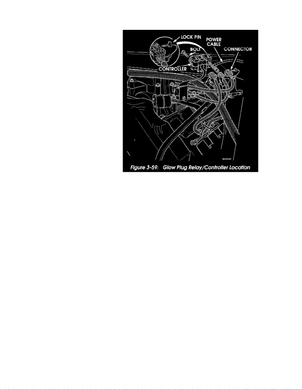
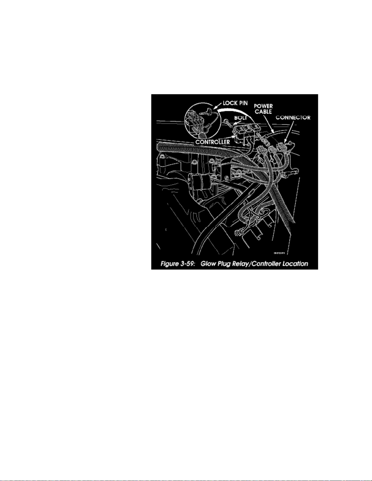
Figure 3-59: Glow Plug Relay/Controller Location
Page 5

Page 6
> Relays and Modules > Relays and Modules - Powertrain Management > Relays and Modules - Glow Plug System > Glow Plug Relay > Component Information > Locations > Page 12
Glow Plug Relay: Service and Repair
GLOW PLUG RELAY/CONTROLLER REPLACEMENT
1. Disconnect battery ground cable.2. Remove console and engine cover.3. Disconnect power cable at relay/controller (Figure 3-59)
Figure 3-59: Glow Plug Relay/Controller Location
4. Disengage three connectors from glow plug controller.5. Remove retaining bolt and remove relay.6. Position relay/controller on bracket and install attaching hardware.7. Engage connectors in relay/controller.8. Connect power cable to relay/controller stud.9. Install engine cover and console.
10. Connect battery ground cable.
Page 7

Page 8
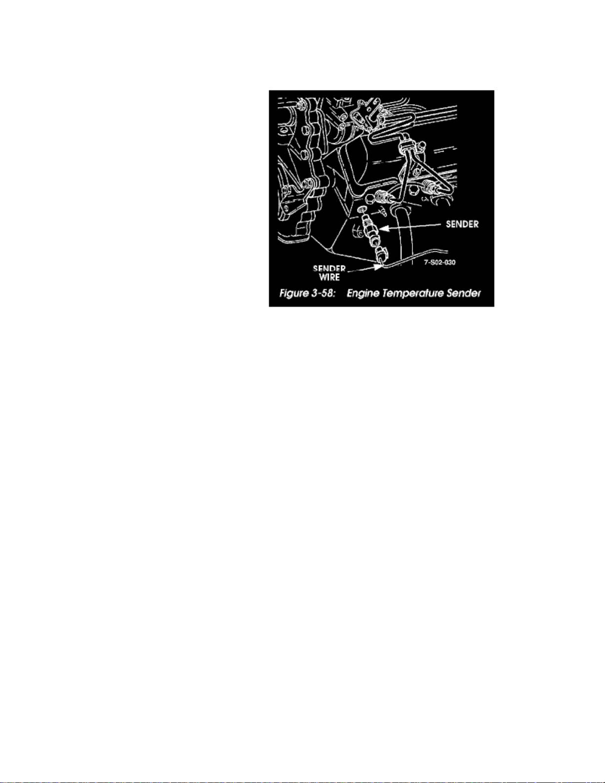
> Sensors and Switches > Sensors and Switches - Cooling System > Engine - Coolant Temperature Sensor/Switch > Coolant Temperature Sensor/Switch (For Computer) > Component Information > Locations
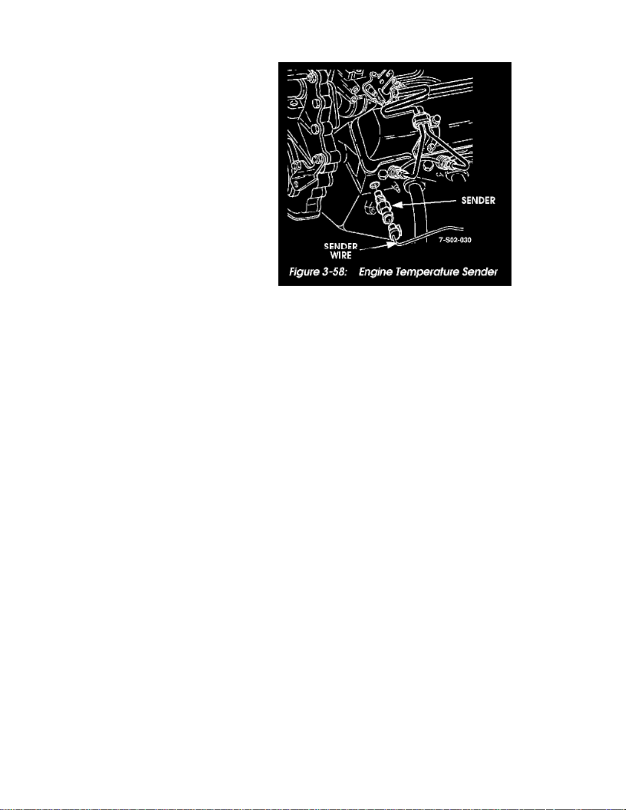
Figure 3-58: Engine Temperature Sender
Page 9

Page 10

> Sensors and Switches > Sensors and Switches - Cooling System > Engine - Coolant Temperature Sensor/Switch > Coolant Temperature Sensor/Switch (For Computer) > Component Information > Locations > Page 19
Coolant Temperature Sensor/Switch (For Computer): Diagrams
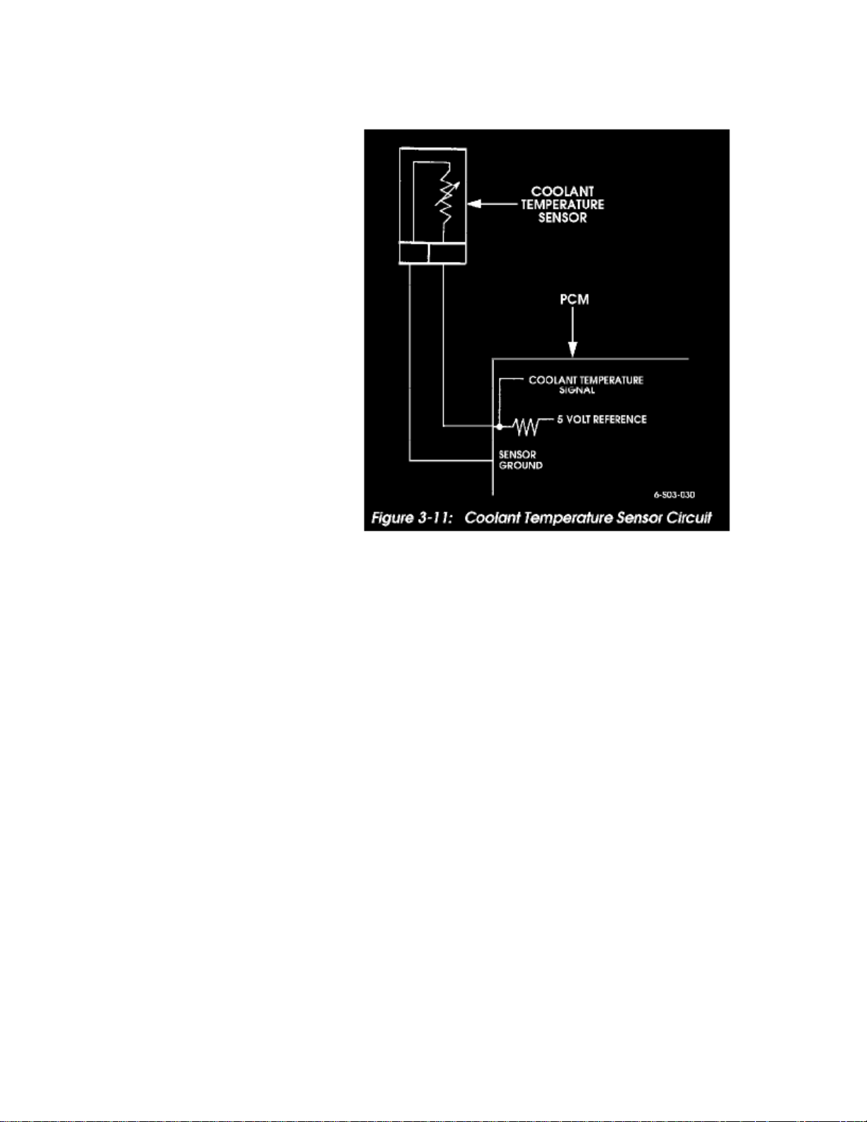
Figure 3-11: Coolant Temperature Sensor Circuit
Page 11

Page 12
> Sensors and Switches > Sensors and Switches - Cooling System > Engine - Coolant Temperature Sensor/Switch > Coolant Temperature Sensor/Switch (For Computer) > Component Information > Locations > Page 20
Coolant Temperature Sensor/Switch (For Computer): Description and Operation
Figure 3-11: Coolant Temperature Sensor Circuit
Engine Coolant Temperature Sensor Test
The coolant temperature sensor is a thermistor that provides a temperature signal to the PCM (Figure 3-11). The signal is in the form of a voltage thatchanges according to sensor resistance. At low temperatures, resistance and voltage are both high. As temperature increases, resistance and voltage bothdecrease.
A sensor fault will cause the check engine light to illuminate and the torque converter clutch to apply early. If the sensor fails in a cold mode, it canproduce overrich operation and rough idle.
Page 13

Page 14

> Sensors and Switches > Sensors and Switches - Cooling System > Engine - Coolant Temperature Sensor/Switch > Coolant Temperature Sensor/Switch (For Computer) > Component Information > Locations > Page 21
Coolant Temperature Sensor/Switch (For Computer): Testing and Inspection
Figure 3-11: Coolant Temperature Sensor Circuit
Engine Coolant Temperature Sensor Test
The coolant temperature sensor is a thermistor that provides a temperature signal to the PCM (Figure 3-11). The signal is in the form of a voltage thatchanges according to sensor resistance. At low temperatures, resistance and voltage are both high. As temperature increases, resistance and voltage bothdecrease.
A sensor fault will cause the check engine light to illuminate and the torque converter clutch to apply early. If the sensor fails in a cold mode, it canproduce overrich operation and rough idle.
High Temperature-Low Resistance Test
- If indicated temperature is 266 F (130 C) or above, continue test.
- If indicated temperature agrees with ambient, sensor is OK.
3. Disconnect sensor and note temperature indicated on scan tool:
- If indicated temperature drops to -22 F (-30 C), sensor has failed and should be replaced.
- If indicated temperature does not drop, problem is with sensor wiring or connections.
Low Temperature-High Resistance Test
1. Connect scan tool and start engine.2. Note indicated temperature:
- If temperature is normal, problem is with sensor wires and connections.
Page 15

1. Allow engine to cool down. Coolant should be at ambient temperature for test.2. Connect scan tool, start engine, and note sensor temperature.
- If temperature is at or above 266 F (130 C), continue with test. Disconnect sensor wires and note scan tool reading:
- If temperature now reads -22 F (-30 C), sensor has failed.
- If temperature is OK, problem is faulty sensor ground, reference wire shorted to ground, or PCM has fault.
Page 16
> Sensors and Switches > Sensors and Switches - Cooling System > Engine - Coolant Temperature Sensor/Switch > Coolant Temperature Sensor/Switch (For Computer) > Component Information > Locations > Page 22
Coolant Temperature Sensor/Switch (For Computer): Service and Repair
Figure 3-58: Engine Temperature Sender
ENGINE TEMPERATURE SENDER REPLACEMENT
1. Remove nut, lockwasher, lead, and sender from engine (Figure 3-58).2. Apply teflon sealant to sender threads, and install sender, lead, lockwasher, and nut on engine (Figure 3-58).
Page 17

Page 18

> Sensors and Switches > Sensors and Switches - Cooling System > Engine - Coolant Temperature Sensor/Switch > Temperature Switch (Warning Indicator) > Component Information > Locations
Temperature Switch (Warning Indicator): Locations
The coolant temperature switch is in the water crossover.
Page 19

Page 20
> Sensors and Switches > Sensors and Switches - Instrument Panel > Fuel Gauge Sender > Component Information > Service and Repair
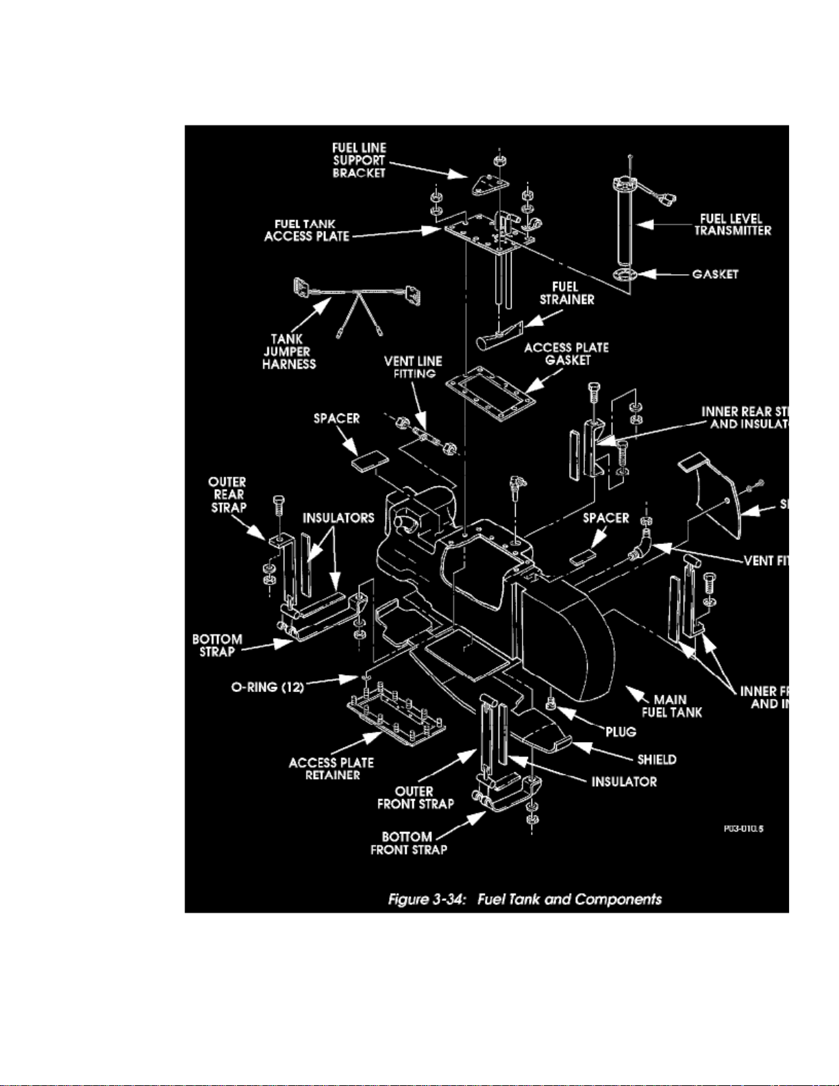
Fuel Gauge Sender: Service and Repair
Figure 3-34: Fuel Tank and Components
Page 21

> Sensors and Switches > Sensors and Switches - Instrument Panel > Fuel Gauge Sender > Component Information > Service and Repair > Page 30
H1 V8-6.5L DSL (1998)
Page 22
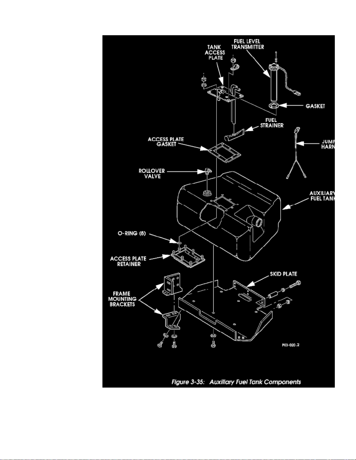
Figure 3-35: Auxiliary Fuel Tank Components
FUEL LEVEL TRANSMITTER AND TANK ACCESS PLATE SERVICE
Page 23

> Sensors and Switches > Sensors and Switches - Instrument Panel > Fuel Gauge Sender > Component Information > Service and Repair > Page 31
H1 V8-6.5L DSL (1998)
Removal
1. Remove screws, lockwashers and fuel level transmitter from tank access plate (Figures 3-34 and 3-35).2. Remove locknuts, washers, access plate and gasket from tank.3. Remove access plate retainer and O-rings from tank. Discard O-rings.
Page 24
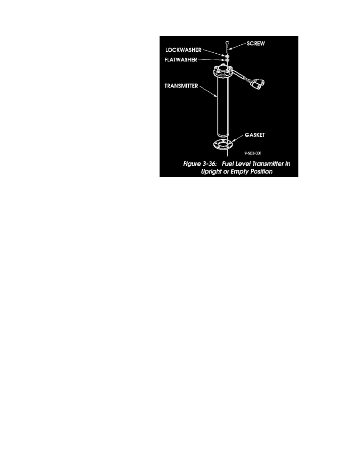
Figure 3-36: Fuel Level Transmitter in Upright or Empty Position
Check fuel level transmitter operation as follows:
1. Hold transmitter in the upright or empty position (Figure 3-36).2. Using an ohmmeter, check resistance value at terminals. Resistance should be 268 20 Ohms.3. Hold transmitter in the inverted position simulating a full tank. Resistance should fall to 19.3 8 Ohms.
Installation
CAUTION: Do not overtighten access plate or transmitter fasteners. Gasket damage and improper sealing could result.
1. Thoroughly clean all gasket surfaces.2. Place new O-rings on access plate retainer studs and position access plate retainer in tank (Figures 3-34 and 3-35).3. Set gasket and access plate over studs and onto tank.4. Apply liquid teflon thread sealant to studs and loosely install washers and locknuts until no clearance exists between access plate, gasket and tank.5. Snug access plate locknuts in small increments and in a systematic circular pattern. Tighten locknuts until gasket bulges or until maximum torque
of 72 lb-in. is obtained.
6. Apply liquid teflon thread sealant to transmitter mounting screws.7. Secure gasket and transmitter to access plate using same method as indicated for access plate above.8. Cap all tank fittings and perform leak check. Apply leak check solution or soapy water around access plate and transmitter gaskets and fasteners.
Pump 3 p.s.i. of compressed air into tank and verify absence of leaks.
Quick Connect Fittings
Quick connect fittings are used at the main tank fuel tubes, auxiliary tank fuel tubes, and at the fuel tank selector valve.
Two types of fittings are used. One type is an all plastic push on style with removable retainer. The second style is a metal, one-piece fitting with aninternal tension clip to retain it. The plastic fitting retainer only requires a screwdriver and needle-nose pliers to remove. The metal fitting requires arelease tool, such as J 37088-A, in order to disconnect it.
The metal fittings are used at the main tank. The plastic, two-piece fittings are used at the auxiliary tank and fuel selector valve.
Metal Fittings
Page 25

1. To disconnect, slide the release tool onto the line and into the fitting.2. Press the tool inward to unseat the internal clip and pull the line off the fuel tube.3. To reconnect, just push the fitting onto the line until it snaps or clicks into place.4. Pull on the fitting afterward to verify proper seating.
Plastic Fittings
1. To disconnect, raise the retainer tab with a small flat blade screwdriver and remove the retainer with needle-nose pliers.2. To reconnect, push the fitting onto the tube, insert the retainer through the fitting sides, and seat it firmly.3. Be sure the retainer seats behind the fuel tube flange.4. Pull on the fitting afterward to verify proper seating.
Page 26

> Sensors and Switches > Sensors and Switches - Instrument Panel > Temperature Switch (Warning Indicator) > Component Information > Locations
Temperature Switch (Warning Indicator): Locations
The coolant temperature switch is in the water crossover.
Page 27

Page 28
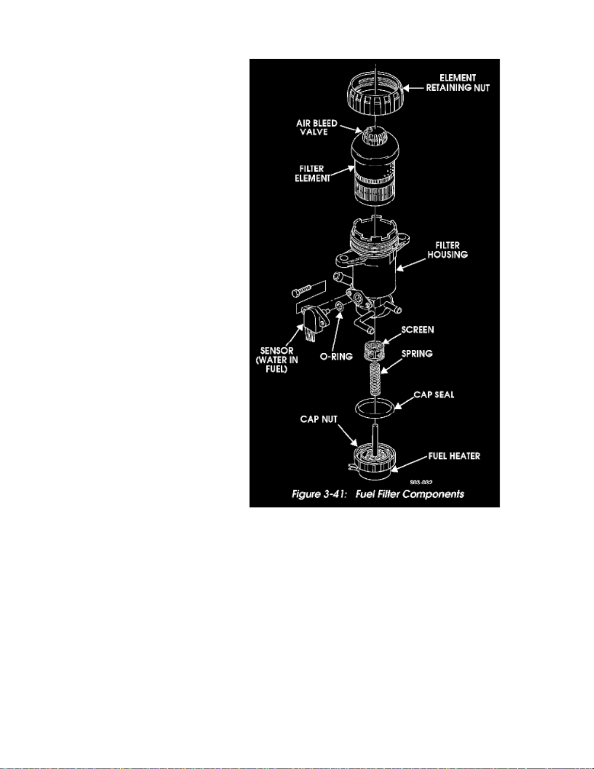
> Sensors and Switches > Sensors and Switches - Instrument Panel > Water In Fuel Sensor > Component Information > Locations
Figure 3-41: Fuel Filter Components
Page 29

Page 30
> Sensors and Switches > Sensors and Switches - Powertrain Management > Sensors and Switches - Computers and Control Systems > Accelerator Pedal Position Sensor > Component Information > Locations
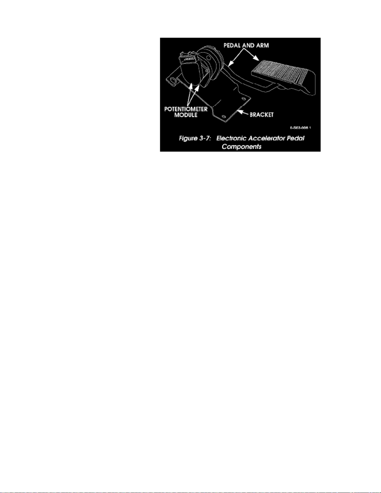
Figure 3-7: Electronic Accelerator Pedal Components
Page 31

Page 32

> Sensors and Switches > Sensors and Switches - Powertrain Management > Sensors and Switches - Computers and Control Systems > Accelerator Pedal Position Sensor > Component Information > Locations > Page 43
Accelerator Pedal Position Sensor: Description and Operation
Figure 3-7: Electronic Accelerator Pedal Components
Figure 3-8: Electronic Accelerator Pedal (Location)
Figure 3-9: Accelerator Pedal Connector Clip
Electronic Accelerator Pedal
Page 33

Turbo diesel models are equipped with an electronic accelerator pedal assembly (Figure 3-7). The assembly consists of a pedal and arm, mountingbracket, and potentiometer module. The pedal assembly mounts in a conventional location.
The pedal potentiometer module contains three potentiometers that send varying voltage signals to the PCM. By comparing the different voltage signalsagainst a standard, the PCM can determine fuel delivery rate based on accelerator pedal position.
A "check throttle" warning light is used to alert the driver of a problem with the pedal assembly.
Some faults in the pedal potentiometer module or related wiring will trigger the check throttle warning light. The light is located in the status center.Some faults will cause loss of cruise control only and multiple faults in the APP circuit can result in decreased performance or engine idle only.
Page 34

> Sensors and Switches > Sensors and Switches - Powertrain Management > Sensors and Switches - Computers and Control Systems > Accelerator Pedal Position Sensor > Component Information > Locations > Page 44
Accelerator Pedal Position Sensor: Testing and Inspection
Figure 3-22: Electronic Accelerator Pedal Module Circuitry
Electronic Accelerator Pedal Tests
The pedal module contains three potentiometer-type sensors that provide voltage signals to the PCM. Each potentiometer is scaled differently to providevarying voltage signals. The PCM compares the voltage variance between them to determine throttle position (Figure 3-22).
A fault in only one of the potentiometer sensors will not cause a trouble code to set. Two or more sensors must develop a fault before the check throttlelight will illuminate.
A fault in two sensors will cause the warning light to illuminate and engine power will be limited by the PCM. A fault in all three sensors, will cause thePCM to illuminate the light and limit engine speed idle rpm only.
Trouble codes will set under the following circumstances:
- Two sensors generate voltage of 4.75 volts or more for a minimum of two seconds.
- Two sensors generate a voltage of 0.25 volts or less for a minimum of two seconds.
- Voltage difference between sensors 1 and 2 of 6% or more.
- Voltage difference of 10% or more, between sensors 1, 2, and 3.
- Fault in all three sensors (above or below normal signal voltage).
The Tech 1 scan tool is required for accurate sensor diagnosis. However, the sensor circuit wires can be tested for shorts, opens, grounds with 12 volttest lamp and/or multimeter.
Page 35

Page 36

> Sensors and Switches > Sensors and Switches - Powertrain Management > Sensors and Switches - Computers and Control Systems > Barometric Pressure Sensor > Component Information > Description and Operation
Barometric Pressure Sensor: Description and Operation
Baro Sensor
The baro sensor on turbo diesel models is used to send a barometric pressure signal to the PCM. The signal is in the form of a voltage that is interpretedby the PCM. The sensor signal is to adjust fuel metering and timing at different altitudes. The scan tool is used for baro sensor testing.
Page 37

Page 38

> Sensors and Switches > Sensors and Switches - Powertrain Management > Sensors and Switches - Computers and Control Systems > Coolant Temperature Sensor/Switch (For Computer) > Component Information > Locations
Figure 3-58: Engine Temperature Sender
Page 39

Page 40

> Sensors and Switches > Sensors and Switches - Powertrain Management > Sensors and Switches - Computers and Control Systems > Coolant Temperature Sensor/Switch (For Computer) > Component Information > Locations
> Page 51
Coolant Temperature Sensor/Switch (For Computer): Diagrams
Figure 3-11: Coolant Temperature Sensor Circuit
Page 41

Page 42

> Sensors and Switches > Sensors and Switches - Powertrain Management > Sensors and Switches - Computers and Control Systems > Coolant Temperature Sensor/Switch (For Computer) > Component Information > Locations
> Page 52
Coolant Temperature Sensor/Switch (For Computer): Description and Operation
Figure 3-11: Coolant Temperature Sensor Circuit
Engine Coolant Temperature Sensor Test
The coolant temperature sensor is a thermistor that provides a temperature signal to the PCM (Figure 3-11). The signal is in the form of a voltage thatchanges according to sensor resistance. At low temperatures, resistance and voltage are both high. As temperature increases, resistance and voltage bothdecrease.
A sensor fault will cause the check engine light to illuminate and the torque converter clutch to apply early. If the sensor fails in a cold mode, it canproduce overrich operation and rough idle.
Page 43

Page 44

> Sensors and Switches > Sensors and Switches - Powertrain Management > Sensors and Switches - Computers and Control Systems > Coolant Temperature Sensor/Switch (For Computer) > Component Information > Locations
> Page 53
Coolant Temperature Sensor/Switch (For Computer): Testing and Inspection
Figure 3-11: Coolant Temperature Sensor Circuit
Engine Coolant Temperature Sensor Test
The coolant temperature sensor is a thermistor that provides a temperature signal to the PCM (Figure 3-11). The signal is in the form of a voltage thatchanges according to sensor resistance. At low temperatures, resistance and voltage are both high. As temperature increases, resistance and voltage bothdecrease.
A sensor fault will cause the check engine light to illuminate and the torque converter clutch to apply early. If the sensor fails in a cold mode, it canproduce overrich operation and rough idle.
High Temperature-Low Resistance Test
- If indicated temperature is 266 F (130 C) or above, continue test.
- If indicated temperature agrees with ambient, sensor is OK.
3. Disconnect sensor and note temperature indicated on scan tool:
- If indicated temperature drops to -22 F (-30 C), sensor has failed and should be replaced.
- If indicated temperature does not drop, problem is with sensor wiring or connections.
Low Temperature-High Resistance Test
1. Connect scan tool and start engine.2. Note indicated temperature:
- If temperature is normal, problem is with sensor wires and connections.
Page 45

1. Allow engine to cool down. Coolant should be at ambient temperature for test.2. Connect scan tool, start engine, and note sensor temperature.
- If temperature is at or above 266 F (130 C), continue with test. Disconnect sensor wires and note scan tool reading:
- If temperature now reads -22 F (-30 C), sensor has failed.
- If temperature is OK, problem is faulty sensor ground, reference wire shorted to ground, or PCM has fault.
Page 46

> Sensors and Switches > Sensors and Switches - Powertrain Management > Sensors and Switches - Computers and Control Systems > Coolant Temperature Sensor/Switch (For Computer) > Component Information > Locations
> Page 54
Coolant Temperature Sensor/Switch (For Computer): Service and Repair
Figure 3-58: Engine Temperature Sender
ENGINE TEMPERATURE SENDER REPLACEMENT
1. Remove nut, lockwasher, lead, and sender from engine (Figure 3-58).2. Apply teflon sealant to sender threads, and install sender, lead, lockwasher, and nut on engine (Figure 3-58).
Page 47

Page 48

> Sensors and Switches > Sensors and Switches - Powertrain Management > Sensors and Switches - Computers and Control Systems > Crankshaft Position Sensor > Component Information > Diagrams
Figure 3-20: Crankshaft Position Sensor Circuit
Page 49

Page 50

> Sensors and Switches > Sensors and Switches - Powertrain Management > Sensors and Switches - Computers and Control Systems > Crankshaft Position Sensor > Component Information > Diagrams > Page 58
Crankshaft Position Sensor: Description and Operation
Figure 3-20: Crankshaft Position Sensor Circuit
Crankshaft Position Sensor
The crankshaft position sensor is a Hall-effect device that monitors crankshaft position and rpm. Four reference teeth 90 apart, on the crankshaft timingsprocket cause the devise to turn "ON" or "OFF" producing a digital signal. This occurs as each tooth passes near the sensor magnetic field turning thesensor "ON". The sensor transmits information to the PCM in the form of a 5 volt digital signal.
A sensor fault will cause a "crank reference missed" reading to occur. The scan tool will display the number of reference pulses missed. Normal readingis zero.
If a sensor fault occurs, check the sensor wiring and connectors for shorts, opens, grounds, or loose connectors (Figure 3-20).
Sensor Test
1. Disconnect wires at fuel shut-off solenoid.2. Connect voltmeter between PCM terminal BRA5 and ground and crank engine.
- If meter indicates 5 volts, sensor is OK.
- If meter indicates less than 5 volts or zero volts, check 5 volt reference at PCM terminal BRD13.
- If 5 volt reference is OK, problem is bad connection or failed sensor.
Page 51

Page 52

> Sensors and Switches > Sensors and Switches - Powertrain Management > Sensors and Switches - Computers and Control Systems > Crankshaft Position Sensor > Component Information > Diagrams > Page 59
Crankshaft Position Sensor: Testing and Inspection
Figure 3-20: Crankshaft Position Sensor Circuit
A sensor fault will cause a "crank reference missed" reading to occur. The scan tool will display the number of reference pulses missed. Normal readingis zero.
If a sensor fault occurs, check the sensor wiring and connectors for shorts, opens, grounds, or loose connectors (Figure 3-20).
Sensor Test
1. Disconnect wires at fuel shut-off solenoid.2. Connect voltmeter between PCM terminal BRA5 and ground and crank engine.
- If meter indicates 5 volts, sensor is OK.
- If meter indicates less than 5 volts or zero volts, check 5 volt reference at PCM terminal BRD13.
- If 5 volt reference is OK, problem is bad connection or failed sensor.
Page 53

Page 54

> Sensors and Switches > Sensors and Switches - Powertrain Management > Sensors and Switches - Computers and Control Systems > Diesel Fuel Temperature / Fuel Pump Position Combination Sensor > Component
Information > Locations
Figure 3-5: Electronic Fuel Injection Pump
Page 55

Page 56

> Sensors and Switches > Sensors and Switches - Powertrain Management > Sensors and Switches - Computers and Control Systems > Diesel Fuel Temperature / Fuel Pump Position Combination Sensor > Component
Information > Locations > Page 63
Diesel Fuel Temperature / Fuel Pump Position Combination Sensor: Diagrams
Figure 3-15: Optical/Fuel Temperature Sensor Circuit
Page 57

Page 58

> Sensors and Switches > Sensors and Switches - Powertrain Management > Sensors and Switches - Computers and Control Systems > Diesel Fuel Temperature / Fuel Pump Position Combination Sensor > Component
Information > Locations > Page 64
Diesel Fuel Temperature / Fuel Pump Position Combination Sensor: Description and Operation
Figure 3-15: Optical/Fuel Temperature Sensor Circuit
Optical/Fuel Temperature Sensor Tests
The optical/fuel temperature sensor supplies three signals to the PCM for fuel control and timing. A high resolution signal helps determine injectiontiming and fuel control. A pump cam signal provides reference pulses that monitor and help determine injection timing. The fuel temperature signal helpsthe PCM determine pump advance or retard requirements and fuel flow. The sensor is located at the top of the injection pump adjacent to the fuelshut-off solenoid.
A fault in the optical sensor or related wiring will produce fast idle and performance problems. A problem will cause a high resolution circuit fault, or acam reference pulse error fault.
The sensor can be checked with a scan tool.
Page 59

Page 60

> Sensors and Switches > Sensors and Switches - Powertrain Management > Sensors and Switches - Computers and Control Systems > Diesel Fuel Temperature / Fuel Pump Position Combination Sensor > Component
Information > Locations > Page 65
Diesel Fuel Temperature / Fuel Pump Position Combination Sensor: Testing and Inspection
Figure 3-15: Optical/Fuel Temperature Sensor Circuit
Optical/Fuel Temperature Sensor Tests
A fault in the optical sensor or related wiring will produce fast idle and performance problems. A problem will cause a high resolution circuit fault, or acam reference pulse error fault.
The sensor can be checked with a scan tool and a voltmeter as follows:
High Resolution Fault Test
1. Turn ignition off.2. Disconnect sensor harness connector.3. Turn ignition on.4. Connect voltmeter to sensor terminal A, of the harness, and to ground.
- If meter indicates 5 volts, continue with test.
- If meter indicates zero voltage, look for open/short in wire to PCM 5 volt reference terminal, connector, or PCM.
5. Connect volt/ohmmeter to a good engine ground and to sensor ground terminal D:
- If resistance is .2 Ohms or less, proceed to next test step.
- If resistance is greater than .2 Ohms, problem is with ground wire, connector, or sensor.
Page 61

Page 62

> Sensors and Switches > Sensors and Switches - Powertrain Management > Sensors and Switches - Computers and Control Systems > Intake Air Temperature Sensor > Component Information > Locations
Intake Air Temperature Sensor: Locations
The MAP and air temperature sensors are at the passenger side of the intake manifold.
Page 63

Page 64

> Sensors and Switches > Sensors and Switches - Powertrain Management > Sensors and Switches - Computers and Control Systems > Manifold Pressure/Vacuum Sensor > Component Information > Locations
Manifold Pressure/Vacuum Sensor: Locations
The MAP and air temperature sensors are at the passenger side of the intake manifold.
Page 65

Page 66

> Sensors and Switches > Sensors and Switches - Powertrain Management > Sensors and Switches - Computers and Control Systems > Oil Temperature Sensor For ECM > Component Information > Locations
Oil Temperature Sensor For ECM: Locations
The oil pressure switch is in the valley between the heads.
Page 67

Page 68

> Sensors and Switches > Sensors and Switches - Powertrain Management > Sensors and Switches - Fuel Delivery and Air Induction > Accelerator Pedal Position Sensor > Component Information > Locations
Figure 3-7: Electronic Accelerator Pedal Components
Page 69

Page 70

> Sensors and Switches > Sensors and Switches - Powertrain Management > Sensors and Switches - Fuel Delivery and Air Induction > Accelerator Pedal Position Sensor > Component Information > Locations > Page 79
Accelerator Pedal Position Sensor: Description and Operation
Figure 3-7: Electronic Accelerator Pedal Components
Figure 3-8: Electronic Accelerator Pedal (Location)
Figure 3-9: Accelerator Pedal Connector Clip
Electronic Accelerator Pedal
Page 71

Turbo diesel models are equipped with an electronic accelerator pedal assembly (Figure 3-7). The assembly consists of a pedal and arm, mountingbracket, and potentiometer module. The pedal assembly mounts in a conventional location.
The pedal potentiometer module contains three potentiometers that send varying voltage signals to the PCM. By comparing the different voltage signalsagainst a standard, the PCM can determine fuel delivery rate based on accelerator pedal position.
A "check throttle" warning light is used to alert the driver of a problem with the pedal assembly.
Some faults in the pedal potentiometer module or related wiring will trigger the check throttle warning light. The light is located in the status center.Some faults will cause loss of cruise control only and multiple faults in the APP circuit can result in decreased performance or engine idle only.
Page 72

> Sensors and Switches > Sensors and Switches - Powertrain Management > Sensors and Switches - Fuel Delivery and Air Induction > Accelerator Pedal Position Sensor > Component Information > Locations > Page 80
Accelerator Pedal Position Sensor: Testing and Inspection
Figure 3-22: Electronic Accelerator Pedal Module Circuitry
Electronic Accelerator Pedal Tests
The pedal module contains three potentiometer-type sensors that provide voltage signals to the PCM. Each potentiometer is scaled differently to providevarying voltage signals. The PCM compares the voltage variance between them to determine throttle position (Figure 3-22).
A fault in only one of the potentiometer sensors will not cause a trouble code to set. Two or more sensors must develop a fault before the check throttlelight will illuminate.
A fault in two sensors will cause the warning light to illuminate and engine power will be limited by the PCM. A fault in all three sensors, will cause thePCM to illuminate the light and limit engine speed idle rpm only.
Trouble codes will set under the following circumstances:
- Two sensors generate voltage of 4.75 volts or more for a minimum of two seconds.
- Two sensors generate a voltage of 0.25 volts or less for a minimum of two seconds.
- Voltage difference between sensors 1 and 2 of 6% or more.
- Voltage difference of 10% or more, between sensors 1, 2, and 3.
- Fault in all three sensors (above or below normal signal voltage).
The Tech 1 scan tool is required for accurate sensor diagnosis. However, the sensor circuit wires can be tested for shorts, opens, grounds with 12 volttest lamp and/or multimeter.
Page 73

Page 74

> Sensors and Switches > Sensors and Switches - Powertrain Management > Sensors and Switches - Fuel Delivery and Air Induction > Fuel Tank Selector Switch > Component Information > Description and Operation
Fuel Tank Selector Switch: Description and Operation
Figure 3-39: Fuel Lines, Connections, and Attachment
FUEL SELECTOR VALVE
The selector valve is used on models equipped with an auxiliary fuel tank (Figure 3-39). The valve is electrically operated by a switch in the passengercompartment. The switch will be mounted on the instrument panel.
Valve function is to switch fuel supply from main to auxiliary tank (and back) when needed.
Quick connect fittings are used to attach each of the six fuel lines to the valve. The plastic, two-piece style fittings are used.
Page 75

The valve is mounted on a bracket attached to the passenger side frame rail. Valve position is forward of the fuel tank and B-pillar area.
The valve is not a serviceable part and must be replaced when diagnosis indicates this is necessary.
Page 76

> Sensors and Switches > Sensors and Switches - Powertrain Management > Sensors and Switches - Fuel Delivery and Air Induction > Fuel Tank Selector Switch > Component Information > Description and Operation > Page
84
Fuel Tank Selector Switch: Service and Repair
Figure 3-39: Fuel Lines, Connections, and Attachment
Selector Valve Replacement
The valve is accessible from under the vehicle. Disconnect the battery and remove the valve-to-bracket bolts first. Then disconnect the fuel lines one at atime and tag them for reference. Last, disconnect the valve-to-switch harness and remove the valve. Reverse the process to install the valve.
Page 77

Page 78

> Sensors and Switches > Sensors and Switches - Powertrain Management > Sensors and Switches - Fuel Delivery and Air Induction > Turbo Boost Sensor > Component Information > Locations
Turbo Boost Sensor: Locations
The boost pressure switch is on the passenger side valve cover.
Page 79

Page 80

> Sensors and Switches > Sensors and Switches - Powertrain Management > Sensors and Switches - Fuel Delivery and Air Induction > Turbo Boost Sensor > Component Information > Locations > Page 88
Turbo Boost Sensor: Diagrams
Figure 3-21: Boost Sensor Circuit
The PCM supplies the boost sensor with a 5 volt reference signal (Figure 3-21).
Page 81

Page 82

> Sensors and Switches > Sensors and Switches - Powertrain Management > Sensors and Switches - Fuel Delivery and Air Induction > Turbo Boost Sensor > Component Information > Locations > Page 89
Turbo Boost Sensor: Description and Operation
Figure 3-21: Boost Sensor Circuit
Boost Sensor
The PCM supplies the boost sensor with a 5 volt reference signal (Figure 3-21). Changes in intake manifold pressure will cause a change in boost sensorresistance values and voltage. The PCM determines turbocharger boost by comparing changing sensor voltage to the original reference voltage. A sensorfailure will result in loss of turbocharger boost and consequent power decrease. Trouble code P0237 or P0238 will be set.
Page 83

Page 84

> Sensors and Switches > Sensors and Switches - Powertrain Management > Sensors and Switches - Fuel Delivery and Air Induction > Turbo Boost Sensor > Component Information > Testing and Inspection > Boost Sensor
Circuit Test
Turbo Boost Sensor: Testing and InspectionBoost Sensor Circuit Test
Figure 3-21: Boost Sensor Circuit
Boost Sensor Circuit Test
1. Connect scan tool to diagnostic/data link connector.2. Start and run engine at idle speed.3. Record boost sensor voltage.
- If voltage is 4.0 volts or more, continue test.
-
If voltage is less than specified, compare sensor to known good one. Voltage should not vary by more than plus or minus 0.4 volt. If sensorvoltage compares favorably with known good sensor, problem is in wiring or connections.
4. Turn ignition off and disconnect boost sensor wires.5. Turn ignition switch back on (engine off), and note scan tool voltage reading.
- If boost voltage is 1 volt or less, continue test.
- If voltage is less than specified, problem is in wiring or connections between sensor and PCM.
6. Connect 12 volt test lamp between sensor terminal C and battery positive post.
- If lamp illuminates, problem is with sensor, connectors, or fitting.
- If lamp does not illuminate, problem is open wire.
Page 85

Page 86

> Sensors and Switches > Sensors and Switches - Powertrain Management > Sensors and Switches - Fuel Delivery and Air Induction > Turbo Boost Sensor > Component Information > Testing and Inspection > Boost Sensor
Circuit Test > Page 92
Turbo Boost Sensor: Testing and InspectionBoost Sensor Performance Check
Boost Sensor Performance Check
This check requires the scan tool to be connected, the engine running at curb idle rpm, and the transmission in Park.
At idle or at closed throttle decel, a properly functioning sensor will indicate a pressure reading about the same as barometric pressure. Sensor voltage (ifany), should be low.
Sensor pressure readings should increase as throttle opening is increased. Voltage readings should also increase.
Boost pressure readings are opposite what you would read for vacuum. For example, as throttle opening increases, sensor pressure readings will alsoincrease. Vacuum readings on the other hand, will decrease as throttle opening increases.
Page 87

Page 88

> Sensors and Switches > Sensors and Switches - Powertrain Management > Sensors and Switches - Ignition System > Crankshaft Position Sensor > Component Information > Diagrams
Figure 3-20: Crankshaft Position Sensor Circuit
Page 89

Page 90

> Sensors and Switches > Sensors and Switches - Powertrain Management > Sensors and Switches - Ignition System > Crankshaft Position Sensor > Component Information > Diagrams > Page 97
Crankshaft Position Sensor: Description and Operation
Figure 3-20: Crankshaft Position Sensor Circuit
Crankshaft Position Sensor
The crankshaft position sensor is a Hall-effect device that monitors crankshaft position and rpm. Four reference teeth 90 apart, on the crankshaft timingsprocket cause the devise to turn "ON" or "OFF" producing a digital signal. This occurs as each tooth passes near the sensor magnetic field turning thesensor "ON". The sensor transmits information to the PCM in the form of a 5 volt digital signal.
A sensor fault will cause a "crank reference missed" reading to occur. The scan tool will display the number of reference pulses missed. Normal readingis zero.
If a sensor fault occurs, check the sensor wiring and connectors for shorts, opens, grounds, or loose connectors (Figure 3-20).
Sensor Test
1. Disconnect wires at fuel shut-off solenoid.2. Connect voltmeter between PCM terminal BRA5 and ground and crank engine.
- If meter indicates 5 volts, sensor is OK.
- If meter indicates less than 5 volts or zero volts, check 5 volt reference at PCM terminal BRD13.
- If 5 volt reference is OK, problem is bad connection or failed sensor.
Page 91

Page 92

> Sensors and Switches > Sensors and Switches - Powertrain Management > Sensors and Switches - Ignition System > Crankshaft Position Sensor > Component Information > Diagrams > Page 98
Crankshaft Position Sensor: Testing and Inspection
Figure 3-20: Crankshaft Position Sensor Circuit
A sensor fault will cause a "crank reference missed" reading to occur. The scan tool will display the number of reference pulses missed. Normal readingis zero.
If a sensor fault occurs, check the sensor wiring and connectors for shorts, opens, grounds, or loose connectors (Figure 3-20).
Sensor Test
1. Disconnect wires at fuel shut-off solenoid.2. Connect voltmeter between PCM terminal BRA5 and ground and crank engine.
- If meter indicates 5 volts, sensor is OK.
- If meter indicates less than 5 volts or zero volts, check 5 volt reference at PCM terminal BRD13.
- If 5 volt reference is OK, problem is bad connection or failed sensor.
Page 93

Page 94

> Maintenance > Tune-up and Engine Performance Checks > Fuel Pressure > System Information > Specifications
Fuel Pressure: Specifications
Fuel Pump Pressure Test
Fuel pump pressure ............................................................................................................................................................ 5.8-8.7 psi (40-60 kPa) at idle.
Page 95

Page 96

> Maintenance > Tune-up and Engine Performance Checks > Fuel Pressure > System Information > Specifications > Page 104
Fuel Pressure: Testing and Inspection
Fuel Pump Pressure Test
Fuel pump pressure should be 5.8-8.7 psi (40-60 kPa) at idle.
1. Disconect fuel line at fuel filter inlet port.2. Install a tee adapter in fuel line between pump and filter inlet port.3. Connect test gauge to tee adapter. Gauge should have pressure capacity up to 20psi (138kPa).4. Start and run engine and record fuel pump pressure.5. If pump pressure is less than 5.8psi (40kPa), replace pump and retest pressure.6. Remove pressure gauge and tee adapter. Reconnect fuel line to filter inlet.
Page 97

Page 98

> Maintenance > Tune-up and Engine Performance Checks > Air Cleaner Housing > Air Filter Element > Component Information > Service and Repair
Air Filter Element: Service and Repair
Cleaning and Inspection
Replace air filter if plugged or saturated with dirt. Clean hose and dust unloader with shop towels. Clean other components with solvent and examine forwear or damage. Replace worn, damaged parts if necessary.
Page 99

> Maintenance > Tune-up and Engine Performance Checks > Air Cleaner Housing > Air Filter Element > Component Information > Service and Repair > Page 109
H1 V8-6.5L DSL (1998)
Figure 3-23: Air Cleaner Assembly and Dust Unloader
Page 100

Figure 3-24: Air Cleaner Fitter Element Removal/Installation
Air Cleaner Filter Element Service
Removal
1. Remove ring clamp, cover, and gasket from air cleaner (Figure 3-24).2. Remove nut and washer assembly and filter element from air cleaner stud.
Inspection
1. Clean components with compressed air, examine for wear or damage, and replace if necessary.2. Remove dust or sand by gently tapping around filter element.3. Remove dirt and dust from filter element by directing flow of compressed air from inside to outside of filter element.
Installation
1. Slide filter element onto air cleaner stud and install nut and washer. Tighten nut and washer to 18-35 lb-in. (2-4 N.m) (Figure 3-24).
To avoid damage to hood, ensure ring clamp bolt is between the three and six o'clock positions.NOTE:
2. Install gasket, cover, and ring clamp on air cleaner assembly. Tighten ring clamp bolt to 27-35 lb-in. (3-4 N.m).
 Loading...