


INSTALLATION & MAINTENANCE INSTRUCTIONS
MODEL SW-2
Your humidifier has been designed and engineered to
give, with proper care, many years of trouble free
service. Therefore, if this unit ceases to operate
properly, we suggest you contact your local dealer. If
we, at Humidity Source, can be of any assistance to
you, please feel free to write, call or e-mail.
IMPORTANT
This space type humidifier is designed so that it may
be shelf mounted. The shelf should be at least 18”
(45.7cm) below the ceiling and 6 feet (1.8m) above
floor. The directional vapor dome should be positioned
to diffuse moisture without striking any obstructions
closer than six feet and maintain 24” minimum between
each side of the humidifier and any wall or obstruction.
PROCEDURE
Run a water supply line using 1/4” o.d. copper or
plastic tubing or 1/8” pipe. Keep the line to the rear of
the unit to avoid creating an obstruction.
Flush water feed lines before making final connection
to avoid having cutting oil, pipe scale, or chips which
may clog the float valve.
Turn on water valve, adjust water level to 1” below the
overflow connection.
Adjustment is easily made using the adjusting thumb
screw for higher or lower water level as illustrated.
SERVICE & REPAIR
Should this humidifier need service or repair some time
in the future, return only atomizing unit direct to the
factory.
CARE OF THE MACHINE
Due to air washing while the humidifier is in operation,
a deposit of dirt and dust may settle in the bottom of
the water reservoir and screen, and it is recommended
that both be cleaned regularly.
24”
Top View
24”
IN ROOM MOUNTED HUMIDIFIER
Periodically the atomizing unit should be taken from
the reservoir and given a careful visual check. The
pump tube should be spun by hand to make sure that it
is free to revolve without binding. See maintenance
instructions.
Shut –off
valve
¼” water
supply
¼” comp.
connection
water supply
¼” female pipe
overflow connection
to drain
Typical Installation
No obstruction within
the dimensions indicated to
prevent wetting objects.
Ceiling
18”
6’ Minimum
To Wall
6’ Minimum
To Floor
WIRING
The atomizer motor draws .67 Amps at 115 Volts A.C.
single phase and 60 Hz service.
Provide standard electric receptacle to receive electric
cord from humidifier. Have the hot leg of service to this
receptacle wired in series with the humidistat terminals
and use a standard disconnect switch if required. See
wiring diagram.
This humidifier may be run continuously or operated by
means of a humidistat.
Our standard human hair element humidistat model P825 is correct for most applications maintaining up to
60% RH.
For humidors and other high humidity applications, or
for more precise control, use the electronic humidistat
model W351A. This model also has an optional digital
display module to indicate the set point and the actual
R.H. in the room.
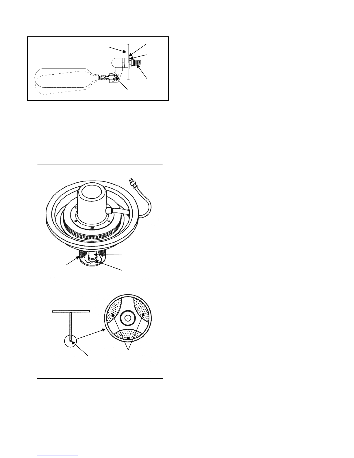
Screen
Remove impeller
cap
Reservoir Wall
Float Valve Operation
Pressure Range 10-150 psig
Atomizing Unit
1-A
1-B
Sight into bottom
These openings
must be clear
Adjusting
Thumb Screw
Pump Tube
Impeller Cap
of tube
1-C
Mounting
Washer
Mounting
Nut
1/8” MPT
OPERATION
Positive capacity atomizing humidifiers produce a mist that
will quickly evaporate into the air if there is no impingement
of water particles against barrier surfaces before the water
particles against barrier surfaces before the water is
completely absorbed. Strict attention to minimum clearance
dimensions must be adhered to in order to avoid
condensation.
MAINTENANCE
Unplug electric cord & remove dome. Carefully lift atomizing
unit out of reservoir (Figure 1). Hold atomizing unit firmly
and remove the perforated screen (1-A) by turning it slightly
to the left until the four lugs are in line with the slots. To
remove the impeller cap (1-B), hold a flat file or the back of a
table knife flat against the side of the tube and gently tap the
cap which is held in place by a pressed fit. After the cap has
been removed, the inside of the tube is visible and it is
simple matter to clean it with a piece of cloth on the end of a
screwdriver or a small round brush.
There are three ports through which water makes its way
from the pump tube to the top of the rotating disc (1-C).
These ports should be cleaned out with the aid of a wire.
See drawing on this page.
Replace the impeller cap by tapping it evenly back into
place, using plastic handle on screwdriver.
Remove water from reservoir & rinse. Fill reservoir with
white vinegar or other mild acid solution. Replace dome &
atomizer on reservoir & block outlet of dome with plastic
wrap & a rubber band. Run atomizer for ½ hour or until
minerals are completely dissolved. If necessary, rinse with
diluted chlorine bleach solution. Rinse with clean water and
return to service. For hard water problems, see
“demineralized water” below.
Inspect float valve assemble periodically, & replace when
necessary, or every few years.
DEMINERALIZED WATER
If local water supply has a high mineral content, (call water
company & ask for “total dissolved solids” or T.D.S.) This
mineral will create tiny particles of airborne “white dust”
when the mist evaporates in the air.
To eliminate this dust, use an ion exchange or a reverse
osmosis demineralizer. See Humidity Source data sheets
for “DI” & “RO” demineralizing filters.
Figure 1

C
er
W351 Humidistat
Electronic Sensor
COM
PWR
OUT
Wiring Diagram If Using P-825 Humidistat Installation
Humidifi
Receptacle
Humidity Source P-825
Wall Humidistat
120 VAC
L1
L
2
Neutral Hot
H
L
W351A Wiring Diagram If Using W351 On/Off Controller
Controller Power Module Digital Display
W351A Y350R D351
COM
VDC
SEN
120 VAC
To Humidifier

y
MODEL SW-2 REPLACEMENT PARTS
Description Part Number
Dome Strap Assembly 079590
Dome 905026
Channel Rubber 905582
Atomizing Assembly WF/525/9/2
Rubber Mounts (3) 80096
Impeller Cap 905587
Cylindrical Screen 905543
P-825 Humidistat
Human Hair Element
Standard
Humidifier Accessories
W351 Humidistat
Electronic Sensor
For high humidity
And/or close
tolerances
Float Valve Assembly 079057
Reservoir 905608
Humidity Source Reverse Osmosis water
Treatment systems. Sizes range from industrial
capacities down to individual room units.
Humidity Source LLC 90 Dayton Ave. Passaic, New Jersey 07055
Phone 973-916-1001 e-mail Humidit
Source@aol.com
 Loading...