

Page 1
USERGUIDE
Page 2

CHAPTER 1:
INTRODUCTION 1
ATP ................................................................................................................................................................ 1
PH .................................................................................................................................................................. 1
TEMPERATURE .................................................................................................................................................. 1
CONDUCTIVITY .................................................................................................................................................. 1
CONCENTRATION ............................................................................................................................................... 1
CHAPTER 2:
MATERIALS AND EQUIPMENT 2
INCLUDED IN THE BOX ........................................................................................................................................ 2
ATP SUPPLIES (PURCHASED SEPARATELY) .............................................................................................................. 2
CONDUCTIVITY AND CONCENTRATION SUPPLIES ....................................................................................................... 2
PH SUPPLIES ..................................................................................................................................................... 2
TEMPERATURE SUPPLIES ..................................................................................................................................... 2
CHARGING THE MVP ICON ................................................................................................................................ 2
CHARGING BEST PRACTICES ................................................................................................................................. 2
CHAPTER 3:
MVP ICON AT A GLANCE 3
INSTRUMENT OVERVIEW ..................................................................................................................................... 3
HOME SCREEN AND NAVIGATION ......................................................................................................................... 3
CALIBRATING THE TOUCH SCREEN ......................................................................................................................... 4
SELF-DIAGNOSTIC .............................................................................................................................................. 4
CHAPTER 4:
POINTS 5
POINTS ............................................................................................................................................................ 5
SELECTING A TEST POINT ..................................................................................................................................... 5
FINDING A TEST POINT ....................................................................................................................................... 6
CHAPTER 5:
PLANS 7
PLANS ............................................................................................................................................................. 7
SELECTING A SAMPLE PLAN ................................................................................................................................. 7
SAMPLE PLAN TRACKER ...................................................................................................................................... 7
SHUFFLE .......................................................................................................................................................... 8
CHAPTER 6:
RESULTS 9
RESULTS .......................................................................................................................................................... 9
FINDING RESULTS ............................................................................................................................................ 10
DELETING RESULTS .......................................................................................................................................... 10
CHAPTER 7:
DEVICE 11
DEVICE .......................................................................................................................................................... 11
CALIBRATION .................................................................................................................................................. 11
PREFERENCES .................................................................................................................................................. 11
STATUS .......................................................................................................................................................... 11
ABOUT .......................................................................................................................................................... 12
DELETE .......................................................................................................................................................... 12
I
Page 3

CHAPTER 8:
TAKING A READING 13
ATP .............................................................................................................................................................. 13
TAKING AN ATP READING ........................................................................................................................... 13
PH ................................................................................................................................................................ 14
TEMPERATURE ................................................................................................................................................ 14
CONDUCTIVITY ................................................................................................................................................ 14
CONCENTRATION ............................................................................................................................................. 15
CHAPTER 9:
RE-TEST FUNCTION 16
RE-TESTS ....................................................................................................................................................... 16
HOW TO RE-TEST A SAMPLE .............................................................................................................................. 16
CHAPTER 10:
QUICK TEST FUNCTION 17
QUICK TESTS .................................................................................................................................................. 17
TAKE A QUICK TEST .......................................................................................................................................... 17
LOCATE A QUICK TEST RESULT ON THE ICON ........................................................................................................ 17
CHAPTER 11:
CODE FIELD 18
CODE FIELD .................................................................................................................................................... 18
ENTERING A CODE ........................................................................................................................................... 18
VIEWING A CODED RESULT ................................................................................................................................ 18
CHAPTER 12:
CUSTOM FIELDS 19
CUSTOM FIELDS .............................................................................................................................................. 19
VIEWING CUSTOM FIELDS ON THE ICON .............................................................................................................. 19
CHAPTER 13:
CALIBRATION / VERIFICATION 20
CALIBRATION .................................................................................................................................................. 20
ATP .............................................................................................................................................................. 20
PH ................................................................................................................................................................ 22
TEMPERATURE ................................................................................................................................................ 22
CONDUCTIVITY ................................................................................................................................................ 22
CONCENTRATION ............................................................................................................................................. 23
CHAPTER 14:
MVP ICON DASHBOARD SOFTWARE AT A GLANCE 24
INTRODUCTION ............................................................................................................................................... 24
SYSTEM REQUIREMENTS ................................................................................................................................... 24
CHAPTER 15:
INSTALLATION 25
INSTALLING THE MVP ICON DASHBOARD SOFTWARE ............................................................................................ 25
USB DRIVER INSTALLATION FOR VISTA ................................................................................................................ 25
CHAPTER 16:
DASHBOARD 26
WHAT IS THE ICON DASHBOARD? ...................................................................................................................... 26
ATP SWABS TO TARGET WIDGET ........................................................................................................................ 27
II
Page 4

SETTING ATP SWAB TARGET ............................................................................................................................. 27
ATP RE-TESTS WIDGET .................................................................................................................................... 27
SETTING ATP RE-TEST TARGET .......................................................................................................................... 27
NEXT CALIBRATION WIDGET .............................................................................................................................. 28
SETTING THE CALIBRATION FREQUENCY TARGET .................................................................................................... 28
DEVICE EXCLUSION LIST .................................................................................................................................... 28
ATP FAIL RATE GRAPH ..................................................................................................................................... 29
ATP RE-TEST RATE GRAPH ............................................................................................................................... 29
ATP PASS/WARN/FAIL RATE GRAPH .................................................................................................................. 30
CUSTOMIZING DASHBOARD GRAPHS ................................................................................................................... 30
CHAPTER 17:
CREATING TEST POINTS 31
ABOUT CREATING TEST POINTS .......................................................................................................................... 31
ATP TEST POINTS ............................................................................................................................................ 31
PH TEST POINTS .............................................................................................................................................. 32
TEMPERATURE TEST POINTS .............................................................................................................................. 32
CONDUCTIVITY TEST POINTS .............................................................................................................................. 32
CHEMICAL STANDARDS ..................................................................................................................................... 33
CONCENTRATION TEST POINTS ........................................................................................................................... 33
EDITING A TEST POINT ...................................................................................................................................... 34
TO EDIT A TEST POINT ...................................................................................................................................... 34
DELETING A TEST POINT .................................................................................................................................... 34
CHAPTER 18:
CREATING CUSTOM FIELDS 35
ASSIGNING CUSTOM FIELDS ............................................................................................................................... 35
CHAPTER 19:
CREATING SAMPLE PLANS 36
ABOUT SAMPLE PLANS ..................................................................................................................................... 36
CREATING A SAMPLE PLAN ................................................................................................................................ 36
ASSIGNING TEST POINTS TO A SAMPLE PLAN ......................................................................................................... 36
VIEWING ASSIGNED TEST POINTS IN A SAMPLE PLAN .............................................................................................. 36
EDITING OR DELETING A SAMPLE PLAN ................................................................................................................ 37
MVP COLLECTIONS ......................................................................................................................................... 37
CREATING AN MVP COLLECTION ........................................................................................................................ 37
EDITING OR DELETING AN MVP COLLECTION ........................................................................................................ 37
CHAPTER 20:
ICON SOFTWARE REPORT SETUP 38
REPORT SETUP MENU ...................................................................................................................................... 38
REPORT TYPE .................................................................................................................................................. 38
DATE RANGE .................................................................................................................................................. 38
COMPUTED DATA ............................................................................................................................................ 39
CHART TYPE ................................................................................................................................................... 39
CREATED BY ................................................................................................................................................... 39
DESCRIPTION .................................................................................................................................................. 39
TEST POINT TYPE ............................................................................................................................................. 39
TEST POINT SET SELECTION ............................................................................................................................... 39
SAVED REPORT ................................................................................................................................................ 40
COMPANY LOGO ............................................................................................................................................. 40
PRINT FUNCTION ............................................................................................................................................. 40
III
Page 5

CHAPTER 21:
ACTION REPORTS 41
WHAT ARE ACTION REPORTS? ........................................................................................................................... 41
TYPE OF ACTION REPORTS ................................................................................................................................. 41
FAIL RATE REPORT ........................................................................................................................................... 41
PASS/WARN/FAIL REPORT ................................................................................................................................ 42
RE-TEST REPORT ............................................................................................................................................. 43
MIN/MAX/AVERAGE REPORT ............................................................................................................................ 44
SORTING GRAPHS AND DATA TABLES ................................................................................................................... 44
ZOOM FUNCTION ............................................................................................................................................ 44
CHAPTER 22:
TRENDING REPORTS 46
WHAT ARE TRENDING REPORTS? ........................................................................................................................ 46
SORTING OPTIONS ........................................................................................................................................... 46
GROUPED DATA .............................................................................................................................................. 47
TYPE OF TRENDING REPORTS ............................................................................................................................. 47
PASS/WARN/FAIL SUMMARY ............................................................................................................................ 47
AVERAGE TEST POINT SUMMARY ........................................................................................................................ 48
TEST POINT TREND .......................................................................................................................................... 49
RE-TEST TREND ............................................................................................................................................... 51
CHAPTER 23:
HACCP REPORTS 53
WHAT ARE HACCP REPORTS? ........................................................................................................................... 53
TYPE OF HACCP REPORTS ................................................................................................................................ 53
ATP SWAB USAGE ........................................................................................................................................... 54
CALIBRATION / VERIFICATION............................................................................................................................. 54
TEST POINT FREQUENCY ................................................................................................................................... 55
SAMPLE PLAN SUMMARY .................................................................................................................................. 56
CHAPTER 24:
RAW DATA 57
SORTING ........................................................................................................................................................ 57
VIEWING RESULTS BY SAMPLE PLAN .................................................................................................................... 57
PRINTING DATA ............................................................................................................................................... 57
EXPORTING DATA TO EXCEL OR LIPS PROGRAM .................................................................................................... 57
CONVERTING QUICK TESTS INTO A NEW TEST POINT .............................................................................................. 58
ANALYZING MVP COLLECTION DATA .................................................................................................................. 60
HOW TO ANALYZE DATA MVP COLLECTIONS IN RAW DATA .................................................................................... 60
PRINTING MVP COLLECTIONS ............................................................................................................................ 60
CHAPTER 25:
DEVICE COMMUNICATION 61
SYNCING THE ICON TO A DATABASE .................................................................................................................... 61
COMMUNICATION SCENARIOS ............................................................................................................................ 62
DELETING TEST POINTS FROM DATABASE ............................................................................................................. 63
RE-USING A DELETED TEST POINT ........................................................................................................................ 63
IV
Page 6

CHAPTER 26:
DATABASE MANAGEMENT 64
CREATING AN ICON DATABASE .......................................................................................................................... 64
IMPORTING AN ICON DATABASE ........................................................................................................................ 64
IMPORTING DATA FROM MVP TRAX .................................................................................................................. 64
ARCHIVING A DATABASE .................................................................................................................................... 65
EXPORTING TO EXCEL ....................................................................................................................................... 66
EXPORTING TO CSV ......................................................................................................................................... 66
EXPORTING TO LIP PROGRAM ............................................................................................................................ 66
IMPORTING FROM EXCEL ................................................................................................................................... 67
CHAPTER 27:
ICON SETUP 68
PREFERENCES .................................................................................................................................................. 68
CHANGING SCREEN TIMING SETTINGS ................................................................................................................... 68
PASSWORDS ................................................................................................................................................... 69
DELETE RESULTS FROM ICON VIA SOFTWARE ....................................................................................................... 69
FASTENING THE ICON SHOULDER STRAP.............................................................................................................. 70
CHAPTER 28:
ICON SOFTWARE SETTINGS 71
PREFERENCES .................................................................................................................................................. 71
USER INFO ..................................................................................................................................................... 71
HELP ............................................................................................................................................................. 73
CHAPTER 29:
TROUBLESHOOTING 74
MVP ICON INSTRUMENT ERROR MESSAGES........................................................................................................ 74
MVP ICON INSTRUMENT ................................................................................................................................. 76
MVP ICON SAMPLING DEVICES ........................................................................................................................ 76
MVP ICON PH/TEMPERATURE PROBE ............................................................................................................... 77
MVP ICON TEMPERATURE PROBE ..................................................................................................................... 78
MVP ICON CONDUCTIVITY PROBE ..................................................................................................................... 78
CHAPTER 30:
APPENDIX A SOFTWARE / FIRMWARE UPDATE PROCEDURE 79
DASHBOARD SOFTWARE UPDATE ........................................................................................................................ 79
ICON FIRMWARE UPDATE ................................................................................................................................ 79
CHAPTER 31:
APPENDIX B SOFTWARE / FIRMWARE DOWNGRADE PROCEDURE 80
FIRMWARE DOWNGRADE PROCEDURE ................................................................................................................. 80
V
Page 7

Introduction
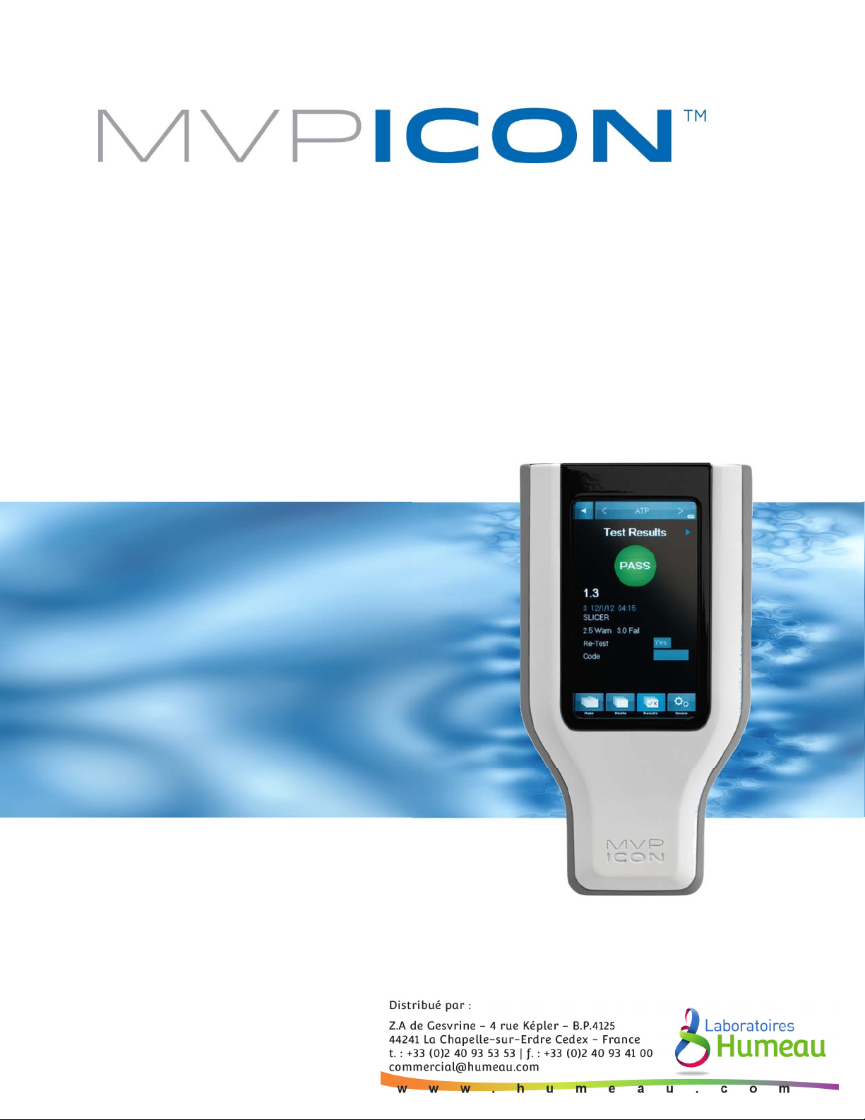
The LIGHTNING MVP ICON™ is a multi-parameter HACCP monitoring system to monitor key
quality indicators such as ATP, pH, temperature, conductivity, and concentration. The included
MVP ICON Dashboard software allows for easy trending and analysis of results. The software’s
dashboard provides an overview of key control metrics at a glance.
Below is a description of each of the parameters measured by the MVP ICON.
ATP
Adenosine triphosphate (ATP) is present in all living cells including food residues, bacteria, yeast
and molds. Testing for ATP is highly useful as an indicator of cleaning verification within a food
manufacturing facility. Detecting its presence indicates a surface or liquid contains organic
matter. If ATP is present, the potential exists for contamination of food or beverages coming into
contact with the surface or liquid containing ATP. Surfaces contaminated with ATP lead to issues
with product quality and pose a threat to public health.
pH
Monitoring the pH of foods is a vital step in producing a safe, quality product. Maintaining the
appropriate pH level is an important factor in food manufacturing as pH is often related to the
physical and chemical reactions that take place during production.
Temperature
Certain manufacturers produce foods that require the product to maintain a specific temperature
during the production process. Monitoring temperature prevents products from allowing certain
organisms to grow and thrive, therefore contaminating the product and leading to public health
and product quality issues.
Conductivity
Conductivity, measured in microSiemens (µS), is a material’s ability to conduct an electrical
current.
Concentration
Accurately measuring cleaner and sanitizer concentrations is a crucial element to protecting food
quality. Excessively high concentrations of chemicals are costly and can lead to the damage of
equipment, product, and potentially harm operators in contact with the solution. If a chemical’s
concentration is too low, it can allow for the potential growth of pathogenic organisms leading to
public health and product quality issues.
1
Page 8

Materials and Equipment
The LIGHTNING MVP ICON is a multi-parameter HACCP monitoring system. The MVP ICON
utilizes accessory probes and sampling devices to measure and record key HACCP parameters
including ATP, pH, temperature, conductivity, and concentration. The included MVP ICON
Dashboard software allows for easy trending and analysis of results. The software’s dashboard
provides an overview of key control metrics at a glance.
Included in the Box
• MVP ICON instrument
• MVP ICON Dashboard software CD
• USB cable
• AC adapter (US)
• International adapters
• Shoulder strap
ATP Supplies (Purchased Separately)
• LIGHTNING MVP ICON Surface Sampling Device - for detection of ATP on surfaces
• LIGHTNING MVP ICON Liquid Sampling Device - for detection of ATP in Clean in Place
(CIP) rinse water and other liquid samples
• LIGHTNING MVP ICON ATP Calibrator Set – for calibration and verification of the ICON
instrument for accurate detection of ATP
• LIGHTNING MVP ICON ATP Positive Control – a lyophilized, stable preparation of a known
concentration of ATP for routine verification of the ICON system’s performance
Conductivity and Concentration Supplies
• ICON Conductivity Probe - for measuring conductivity of liquids and determining
chemical concentration of sanitizers and cleaners
• Conductivity Standard (500 µs) – for calibration of ICON Conductivity Probe
pH Supplies
• ICON pH Probe – for measuring pH and temperature of solutions
• pH Calibration Standards (pH 4.00, pH 7.00, and pH 10.00) – for calibration of ICON pH
Probe
Temperature Supplies
• ICON Temperature Probe – for measuring product temperatures
Charging the MVP ICON
To charge the MVP ICON battery, use the provided adaptor and plug into a wall outlet. The
battery will take approximately 2 – 4 hours to fully charge to 100%.
Charging Best Practices
• Utilize the ICON until the instrument displays Code 11 – Low Battery, then charge to
100% via the wall outlet.
• Do not leave the ICON plugged into the wall outlet overnight. Doing so will overcharge
the battery and shorten its lifespan.
NOTE: The MVP ICON battery will not charge from a computer via a USB connection. This will
utilize more battery power, potentially draining the charge.
2
Page 9
MVP ICON at a Glance 1
Battery Indicator
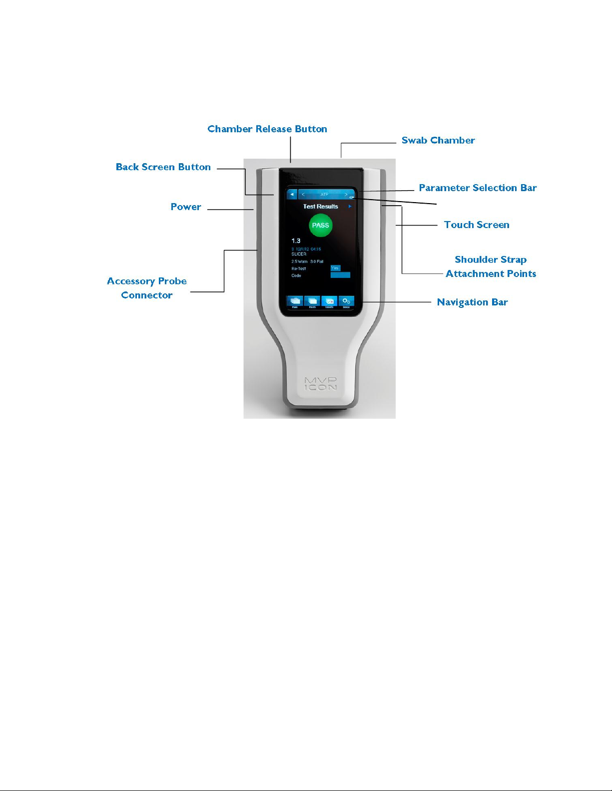
Instrument Overview
Home Screen and Navigation
The MVP ICON features a pressure-sensitive color touch screen display that can be operated
while wearing gloves and is suitable for use under all lighting conditions.
The home screen of the ICON lists pertinent statistics about the unit based on the parameter
selected, including:
• Number of test points, sample plans, and results stored on the instrument
• Available memory
• Serial number
• Date of last ATP calibration
• Last date of upload to ICON software
• Available battery charge
The parameter selection bar at the top of the screen is used to select the desired parameter
(ATP, pH, Temperature, Concentration, or Conductivity) for taking new readings or viewing
stored results.
3
Page 10
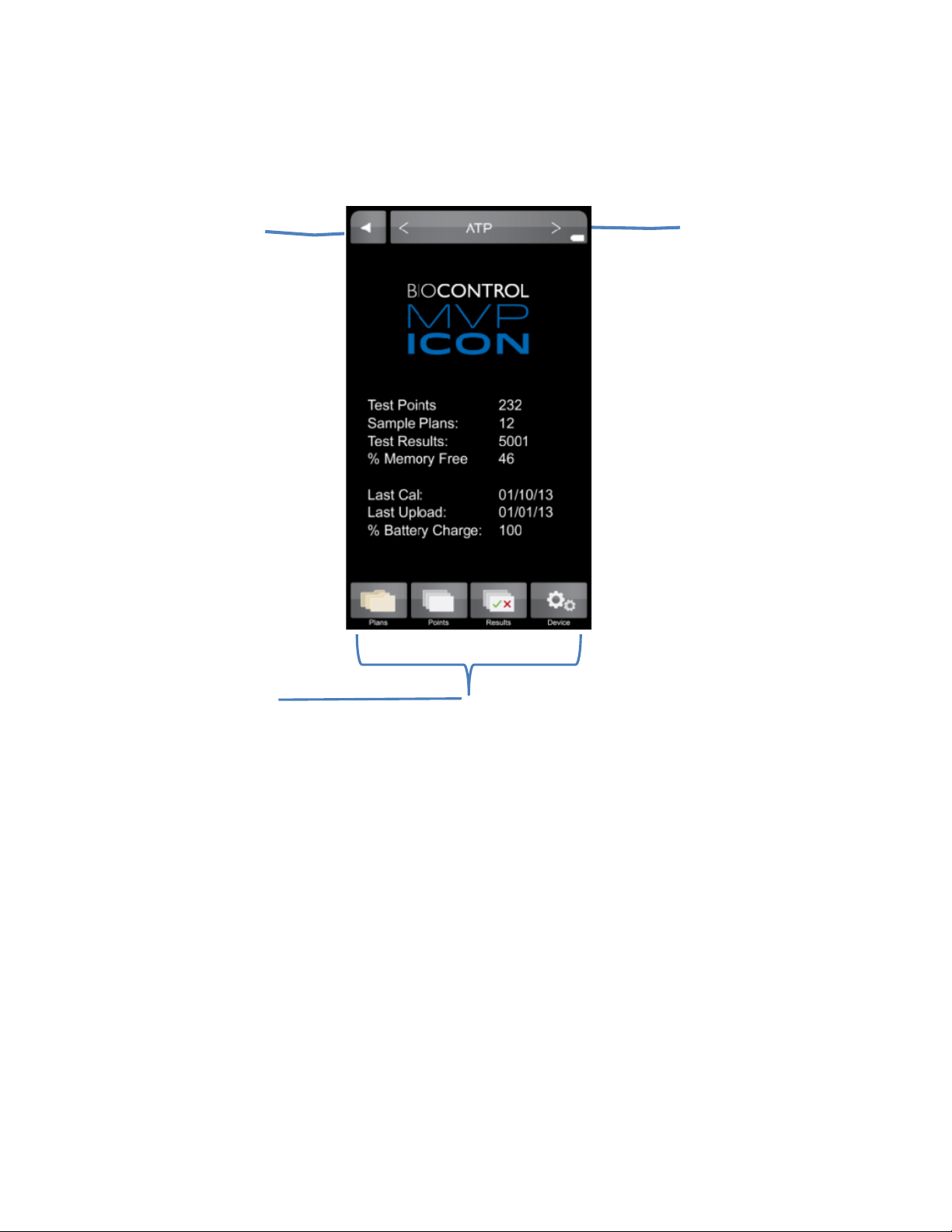
The buttons on the bottom of the screen are used to access the following functions:
Switch between
Move back
Access a list of sample plans,
change instrument settings
• Plans – allows the user to select a specific sample plan
• Points – allows the user to select a specific test point
• Results – provides a list of recorded results for each test point
• Device – provides access to the instrument specific settings including screen brightness,
volume, language, date and time, deleting results, and calibration
one screen
measurement
parameters
test points, results, or
To preserve battery life, the ICON screen will automatically dim after one minute of inactivity and
turn dark after two minutes. To awaken the instrument, simply touch the screen or power
button. After five minutes of inactivity the ICON will completely shut down (
See Chapter
customizing these settings).
C
alibrating the Touch Screen
It is recommended to calibrate the touch screen, should it freeze or become difficult to navigate.
Connect the MVP ICON to the Dashboard software.
• Select ICON Setup from the top toolbar menu
• Select “Calibrate Display”
• The ICON instrument will then enter its screen calibration mode
• Follow the prompts on the screen, ensuring to touch the tip of each arrow for the most
precise and accurate calibration.
Note: Calibrating the touch screen requires precisely touching specific areas of the screen. This
procedure should be performed using the blunt end of a pen, an ICON sampling device, or similar
stylus-like object.
Self-Diagnostic
When the ICON is powered on, the instrument will perform a 45-second self-diagnostic and
record a baseline reading. The chamber must be empty during the initial start-up procedure.
25 for
4
Page 11
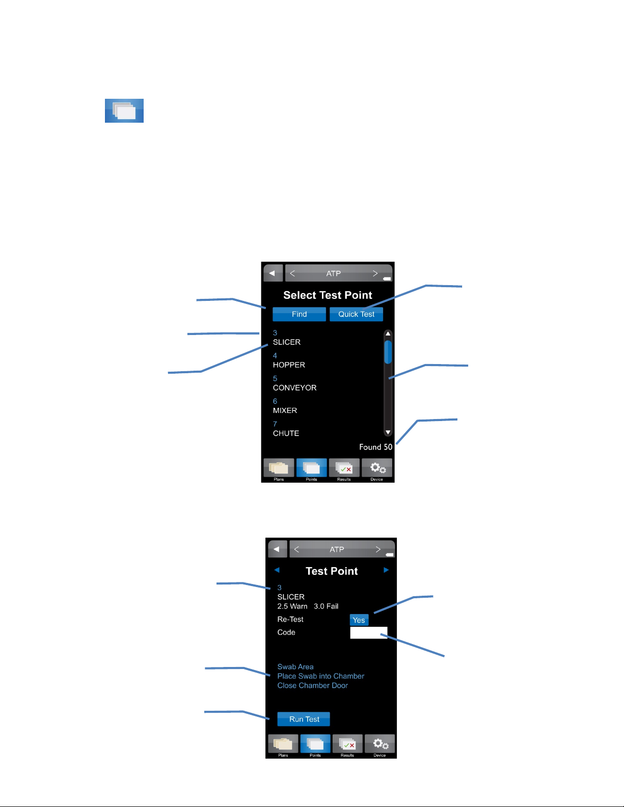
Quick Test
Test point name
Points 2
Points
The “Points” tab on the bottom menu of the ICON contains a list of all created test points in
numerical order, independent of sample plan assignment.
Selecting a Test Point
• Scroll through a list of test points in numeric order using the scroll bar on the right side of
the screen.
Search for a specific
test point
Test point number
Further details for each test point can be found by selecting the desired test point.
Test point number, name,
and Warn/Fail thresholds
Instructions for
inserting swab
Press to run
sample
5
See Chapter 8
Scroll Bar
Total number of test
points assigned
Re-Test
See Chapter 7
Code
See Chapter 9
Page 12
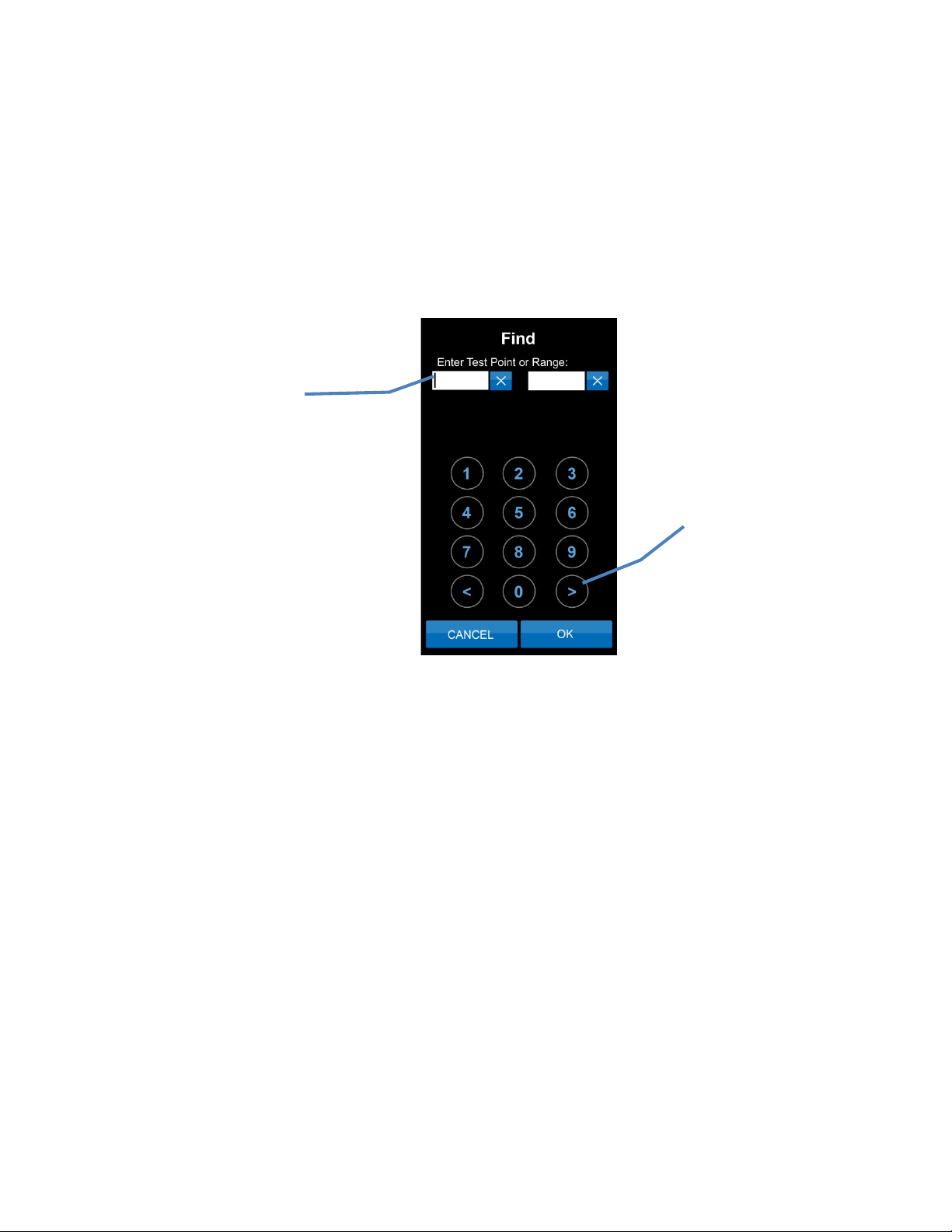
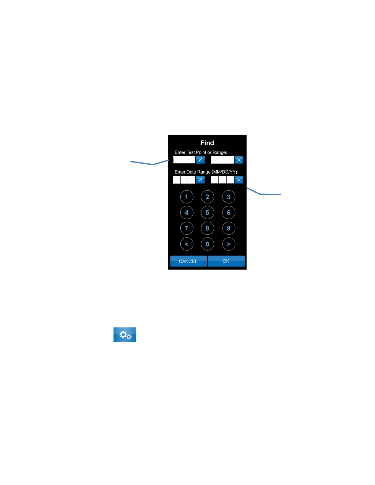
Finding a Test Point
If a test point (or range of test points) is not readily available on the instrument screen, the
“Find” feature within “Points” can be used to search for specific test points.
• To search for a range of test points enter the first and last test point number in the
range.
• To search for a single test point enter the test point number as the beginning of the
range and leave the end of the range blank.
Note: To clear a field entry, press the “X” next to the associated field.
• The < and > buttons on the bottom of the key pad will clear entries or tab to the next field.
Enter individual test
point number or range
Use these buttons to
clear entries or tab
to next field
6
Page 13
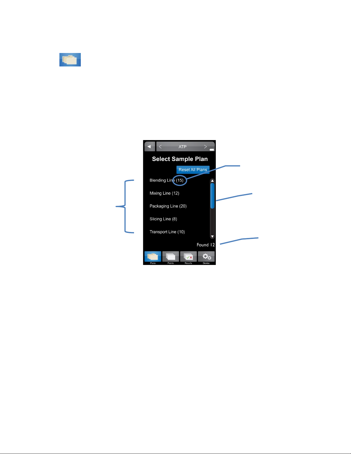
Plans 3
List of
Number of available
Number of test points assigned
Plans
To view a list of available sample plans for a desired parameter, select the “Plans” tab on the
bottom menu of the ICON instrument. Sample plans are a customized grouping of test points. A
sample plan can represent a group of test points in a particular production area, direct versus
indirect locations, or even a work shift or day of the week. Sample plans are listed by name and
include the number of assigned test points in each plan.
sample plans
Selecting a Sample Plan
• To select a particular sample plan, lightly press on the desired sample plan name.
• Once selected, a list of test points will be displayed in numeric order. Select desired test
point and proceed with taking a reading.
Sample Plan Tracker
The progress of testing within a sample plan is automatically tracked on the MVP ICON display.
Each time a test point is sampled within a plan, a correlating colored result appears next to the
test point. This visual indicator not only identifies which test point has been tested within the
plan, it also serves as identification for which test points require re-cleaning and re-testing (warns
and/or failed results). Once a point has been tested within an individual sample plan, a blue
rectangle appears next to the sample plan name on the main “Plans” menu.
The progress of multiple sample plans is automatically and simultaneously tracked. To clear the
progress of an individual sample plan, simply press “Reset Plan” from within the individual plan’s
display. To clear the progress of all tracked plans, press “Reset All Plans” from the main “Plans”
menu.
to sample plan
Scroll bar
sample plans
7
Page 14
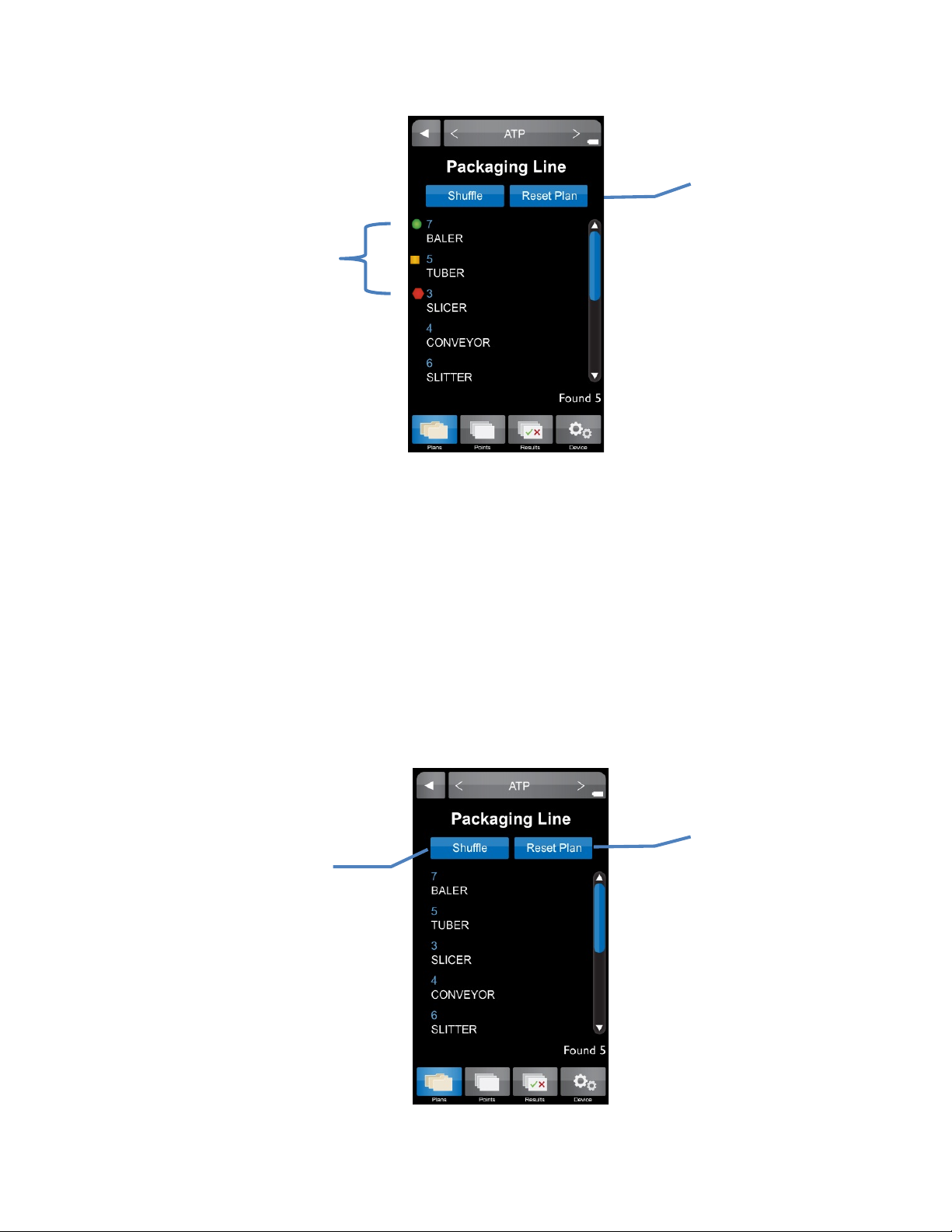
Press to shuffle
test points
Green indicates
Shuffle
The order of test points within a sample plan can be randomized or “shuffled.” This feature can
be used to ensure that all test points have an equal probability of being tested. To shuffle test
points:
a pass result,
yellow for warn,
red for fail
• Select the desired sample plan (as described above).
• Press the blue “Shuffle” button located above the test point list.
• Select first test point in newly shuffled list and proceed to taking test.
• To reset the test points in the plan back to numeric order, press the “Reset Plan” button
located next to “Shuffle”.
Press to clear the
tracker’s progress for
an individual plan
Press to restore test
points to original order
8
Page 15
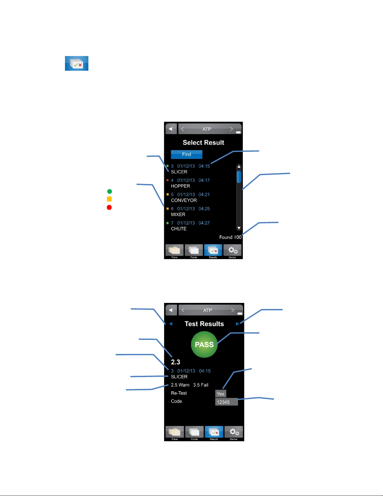
Test point name
Use scroll bar to move
through list of results
Visual indicator of result
Test point number,
Test point name
Test point thresholds
Re-test
See Chapter 7
Next test point
Previous test point
date, and time of result
Results 4
Results
To view a list of stored results for the desired parameter select the “Results” tab on the bottom
menu of the ICON instrument. Results are listed in numeric order by test point number and the
most recent result for each test point is displayed.
Further details for each result can be found by selecting the desired test point.
Pass
Warn
Fail
MVP ICON reading
Test point number, date
and time of result
Total number of
results found
Result
Code
See Chapter 9
9
Page 16
Finding Results
To search for a specific result or range of results touch the “Find” button at the top of the
“Results” screen.
• To search for a range of test points enter the first and last test point number in the
range.
• To search for a single test point enter the test point number as the beginning of the
range and leave the end of the range blank.
• To search for results from a specific date range enter the beginning and ending dates for
the range.
• To search for results from a specific day enter the desired date as the beginning of the
range and leave the ending date blank.
Search for individual
or range of test
points
Search for single
day or range of
dates
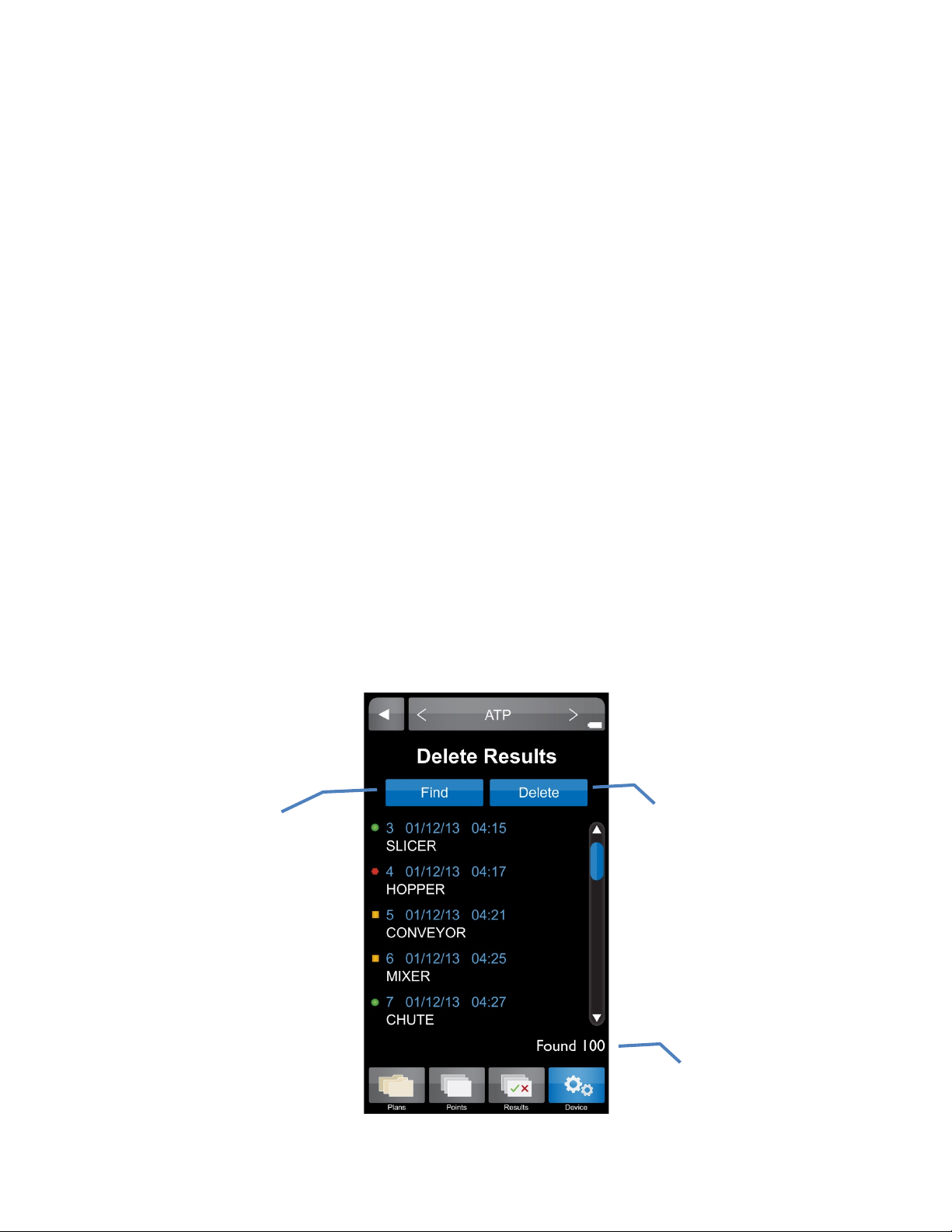
Deleting Results
Results can be deleted directly from the MVP ICON instrument using the delete function found in
the “Device” tab. (See Chapter
5 for more details)
10
Page 17
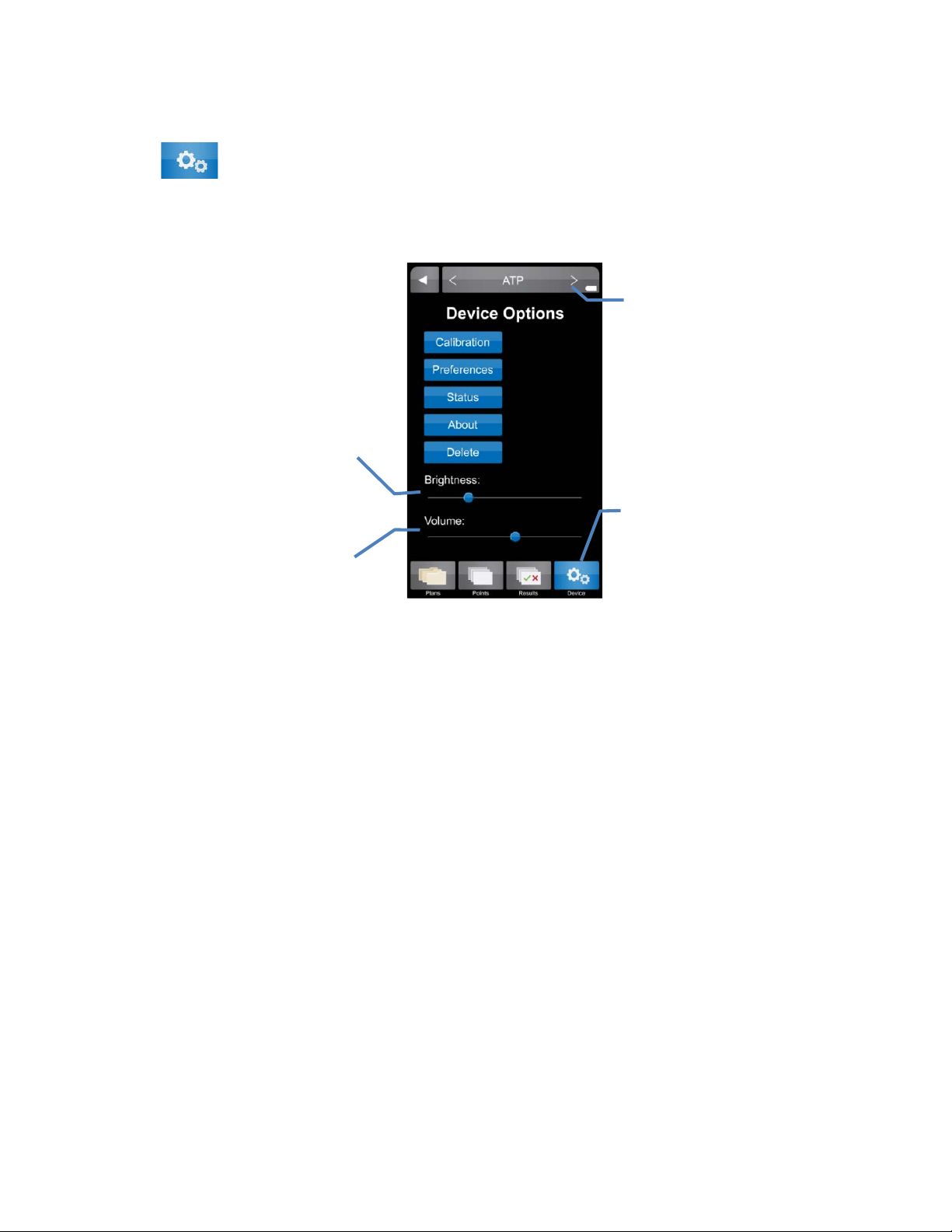
Device 5
Adjust display
brightness
Adjust audible
Device
Device settings for the ICON can be accessed by selecting the “Device” tab at the bottom of the
ICON screen.
alert volume
Calibration
Allows for calibration of the MVP ICON for the specific parameter selected (ATP, pH,
Temperature, Conductivity, or Concentration; See Chapter
11).
TP parameter includes procedures for system verification using LIGHTNING MVP ICON ATP
A
Positive Control and LIGHTNING MVP ICON Calibrator Set (see Chapter 11).
Preferences
Allows user to customize the language, date, time, temperature and RLU display
• Time – Time can be displayed in either a 12-hour (2:00 PM) or 24-hour format (14:00).
• Date – Date can be displayed as either Month/Day/Year or Day/Month/Year.
• Language – The following languages are available for the MVP ICON: English, French,
Spanish, German, and Portuguese.
• Show RLU – ATP results are displayed as Zones of Cleanliness; results can also be
displayed as Relative Light Units or RLU’s.
• Temperature – Temperature can be displayed as either °F or °C.
Status
Includes diagnostic information used to troubleshoot the instrument such as:
• Sample Chamber door status (open/closed)
• Charger status (battery/AC)
• Battery voltage
Change selected
parameter
Access Device
settings
11
Page 18
About
Displays instrument specific information:
• Serial number
• Hardware version
• Firmware version
Delete
Allows user to delete result for the selected parameter (optional password protection)
Results can be deleted as:
• Individual results
• A group of specific test points
• Results from a specific date range
To Delete a Result
• From the “Device” menu, select “Delete”. Ensure the device displays the desired
parameter.
• Search for result or range of results to delete in same manner as “Results” menu (
see
Chapter 4).
hen individual or range of results has been selected, press “Delete”.
• W
• A warning will appear to ensure user wishes to proceed.
• Select “Yes” to continue or “No” to return to previous screen.
• If “Yes” is selected the optional password screen will appear (if required).
• Enter correct password to delete results.
• The screen will validate results have been deleted.
Note: The ICON screen will freeze until results are deleted. A confirmation screen will indicate the
desired results were deleted.
Search for individual or
range of results
Press to delete results
Number of results
12
Page 19
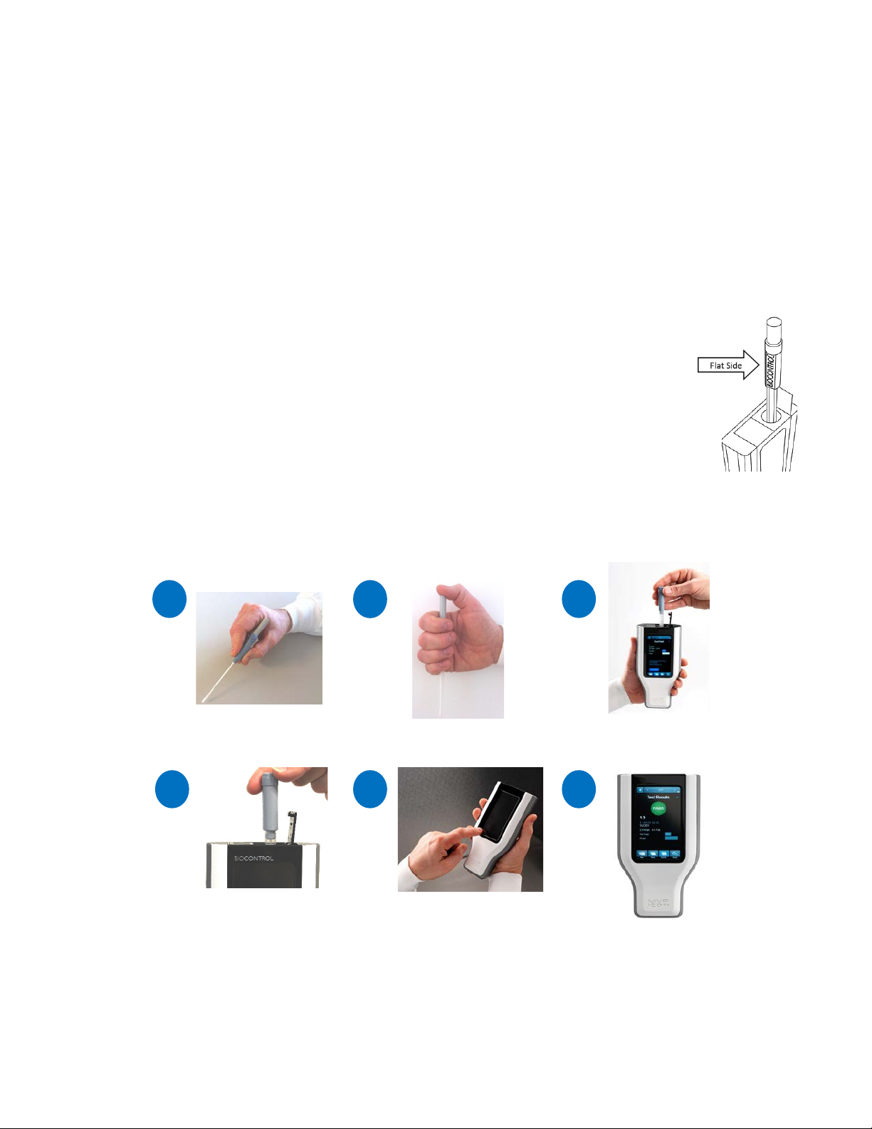
Taking a Reading 6
TAKING AN ATP READING
Swab surface
Activate swab
Insert activated
swab into ICON
Select test point or
quick test
Result displayed
1 2356
Figure 1
Insert swab with
left and right
4
ATP
• Select “ATP” mode in the top menu bar from any screen. Use < or > arrows to toggle
through modes.
• Select “Points” from the bottom icon menu
• Select desired test point or use the scroll bar to scroll through the list of available test
points.
Note: To locate a test point not currently displayed, please reference Chapter 2 – “Finding
a Test Point”.
• At the “Test Point” screen, designate if sample is a “Re-Test” (
• Enter an optional customized code (
see Chapter
9)
see Chapter
7).
• Follow the directions in blue to swab the area and insert the sampling device.
Note: When inserting a sampling device into the MVP ICON, ensure the flat
sides of the swab chamber face left to right. Do not force the sampling
device into the MVP ICON (see Figure 1).
• Press “Run Test”
• Screen will show “Test in Progress” with a countdown to completion.
Note: Please reference the Directions for Use included with the LIGHTNING
MVP ICON Surface or Liquid Sampling Devices for additional information.
two flat sides facing
13
Page 20

pH
Please reference the Directions for Use included with the ICON pH Probe for preparation of the
probe prior to use.
• Ensure the ICON pH Probe is properly connected to the side of the device (probe adapter
surface with arrows should face the back of ICON).
• Select “pH” mode in the top menu bar from any screen. Use < or > arrows to toggle
through modes.
• Select “Points” from the bottom icon menu.
• Select desired test point or use the scroll bar to scroll through the list of available test
points.
• Designate if the sample is a “Re-Test” (
• E
nter an optional customized code (see Chapter 9).
see Chapter
7).
• Follow the directions in blue for inserting probe into sample.
• Press “Run Test”.
Note: Squeeze sides of probe adapter to release and disconnect from ICON.
Temperature
Please reference the Directions for Use included with the ICON Temperature Probe for proper
technique and cleaning of the probe prior to use.
• Ensure the ICON Temperature Probe is properly connected to the side of the device
(probe adapter surface with arrows should face the back of ICON).
• Select “Temperature” mode in the top menu bar from any screen. Use < or > arrows to
toggle through modes.
• Select “Points” from the bottom icon menu.
• Select desired test point or use the scroll bar to scroll through the list of available test
points.
• Designate if the sample is a “Re-Test” (
see Chapter
7).
• Enter an optional customized code (see Chapter 9).
• Follow the directions in blue for inserting probe into sample
• Press “Run Test”.
Note: Squeeze sides of probe adapter to release and disconnect from ICON.
Conductivity
Please reference the Directions for Use included with the ICON Conductivity Probe for
preparation of the probe prior to use.
• Ensure the ICON Conductivity Probe is properly connected to the side of the device
(probe adapter surface with arrows should face the back of ICON).
• Select “Conductivity” mode in the top menu bar from any screen. Use < or > arrows to
toggle through modes.
• Select “Points” from the bottom icon menu.
• Select desired test point or use the scroll bar to scroll through the list of available test
points.
• Designate if the sample is a “Re-Test” (see Chapter 7).
nter an optional customized code (see Chapter 9).
• E
• Follow the directions in blue for inserting probe into sample.
• Press “Run Test”.
Note: Squeeze sides of probe adapter to release and disconnect from ICON.
14
Page 21

Concentration
Please reference the Directions for Use included with the ICON Conductivity Probe for
preparation of the probe prior to use.
Before Taking a Concentration (ppm) Reading
Prior to taking a Concentration reading (ppm), it is important to ensure the chemical standard
assigned to each test point has been properly calibrated. Please see Chapter
11 – Calibration for
instructions on calibrating the chemical standard.
N
ote: A Concentration test point cannot be tested unless the chemical standard has been
calibrated and saved prior to taking the reading.
Taking a Concentration Reading
• Ensure the ICON Conductivity probe is properly connected to the side of the device
(probe adapter surface with arrows should face the back of ICON).
• Select “Concentration” mode in the top menu bar from any screen. Use < or > arrows to
toggle through modes.
• Select “Points” from the bottom menu.
• Select desired test point or use the scroll bar to scroll through the list of available test
points.
• Designate if the sample is a “Re-Test” (
nter an optional customized code (see Chapter 9).
• E
see Chapter
7).
• Follow the directions in blue for inserting probe into sample.
• Press “Run Test”.
Note: Squeeze sides of probe adapter to release and disconnect from ICON.
Note: The “Test Source Water” button, located next to “Run Test,” allows for source water to be
tested with each sample, should it vary from the source water used to prepare the calibrated
chemical standard. If the source water is similar to the chemical standard, it is not necessary to
the test the source water with each sample.
15
Page 22
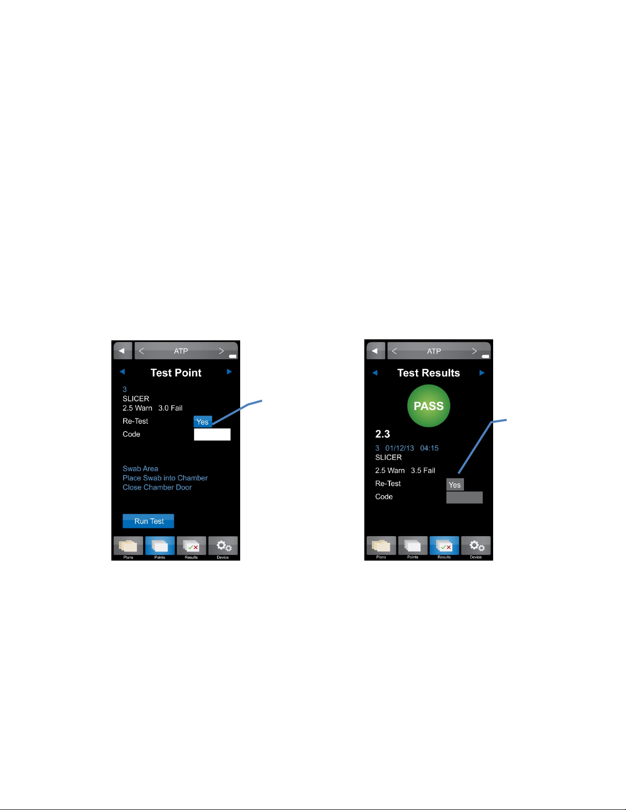
Re-Test Function 7
Prior to Reading Sample
After Sample is Measured
Press to mark
or “No”
Press to mark
or “No”
Re-Tests
A test result for any of the MVP ICON parameters can be coded as a “re-test.” When testing for
ATP, areas that show high ATP readings should be re-cleaned and re-tested to verify adequate
cleaning. A test point can be coded as a re-test either at the time the sample was taken or at the
results screen.
How to Re-Test a Sample
• Select the desired test point through the “Points” or “Plans” menu options. Please refer
to Chapter 6 for taking an initial reading.
• To designate the test point is a re-test before the sample is measured, press the blue
button next to “Re-Test” until “Yes” appears.
• To indicate a re-test after the sample was taken, press the button next to “Re-Test” at
the “Test Results” screen.
re-test as “Yes”
re-test as “Yes”
16
Page 23

Quick Test Function 8
Quick Tests
The Quick Test function on the ICON allows for a test measurement to be taken without saving
the results to a test point. This can be useful for training or other instances where saving test
results is not needed. However, users have the option of saving results and converting to
assigned test points once the data is updated to the ICON Dashboard software.
See Chapter
Test feature and convert into an assigned test point.
T
ake a Quick Test
• Select “Points” from the lower ICON menu.
• At the “Select Test Point” screen, press the “Quick Test” button at top in blue.
• Enter Quick Test password, if applicable.
• At the “Test Point” screen, the Quick Test can be coded as a “Re-Test” with optional
• Follow screen directions to swab area and insert swab in chamber.
• Press “Run Test”.
• Press “Save” to save Quick Test results onto the unit or “Discard” to return to the prior
Locate a Quick Test Result on the ICON
The newly saved Quick Test result can now be located under “Results” from the lower ICON
menu in three different ways:
• Scroll to the bottom of the results menu.
• Select “Find” and enter test point or test point range.
• Select “Find” and enter date or date range.
22 – ICON Instrument Setup for instructions on how to password protect the Quick
Note: Quick Test can only be taken from the “Points” menu and is applicable for all
parameters.
Note: If a Quick Test password was not enforced via the ICON Software, user will be
guided directly to “Test Point” screen.
customized code (
N
ote: Quick Test can also be labeled as a re-test after the sample has been measured.
screen.
see Chapters
7 and 9, respectively).
17
Page 24
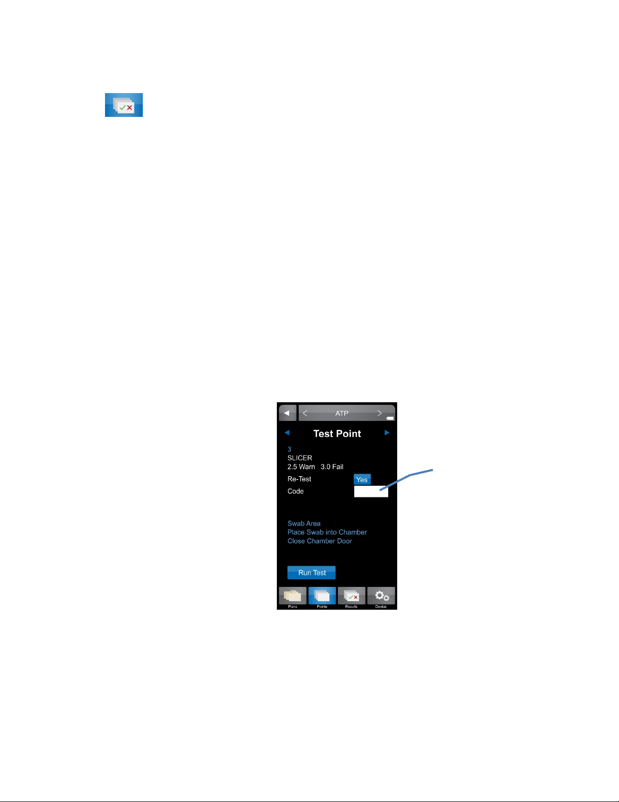
Code Field 9
Enter a customized
Code Field
The “Code” field on the ICON is a place to enter additional identifying information about an
assigned test point into the instrument at the time of testing. For example, a numeric code could
be entered prior to taking a sample to identify a particular sanitation worker, product, or location
within the facility not previously identified during test point setup in the software. The code field
on the ICON is a numeric value only. Any meaning correlating to this code should be documented
separately for reference.
Entering a Code
Codes are entered after a test point has been selected, either through “Points” or “Plans” and
must be entered prior to measuring the sample.
• Select desired test point via “Points” or “Plans”.
• At the “Test Point” screen, locate the “Code” field and lightly press the white box .
• Enter the desired code, up to 4 digits.
Note: This field is not password protected. Any 1 – 4 digit code can be entered on this
screen.
• The code will now be populated in the “Code” field and will be associated with that
particular result.
Viewing a Coded Result
• Any test point with an assigned code can be viewed in the “Results” section of the ICON
menu.
• Coded results are also available in “Raw Data” within the ICON Software, once uploaded
(see Chapter
20 – Raw Data for more information).
code here
18
Page 25
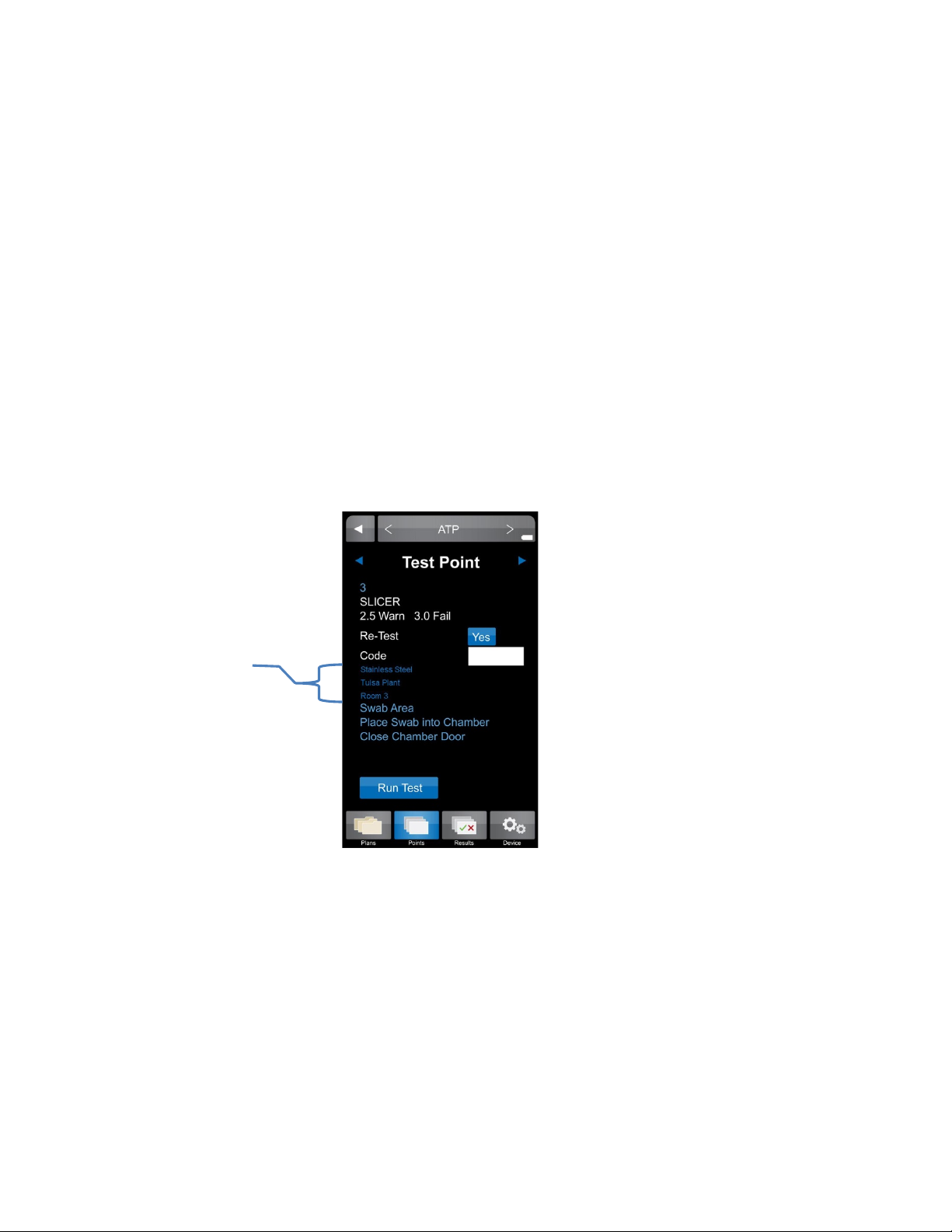
Custom Fields 10
Custom Fields
“Custom Fields” present another opportunity to enter customized information about test points
and are established within the ICON Software. The three custom fields can be populated with
information such as a test point’s associated product, location within the facility (ex. Room 3),
and the type of surface being sampled (ex. Stainless Steel).
Please see Chapter 15 – Creating Test Points for more information on setting up “Custom Fields”
within the ICON Software.
iewing Custom Fields on the ICON
V
• Select desired test point via “Points” or “Plans”.
• All custom field entries for the assigned test point will be displayed directly below the
• Custom field designations are also available in “Raw Data” within the ICON Software,
Custom
Field
entries
“Code” field prior to measuring the sample.
once uploaded.
19
Page 26

Calibration / Verification 11
Calibration
The MVP ICON’s parameters can be manually calibrated on-site to ensure the instrument is
working at its optimal performance. In addition, the ATP calibration function also features
“Verification” which records and stores the positive and negative control readings for both the
sampling device and calibrator set.
ATP
The MVP ICON is calibrated at the factory; however, users should also calibrate the ICON prior to
first use. It is also recommended to run positive control verifications every other day and
calibrate when necessary. The calibration rods last for five years. The ICON is calibrated for ATP
using a standardized two-point calibration procedure. This function requires the LIGHTNING MVP
ICON Calibrator Set which includes the necessary luminescent and non-luminescent calibrators to
perform the operation.
To insert the calibration rod into the MVP ICON, hold the calibrator by the wider end with two
flat sides and insert the opposite end into the ICON. Ensure the flat sides of the calibrator’s base
chamber are facing left to right.
Calibration
• Ensure the device is in ATP mode.
• Select “Device” from the ICON’s lower menu.
• From the “Device Options” screen select “Calibration”; press “Calibrate”.
• Enter the Reference Value (found on the luminescent calibrator’s label).
• “Insert Luminescent Calibrator” and close the chamber door; press “Calibrate”.
• Remove luminescent calibrator, insert non-luminescent calibrator, close door and press
An error message will be displayed if results are not within the ICON’s specification. Typical
causes for failed calibration include: readings too high or low for the luminescent or nonluminescent calibrators, light leaks within the chamber, or a build-up of static. Refer to the
calibrator’s Directions for Use for additional information. For assistance, contact BioControl
Technical Support at 800.245.0113.
If successful, the date of calibration will appear on the ICON’s home screen and the record will
upload into the software database upon the next synchronization between the instrument and
software.
System or Swab Performance Verification
Verification is designed to ensure the instrument and swabs are working correctly. The
LIGHTNING MVP ICON ATP Positive Control provides a sample which produces a positive ATP
result when assayed with the MVP ICON system. It is recommended to run ATP Positive Controls
every other day and incorporate results into an overall Quality Control program.
Positive Control Procedure
Requires ATP Positive Controls
• Ensure instrument is in ATP mode.
• Select “Device” from the ICON’s lower menu.
“Calibrate”.
20
Page 27

• From “Device” screen select “Calibration”.
• Press the “Positive Control” button under the “Verification” menu in ATP Calibration
mode.
• Open the ATP Positive Control vial.
• Insert a LIGHTNING MVP ICON Surface Sampling Device and completely dissolve the
positive control pellet onto the tip of the swab.
Note: Take care to ensure the swab tip does not touch any surface other than the inside
of the vial.
• Activate the swab, insert into the chamber with swab chamber facing left to right, and
close the chamber door.
• Press “Verify” to run the verification.
The result for a positive control should read between 3.1 – 4.3 Zones.
• Results greater than 4.3 indicate a potential contamination of either the swab or positive
control. Re-test in duplicate and average the two results.
• Between 2.6 – 3.0 Zones, more thorough swabbing of the vial may be required.
• Below 2.6 Zones, ensure the device was properly activated. If device was activated
properly, it may indicate a problem with the instrument, device, or positive controls.
Repeat the test with a new vial of positive control and new sampling device.
• If verification fails again, calibrate the instrument and repeat verification with a new vial
of positive control and sampling device.
• If still out of range, contact BioControl Technical Support at 800.245.0113.
Negative Control Procedure
A negative control is an unused but activated swab.
• Press the “Negative Control” button under the Verification menu in ATP Calibration.
• Activate the swab, insert into the chamber with the swab chamber facing left to right,
and close the chamber door.
• Press “Verify” to run the verification.
The result for a negative swab should read between 1.0 – 2.5 Zones.
LIGHTNING MVP ICON Instrument Verification
To verify if the instrument is reading correctly, the luminescent and non-luminescent calibrators
are used.
The luminescent calibrator consists of a
14
C radioactive source which emits a very low level (5x10⁵
d.p.m. or 0.225 microcuries) of low-energy β radiation in a plastic scintillating matrix. This matrix
is configured to provide a constant light output at a sufficiently high level in order to perform
consistent verification and calibration over the shelf-life of the calibrator.
The non-luminescent calibrator provides a reliable low-end or “dark” source reading.
Luminescent Calibrator Procedure
• Under the “Verification” menu in ATP Calibration, select “Luminescent Calibrator”.
• Insert the luminescent calibrator and close the chamber door.
• Press “Verify”.
In a properly calibrated MVP ICON, the calibrator should read within 0.1 Zones of the zone value
displayed on the calibrator’s label.
21
Page 28

Non-Luminescent Calibrator Procedure
• Under the “Verification” menu in ATP Calibration, select “Non-Luminescent Calibrator”.
• Insert the non-luminescent calibrator and close the chamber door.
• Press “Verify”.
The non-luminescent calibrator should read 1.0 – 1.5 Zones. Readings outside this range can
indicate problems with the instrument. If the verification fails, calibrate the ICON. If the
calibration fails, contact BioControl technical Support.
pH
The pH calibration process uses three standard buffers (pH 4.00, 7.00, and 10.00). This threepoint calibration allows for the probe to be used across the entire pH range. For optimal
accuracy, the ICON pH probe should be calibrated before first use, at the beginning of each day
and when changing test materials.
Calibration Procedure
Prior to performing calibration, rinse the pH probe with deionized or distilled water. Soak in pH
7.00 buffer for at least 10 minutes prior to calibration and ensure the standard is mixed well.
• Connect the pH probe to the instrument, ensuring arrows on the adaptor face the back
of the instrument.
• Verify the ICON is in pH mode.
• Select “Device” from the ICON’s lower menu.
• Insert the probe into the 7.00 standard solution and press “Calibrate”.
• When prompted, insert the probe into the 10.00 standard solution and press “Calibrate”.
• When prompted, insert the probe into the 4.00 standard solution and press “Calibrate”.
Note: If the probe will not calibrate, it usually indicates a failing probe or contaminated buffers.
Be sure to keep buffers sealed when not in use. Do not use expired buffers.
Temperature
The ICON Temperature probe is calibrated using a single-point calibration process. Any known
temperature within operating range may be selected for calibration. Calibration is most accurate
when a temperature point close to the sample temperature is selected.
Calibration Procedure
• Connect the Temperature probe to the instrument, ensuring arrows on the adaptor face
the back of the instrument.
• Verify the ICON is in Temperature mode.
• Select “Device” from the ICON’s lower menu.
• Select “Calibration”.
• Enter the Reference Value (instrument will indicate either ˚F or ˚C based on settings).
• Insert probe into the reference sample of a known temperature entered above.
• Press “Calibrate”.
Conductivity
The ICON Conductivity probe reads in microSiemens (µS) for conductivity and requires the use of
a conductivity standard close to the target reading. The average conductivity standard in North
America is 500 µS. Rinse the Conductivity probe with deionized or distilled water and soak the
probe in the conductivity standard for at least two minutes prior to calibration.
22
Page 29

Calibration Procedure
• Connect the Conductivity probe to the instrument, ensuring arrows on the adaptor face
the back of the instrument.
• Verify the ICON is in Conductivity mode.
• Select “Device” from the ICON’s lower menu.
• Enter the Reference Value in microSiemens (µS).
• Insert the probe into the sample.
• Press “Calibrate”.
If the ICON is unable to calibrate the Conductivity probe, it is usually due to contamination or
otherwise incorrect standards or buffers. Ensure the standard is well-mixed and try the
calibration again. If unable to calibrate, contact BioControl Technical Support at 800.245.0113.
Concentration
To calibrate the Conductivity probe for measuring the concentration of specific
cleaning/sanitizing chemicals the probe must first be calibrated for conductivity as directed in the
preceding section – see Conductivity Calibration Procedure.
Next, a chemical standard must be prepared for each specific cleaning/sanitizing chemical to be
tested. The chemical standard is prepared by carefully mixing the chemical with the available
source water at the precise concentration for its intended use, per the manufacturer’s directions
(i.e. 200 ppm).
A corresponding chemical standard must also be created in the MVP ICON Dashboard software
and transferred to the ICON before the calibration procedure can be performed (
See Ch
apter
15).
alibration Procedure
C
• Connect the Conductivity probe to the instrument, ensuring arrows face the back of the
instrument.
• Verify the ICON is in Concentration mode.
• Select “Device” from the ICON’s lower menu.
• Select the desired standard.
• Insert the probe into the source water and press “Calibrate”.
• Insert the probe into the chemical standard and press “Calibrate”.
Note: The probe should be rinsed with deionized water between reading the source water and
chemical standard.
If the calibration is unsuccessful, remix the sanitizer or cleaner and try to calibrate again. If
unable to calibrate, please contact BioControl Technical Support at 800.245.0113.
The calibration procedure should be repeated whenever
• A new lot of sanitizer is to be used.
• A new vendor of sanitizer is used.
• The same sanitizer is used at a different ppm concentration.
23
Page 30

MVP ICON Dashboard Software at a Glance 12
Introduction
The innovative dashboard on the software’s home screen provides a quick overview of key
metrics and allows for immediate, corrective action. Detailed analysis reports provide
comprehensive data to identify hot-spots within the facility, track and trend data, and generate
audit-ready HACCP reports.
System Requirements
Windows XP, Vista, Windows 7, or Windows 8
Minimum memory requirement 512 MB; recommend at least 1GB or more of RAM
At least 16 GB of hard disk space
WXGA video resolution of 1280 x 800 or better
Mouse or other pointing device
One available USB port
CD Drive
Printer (optional)
Adobe PDF to print (optional)
24
Page 31

Installation 13
Installing the MVP ICON Dashboard Software
The MVP ICON Dashboard Software is included with the MVP ICON system and is loaded onto a
CD for installation. It is also available on the BioControl Web site at www.biocontrolsys.com
Contact BioControl Technical Support for more information on downloading software.
Note: Ensure the computer is assigned administrative rights prior to installation.
Installing the software:
• Insert software disc into computer CD drive.
• Follow the Install Wizard prompts by clicking “Next”.
• Connect ICON to computer, when prompted for driver installation.
• Click “Finish” to complete installation and install the desktop icon.
• Launch program from the desktop icon.
Note: When installing virtually on multiple user’s desktop, be sure to copy and paste the
installation folder onto each desktop and perform installation from hereby checking the
“setup.exe” file.
USB Driver Installation for Vista
Vista operating systems may require additional steps when installing USB drivers for the MVP
ICON Dashboard software. The software and drivers are included on the software installation CD
and can also be found on the BioControl Web site at www.biocontrolsys.com
their Customer IKD to log in.
Please follow the steps below for installing USB drivers on Vista operating systems.
• Insert the MVP ICON Dashboard software CD and follow the installation prompts. When
the driver installation prompt appears, select OK.”
• The software will continue its installation process, however, the following message may
appear, “MVP ICON driver did not install correctly. Follow any pending prompts to locate
the driver or review the manual for guidance.” If this message occurs, press “OK.”
• Turn on the MVP ICON instrument and plug into the computer’s USB port. At the “Found
New Hardware” message select, “Locate and install driver software.” Follow the prompts
to locate the driver from the software CD.
If the installation CD is not available, select, “I don’t have the disc, show me other options” and
browse to C: Program Files. Select the “BioControl Systems, Inc.” folder, then select the “Driver”
folder and click “Next” when prompted.
• A pop-up message will appear, “Would you like to install this device software?” Select
“Install.”
• The driver installation process will finish and the associated communications port will be
displayed.
For additional assistance, please contact BioControl Technical Support at 800.2456.0113.
. Users will need
.
25
Page 32

Dashboard 14
Example of ICON Software Dashboard
What is the ICON Dashboard?
The MVP ICON Dashboard software’s home screen displays a dashboard which provides an
overview of key program control metrics at-a-glance. This unique feature provides quality
assurance managers with an overall picture of the behavior and health of their HACCP and
hygiene program by highlighting where potential problems reside within the facility, or with the
execution of the program, to guide corrective action for immediate resolution. The dashboard
can be accessed from any screen in the software by clicking at the top of the screen.
26
Page 33

ATP Swabs to Target Widget
Allows users to set a target for the number of ATP swabs used and measure active usage against
this target. This data provides a quick assessment if the correct amount of swabs are being used,
indicating sufficient testing is taking place, or if testing needs to increase to ensure the plan is on
track.
The reading is based on the total amount of ATP test results uploaded to the ICON software
compared to the defined target quality goal for a given period.
• For example, if the target number of swabs is 200 per month and the ICON software
contains 50 test results for that time period, the ATP Swabs to Target percentage is 25%.
• Quick-test results are not included in the total ATP test results unless they are
subsequently saved and converted.
Setting ATP Swab Target
• Select the dropdown arrow at the top corner of the “% ATP Swabs to Target” widget.
• Select target frequency (Weekly, Monthly, Quarterly, Annually).
• Enter the target number of swabs based on the time period (ex. 300 per month, 75 per
week, etc.).
• Select “OK”.
When the target and frequency are indicated, the percentage of swabs used will automatically
update based on the total amount of results uploaded to the software.
ATP Re-Tests Widget
Defines how many test points have been coded as a re-test over a period of time. Re-tests are
commonly performed if a test point has produced a warn and/or fail result, therefore, the higher
the percentage of re-tests, the more often a test point has been re-cleaned and re-tested. Results
can be viewed Weekly, Monthly, Quarterly, or Annually.
Setting ATP Re-Test Target
• Select the dropdown arrow at the top corner of the “% ATP Re-Test” widget.
• Select the desired frequency (Weekly, Monthly, Quarterly, Annually).
• Check “Warnings Included” if your program requires all “warn” results to be re-cleaned
and re-tested.
• Select “OK”.
Note: It is critical before testing with the MVP ICON to determine if only failed results will be retested or if results with both a fail and warn reading will be re-tested, per your standard
operating procedures. This impacts how the re-test data is displayed in the graph.
27
Page 34

Next Calibration Widget
The “Next Calibration” feature alerts the user to the next required date of calibration for the
ICON instrument, based on their HACCP and hygiene monitoring program. Each time an
instrument is connected to the software, the “Next Calibration” feature will identify the unit by
its serial number and will reflect the next required date of calibration. If multiple units are synced
to a database, the software will reflect the unit that is due next for calibration.
This application helps comply with HACCP programs to ensure all instruments are calibrated on a
timely basis and is a useful tool for audits.
The due date is color-coded to reflect calibration urgency.
• Green indicates the instrument is within 80 percent of its next calibration due date.
• Yellow warns the user they are within 90 percent of their due date.
• Red indicates the unit is beyond its calibration due date.
Setting the Calibration Frequency Target
• Select the dropdown arrow at the top corner of the “Next Calibration” widget.
• Select the desired calibration frequency (Weekly, Monthly, Quarterly, Annually).
• Select “OK”.
Device Exclusion List
To exclude an inactive ICON from appearing in the Next Calibration widget:
• Select the dropdown arrow at the top corner of the “Next Calibration” widget.
• Press the “Device Exclusion List” button.
• Check the box next to the serial number of the desired ICON. The excluded serial number
no longer factors into the Next Calibration rotation.
Note: To allow the ICON to be placed back into rotation, simply uncheck the box next to the
desired serial number.
28
Page 35

Percentage each test
Percentage each test
Listed from lowest
greatest
ATP Fail Rate Graph
The first of the three graphs at the bottom of the dashboard is “ATP Fail Rate.” This graph guides
the quality team to problematic areas in the facility requiring prompt attention for immediate
resolution.
Results are ordered from test points with the highest percentage of failed ATP results to lowest.
Test point numbers
point failed
ATP Re-Test Rate Graph
The middle graph on the dashboard displays the “ATP Re-Test Rate” by test point. This graph
illustrates the percentage of times a test point was re-cleaned and re-tested over a designated
period to highlight potential problem areas needing more thorough cleaning. In addition, QA
Managers can verify if the sanitation protocol for re-cleaning failed test points is adequately
followed.
Note: It is critical before testing with the MVP ICON to determine if only failed results will be retested or if results with both a fail and warn reading will be re-tested, per your standard
operating procedures. This impacts how the re-test data is displayed in the graph.
Test point numbers
point was re-tested
percentage re-test to
29
Page 36

ATP Pass/Warn/Fail Rate Graph
Combined percentage total
Test Point Numbers
= % Warn results
= % Pass results
= % Fail results
Key:
This stacked column graph presents the percentage of pass, warn, and fail results for all selected
test points over a period of time. This graph directs the sanitation crew to areas in the facility
requiring special attention identifying those test points that have higher warn and fail rates.
Customizing Dashboard Graphs
• Select the dropdown arrow at the top corner of the appropriate graph.
• Select by test point (individual, range, or all) or by all test points assigned to a particular
sample plan.
• Select time period by Daily, Weekly, Monthly, Quarterly or Annually by max date range.
• Select “OK” to run the report.
of pass/warn/fail results for
each test point
30
Page 37

Creating Test Points 15
Test Point Setup Screen - ATP
About Creating Test Points
The MVP ICON Dashboard software allows for a wide range of test point setup and customization
options to ensure each unique area in the facility is identified by all necessary and applicable
information.
The ICON software also provides the ability to create sample plans to which a test point (or
multiple test points) can be assigned. Sample plans are a helpful way to organize a subset of test
points within a facility for better identification and to guide the sanitation crew during testing.
The MVP Collection feature allows for test points from multiple parameters (ATP, pH,
Conductivity, etc.) to be grouped together in order to analyze and view data as an interrelated
set to establish trends not previously identified.
ATP Test Points
Note: Test point assignments are alphanumeric and can be up to 25 characters long, however, the
ICON instrument will only display up to 15 characters of the name.
Note: The Warn/Fail threshold limits will automatically populate 2.5 for Warn and 3.0 for Fail,
based on the Zones of Cleanliness. Thresholds can be customized to any zone value between 1.3
and 5.0.
To change the threshold, simply click on the desired cell and change to the applicable correlating
threshold.
Create a new
test point
• From the software’s top menu, select “Test Point Setup”.
• From the table menu, ensure the ATP Test Point tab is highlighted in blue.
• From the left-hand column menu, select “New Test Point”.
Test points will be created in numerical order.
• Click on the “Name” column cell for the applicable test point to assign a name.
• If the reading is less than the Warn limit, the test point result will be reported as a pass.
• If the limit is greater than or equal to the Warn limit but less than the Fail threshold, the
result is a warn.
• If the reading is greater than or equal to the Fail limit, the test point result will be
reported as a fail.
Click cell to name
test point
Can adjust
Warn/Fail
thresholds
31
Page 38

Temperature
pH
Conductivity
pH Test Points
• Select “pH” from table menu.
• Select “New Test Point”.
• Click on the “Name” column cell for the applicable test point to assign a name.
Note: Test point assignments are alphanumeric and can be up to 25 characters long,
however, the ICON instrument will only display up to 15 characters of the name.
• Establish Low and High threshold limits for the test point (ex. Low = 3.80, High = 12.70).
• If a coinciding temperature measurement is desired, check the “Temp” box and set Temp
Low and Temp High limits.
NOTE: If the reading is below the Low limit or above the High limit, the test point will be reported
as a fail.
pH Low/High
thresholds
Check “Temp” box if
correlating temperature
reading desired
Temperature
Low/High thresholds
Temperature Test Points
• Select “Temperature” from the table menu.
• Select “New Test Point”.
• Click on the “Name” column cell for the applicable test point to assign a name.
Note: Test point assignments are alphanumeric and can be up to 25 characters long,
however, the ICON instrument will only display up to 15 characters of the name.
• Set Low and High threshold limits.
Note: Readings below the Low limit or above the High limit will result as a fail.
Conductivity Test Points
• Select “Conductivity” from the table menu.
• Click “New Test Point” to create a new Conductivity (µS) test point.
• Click on the “Name” column cell for the applicable test point to assign a name.
Note: Test point assignments are alphanumeric and can be up to 25 characters long,
however, the ICON instrument will only display up to 15 characters of the name.
• Establish Low and High threshold limits for the test point (ex. Low = 190, High = 401).
• If a coinciding temperature measurement is desired, check the “Temp” box and set Temp
Low and Temp High limits.
Note: If the reading falls below the Low limit or above the High limit, the test point result is
reported as a fail.
32
Page 39

Low/High
Concentration
Chemical Sta ndard
Chemical Standards
Concentration test points require an associated chemical standard at a designated working
concentration (ex. Quat 200 ppm). In order to assign a chemical standard to a Concentration test
point, one must first be created under the “Chemical Standards” tab.
• Select “Chemical Standard” from the table menu.
• Click “New Test Point” to create a new chemical standard.
• Assign a chemical standard name under the “Name” column (i.e. brand name of the
chemical).
• Under “PPM” enter the designated working strength of the chemical (ex. 200).
• The newly created chemical standard will now be an available drop-down selection under
“Standards” in Concentration Test Points.
Strength in partper-million
Concentration Test Points
• Select “Concentration” from the table menu.
• Click “New Test Point” to create a new Concentration (PPM) test point.
• Click on the “Name” column cell for the applicable test point to assign a name.
Note: Test point assignments are alphanumeric and can be up to 25 characters long,
however, the ICON instrument will only display up to 15 characters of the name.
• Establish Low and High threshold limits for the test point (ex. Low = 190 ppm, High = 401
ppm).
• If a coinciding temperature measurement is desired, check the “Temp” box and set Temp
Low and Temp High limits.
Note: If the reading falls below the Low limit or above the High limit, the test point will
result in a fail.
• Under “Standard” click the drop-down box to select from a list of pre-assigned chemical
standards (See Chemical Standards for more information).
Note: A standard must be assigned to each Concentration test point before proceeding to the next
test point.
Low/High PPM
thresholds
Temperature
thresholds
Select Standard from
drop-down list
33
Page 40

Editing a Test Point
A test point can be edited at any time by simply clicking on the desired cell and making the
changes. Examples of editing a test point include changing the Warn/Fail thresholds, custom field
designations, or sample plan assignment. The changes will be reflected on the ICON instrument
when synced.
Note: It is very important to note changing the name of a test point will also change the name of
the test point’s result on the instrument. This should be avoided. Instead, it is recommended to
create a new test point.
To Edit a Test Point
• Click on the test point to be edited – entire row will be highlighted.
• Double-click on the desired cell and make edits.
Note: Changes can be undone by pressing Ctrl-Z on your keyboard from any Windows-based
operating system.
Deleting a Test Point
Note: It is important to note that deleting a test point will impact any historical data associated
with the test point in the software database and the ICON instrument once communication
between instrument and software is established.
See Chapter 23 – Database Management for
further detail.
elect the desired test point by clicking any cell on the test point row.
• S
• Select “Delete Test Point” from the left-hand column or highlight
test point and press delete on keyboard.
• A warning message will appear instructing user to archive any historical data associated
with the test point prior to deletion.
Note: Once test point has been deleted, the information cannot be retrieved from the database.
34
Page 41

Creating Custom Fields 16
As mentioned in Chapter 10, these optional fields allow users to provide additional customized
levels of information for a test point.
Examples of common Custom Field assignments include: Surface Type (stainless steel, rubber,
etc.), Plant Location (Plant 04, Tulsa, etc.), or Room (Dairy Room, Dough Room, etc.).
Note: Custom Fields are designated per parameter, not per test point.
Assigning Custom Fields
• Select “Test Point Setup” from software’s top menu.
• Select “Custom Fields” from the left-hand column menu.
• A pop-up box will appear to customize the three fields for each parameter.
• Enter desired custom field designations and press “OK”.
• The Custom Field columns for the parameter’s test points will now reflect the newly
designated assignments.
Pop-up box to enter
custom fields
Columns now populated with
Custom Fields designations
35
Page 42

Creating Sample Plans 17
About Sample Plans
Sample plans allow users to organize a group of related test points. For example, all test points
associated with a blending line in a facility can be grouped under a sample plan titled “Blending
Line.”
A single test point can be assigned to multiple sample plans. For instance, test point #4 can be
assigned to the “Blending Line” and the “Processing Line.”
Creating a Sample Plan
• Select “Test Point Setup” from software’s top menu.
• Select “New Sample Plan” from left-hand column.
• A pop-up box will appear and instruct user to enter a sample plan name.
• Enter the name of the new sample plan and press “Save”.
• All sample plans will be listed on the left-hand side of the screen under “Select to View”
in alphabetical order.
Assigning Test Points to a Sample Plan
• Select desired parameter from which to assign test points (ATP, pH, etc.).
• Highlight desired test point.
• Holding down the right mouse button, drag and drop test point into desired sample plan
on the left-hand side of the screen.
Viewing Assigned Test Points in a Sample Plan
• Select the sample plan name and all associated test points will be listed.
• The assigned sample plan will now also appear in the test point’s drop-down menu
selection.
• Select “All Test Points” to return to list of test points.
Click drop-down arrow to
see full list of sample plan
assignments for test point
in alphabetical order
36
Page 43

Editing or Deleting a Sample Plan
In the “Select to View” menu,
Once an initial sample plan has been created, additional sample plans can be created, deleted or
re-named by right-clicking on any sample plan name.
Even though a sample plan has been deleted, it will not delete the associated test point or
historical results. It will simply remove the listed sample plan from the dropdown menu on the
main Test Point Setup screen.
Note:
data.
MVP Collections
MVP Collections analyzes data from multiple parameters to help identify trends as an
interrelated set. For example, test points for ATP and pH can be assigned to the same MVP
Collection plan. When analyzed, results will be compiled into the same report to illustrate the
relationship (if any) between the two parameters. MVP collections are created in test point setup
and analyzed in Raw Data.
Note:
C
reating an MVP Collection
Editing or Deleting an MVP Collection
Once an initial MVP Collection has been created, additional collections can be created, deleted or
re-named by right-clicking on any collection name.
Even though an MVP Collection has been deleted, it will not delete the associated test points. It
will simply remove the listed collection from the dropdown menu on the main Test Point Setup
screen.
Note:
delete.
• Select “Add” to add another sample plan.
• “Re-name” to change the name of selected plan.
• “Delete” to delete the sample plan.
See Chapter
See Chapter
21 – Database Management for information on impact of deleted historical
22 – Raw Data for instructions on analyzing MVP collections.
• Select “Test Point Setup” from software’s top menu.
• Click “New MVP Collection” from the left-hand column menu.
• Enter name of MVP Collection in pop-up box.
• Once saved, the new collection will appear in MVP Collections listed below
Sample Plans.
users can toggle between
viewing All Test Points,
Sample Plans, and MVP
Collections
See Chapter
21 – Database Management for information on impact of historical data once
37
Page 44

ICON Software Report Setup 18
The MVP ICON Dashboard software features three categories of reports: Action Reports,
Trending Reports, and HACCP Reports. These reports are designed to identify areas requiring
immediate and corrective action, track and trend data, and provide audit-ready reports with a
click of a button.
The report categories can be selected by clicking on the category button. A set-up screen appears
for customization of the report setting, including report type, date range, test point range, etc. A
general overview of the report settings follows.
Report Setup Menu
The report setup screen features a number of sorting and filtering capabilities, allowing the user
to narrow and highlight the most pertinent information, per report.
Report Type
The top-left drop-down menu features a list of available reports available within each category
(Action, Trending, or HACCP).
Date Range
Click the arrow next to “Date Range” for a pop-up calendar to select appropriate dates. The date
range can be customized or determined by pre-set dates on the right side of the calendar (Today,
Last 7 Days, Month to Date, etc.).
To customize the date range, navigate through the calendars to select a date range.
• Click the month and the calendar will zoom out to display all available months in the
database.
• Click the year to see the full list of available years.
Action Report Setup
screen
38
Page 45

To select from pre-set date ranges, choose from the options to the right of the calendar (i.e.
Month to Date, Last Quarter, etc.).
• The calendar will automatically populate with the selected pre-set date.
Pre-set dates
Customize date
range
Computed Data
Computed data allows users to change the way the data is calculated. For example, users can
select between the percentage of Pass/Warn/Fail results or the number of Pass/Warn/Fail
results, based on how they wish to view the information.
Chart Type
If multiple charts are available for a report, click “Chart Type” for a display of applicable options.
Examples include: Stacked Column, Horizontal Bar Graph, Pie Chart, etc.
Created By
If desired, enter the user’s name to appear on the report.
Description
This optional feature allows for a report description to appear on the printed report.
Test Point Type
Choose from ATP, pH, Temperature, Conductivity, or Concentration.
Test Point Set Selection
This area allows users to select data by individual or range of test points, Sample Plan, or Custom
Fields.
39
Page 46

By Test Point Range
• For an individual test point, enter the test point number.
• For a range, enter the starting and ending range as such: 1 – 5 or list by commas in the
same fashion as a printer: 1, 2, 4 – 10.
• For all test points, type “ALL” in the “By Test Point” field.
By Sample Plan
• Use the drop-down arrow to select the desired sample plan.
By Custom Field
• First choose the Custom Field title (ex. Surface Type).
• In the field below (Custom Field 1,2,3) use the drop-down arrow to select the custom
designation (ex. Stainless Steel).
Saved Report
Once all report criteria has been selected, the report template can be saved for future use.
• Create a Saved Report – Enter desired name in the “Report Name” field. Click “Save” to
have report in drop-down box for future use.
• Load a Saved Report - To load a saved report, select appropriate report from the Report
Name drop-down. Select “Load” and criteria will auto-populate.
• Delete a Saved Report - Select desired report from drop-down menu and click delete.
Company Logo
The user’s company logo can also be inserted into the top right corner of any report and will
display once the report has been generated. Please
see Chapter
25 – ICON Software Setup for
complete instructions.
rint Function
P
The printer icon, located at the top-left corner of the screen, will display any chart and
accompanying data table in PDF format. Reports can be printed or saved as a PDF file.
NOTE: To print only the graph and exclude the data table, choose the “Pages” option from the
print menu and enter 1 to print only the first page.
40
Page 47

Action Reports 19
Data sorted in
Test Point 87 failed
100% of the time
Example of Fail Rate Report
What are Action Reports?
Action Reports are designed to help identify and direct QA managers to problematic areas in the
facility requiring attention for immediate and corrective action.
Action Reports can be accessed from anywhere within the software by clicking the “Action
Reports” button at the top left screen.
Once selected, the Action Report Setup screen will open.
See Chapter
for more information on the setup menu.
ype of Action Reports
T
Choose “Type of Action Report” for a dropdown list of all available Action Reports.
• Fail Rate Report
• Pass/Warn/Fail Report
• Re-Test Report
• Test Point Min/Max/Avg
Fail Rate Report
Shows all failed test point results for selected parameter. This report will show the incidence of
failure for each selected test point to direct the QA Manager to areas in the plant requiring the
most attention.
Available chart type
• Horizontal bar
descending order
of % Fail
18 – ICON Software Setup
41
Page 48

Fail Rate Computed Data
Stacked Horizontal Bar
Data sorted in descending order by # P/W/F
TP 71: Passed 35 times,
Failed 129 times
Pie Chart
In one month, selected
Examples of Pass/Warn/Fail Report
There are four different options of computed data for this report.
• # Fails – Calculates data by the number of failed test points; sorting defaults to # Fails in
descending order
• % Fails – Calculates data by percentage of failed test points; sorting defaults to % Fails in
descending order
• # Warn/Fails - Calculates data by the number of combined warn and failed test points;
sorting defaults to # Warn/Fails in descending order (ATP only)
• % Warn/Fails – Calculates data by a percentage of combined warn and failed test points;
sorting defaults to % Warn/Fails in descending order (ATP only)
Pass/Warn/Fail Report
Shows the pass, warn, and fail totals for each test point as a number or percentage. This graph
gives an overall view of the health of a sanitation program, as well as highlights emerging
problems in the facility.
Available chart types
• Stacked Horizontal Bar
• Pie
Warned 11 times,
test points passed
71.2%, warned 9.3%,
and failed 19.4% of the
time
42
Page 49

Pass/Warn/Fail Computed Data
Data sorted by % Fail
TP 3 only re-tested
Example of Re-Test Report
There are two different options of computed data for both chart types in this report.
• % P/W/F – Calculates the percentage of pass, warn, and fail results for selected amount
of test points over a period of time; Stacked Horizontal Bar Chart sorting defaults by %
Fails
• # P/W/F – Calculates the number of pass, warn, and fail results for selected amount of
test points over a period of time; Stacked Horizontal Bar Chart sorting defaults by # Fails
Re-Test Report
The ICON has the ability to re-test a failed point to verify if it was re-cleaned properly. This data is
coded in the instrument and uploaded to the software for analysis. The Re-Test report indicates
how many of the failed test points were re-tested to ensure standard operating procedures are
followed per the facilities HACCP program. Ideally, 100 percent of failed tests will be re-tested.
Note: It is critical before testing with the MVP ICON to determine if only failed results will be retested or if results with both a fail and warn reading will be re-tested, per your standard
operating procedures. This impacts how the re-test data is displayed in the graph.
Available chart type
• Horizontal Bar
23% of times it failed
re-tests in ascending order
Re-Test Report Computed Data
There are four different options of computed data for this report.
• # Fails – Lists number of times a failed test was re-tested; sorted in ascending order
• % Fails – Finds percentage of re-tests by calculating number of times a test point failed
and number of times failed test point was re-tested; listed as a percentage in ascending
order
• # Warn/Fails – Lists number of times a warn or failed test point was re-tested; sorted in
ascending order
• % Warn/Fails – Finds percentage of re-tests by calculating number of times a test point
warned/failed and number of times warned/failed test point was re-tested; listed as a
percentage in ascending order
43
Page 50

Min/Max/Average Report
Max
Avg
Min
Example of Min/Max/Avg
Shows the minimum, maximum, and average result for each selected test point. Any outlying
result in the fail range provides direction to potentially problematic areas in the facility requiring
immediate attention.
Available chart type
• Min/Max/Avg
Test Point Min/Max/Avg Computed Data
There is one type of computed data for this report.
• Min/Max/Avg – Lists the minimum, maximum, and average result of selected test points
over a period of time
Sorting Graphs and Data Tables
The data table included in most reports list all pertinent information such as date, created by,
description, and computed data parameters. The default view of each graph highlights the most
applicable information, specific to that report.
For example, the default view for Fail Rate Report is percentage or number failed in descending
order, reflecting the most failed results to the least.
Each data table can be sorted according to user preference. Click the desired column header to
change the sorting order (i.e. from low to high). A will appear on the column header noting the
sort order (/low high and\high to low). The sort order changes the order of data in the table and
in the graph.
Zoom Function
Each graph features a slider bar with zoom in/out buttons to increase or decrease the amount of
data displayed on the graph. Hold and drag the slider or click the plus or minus buttons to zoom
in/out on data.
44
Page 51

Portions of data within a graph can be expanded by utilizing the drag zoom function.
Picture 1 – Before Drag Zoom
Picture 2 – After Drag Zoom
• Click on the graph and a red line will appear.
• While holding down the left mouse button, drag zoom red line over portion of data to be
expanded.
See pictures 1 and 2 for examples
45
Page 52

Trending Reports 20
All results for TP 20
Picture 1
All test point results
Picture 2
What are Trending Reports?
Trending Reports track and trend data over extended periods of time. The reports available in
this category help to identify test point behavior, establish patterns, and determine the overall
health of a facility’s sanitation program.
Trending Reports can be accessed from anywhere within the software by clicking the “Trending
Reports” button at the top, middle screen.
Once selected, the Trending Report Setup screen will open. See Chapter 18 – ICON Software
Setup for more information on the setup menu.
orting Options
S
Trending Reports include specialized sorting options, relative to the report selected.
• By Test Point – When sorting by Test Point, data on the X-axis will list all available results
in a particular time frame for each individual test point.
• By Period – If sorting by time period, data on the X-axis will list all test point results for
each period of time in a selected date range.
for 2/5/12
from 1/29/12 – 2/26/12
46
Page 53

Grouped Data
Picture 3
All P/W/F results for weeks
1/29/12 – 2/26/12
Sorted by period
Example of Pass/Warn/Fail Summary
In addition to sorting options for Trending Reports, Computed Data features the ability to group
data. This function is useful when wanting to review all results for a specified period of time (see
Picture 3).
Type of Trending Reports
Choose “Type of Trending Report” for a dropdown list of all available Trending Reports.
• Pass/Warn/Fail Summary
• Average Test Point Summary
• Test Point Trend
• Re-Test Trend
Pass/Warn/Fail Summary
The Pass/Warn/Fail Summary shows all pass, warn, and fail results for selected test points over a
specified period of time. Calculated as a number or percentage, this report demonstrates
whether improvements made to a sanitation program are successful or highlights where a
concentrated effort of improvement is needed.
Available chart type
• Stacked Column
47
Page 54

Pass/Warn/Fail Computed Data
Outlying
Line Chart – Sorted by Test Point
Min/Max/Avg Chart – Sorted by Test Point
Max results show outliers
There are four different options of computed data for this report.
• % P/W/F – Calculates data by percentage of passed, warned, and failed test points; sort
by test point or by period, graph view defaults to test point number in numerical order
• % P/W/F (Grouped) – Groups all pass, warn, and fail results for a specified period of
time; sorting by test point/period not an option
• # P/W/F – Calculates data by number of passed, warned, and failed test points; sort by
test point or by period, graph view defaults to test point number in numerical order
• # P/W/F (Grouped) – Groups all pass, warn, and fail results for a specified period of time;
sorting by test point/period not an option
Average Test Point Summary
This report shows the average result for selected test points over a specified period of time. By
looking at the average result for each test point, the user is given a quick overview of test point
behavior to determine where, if any, problems reside. There are three types of charting options
for this report:
Available chart types
• Column
• Line
• Min/Max/Avg
48
Page 55

Min/Max/Avg – Sorted by Grouped Data
Column Chart – Sorted by Test Point
Examples of Average Test Point Summary
Average Test Point Computed Data
There are two different options of computed data for each chart type in this report.
• Test Point by Zone/Sample – Displays the average result for each test point sorted by
test point only; default view by period in ascending order
• Test Point by Zone/Sample (Grouped) – Displays the average result for all selected test
points as one line; default view by period in ascending order
Test Point Trend
Shows result for each individually selected test point, providing further detail to the Average Test
Point Summary Report. While the Average Test Point Summary shows an overall view of outlying
results, the Test Point Trend provides additional in-depth analysis into each test point’s behavior.
The “Results by Hour” option allows users to narrow down results by hour to determine if
discrepancies exist between cleaning shifts. This information allows for a review in the cleaning
process or a need for additional staff training.
NOTE: To select by this chart, choose “Hour” in Date Type under Date Range.
49
Page 56

All results for TP 71
over a period of time
Test Point Trend
Example of Test Point Trend
Check box for
Example of Test Point Trend by Hour
Choose whether to include an optional legend in the Test Point Trend report by checking the
“Show Legend” box in the Trending Report Setup screen.
optional legend
to display in Test
Point Trend
report
Available chart types
• Scatter
Lists time of day each test point was taken during a specified range
50
Page 57

Test Point Trend Computed Data
Re-Test Trend Column
Sorted by % Fails in
ascending order
Re-Test Trend Column
% Fails (Grouped)
Sorted by % Fails (Grouped) in
ascending order
Re-Test Trend Column
% Fails
There is one option of computed data for this report.
• Results – Plots each test point result (as scatter plot) over a period of time; sorting
defaults by test point number in ascending order; Grouped Data not an option
Note: To view results by hour select “Hour” under Date Type.
Re-Test Trend
This report provides a historical view of test points that have been re-tested after having
previously failed over a period of time. Ideally, a test point will have been re-cleaned and retested every time it has produced a warn or fail result. By sorting the data by percentage or
number of re-tests in ascending order, the chart will highlight which test point was re-tested the
least amount of times.
This information helps direct action; improving the cleaning process and the program’s health
over a period of time.
Note: It is critical before testing with the MVP ICON to determine if only failed results will be retested or if results with both a fail and warn reading will be re-tested, per your standard
operating procedures. This impacts how the re-test data is displayed in the graph.
Available chart types
• Column
• Line
% Fails by Test Point
51
Page 58

Re-Test Trend Line
# Fails
Re-Test Trend Line
# Fails (Grouped)
Re-Test Trend Computed Data
There are eight types of computed data for each of the charts in this report.
• # Fails – List number of re-tests in relationship to number of failed results in ascending
order sorting available test points in a period
• # Fails (Grouped) – Shows total number of re-tested test points in relation to failed
results
• # Warn/Fails – Lists number of re-tests in relation to number of warn or failed results;
sorting available by test point or period in ascending order
• # Warn/Fails (Grouped) – Shows total number of re-tested test points in relation to warn
or failed results
• % Fails – Calculates percentage of re-tests for a failed result over a period of time; sorting
available by test point or period in ascending order
• % Fails (Grouped) – Shows total percentage of re-tests in relation to failed results in a
given period of time
• % Warn/Fails – Calculates percentage of re-tests for warn or failed results over a period
of time; sorting available by test point or period in ascending order
• % Warn/Fails (Grouped) – Shows total percentage of re-tests in relation to warn or
failed results in a given period of time
52
Page 59

HACCP Report Setup Menu
Include “Warn”
HACCP Reports 21
What are HACCP Reports?
HACCP reports are audit-ready reports designed to help busy QA professionals demonstrate their
sanitation program is on track and in compliance with their HACCP plan. Simply print and
present.
HACCP reports can be accessed from anywhere within the software by clicking the “HACCP
Reports” button at the top mid-right screen.
Set target number of
swabs for ATP Swab
Usage Report
results in re-test
calculation for Test
Point Overview
report
Type of HACCP Reports
Choose “Type of HACCP Report” for a drop-down list of all available HACCP Reports.
• ATP Swab Usage
• Calibration / Verification
• Test Point Frequency
• Sample Plan Summary
Select “By Device” to view
Calibration / Verification by
particular device ID
53
Page 60

Example of ATP Swab Usage Report
Indicates next
Calibration history
Positive and negative
ATP Swab Usage
Demonstrates the required swab target in a given period is being met in accordance with the
facility’s HACCP plan. The report shows both the number of swabs used and usage percentage on
the same page.
The target number of swabs is established in the HACCP Report Setup menu. (See previous page)
ATP Swab Usage Computed Data
There is one computed data option for this report.
• % Swabs Used – Calculates percentage for number of used swabs compared to the set
target
Calibration / Verification
Provides both calibration and verification on one page for selected dates. Verification includes
both positive and negative controls (swabs) and luminescent and non-luminescent (instrument)
results. This information demonstrates to an auditor the ICON system is calibrated on a routine
basis, per the HACCP plan’s specification.
calibration due
of instrument
54
control verification
Luminescent and
non-luminescent
verification results
Page 61

Examples of Test Point Frequency Report
Test Point Overview
# of Tests + Re-Tests
Calibration / Verification Computed Data
There is one data option for this report.
• Results – Displays historical record of parameter’s calibration and verification results for
a given period of time; select by individual serial ID or by all available devices
Test Point Frequency
Identifies how many times a particular test point has been sampled during a range or period of
time, ensuring any identified problem areas are being tested equally and uniformly. This report
includes re-test data to show the number of times a test point needed to be re-cleaned.
55
Page 62

Test Point Frequency Computed Data
Example of Sample Plan Summary
There are two different options of computed data for this report.
• Test Point Overview – Includes the following information for each test point: number of
times tested, number times failed, number times re-tested, and the re-test percentage.
Graph displays as double-axis to incorporate # and %
• # Tests + Re-Tests – Plots the total number of times test point was sampled during a
given period; includes # of re-tests for each test point
Sample Plan Summary
A collective summary of essential reports for an individual sample plan included on one page;
contains Action, Trending, and HACCP reports. This report allows busy QA Managers to provide a
comprehensive overview for a particular sample plan with a click of a button, eliminating manual
report generation.
Included Reports
• Test Point Frequency (HACCP)
• Pass/Warn/Fail (Action)
• Min/Max/Avg by Period (Trending)
Sample Plan Summary Computed Data
There is one type of computed data for this report.
• Results – Includes reports for Pass/Warn/Fail (pie chart), Average Test Point Summary
(Min/Max/Average Grouped), and Test Point Frequency (Test Point Overview)
56
Page 63

Raw Data 22
Results collected on the ICON and transferred to the software are located in “Raw Data.” Raw
Data is a categorical list of pertinent result information including the test point name, number,
date and time taken, sample plan assignment (if any), thresholds, re-test data, and optional
customized fields. The type of information included in Raw Data is dependent on the selected
parameter.
Sorting
Data can be sorted by each of the result columns (ex. Test Point #, Name, Date, Zone, etc.).
• To sort, click on the desired column and data will be listed in ascending order.
• Click again to list in descending order.
Note: Codes entered into the “Code” field on the ICON will transfer to Raw Data and can also be
S
sorted.
R
esult data can also be narrowed down by the assigned sample plan if the user is only interested
in viewing results for a particular line.
Viewing Results by Sample Plan
Printing Data
As with report charts and data tables, Raw Data results can be printed or saved as a PDF file.
NOTE: Results for ALL parameters will populate into the PDF file. To print data for only one
parameter (ex. ATP) choose the appropriate number of pages to print in the PDF printing menu
prior to printing report.
Exporting Data to Excel or LIPS Program
See Chapter
LIGHTNING Index Proficiency (LIPS) program.
ee Chapter
• Click the name of the desired sample plan on the left-side column under “Select to View.”
• Only results belonging to the assigned sample plan will be
displayed.
• Click the printer icon located next to the home button on the icon toolbar.
• Select File – Print to print all pages.
• Select File – Save/Save As to save the data as an electronic file.
24 – Database Management for instructions on exporting data to Excel or the
9 – Code Field for more information.
57
Page 64

Converting Quick Tests into a New Test Point
Test Point Setup Example
As mentioned in Chapter 8, the Quick Test function allows for unassigned areas in the facility to
be tested without saving the results to a test point. Quick Tests also provide the ability to convert
a saved Quick Test result into a newly assigned test point, once uploaded into the software.
When a Quick Test result is saved and uploaded to the Dashboard software, a new test point is
created and the results are recorded in Raw Data. A Quick Test result is identified by its test point
number (range starts at 50,000) and a white rectangle will be listed next to each Quick Test result
in Raw Data. The new test point definition can be modified in the Test Point Setup screen.
There are three ways to convert a Quick Test result into new test point:
Converting in Test Point Setup
When a Quick Test result is uploaded to the software, the Test Point Setup menu creates a test
point in the 50,000 number range. To modify this test point definition:
• Click on the Quick Test number (ex. 50,001) and change to a new, unused test point
number (ex. test point 182). 50,001 in Raw Data will now reflect the newly assigned test
point number (182).
• Complete the test point definition by assigning a name and Warn/Fail thresholds in Test
Point Setup.
Converting in Raw Data
Quick Test results can also be converted to a new test point from the Raw Data menu.
• Create a new test point in the Test Point Setup menu (ex. 182).
• From Raw Data, locate the desired Quick Test result (ex. 50,001) and double-click the
number.
• A drop-drop menu of all available test point numbers and names will appear.
• Select the newly created test point (182) from the drop-down menu.
• Quick Test result (50,001) in Raw Data will now be assigned as test point 182.
Note: As Quick Test results numbers start in the 50,000 range, it is easiest to locate the results by
sorting the Test Point # column in descending order. This will list all Quick Test results in order.
Converting a Quick Test Result to a Previously Assigned Test Point
Should a Quick Test be taken for an assigned test point area in the facility, the result can be
saved, uploaded to the software, and converted to a currently assigned test point. For example, if
a Quick Test was taken for test point 43’s location, the Quick Test can be located in Raw Data and
converted to test point 43. The Quick Test result will now be listed as test point 43’s result for
that date and time.
• Locate the desired Quick Test result in Raw Data.
• Double-click the number to activate the drop-down menu.
• Click on desired assigned test point number (ex. 43).
• Quick Test result for that date and time will now be assigned to test point 43.
Change Quick Test Number to new,
unused test point number
58
Page 65

Quick Test
Symbol
Quick Test
Number
Raw Data Example
Drop-down to Select Test Point Number
59
Page 66

Analyzing MVP Collection Data
As mentioned in Chapter 17, test point results from multiple parameters can be combined to
view data as an inter-related set. This helps to identify any potential trends that exist between
the individual parameters. Please
H
ow to Analyze Data MVP Collections in Raw Data
• Click on the desired MVP collection under the “Select to View” section to the far left of
the screen.
• Columns are first sorted by test point number, then by date to group all related
parameters for a particular test point together. Data for each parameter is sorted in the
appropriate column.
• Each column can be sorted by the desired column order; either ascending or descending.
• The first six columns in MVP Collections will be frozen to allow users to view other
parameters for data analysis.
Printing MVP Collections
Due to the size and format of MVP Collection data, it cannot be printed as a PDF file from the
software. Instead, copy and paste all data into an Excel file by highlighting the data and pressing
“Ctrl + C” from your keyboard, then pasting into an Excel file.
see Chapter
17 for setting up MVP Collection.
60
Page 67

Device Communication 23
Status: Sync Compl ete…
By syncing the instrument to a database, the two will be paired together and the database will
recognize its partner instrument in any future communication. To transfer test points, sample
plans, and collected results between the ICON instrument and software, the unit and software
must first be synced.
Below are the following ways in which the instrument and software communicate:
• Transfer test points and sample plans to the device.
• Transfer results from the instrument to software.
• Transfer test point and sample plan information from instrument into the software to
create a new database.
Syncing the ICON to a database
• Launch software and choose existing database or create a new one.
• Connect ICON to computer – the unit will turn on automatically.
• Software will display a green “Connected” button in top right of the screen when the
instrument and software are communicating.
• Press “Sync” located next to the “MVP ICON” serial ID on the dashboard toolbar.
• A pop-up box will indicate when the sync process begins and completes.
Results, if any, will now be transferred from the instrument to the database and any newly
created test points or sample plans will be transferred onto the device.
When the instrument is unplugged from the computer, the software will display the
“Disconnected” status.
61
Page 68

Communication Scenarios
Once an instrument has been paired with a database, the two are used congruously. Multiple
devices can be paired to the same database; however, the instrument can only contain one
database at a time.
See table below for an explanation of database and instrument scenarios.
62
Page 69

Deleting Test Points from Database
Deleting a test point will remove all associated data from the database. To save this data, results
must first be archived prior to deleting the test point. The following warning message will appear
before a test point is deleted:
• “Deleting this test point will remove all associated data from the database. To save this
data, results must first be archived prior to deleting test point. Do you wish to delete the
test point(s) at this time?” Yes / No.
After the test point has been deleted, any remaining results on the instrument can only be
deleted manually on the device.
When an instrument containing results for a deleted test point is synced to the database, the
following message will appear:
• “Results from test point(s) ‘x’ cannot be downloaded as these test points do not exist in
this database. They may have been previously deleted. Do you wish to delete the
associated data from the ICON instrument at this time?” Yes / No.
• To download these results, the archived database with historical test point information
must first be restored into the software.
Note: Archived database must be from a time prior to test point deletion.
Re-using a deleted test point
Once a test point has been deleted, it can be re-used for another assignment. It is recommended
the deleted test point’s historical data be archived prior to deletion. Results for the deleted test
point must be manually deleted from the ICON instrument prior to syncing.
• Click “New Test Point” from the Test Point Setup menu in the software.
• The test point number will be assigned the maximum value in the list (ex. if last test point
in list is 500, 501 will be the new test point number).
• Click the “Test Point #” cell to highlight the test point number.
• Change to the desired test point number of any deleted test point.
Note: Test point numbers must be unique. There cannot be two test points with the same number.
A warning will appear if attempting to assign an in-use test point number.
Please
see Chapter
24 for more information on database management.
63
Page 70

Database Management 24
Creating an ICON database
Multiple databases can be created in the ICON software and loaded one at a time. Upon
installation of the ICON software, a prompt will require creating a new ICON database.
• Select “New” from the prompt.
• Database will automatically assign to a directory. Change directory to a different desired
location, if necessary.
• Input desired name of database file.
• Select “Save”.
Importing an ICON database
To load an existing ICON database:
• File
• Open
• Browse for database (.sdf file)
• Select “Open” in the browser to retrieve
The selected database will now be imported into the software. The database name and number
of associated results is located above the “Connected/Disconnected” graphic on the top right
screen.
Importing Data from MVP TRAX
Historical data from BioControl’s LIGHTNING MVP TRAX software can be transferred to the ICON
software for a seamless system conversion. Results from the ICON software cannot be
transferred into TRAX.
Note:
a) Importing historical TRAX data must be the first action prior to creating any new test
points or sample plans in order for data to import properly.
b) The minimum threshold must be greater than or equal to 1.3 zones and the maximum
threshold must be less than or equal to 5.0 Zones.
Database name and
number of test points
64
Page 71

Create a new database
Import historical TRAX data
Archiving a database
Archiving a database allows a sub-set of information to be saved as its own database. Data from
the master file can then be kept or deleted from the archived date range.
Check box to delete
data from master
database
To load an archived database, follow the instructions “Importing an ICON database” above.
• File
• New
• File
• Open
• Import Data from Excel
• Browse for TRAX file and press “Open”
• File.
• Archive Database.
• Select date range.
• Archive will automatically direct to the computer’s C: drive unless otherwise directed
(click Browse to change directory).
• Select the check box to delete data from master database once archived.
• Press “Archive”.
Select date range using
pop-up calendar
Browse for new directory
or existing files
65
Page 72

Exporting to Excel
Data can be exported to Excel to view in a standardized format for additional data analysis or for
importing into other Microsoft Office-based programs, such as Access.
• File
• Export Data
• Select dropdown arrow next to “File Name” to name file and choose directory.
• Select dropdown arrow next to “Date Range” to customize date range of data to export.
• Check box next to “Export to Excel”
• Select “OK”
Exporting to CSV
Comma-separated values (CSV) is a common file format widely supported by business and
scientific applications. Exporting data as a CSV file allows for the uniform and consistent
integration into a wide array of management information applications, particularly Laboratory
Information Management Systems (LIMS).
• File
• Export Data
• Select dropdown arrow next to “File Name” to name file and choose directory
• Select dropdown arrow next to “Date Range” to customize date range of data to export.
• Check box next to “Export to CSV”
• Select “OK”
Exporting to LIP Program
The Lightning Index Proficiency (LIP) program is a service offering from BioControl Systems for
facilities wishing to see how their results compare to an industry or corporate-level standard.
• Follow the export directions above through selecting a date range.
• Check box next to “Export to LIPS”
• Send file as an attachment to LProgram@biocontrolsys.com
to receive a formatted
report.
66
Page 73

Importing from Excel
The import function is primarily to import historical TRAX data into a new database which, as
mentioned above, must be done prior to creating any new test points or sample plans. The
database must be empty to import an Excel file.
Create a new database
• File
• New – Name file and choose directory – Save
Import Excel file
• File
• Open
• Import Data from Excel
• Browse for Excel file and press “Open”
The database will then be populated with the imported file information.
67
Page 74

ICON Setup 25
Preferences
ICON Setup allows for the customization of certain screen items on the instrument such as,
timing for the screen’s dimmer and setting the Delete and Quick Test passwords.
Changing screen timing settings
The ICON instrument arrives with preset timing for the screen’s dimmer. To preserve battery life,
the settings are as follows:
• Seconds to Dim – Screen will automatically dim after 1 minute of inactivity.
• Seconds to Display Off – Screen will turn dark after 2 minutes of inactivity; simply touch
to awaken device.
• Seconds to Power Down – Unit will turn off after 3 minutes of inactivity.
These settings can be customized to the user’s preference within the ICON Software. Please note
that changing these settings will impact the battery life of the instrument.
• ICON Setup.
• Preferences.
• In any of the three timing categories listed above, use the up/down arrows to change or
manually enter time in seconds, up to 1275 seconds (21 minutes).
• Press “OK”.
68
Page 75

Passwords
Optional passwords can be set for both the Delete function and Quick Test Password on the
instrument.
• ICON Setup
• Preferences
• Delete Password – Enter password, up to 4 digits
• Quick Test Password – Enter password, up to 4 digits
• Press “OK”
The passwords will be implemented on the instrument once synced. To disable or delete a
password, enter”0” into the applicable password column in the “Preferences” menu.
Delete Results from ICON via Software
Results on the ICON instrument can either be deleted manually from the instrument or via the
software. To delete results from the instrument via the software:
• ICON setup
• Preferences
• Delete results from ICON
• Select date range
• Confirm delete
69
Page 76

Fastening the ICON Shoulder Strap
It is important to ensure the shoulder strap for the MVP ICON is properly and securely connected
to the instrument before use. Follow the steps below to correctly secure the straps to the
instrument.
1. Loop one loose end of the strap around the backside of the pins on the back of the
instrument.
2. Thread the loose end up through the top of the buckle and back down through the bottom
end of the buckle.
3. To ensure the strap is tightly fastened, loop the loose end of the strap back through the top
side of the buckle and pull until the strap end is taut.
For additional assistance, please contact BioControl Technical Support at 800.245.0113.
70
Page 77

ICON Software Settings 26
Preferences
Choose language, date/time format, and result scale (Zones/RLU) from the software’s
“Preferences” menu.
• Select “Settings” from the software’s top toolbar
• Select “Preferences”
Languages
Choose from the following languages:
• English
• Spanish
• Portuguese
• German
• French
Temperature Scale
Choose from the following temperature scales:
• Celsius
• Fahrenheit
Date Format
Choose from the following date formats:
• MM/DD/YYYY
• YYYY/MM/DD
• DD/MM/YYYY
Time Format
Time is available in 12-hour or 24-hour format.
ATP Results Scale
ATP results are always displayed in Zones (Zones of Cleanliness) under Raw Data. To display
results in RLU (Relative Light Units) in addition to Zones, check the box next to RLU.
Firmware Update
With the release of any new version of firmware, the MVP ICON will require an update to ensure
system performance and compatibility.
• Select the “Firmware Update” button under the “Preferences” menu.
• Follow the steps outlined in Appendix A (page 78).
User Info
These optional fields allow for customization of company information for reporting purposes. The
three fields of customization are Company Name, Database Description, and Company Logo.
Company Name
Enter your company’s name in this field to appear in the header of all generated reports.
71
Page 78

Database Description
Entering a description for the database helps identify it from other saved databases and provides
a brief summary or description as to what types of test point or sample plan information may be
included.
Company Logo
A company’s logo can be inserted onto all graphs to further personalize reports.
• Select “User Info” from the “Settings” menu.
• Click the drop-down arrow next to “Browse for Company Logo”.
• Select image from computer or network drive.
• Once “Update” is selected, the company’s logo will be inserted onto all graphs.
• To remove image, click the red “X” in located next to “Remove Company Logo”.
Note: ICON Software supports the following image extensions for company logos:
*.bmp, *.jpg, *.jpeg, *.gif, *.tiff, *.tif
72
Page 79

Help
Provides relevant data about the software, such as, software version and database ID, last
Select Contact BioControl to be directly linked to the BioControl web site contact page. The
About MVP ICON Dashboard Software
Displays software version number and provides a link to BioControl contact Information.
database update, etc.
computer must be connected to the Internet for the link to work.
73
Page 80

Troubleshooting 27
Error #
Error Message
Required Action
1
Contact Technical Support
2 Contact Technical Support
3 Contact Technical Support
4 Contact Technical Support
5 Contact Technical Support
6 Contact Technical Support
7 Probe Not Connected
instrument.
8
Support if Problem Persists.
9
Delete Results.
10
Contact Technical Support
11
Low Battery
until battery full
12
Calibration Failed
BioControl Technical Support.
13
Testing
Calibrate ICON for ATP
14
Testing
Calibrate ICON for pH
15
Testing
Calibrate ICON for Temperature
16
Testing
Calibrate ICON for Conductivity
17
Calibrate Chemical Standard
Standard
18
Assigned
software and sync to ICON
Please refer to the guidelines below for resolving system issues. If the proposed solutions do not
correct the issue, please contact BioControl Technical Support at 800.245.0113 or an authorized
BioControl distributor.
MVP ICON Instrument Error Messages
Please refer to the grid below for the following MVP ICON instrument error messages and the
appropriate action to take for resolution.
Ensure probe is correctly and
securely connected to ICON
Unstable Readings. Repeat
Test. Contact Technical
Memory Full; Sync Device and
Calibration is Required Before
Calibration is Required Before
Calibration is Required Before
Calibration is Required Before
Charge ICON using wall adapter
Refer to appropriate parameter
DFU for calibration. If calibration
continues to fail, contact
No Chemical Standard
Calibrate Concentration Chemical
Assign a chemical standard in the
74
Page 81

19
Chemical Standard Does Not
Exist in Database
software and sync to ICON
20
Exist in Database
sync to ICON
22
Shuffle
per sample plan is 245 points
23
Incorrect Password
to the MVP ICON User Guide
24
Chamber Door is Open
Close chamber door
25
Contact Technical Support
26
Contact Technical Support
27
Acquiring Baseline
BioControl Technical Support.
29
ICON Sampling Device
can be used in the ICON
30
Calibration Successful
31
Calibration Failed
32
Acquiring Baseline
BioControl Technical Support.
33
Close Chamber Door
the door and press OK.
34
Remove Sampling Device
A swab is in the chamber for an
chamber.
Chemical Standard Does Not
Create a chemical standard in the
Ensure chemical standard has a
name assignment in software and
This Plan is Too Large To
Baseline Reading Required;
Remove swab. Close chamber
door.
Swab Read Error; Use MVP
Maximum test point allotment
Enter correct password. To verify
or change password, please refer
After following appropriate
procedure, the following message
will appear with a progress bar. If
message still persists, contact
Incorrect swab was used. Only
BioControl-manufactured swabs
Baseline Reading Required;
Remove swab. Close chamber
door.
After following appropriate
procedure, the following message
will appear with a progress bar. If
message still persists, contact
The chamber door is open. Close
extended period of time and no
test is in progress. This message
also appears when turning off the
instrument with a swab still in the
75
Page 82

MVP ICON Instrument
Issue: ICON will not charge. The screen remains blank even when connected to a
battery charger.
Resolution: 1) Verify the connections are secure and a power source is active.
2) If the power source is not active, unscrew the battery cover on back of
instrument, disconnect and reconnect the battery, ensuring the cover is properly
tightened. If the instrument still does not turn on, the lithium ion battery may
need replacement. Contact BioControl Technical Support.
Note: The ICON can only be charged via the wall adaptor. The ICON will not charge when plugged
into a computer’s USB port.
Issue: A small amount of liquid has been spilled on or into the ICON instrument.
Resolution: Turn the ICON off and keep it vertical in a dry, low-dust environment, with the
sample chamber door open. Allow sufficient time for the internal liquid to
evaporate.
Issue: Background readings are too high, ATP sensitivity is too low, or these parameters
have changed suddenly.
Resolution: First, ensure liquid was not spilled inside the ICON instrument. If liquid was
spilled, allow it to dry completely. Next, it is recommended to run the ICON
instrument calibrators (sold separately) and compare the results with those
obtained previously to confirm if the issue can be narrowed down to the ICON
instrument.
Issue: Calibrator results vary widely from read to read.
Resolution: This can indicate an MVP ICON instrument malfunction. However, make sure this
issue is not a result of static electricity accumulated on the luminescent
calibrator. Touch the luminescent calibrator to a metal object then slowly
reinsert it into the reading chamber and give any remaining static time to
dissipate before initiating a reading, approximately 2 minutes.
MVP ICON Sampling Devices
Issue: There is moisture in the pouch when first opened.
Resolution: The moisture in the pouch is wetting agent from the sampling devices. It is
intended to keep the sampling devices from dehydrating. It will not change the
light output nor cause contamination of the sampling devices. Do make sure that
the outside of the sampling device is wiped dry with a clean cloth before
inserting it into the MVP ICON instrument to read.
76
Page 83

MVP ICON pH/Temperature Probe
Issue: The pH/Temperature probe will not calibrate.
Resolution: It is recommended to calibrate the pH probe daily, prior to use. Occasionally
probes can get plugged or dirty from sample testing which can impact the
probe’s accuracy. If this happens, clean the probe with liberal amounts of warm
water and gently scrub with a soft bristled brush and soap. Rinse thoroughly, blot
dry and recalibrate.
If the probe has not been used in a while, it may be plugged with residual sample
or crystalized KCl. Submerge the probe in a beaker of warm water (~ 50 ˚C) until
the water cools to room temperature - approximately 30 minutes. Then, soak the
probe in saturated KCl solution for 15 to 30 minutes and recalibrate. Alternately,
if buffers become contaminated the probe will not calibrate. In addition, ensure
the pH 10.00 buffer is borate-based.
Issue: The pH takes a long time to stabilize during calibration.
Resolution: In general, it should only take about 25 seconds per calibration point. If the time
to stabilize is much longer, ensure the probe is clean and has been presoaked in
pH 7.00 or 4.00 buffer for a minimum of 10 minutes. It may also take longer for
pH readings to stabilize in relatively clean water samples.
Issue: Can I use the MVP ICON pH/Temperature probe to test Tris buffers?
Resolution: Yes. The main issue encountered when testing Tris buffers with standard pH
electrodes is that the Tris can react with a Silver/Silver Chloride (Ag/AgCl)
reference liquid and cause the silver to precipitate out of the reference solution
and plug the reference junction. Although the MVP ICON pH/Temperature Probe
uses a traditional reference, it offers a few major advantages over glass
electrodes when testing Tris:
1. The MVP ICON pH/Temperature Probe reads very quickly (approximately 10
seconds). There is little time for the sample to react with the reference. A
recommended best practice is to insert the probe, take the reading and
remove the probe quickly rinse with DI water to minimize contact time.
2. The MVP ICON pH/Temperature Probe has a large surface area reference
junction of porous PTFE (Teflon). This junction provides great sample contact
and is very easy to clean.
77
Page 84

MVP ICON Temperature Probe
Issue: The MVP ICON Temperature Probe will not calibrate.
Resolution: Probes get dirty which will influence the ability to be calibrated and/or make
accurate readings. Avoid highly corrosive or abrasive materials as well as strong
organic solvents.
Issue: The probe tip comes off.
Resolution: You must replace the probe. Contact BioControl Technical Support for
information.
MVP ICON Conductivity Probe
Issue: The ICON display reads “Probe not connected.”
Resolution: 1) Try reinserting the connector for better contact.
2) Verify the ICON is in “Conductivity” mode.
3) Inspect the probe body for signs of connection breakage. If the connectors are
damaged, then a replacement is required.
Issue: The ICON displays “Calibration failed.”
Resolution: Refer to the MVP ICON Instrument Error messages (pages 73 – 74) to establish
the error number and corresponding corrective action. In addition, the
calibration may fail when the sanitizer possesses insufficient conductivity for
quantitation, over that of the background water. The conductivity feature of the
MVP ICON may measure most, but not all, sanitizers in most backgrounds. The
instrument will produce Error 12 if there is an insufficient difference.
Page 101
Issue: The conductivity readings drift or are unstable.
Resolution: Stir the sample to equilibrate. If the readings continue to drift, re-calibrate the
probe.
Issue: The conductivity readings are drastically different from what is expected.
Resolution: 1) Verify the correct keypad entry of the calibration solution and re-calibrate.
2) Clean the probe and recalibrate if 1) does not resolve the problem.
Issue: Temperature readings are not as expected.
Resolution: 1) Stir the sample to achieve uniformity and re-measure.
2) Recalibrate the temperature sensor in “Temperature” mode, if necessary.
78
Page 85

Appendix A Software / Firmware Update Procedure
With the release of any new version of MVP ICON firmware or MVP ICON Dashboard software,
the following update procedures will need to be followed to ensure system performance and
compatibility. Please follow the steps below to update the MVP ICON firmware and Dashboard
software.
Dashboard Software Update
Note: It is important to ensure the MVP ICON Dashboard software has been updated to its most
recent version prior to updating firmware.
• Uninstall current version of the MVP ICON Dashboard software from computer (Control
Panel – Programs – Uninstall or Add/Remove Programs – locate MVP ICON Dashboard
software in program list and select “Uninstall”).
• Insert MVP ICON Dashboard software CD into CD drive.
Note: You must have Administrator rights to the computer in order to successfully install the
software. Contact your company’s IT department if necessary.
• The installation process should begin automatically by prompting you to select the “Run
setup.exe” option to begin the installation process. Alternatively, navigate to the CD
Drive and manually launch the “setup.exe” file.
• Follow the prompts on the Install Wizard to complete the software installation.
ICON Firmware Update
• Ensure the most recent version of Dashboard software is installed on the computer.
• Connect the MVP ICON to the computer and sync the instrument with the Dashboard
software.
• Disconnect the MVP ICON from the computer.
• Select Settings – Preferences – Firmware Update from the software toolbar.
• Follow the prompts on the software.
Note: The firmware update file will be named “MVP ICON Firmware x.x.hex” where “x.x” denotes
the specific firmware version number. When prompted, the firmware update file can be found in
either of the following two locations:
• C:\ICON DB\Firmware Update v.x.x.
• Alternatively, the file can be found on the software upgrade CD, in the “Firmware
Upgrade v.x.x” folder.
• Continue to follow the prompts on the software screen until the “Firmware Update
Successful” message appears.
• To verify the firmware update, select “Device” from the MVP ICON instrument menu,
then select “About.” The updated firmware version should be displayed.
For assistance, please contact BioControl Technical Support at 800.245.0113.
79
Page 86

Appendix B Software / Firmware Downgrade Procedure
As noted in Appendix A, firmware and software upgrades ensure the MVP ICON and Dashboard
software are up-to-date and working at optimal performance. It is uncommon for the ICON to
require a downgraded version of firmware. Measures have been implemented into the
Dashboard software to prevent the accidental downgrade of firmware with the use of a
controlled password. In the unlikely event the ION is not operating at optimal performance, you
may be directed by BioControl Technical Services to downgrade your firmware to a former
version with a provided password.
Firmware Downgrade Procedure
Note: A controlled password is required to downgrade the firmware to a prior version. Please
contact BioControl Systems Technical Service at 800.245.0113 to obtain the password prior to
starting this procedure.
• Ensure the most recent version of Dashboard software is installed on the computer.
• Select Settings – Preferences – Firmware Update from the software toolbar.
• Follow the prompts to connect/disconnect the ICON and locate the desired version of
firmware to downgrade.
• At the prompt, enter the controlled 4-digit password, provided by BioControl Technical
Service (see Note above).
• If the procedure was successful, the following message will appear.
• If the password is entered incorrectly, the following prompt will appear. After three
unsuccessful tries, the firmware downgrade procedure will automatically cancel.
• To verify the firmware downgrade, select “Device” from the MVP ICON instrument menu,
then select “About.” The downgraded firmware version should be displayed.
For assistance, please contact BioControl Technical Support at 800.245.0113.
80
Page 87

 Loading...