

Human Touch Perfect Chair User Manual
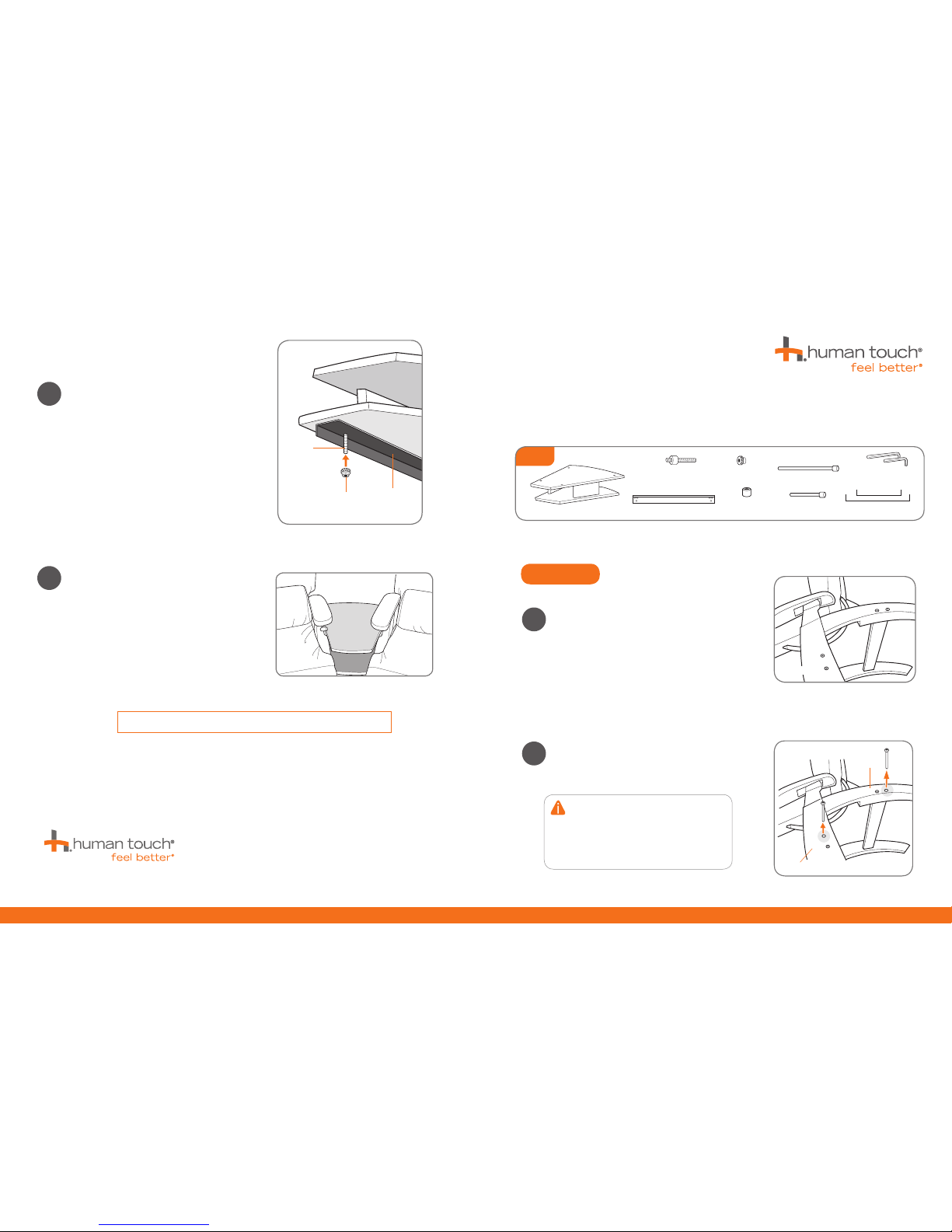
Installing your Perfect Chair® Wedge Spanner Table.
Place the first chair on its side on a soft surface with the
side on which you want to mount the table facing up.
GET READY
Remove the two bolts shown in Fig. 2. Save both
bolts in case you wish to restore your chair to its
original configuration later.
NOTE: While removing the two screws, one or
more barrel nuts may fall out of the cross bar
on the chair frame. If this occurs, reinsert the
barrel nut onto the cross bar, then turn it so
that the notch in the barrel nut runs parallel
to the chair leg.
1
2
Fig. 2
Fig. 1
Parts
Mounting bracket (2)
Small spacer (6)
Allen key
(1 long, 1 short)
Short bolt
Long bolt
Table
Spacer wire (1 long, 1 short)
Mounting screw
pin (4)
Locking knob (4)
Back leg
Front leg
Front leg
Locking knob
Mounting
bracket
Mounting
pin
Install a locking knob on the underside of each mounting
pin to secure the table firmly to the mounting brackets.
Install the locking knob large end facing up.
Your PC Spanner table installation is now complete.
Retain the four bolts you removed from your chairs in
case you want to return your chairs to their original
configuration. You can also add more spanner tables
and chairs to expand your layout. Enjoy!
9
10
Back leg
Please send any questions or comments regarding these instructions to: documentation@humantouch.com
© 2011 Human Touch®, LLC.
PC-WST-A0
Questions? Call Human Touch Customer Service at 800-355-2762.
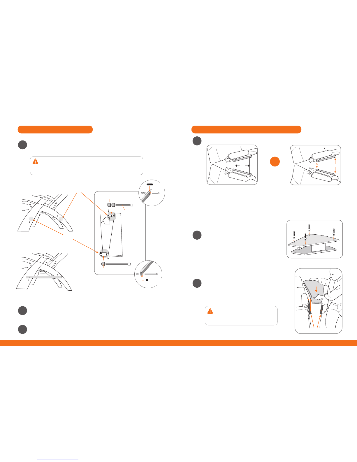
Place two spacers over the back leg screw hole, align the long hole on the mounting bracket
with the spacer hole, then secure the spacers and bracket using one of the short bolts (Fig.3).
Hand-tighten the bolt, leaving it slightly loose.
Place one spacer over the front leg screw hole, align the round hole on the mounting bracket
with the spacer hole, then secure the spacer and bracket using one of the long bolts (Fig.3).
Use a provided Allen wrench to tighten both the front and rear bolts.
Repeat steps 1 - 4 to install the mounting bracket on the opposite side of the second chair.
3
4
5
2 spacers
Short bolt
spacer Long bolt
Mounting
bracket
Mounting
bracket
(Fig.3)
Back leg screw hole
Front leg screw hole
INSTALL THE MOUNTING BRACKETS INSTALL THE TABLE ONTO THE MOUNTING BRACKETS
NOTE: If you are unable to insert the bolt, the barrel nut installed in the cross
bar is not properly aligned. Use your fingernail or a flat-head screwdriver to
turn the nut so that the notch runs parallel to the chair leg, then hold the
barrel nut in place while tightening the bolt.
Remove the table from the packaging, then carefully
place it face-down on a soft surface.
Install and hand-tighten the four mounting screw pins
as shown in Fig. 6.
Grasp the table with screw pins installed then lower the
table between the chair arms, aligning the mounting screw
pins with the corresponding holes in the mounting brackets.
Press down firmly to secure the table into the mounting
brackets (Fig.7). You may need to adjust the chair position
to align all four pins.
7
8
Fig. 6
Fig. 7
Position both chairs in the desired location. Do one of the following:
6
OR
Use a ruler to space the chairs as
shown in Fig. 5.
16.5”6.5”
Fig. 5
Insert the alignment wires into the bracket
holes, pulling the chairs apart so the wires are
tight, as shown in Fig. 4. Remove the wires
after positioning; retain them for future use.
Fig. 4
Wire
Mounting screw pin
Mounting bracket
NOTE: If there are rubber grommets installed
in the mounting brackets, they may pop out
while installing the table. Replace them before
completing the installation.
Short bolt goes
through the long hole
Long bolt goes
through the round hole
Put wire solution before measure solution.
 Loading...