

Page 1
Tools Required: Ruler, Locktite, 5/16-inch Allen wrench, 10-mm wrench, pliers, small flat-head screwdriver.
NOTE: This procedure can be completed by one person, although having a second person is helpful when installing the new backrest. SAVE ALL PARTS FOR USE DURING REASSEMBLY.
1. Remove the body pad and head pillow from the chair (for more information, see Use & Care manual).
2. Fully recline the chair. NOTE: If you cannot recline the chair using the recline lever, tip the chair gently on its
side, then while using a flat-head screwdriver to push the brake tab toward the brake cable, manually move the
chair to the fully reclined position. (Fig.10).
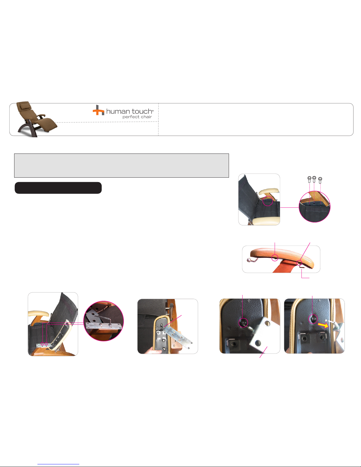
3. Using a 5/16” Allen wrench, remove the three Allen bolts located on the left-hand inner side panel (Fig.1).
4. Using a 5/16” Allen wrench, remove the four Allen bolts located on the underside of the left-hand armrest,
which secure the armrest to the mounting plate (Fig.2).
5. Lift the left-hand armrest up to expose two bolts beneath it, then use a 5/16” Allen wrench to remove the
two bolts, freeing the mounting plate from the chair. Turn the armrest upside down (Fig. 4).
6. Using your fingers, fold back the armrest upholstery on the underside of the armrest at the rear of the
mounting plate to expose the cable end (Fig.5).
7. Locate the clamp on the underside of the armrest that secures the cable end, then use a wire cutter to split
open the clamp, freeing the cable end. CAUTION: Be careful not to damage the cable (Fig.5).
REMOVING THE BRAKE CABLE
1
SERVICE LEVEL: 3
June 28, 2016
REPLACING THE BRAKE CABLE
PC-6/PC-410/PC-420
Allen bolt
(Fig.2)
(Fig.3)
Cable
Split open the clamp
Clamp
Mounting
Plate
(Fig.5)
2 Allen bolts front 2 Allen bolts back
Allen wrench
(Fig.1)
(Fig.4)
It is imperative that Human Touch® products are repaired in a manner that ensures product safety and regulatory compliance and that is
fully consistent with the practices used during the manufacturing process. Therefore, Human Touch requires that all product repairs are
performed using only factory-new parts and in accordance with these repair instructions. Failure to adhere to these instructions voids the
product warranty and releases Human Touch from all liability for injury or product damage resulting from the repair.
Page 2
2
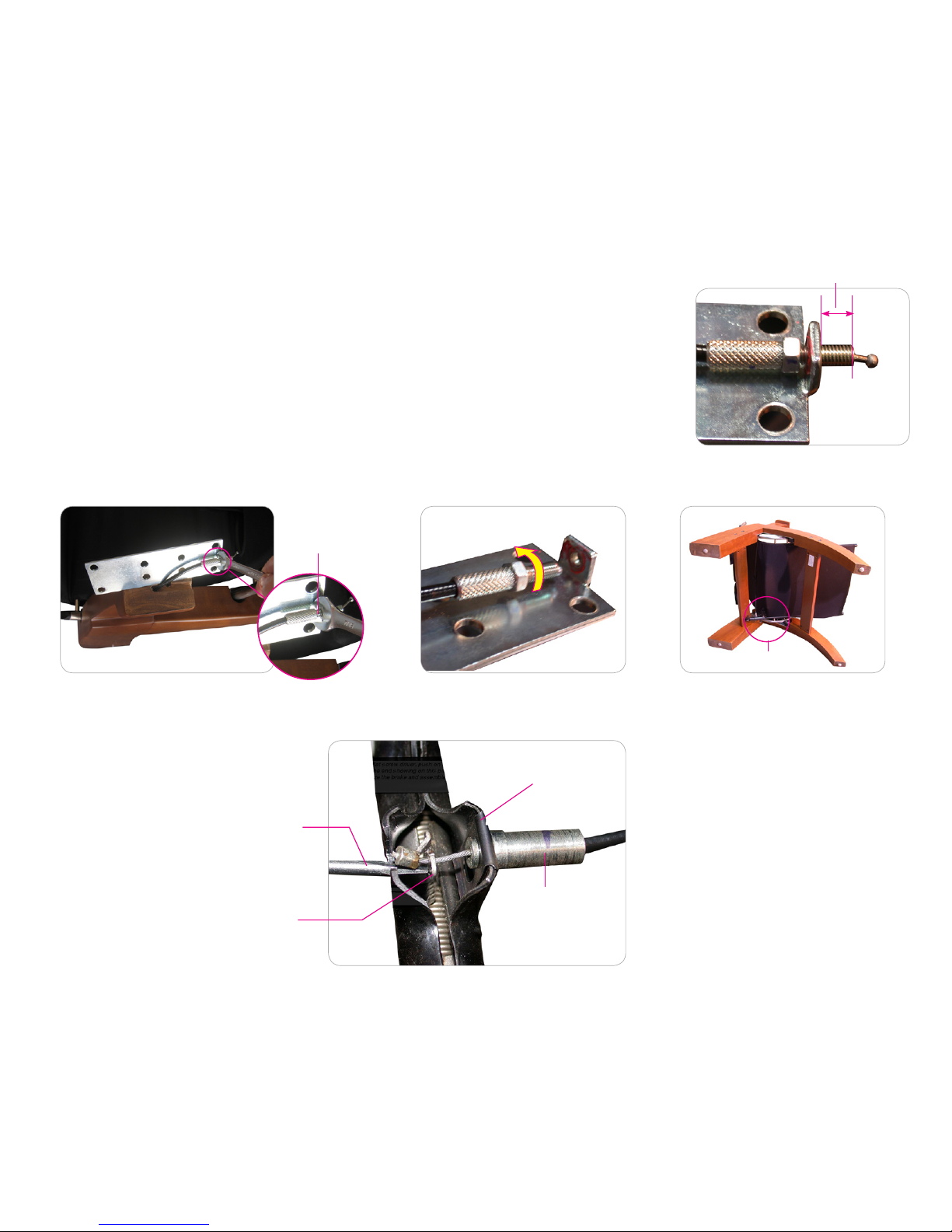
8. Locate the nut that secures the cable to the mounting plate, then measure the amount of threaded cable visible on the side of
the bracket opposite the nut. You will need this measurement when installing the new cable, to adjust the cable tension properly (Fig.6).
9. Using a 10mm open wrench, loosen the nut (Fig.7).
10. Using a pair of pliers, unscrew the bolt to remove it from the bracket, then remove the nut (Fig.8).
11. Gently tip the chair onto its left-hand, then locate the brake on the underside of the chair (Fig.9).
12. Using a small flat-head screwdriver, lift and remove the cable retaining clip and cable from the brake. TIP: Note the positioning
of the retaining clip and cable, for reinstallation (Fig.10).
13. From the rear of the chair, gently pull the cable through and remove it from the chair.
(Fig.6)
Measure
Loosen the nut
(Fig.7) (Fig.8) (Fig.9)
Retaining clip
Brake cable
Brake tab
Small flat-head screwdriver
(Fig.10)
Brake
Page 3

1. Remove the retaining clip from the old brake calbe and install it onto the new brake cable.
2. Install the retaining clip and cable onto the brake, until it clicks into place (Fig.11).
3. Using a small flat-head screwdriver, push the tab inward and hold it, use your fingers or a needle-nosed pliers to gently thread the cable end through the brake tab, then release the tab. (Fig.11).
4. Route the cable through the fabric tab on the underside of the chair canvas, under the glide rail, between the glide rail and the leg, through the cable guide on the inside of
the left-hand side panel, and up through the wood arm (Fig.12).
5. Gently return the chair to an upright position.
6. Place the nut back onto the cable, then thread the cable end through the metal bracket on the underside of the armrest.
7. Position the cable with the same amount of threading visible on the side of the bracket facing the cable end as you measured prior to removing the cable (Fig.13).
8. Apply a small amount of Locktite to the threads on the nut side of the bracket, then use a 10mm wrench to tighten the nut to secure it firmly against the metal bracket.
INSTALLING THE NEW CABLE
Retainer clip
Recline/Brake cable
Brake tab
Small flat-head
screwdriver
(Fig.11)
Cable
Wood arm
Cable
(Fig.12)
3
(Fig.13)
Measure
Page 4

1. Recline and incline the chair to ensure that the brake is operating smoothly.
2. If the brake does not lock the chair in place when the brake lever is released, remove the armrest and then:
a. Loosen the nut at the end of the cable on the underside of the armrest, then turn the bolt clockwise one revolution (Fig.19).
b. Tighten the nut.
c. Recline and incline the chair to test the brake operation.
d. If the problem still exists, repeat steps a through c.
3. If the chair does not recline when the brake lever is pulled up, remove the armrest and then:
a. Loosen the nut at the end of the cable on the underside of the chair, then turn the bolt counter-clockwise one revolution (Fig.20).
b. Tighten the nut.
c. Recline and incline the chair to test the brake operation.
d. If the problem still exists, repeat steps a through c.
TESTING/ADJUSTING THE CABLE
4
© 2016 Human Touch®, LLC.
9. Install the cable end into the cable clamp, then use a needle-nosed pliers to gently crimp the cable
clamp closed, securing the cable (Fig.14).
10. Position the armrest mounting plate onto the wood arm, then, using a 5/16” Allen wrench, replace
the two Allen bolts to secure it (Fig.15). NOTE: You may need to reposition the slotted receiving
stud on the wood arm to align the bolt holes properly (Fig.16).
11. Place the armrest into position, then use a 5/16” Allen wrench to replace the four Allen bolts,
securing the armrest to the chair (Fig.17).
12. Place the left-hand inner side panel into position, then use a 5/16”Allen wrench to replace
the three Allen bolts, securing the side panel to the chair (Fig.18).
(Fig.16)
Cable clamp
(Fig.14)
(Fig.15)
(Fig.17)
2 Allen bolt front 2 Allen bolt back
Allen wrench
Allen bolt
(Fig.18)
Stud
(Fig.19)
(Fig.20)
 Loading...