

Page 1
HT-7120
March 14, 2012
REPLACING THE FOOT AND CALF MASSAGER
To ensure that Human Touch® products are repaired in a manner that is fully consistent with the practices used during the manufacturing process, Human Touch requires that all
product repairs are performed using only factory-new parts and in accordance with these product repair instructions.
Tools Required: Nail clipper or other instrument suitable for cutting zip ties, Phillips-head screwdriver, flat-head
screwdriver, vice grip, small hammer.
NOTE: SAVE ALL SCREWS FOR USE DURING REASSEMBLY.
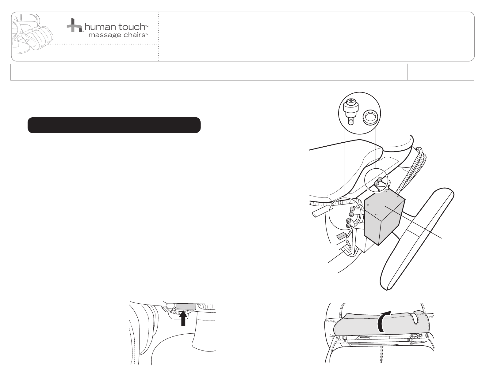
Screw/washer
REMOVING THE FOOT AND CALF MASSAGER
1. Lift the foot and calf massager up, then place a box or other sturdy object beneath it
for support.
2. Locate the air pump on the bottom of the chair, then remove the six sets of screws/washers
that secure the pump to the chair (Fig. 1).
3. Locate the connector box on the bottom left side of the chair, near the foot and calf
massager (Fig.2).
4. Using a Phillips-head screwdriver, remove the two screws that secure the connector box cover,
remove the cover, then disconnect the red connector.
5. Cut any zip ties that secure the cable that runs from the connector box to the foot and calf
massager, to free the cable from the chair base.
6. Remove the box or other sturdy object that is supporting the foot and calf massager,
allowing the massager to drop down to a vertical position.
7. Standing in front of the foot and calf massager, detach the upholstered flap that covers the
massager frame (Fig.3).
NOTE: It is helpful to flip the upholstered flap up onto the seat cushion and place an object on
top of it to hold it out of the way.
(Fig.1)
SERVICE LEVEL: 3
Air pump
(Fig.2)
(Fig.3)
1
Page 2
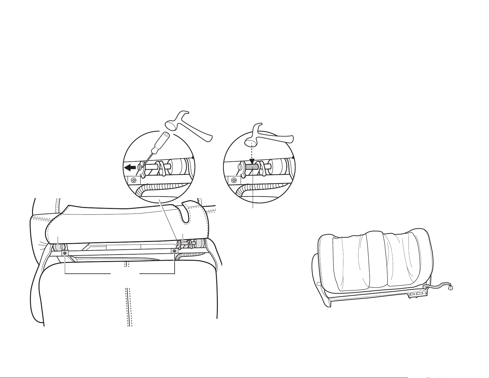
8. Using a Phillips-head screwdriver, remove the two screws from the two brackets on the massager frame, then remove the brackets (Fig.4).
9. Locate Pin A, insert a flat-head screwdriver between the pin head and the bracket, then tap the screwdriver handle to dislodge the pin from
the bracket approximately 1/2 inch (Fig.4). NOTE: If the pin is stuck in the bracket, tap the pin with a hammer on the exposed area between
the two sides of the mounting bracket to loosen it (Fig.4).
10. Use your hand or a vice grip to remove Pin A completely from the bracket, allowing the calf massager to drop toward the floor.
11. Pull the calf massager away from Pin B to remove it from the chair. (Fig.5).
If the pin is stuck in
the bracket, tap the
pin with a hammer
Pin B
Brackets
(Fig.4)
Pin
Pin A
(Fig.5)
2
Page 3

INSTALLING THE NEW FOOT AND CALF MASSAGER
1. Place the new foot and calf massager into position, then insert pin A just far enough into the left side of bracket A to hold it in place.
2. Line up the actuator bracket with the mounting point on Bracket A, then push the pin through the bracket as far as it will go by hand.
3. Line up the left side of the massager with Bracket B, then insert Pin B through the bracket as far as it will go by hand.
4. Use a small hammer to push both pins until the pin heads are flush with the bracket.
5. Replace the two brackets on the front of the massager frame and secure them using a Phillips-head screwdriver and two screws.
6. Lift the massager up, then insert a box or other sturdy object beneath it for support.
7. Reconnect the red connectors on the lower left-hand side of the backrest.
8. Replace the connector box cover and secure it, using a Phillips-head screwdriver and two screws.
9. Place the air pump into position, then secure it with the six sets of screws/washers.
10. Install new zip ties to replace those you removed earlier, to secure the massager cabling to the chair base, out of sight.
11. Reinstall the upholstered flap, by wrapping it around the massager frame and securing it using the hook and loop fasteners.
Pin B
Please send any questions or comments regarding these instructions to: documentation@humantouch.com
© 2012 Human Touch®, LLC.
Bracket B
Brackets
Pin A
Actuator bracket
Pin A
Bracket A
Bracket A
Actuator bracket
3
 Loading...