

Page 1
HT-2580/iJoy-2580
replacing THe BacKreST acTUaTOr
Aug 20, 2009
X1103
To ensure that Human Touch® products are repaired in a manner that is fully consistent with the practices used during the manufacturing process, Human Touch requires that all
product repairs are performed using only factory-new parts and in accordance with these product repair instructions.
Tools Required: needle-nosed pliers, Phillips-head screwdriver, 4-mm Allen Key, instrument suitable for cutting zip ties, new zip ties.
SAVE ALL REMOVED PARTS FOR USE DURING REASSEMBLY
REMOVING THE RECLINE ACTUATOR
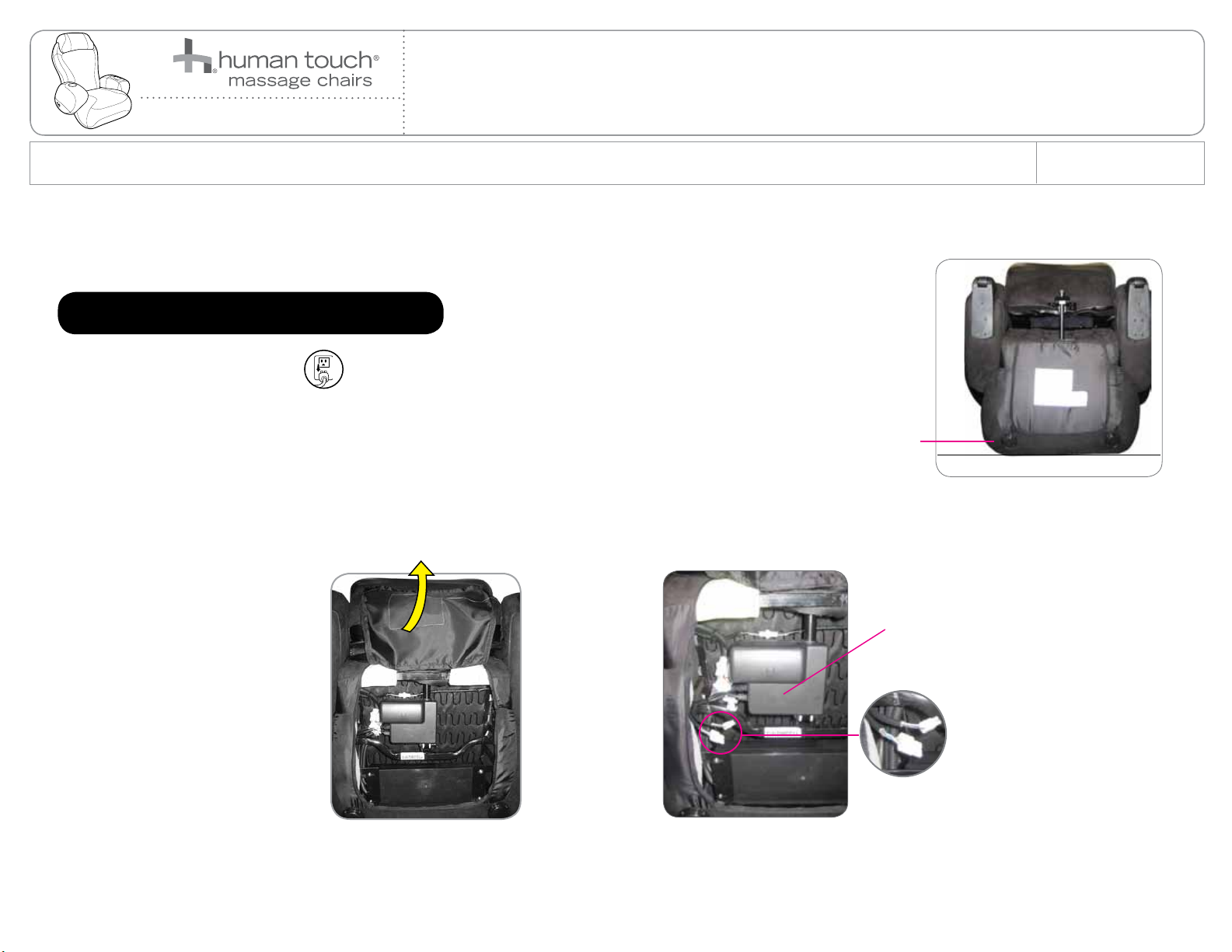
1. Power off the chair then unplug it.
2. Gently tip the chair forward to rest the headrest on the floor (Fig.1).
3. Using an instrument suitable for cutting zip ties, cut the zip tie that secures the two zippers on the bottom of the chair,
then open both zippers (Fig.2).
4. Using an instrument suitable for cutting zip ties, cut the zip ties that secure the cable bundle.
5. Follow the cable harness from the actuator to the cable bundle, then disconnect the two backrest actuator connectors (Fig.3).
Seat
SERVICE LEVEL: 3
(Fig.1)
(Fig.2) (Fig.3)
Actuator
Connectors
1
Page 2
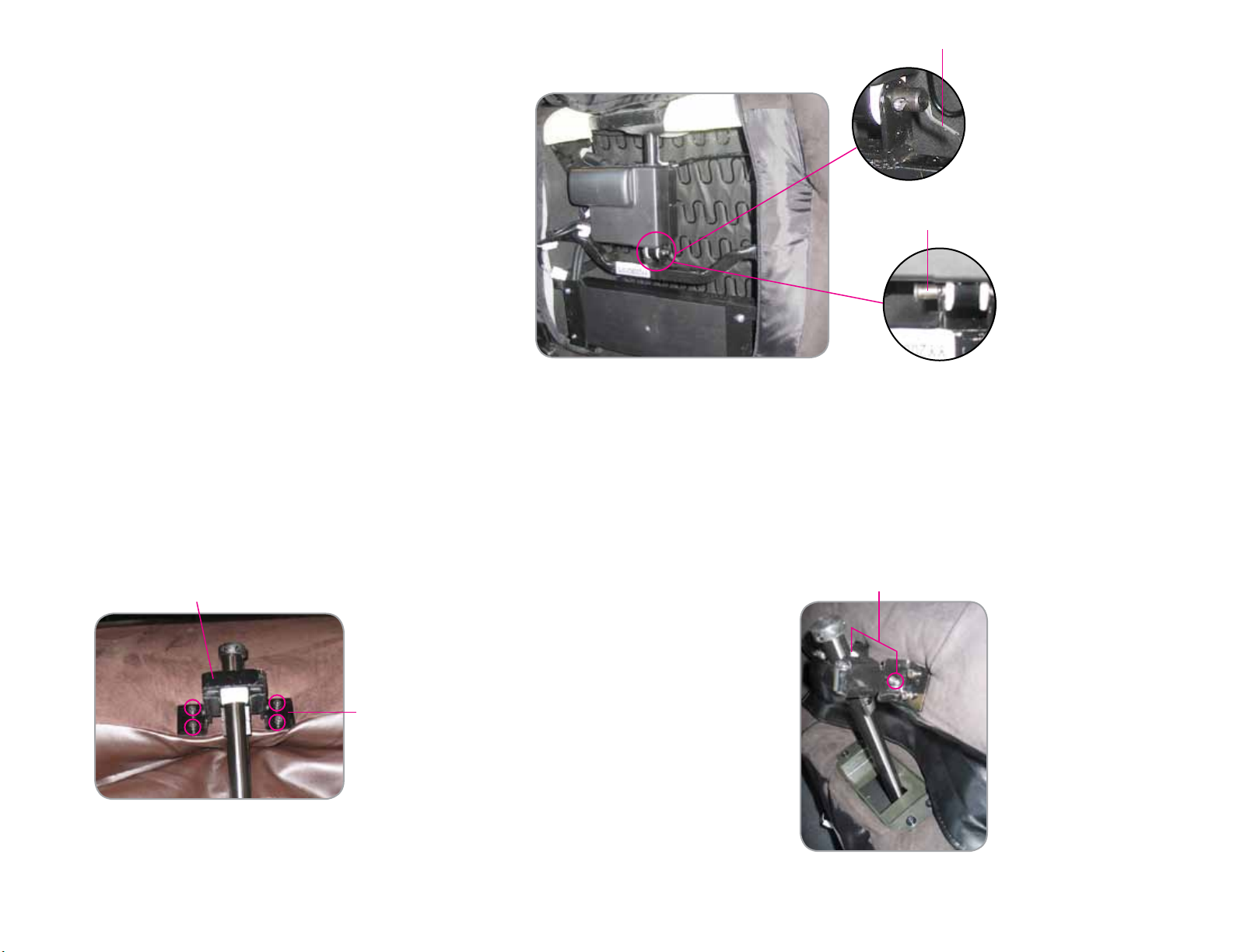
6. Using a needle-nosed pliers, remove the cotter pin that secures the backrest actuator mounting pin (Fig.4).
Cotter pin
7. Using a needle-nosed pliers, remove the hinge pin (Fig.4).
Hinge pin
(Fig.4)
8. Flip the underseat cloth back down to cover the actuator, then locate the bracket that holds the actuator shaft in place at the rear of the seat (Fig.5).
9. Using a 4-mm Allen Key, remove the four screws/washers that secure the bracket to the chair (Fig.5).
10. Using a Phillips-head screwdriver, remove the screw/washer on each side of the bracket, which secure the metal plate behind the shaft to the bracket, then remove the metal plate to
free the actuator shaft from the bracket (Fig.6).
11. Pull the actuator shaft down, through the opening in the upholstery, then remove the actuator from the bottom of the chair.
Bracket
Phillips-head screw
Using a 4-mm Allen Key,
remove the four screws
(Fig.5)
(Fig.6)
2
Page 3

INSTALLING THE NEW ACTUATOR
1. From the bottom of the chair, thread the new actuator shaft up through the opening in the upholstery at the rear of the seat. IMPORTANT: Make sure the black spacer on each
side of the actuator shaft stays in place.
2. Align the actuator mounting point with the mounting bracket on the bottom of the chair, then replace the hinge pin and cotter pin to secure the actuator (Fig.7).
3. Flip the cloth down to cover the bottom of the chair.
4. Turn the two black spacers on the end of the actuator shaft so the short side is on top, then slide the spacers into the mounting bracket (Fig.8).
Cotter pin
New actuator
Black spacer Mounting brackerActuator shalf
Hinge pin
(Fig.7)
Actuator shalf
Black spacer
(Fig.8)
Black spacer
3
Page 4

5. Insert the metal plate behind the actuator shaft, aligning the holes on the ends of the plate with the holes on each side of the mounting bracket. IMPORTANT: Be sure the bracket
is turned so it is on the side of the screw holes opposite the actuator shaft (Fig.9).
6. Replace the two screws/washers to secure the metal plate to the bracket (Fig.10).
7. Align the mounting bracket holes with the corresponding holes on the back of the chair, then use a 4-mm Allen key to replace the four screws/washers (Fig.11).
8. Connect the actuator connectors to the corresponding connectors on the bottom of the chair, then secure the connectors using new zip ties (Fig.12).
9. Close the zipper on the bottom of the chair.
10. Plug in the chair, power it on, then verify that the chair now reclines/inclines properly.
Phillips-head screw
Black spacer
Actuator shaft
(Fig.9)
Bracket
Metal plate
Mounting bracket
Using a 4-mm Allen Key,
remove the four screws
Black spacer
(Fig.10)
Actuator shaft
New actuator
Connectors
Actuator shaft
(Fig.11)
Please send any questions or comments regarding these instructions to: documentation@humantouch.com
© 2008 Human Touch®, LLC.
(Fig.12)
4
 Loading...