

Page 1
INSTALLATION INSTRUCTIONS
PATENT PENDING
G
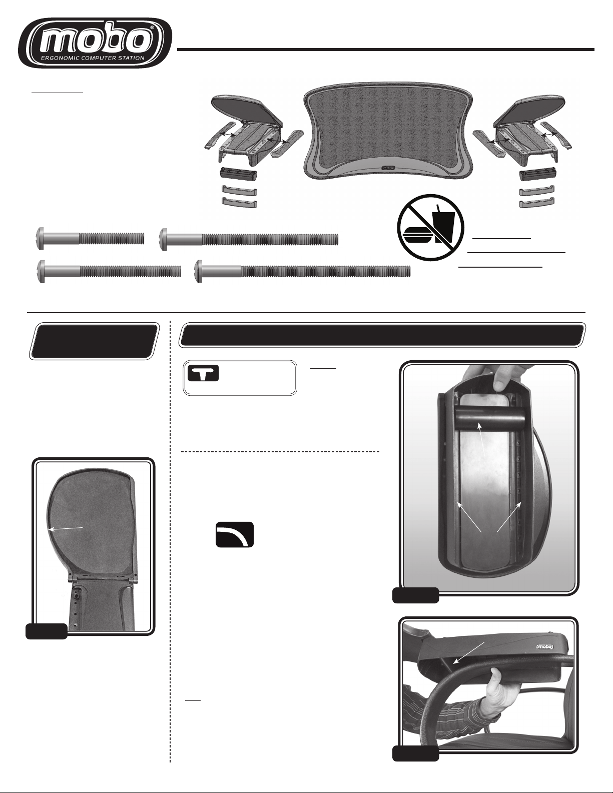
PARTS LIST:
A
A) LEFT BASE UNIT (1)
B) L2 - Inside CAP - straight edge (1)
C) R2 - Outside CAP - curved edge (1)
BC
D) RIGHT BASE UNIT (1)
E) L1 - Inside CAP - straight edge (1)
F) R1 - Outside CAP - curved edge (1)
G) KEYBOARD TRAY (1)
H) CURVE ADAPTERS - For chairs with
curved armrests (2)
I) MOUNTING CLAMPS (4)
H H
I
J) Hardware: Screws -
WARNING!
8/32 x 1.5” (8)
8/32 x 2.5” (8)
8/32 x 2” (8) 8/32 x 3” (8)
READ THROUGH INSTRUCTIONS BEFORE BEGINNING. DO NOT FULLY TIGHTEN SCREWS UNTIL INSTRUCTED.
NOT FOR USE WITH
FOOD OR DRINK!
D
FE
I
IDENTIFY
CORRECT PARTS
STEP 1: IDENTIFY AND
SORT BASE UNIT PARTS
Flip open both BASE UNITS into the
mouse pad position. The curved side
of each BASE UNIT should face to the
outside when installed (FIG 1).
CURVED
EDGE TO THE
OUTSIDE
LEFT
BAS E UNIT
FIG 1A
INSTALL ADAPTER FOR EXTREMELY CURVED ARMRESTS
If your chair has flat
or T-shaped armrests,
skip to STEP 5.
UNITs are parallel to t he ch ai r armrest and ful ly
supported, you do not need the CURVE ADAPTER and
can skip this step.
STEP 2: INSTALL CURVE ADAPTER
A CURVE ADAPTER is required to provide support where
the chair armrest begins to curve, to keep the BASE UNIT
flat and level with the chair armrest.
Install Curve Adapter for
use with extremely curved
or sloping armrests.
FIG 2A: To install the CURVE ADAPTER, turn the LEFT BASE
UNIT over to view the bottom. Insert the CURVE ADAPTER
into the first set of rectangular slots that are located along
each side wall.
FIG 2B: Place the LEFT BASE UNIT over the left chair armrest to check for proper ADAPTER placement. If the MOBO
BASE UNIT is angled up or down, move the ADAPTER back,
one slot at a time, until the base unit is level.
Once you have the CURVE ADAPTER in the correct position,
install the other CURVE ADAPTER into the remaining RIGHT
BASE UNIT using the same slot location.
NOTE : Not every
chai r with curv ed
arms requi res th e
CURVE ADAPTER
the MOBO BASE
. If
FIG 2A
CURVE
ADAPTER
MOUNTING
SLOTS
(A long bot h walls)
CURVE
ADAPTER
Version: 1.3 (07/13/09)
TIP: If your chair’s armrest has padding, the placeme nt of the ADAPTER shoul d have the MOB O BASE
UNIT angle d up slig htly. This will allow the b ase u nit
to be come lev el once the clam ps have been tig htened
and the padding is c omp re ssed. O therwis e, the base
unit may angle downward once it is fully tightened.
1
FIG 2B
Page 2
INSTALLATION INSTRUCTIONS (Continued)
If your chair has flat or T-shaped armrests, skip to STEP 5.
CURVED & OPEN
INSTALLING ON CURVED ARMRESTS
ARMRESTS
IMPORTANT TIPS & NOTES:
(USE THE SHORTEST SC REW
THAT WILL REACH THE CLAMPS)
Try t o us e sc re w
leng ths th at
will minimize
or el imin at e
ex ce ss s crew
leng th f rom th e
bo tto m of the
clamp, wh en
fully tightened.
STEP 3: INSTALL THE REAR MOUNTING CLAMP
Place the opened LEFT BASE UNIT over the left chair armrest. (Curved side of the
base unit and mouse pad should face to the outside). While holding the base unit
in an approximated position, insert the shortest screws into the hole set closest the rear of the base unit. Try to keep the MOUNTING CLAMP on the flattest
areas of the armrest, avoiding the curved areas. Some chairs will allow you to
use the very last hole set and others may require you to use a hole set further up
(Second or third hole set from the end, etc.).
FIG 3 (A): Place the MOUNTING CLAMP under the chair armrest and align it
with the screws. Push the CLAMP up against the bot tom of the chair armrest. If
the CLAMP pushes the screws up more than 1/2” above the BASE UNIT, replace
the screws with a shorter size.
NOTE : Only 8 total screws are
neede d to i nsta ll yo ur Mobo. Save
the unused screws in case you
decide to install your Mobo on a
different chair.
TIP: So me chair a rm rests wi ll not
require the sa me leng th screws
in the front and rear. Some armrests may require longer screws
in the front than in the rear or
Replace with shorter screws.
visa-versa (Usually when th e
CU RVE ADAPTER is used).
TIP: S ta rting the screws into the
clamp is easier if you squeeze the
clamp snug under the armrest.
This will k eep t he sc rew he ads
rai sed wh ere the y can easily be
turned. Barely tighten the first
side, an d it wi ll be easier to s ta rt
the screw on the opposite side.
Screws are too long.
(B)
(A)
FIG 3 (B): Tighten the screws until the BASE UNIT is snug against the armrest,
but can still be moved.
DO NOT FUL LY TIGHTEN SC RE WS
.
STEP 4: INSTALL THE FRONT MOUNTING CLAMP
Insert screws into the hole set closest to the front as possible, while making sure
to keep the MOUNTING CLAMP on the flattest areas of the armrest, avoiding
the cur ved areas. Some chairs will allow you to use the very front hole set and
others may require you to use a hole set further back (Second or third hole set
from the front end, etc.).
FIG 4 (A): Place the MOUNTING CLAMP under the chair armrest and align it
with the screws. Push the CLAMP up against the bottom of the chair armrest.
If the CLAMP pushes the screws up more than 1/2” above the BASE UNIT,
replace the screws with a shorter size.
FIG 4 (B): Make sure the CURVE ADAPTER (Step 2) is positioned correctly across
the armrest, where the curve begins. This should provide support and help keep
the Mobo parallel (level) with the armrest. If the placement isn’t correct, adjust
adapter before proceeding.
FIG 4 (C): Tighten the screws until the BASE UNIT is snug against the armrest,
but can still be moved.
DO NOT FUL LY TIGHTEN SC RE WS
.
FIG 3
FIG 4
(B)
CURVED
ARMREST
(C)
(A)
CURVE
ADAPTER
MOUNTING
CLAMP
MOUNTING
CLAMPS
REPE AT STEPS 1 - 4 FOR THE OPPOSITE MOBO BASE UNIT, THEN PROCEED TO STEP 7 (FINAL ADJUSTMENTS & TIGHTENING).
2
Page 3
If your chair has curved armrests and you have completed steps 3 & 4, skip to STEP 7.
FLAT & T-SHAPED
INSTALLING ON FLAT ARMRESTS
ARMRESTS
IMPORTANT TIPS & NOTES:
(USE THE SHORTEST SC REW
THAT WILL REACH THE CLAMPS)
Try to use screw
lengths that
will minimize or
eliminate excess
screw length from
the bottom of the
clamp, when fully
tightened.
STEP 5: INSTALL THE REAR MOUNTING CLAMP
Place the opened LEFT BASE UNIT over the left chair armrest. (Curved side of
the base unit and mouse pad should face to the outside). While holding the base
unit in an approximated position, inser t the shortest screws into the hole set
closest the rear of the base unit. Make sure the MOUNTING CLAMP will catch
under the chair armrest. Some chairs will allow you to use the very last hole set
and others may require you to use a hole set fur ther up (Second or third hole set
from the end, etc.).
FIG 5 (A): Place the MOUNTING CLAMP under the chair armrest and align it
with the screws. Push the CLAMP up against the bot tom of the chair armrest. If
the CLAMP pushes the screws up more than 1/2” above the BASE UNIT, replace
the screws with a shorter size.
FIG 5 (B): Tighten the screws until the BASE UNIT is snug against the armrest,
but can still be moved.
DO NOT FUL LY TIGHTEN SC RE WS
.
NOTE : O nly 8 total s crews are
neede d to i nsta ll yo ur Mobo. Save
the unused screws in case you
decide to install your Mobo on a
different chair.
TIP: So me chair a rm rests wi ll not
require the sa me leng th screws
in the front and rear. Some armrests may require longer screws
in the front than in the rear.
Replace with shorter screws.
TIP: S ta rting the screws into the
clamp is easier if you squeeze the
clamp snug under the armrest.
This will k eep t he sc rew he ads
rai sed wh ere the y can easily be
turned. Barely tighten the first
side, an d it wi ll be easier to s ta rt
the screw on the opposite side.
Screws are too long.
(B)
(A)
MOUNTING
CLAMP
FIG 5
STEP 6: INSTALL THE FRONT MOUNTING CLAMP
Insert screws into the hole set closest to the front as possible, while making
sure the MOUNTING CLAMP will catch under the chair armrest. Some chairs will
allow you to use the very front hole set and others may require you to use a hole
set fur ther back (Second or third hole set from the front end, etc.).
FIG 6 (A): Place the MOUNTING CLAMP under the chair armrest and align it
with the screws. Push the CLAMP up against the bottom of the chair armrest.
If the CLAMP pushes the screws up more than 1/2” above the BASE UNIT,
replace the screws with a shorter size.
FIG 6 (B): Tighten the screws until the BASE UNIT is snug against the armrest,
but can still be moved.
(A) (B)
DO NOT FUL LY TIGHTEN SC RE WS
I M PORTA NT: There must be a clamp
on either side of the T-shaped armrest
“post” (A) Front & (B) Rear.
.
FIG 6
REPE AT STEPS 1-2 & 5 -6 FOR THE OPPOSITE MOBO BASE UNIT, THEN PROCEED TO STEP 7 (FINAL ADJUSTMENTS & TIGHTENING).
(A)
(B)
MOUNTING
CLAMP
3
Page 4
INSTALLATION INSTRUCTIONS (Continued)
FINAL POSITIONING, ADJUSTMENTS AND CLAMP TIGHTENING
STEP 7: ADJUSTING LOOSELY INSTALLED BASE UNITS
Flip the mouse pad areas out, into the open/extended position. Sit back in your chair in
a comfor table, relaxed position. With your elbows and forearms resting on the mobo,
in a natural position, your hands should fall in the centers of the mouse pad areas.
If your hands do not fall close to the center of the mouse pad area slide both MOBO
BASE UNITS either forwards or backwards until they do.
FIG 7A: The BASE UNIT needs to be moved forward on the chair armrest.
FIG 7B: This is the correct position for the BASE UNIT.
NOTE : If the MOBO BASE UNIT will not move in the direction needed, you
may have to reposition one or more of the clamps, to allow them to slide in
the direction required, to achieve proper hand positioning.
CURVED ARMRESTS: If you have to reposition the MOBO BASE UNITS and
you installed the CURVE ADAPTER, make sure to double check the ADAPTER
position, as well, before tightening clamps.
FIG 7A
FIG 7B
STEP 8: TIGHTEN CLAMPS
INCORRECT ANGLE
Once the final position has be en
determined, follow the guidelines
below for tightening the MOUNTING CLAMPS:
I M PORTA NT: Do not fu lly
tighten on e sc re w an d th en m ove
to the next one. Make sure to
keep each MOBO BASE UNIT
fla t and level by ti ghtenin g ea ch
screw equally, while alternating between the le ft and righ t
screws. If one side is tightened
mo re tha n th e other, it can ca use
CLAMP
ARMREST
FIG 8
IN CORR ECT: T he BAS E UNI T is tilt ed
inward. This is caused by the inside
screws being tighter than the outside.
the MOBO BASE UNIT to tilt inward or outward (FIG 8).
TIP: You can use this to your advantage as a leveling technique for
STEP 9: INSTALL CAPS
FIG 9 A: Look under the bottom of
each CAP and find the ID mark (FIG
9A). Match to the corresponding
ID mark on each BASE UNIT.
FIG 9B: Align posts on CAP with
the three raised cylinders along
the edge of the BASE UNIT and
firmly snap into place. Repeat for
all CAPS.
YOU AR E FINISHED
WIT H THE INSTA LL ATION.
ENJOY THE C OMFORT A ND
HEA LTHY POSTURE PROV IDE D
BY YOUR N EW MOBO.
CAP
FIG 9A
BAS E UNIT
sloped or slightly angled armrests when fine-tuning the installation of
the MOBO BASE UNITS. Simply tighten one side more than the other to
help offset any minor slopes. This technique can be used to also fine
tune the slope from front to back, on chairs with padded armrests.
Tighten the screws until the MOBO BASE UNIT is firmly secured to the armrest.
DO NOT OVE R TIGHT EN SCRE WS
DISCLAIMER: The MOBO may be dangerous if used improperly, negligently, or illegally. You should use the MOBO in a safe and legal manner, consistent with all applicable laws,
recognized safet y rules, and good common sense. For your safety and the safet y of others, follow these instr uctions:
1. DO NOT place food or drinks on the MOBO keyboard tray or mouse pad areas.
2. DO NOT place excessive force on the MOBO’s mouse pad areas w hile they are in an ex tended position. Placing excessive force on the mouse pad areas may cause the mouse pad
area to break, resulting in damage to your computer equipment and possible injury.
3. DO NOT use the MOBO’s mouse pad areas as support for getting into and ou t of your chair while the mouse pad areas are in an extended position. Using the MOBO’s mouse pad
areas as suppor t may cause your chair to flip over, causing damage to your chair, your computer equipment, and possible injury to you.
4. KEEP FINGERS CLEA R of hinged areas when opening or closing the mouse pad areas.
5. SUPERVISE CHILDREN who use t he MOBO. The MOBO is not a toy and may cause injury if used improperly.
When you purchase the MOBO, you agree to assume all risks related to or arising from your ownership and use of the MOBO and agree to indemnify and hold Ergobiz, LLC harmless
from any and all claims brought by any person or entit y against Ergobiz, LLC related to or arising f rom your ownership or use of the MOBO.
LIMITE D LIF ET IME WA RRANTY: All ErgoBiz, LLC. products are carefully inspected before leaving the factory. ErgoBiz, LLC. war rant s its pr oducts to be free of defects in
wor kmans hip and mater ials. If a p roduc t fails in normal use as a re sul t of de fects in workmanship or materials, pl ease r eturn it to the factory fo r in spect ion . If we deter mine
the failure was caused by a defect in workmanship or materials, the produc t will be replaced or at our op tion, repaired free of charge.
This Lifetime Warrant y covers only r epairs or replacement of products which are found to be defective in work manship or materials. It specifically does not cover “complete user satisfaction,” and is specifically void if the product has been abused, misused, altered or has been intentionally or accidentally damaged in any manner through
circumstances due to purchaser’s misuse, abuse or negligence.
.
FIG 9B
 Loading...