

HumanCentric 101-4001 User Manual
Wall Mount for 60"-100" curved & flat panel TVs up to 80kgs/176lbs
Model 101-4001
www.humancentric.com/patents
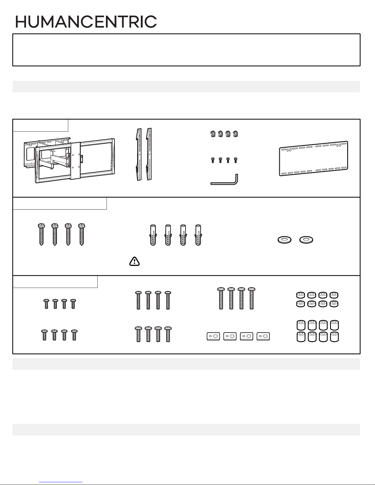
PARTS INCLUDED
Note: Not all parts will be used in the installation. Multiple configuration options are provided to fit
dierent TVs, and dierent parts are used for dierent configurations.
MOUNTING ARM
C Cable Clips (4)
D M4 Cable Clip Screws (4)
A Heavy-Duty Wall Mount (1) B TV Mounting Brackets (2)
E M4 Allen Wrench (1)
WALL MOUNTING HARDWARE
W-A Wall Mounting Screws (4) W-B Concrete Wall Anchors (4)
Warning: Not for use with drywall!
TV MOUNTING HARDWARE
M-A M5 x 14mm (4)
M-B M6 x 14mm (4)
You will choose the appropriate option for your TV shape and size
M-C M6 x 30mm (4)
M-D M8 x 30mm (4)
M-E M8 x 50mm (4)
M-F Metal Spacers (4)
W-C Wall Mounting Washers for Bottom Holes (2)
ADDITIONAL TOOLS REQUIRED
Phillips Head Screwdriver
Power drill with ½” (12mm) bit (solid concrete or concrete block) or ¼” (6mm) bit (wood stud)
Level
Marking Pencil
Edge-finding stud locator (for stud wall mounting)
Masking tape (to plan mounting location)
A friend to help lift the TV
F Drilling template (1)
M-G Small Spacer (8)
M-H Large Spacer (8)
COMPATIBLE WITH MODELS
Fits TVs with VESA patterns:
200x200, 300x300, 400x200, 400x400, 600x400, 800x400, 800x600, 900x600
© 2017 HumanCentric Ventures LLC
www.humancentric.com
1
Read the entire instruction manual, including the warnings at the end of the manual, before you start installation and
assembly. If you have any questions regarding any of the instructions or warnings, please contact the HumanCentric
support team for assistance at support@humancentric.com
CAUTION
Use with products heavier than the maximum weights indicated may result in damage to the mounted devices or
personal injury.
IMPORTANT
Ensure that you have received all parts according to the parts list prior to installation. If any parts are missing or
damaged, please contact the HumanCentric support team for replacements at support@humancentric.com
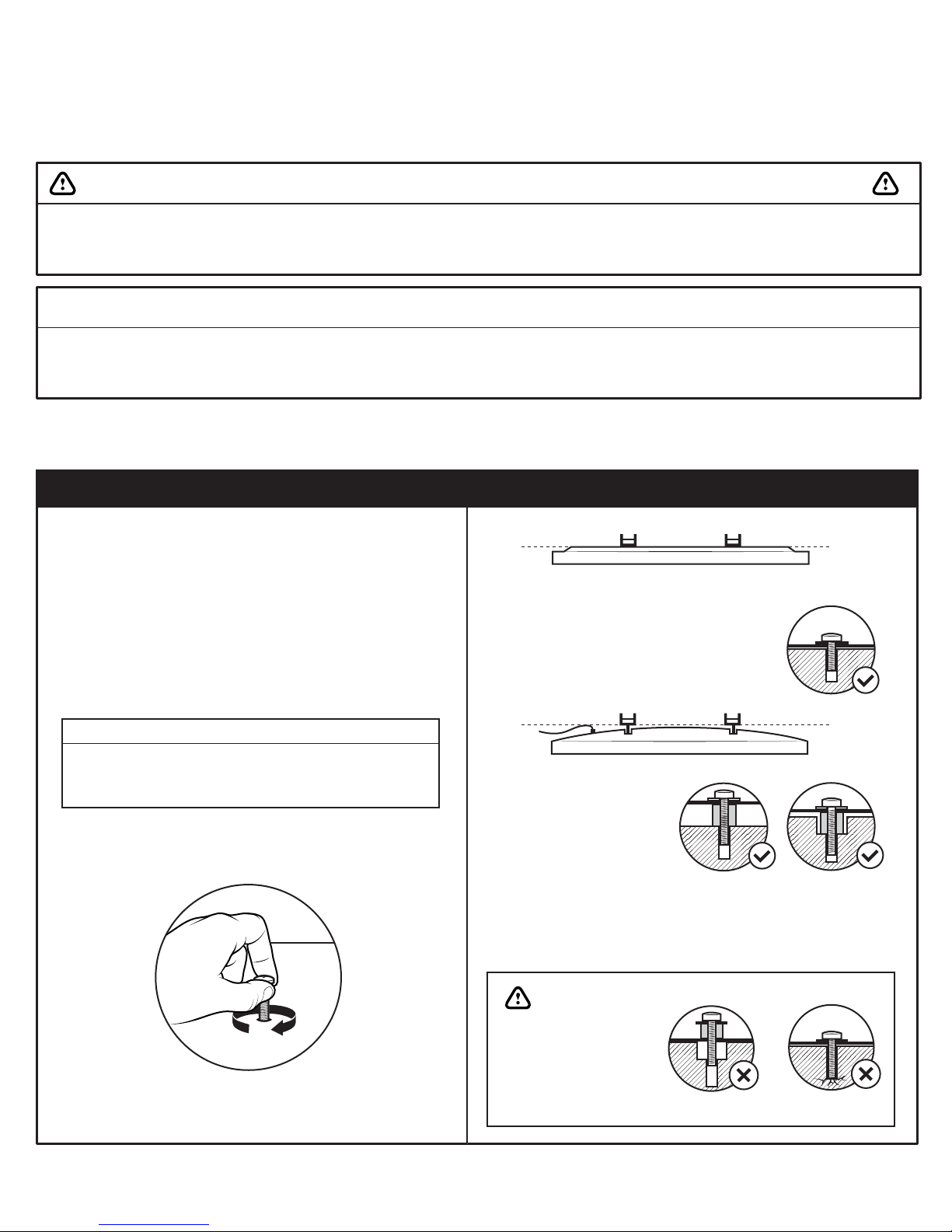
1. ATTACH MOUNTING BRACKETS TO TV
1A. Select Screws and Spacers
Hang tight - this step can take some trial and error to
find the right combination!
First, try dierent size screws included with the mounting
kit (M-A to M-E) to determine the correct screw diameter
for your TV.
Screw Diameters
M-A
M-B, M-C
M-D, M-E
5mm
6mm
8mm
Gently hand-tighten the screws to reach the end of the
hole, and take note of how far the screws stick out.
Flat back
If the mounting brackets lay flat on the
back of the TV and the mounting holes
on the TV are not inset, then you may
not need to use any spacers (depending
on screw length).
Round back
If it doesn’t lay flat on the
TV, if the holes are inset,
or if there are other
obstructions like cables,
then you must use the
large and small spacers
between the TV and the
bracket to create a flat,
even surface.
You may need to use up to two
large and two small spacers per
screw to achieve the correct fit.
Next, lay the mounting brackets on the back of the TV.
© 2017 HumanCentric Ventures LLC
Ensure that you choose
an appropriate length
screw and spacer
combination that is not
too long or too short:
Will not hold TV
Will damage TV
www.humancentric.com
2
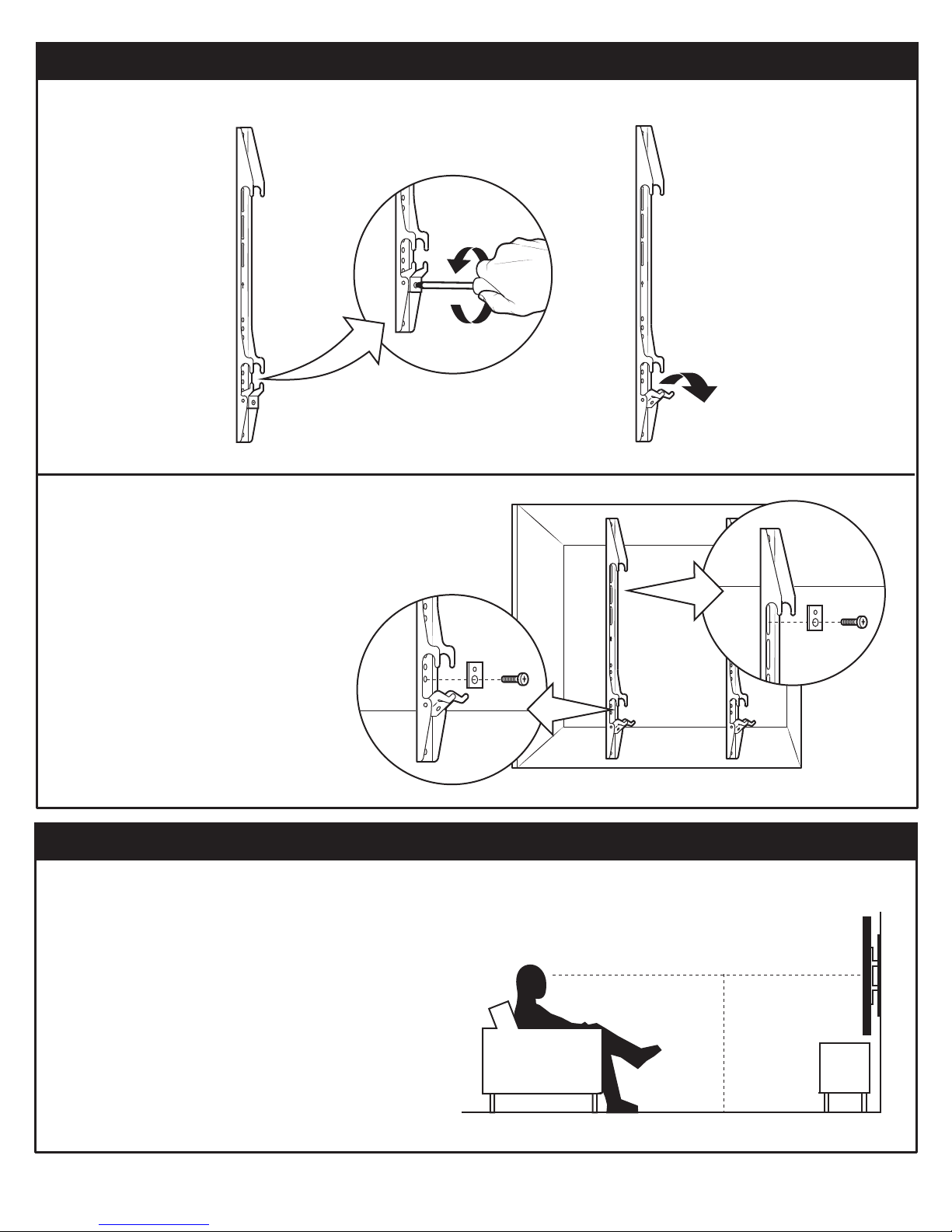
1. ATTACH MOUNTING BRACKETS TO TV
1B. Remove locking screws from Mounting Brackets
Using a Philips Head screwdriver,
remove the locking screw from
each of the mounting brackets.
1C. Attach Mounting Brackets to TV
Line up the holes on the brackets with the holes in the
back of the TV. Remember - the hooks which have the
locking screw should be oriented towards the bottom of
the TV.
Using the screw / spacer combination
you selected in the previous steps
and the square washers (M-F), attach
the mounting brackets to the back of
the TV as shown.
2. ATTACH MOUNTING ARM TO WALL
2A. Determine Mounting Height
The ideal height for a typical TV room setup is for the
middle of the TV to be 42” o the ground.
However, your optimal placement might vary
(especially with larger TVs), so we suggest creating
an outline on the wall with masking tape where you
want your TV to be. Based on that location, determine
the proper placement of the mounting holes.
Continue to the appropriate step for your wall type:
2B-1: Wood Stud Wall
2B-2: Solid Concrete or Concrete Block
Centered at eye level
42” (average)
© 2017 HumanCentric Ventures LLC
www.humancentric.com
3
 Loading...