

human care FloorLine LTC Service Manual
FloorLine LTC
Service Manual / Servicemanual
Part no: 90600-90603, 90606-90609

22
www.humancaregroup.com
Content/Innehåll
Service Manual (ENG) 2
1. Product Description 2
2. Maintenance 3
3. How to fit and remove 6
Human Care beds are designed & manufactured
to provide many years of safe operation and
use, when operated in accordance with these
instructions.
This Service manual is valid for beds with part
no: 90600 = class 2, 90601 = class 2, 90602 =
class 2, 90603 = class 2, 90604 = class 2, 90605
= class 2, 90606 = class 1, 90607 = class 1,
90608 = class 2,90609 = class 2
WARNING!
Service work contained in this manual should
only be undertaken by Human Care trained
and authorised service agents. Only Human
Care supplied parts should be used. Failure
to comply with the above two items will
void warranty and could result in further
unnecessary damage to the bed and possible
extreme safety hazard to the person occupying
the bed and/or caring staff.
Service Manual (ENG)
PURPOSE
This document will be made available to Human
Care staff, distributors, agents and authorised
Human Care service providers. It is not for
publication or distribution to the public or
clients who may use the information to allow
other companies or individuals to repair or
modify Human Care products.
This document and its contents are intended
to be used in the performance of service on
Human Care produced products, i.e. FloorLine
LTC range series products. This document
also serves as a reference for office and sales
staff in the performance of their duties, i.e.
collecting service call information to facilitate
the expedient diagnosis of any problems and
problem solutions.
This document should be read in conjunction
with Human Care’s Operating and Assembly
Guides, Instruction Manuals and Spare Parts
Catalogues. This document is copyright to
Human Care Beds and must not be reproduced
in any form without written permission of
Human Care.
1. Product Description
ENG
Servicemanual (SV) 8
Produktbeskrivning 8
1. Underhåll 8
2. Montering och demontering 12
Spare part list/Reservdelslista 14

www.humancaregroup.com
3
2. Maintenance
ENG
Operators of hospital beds are obligated
to keep medical products in a safe state
throughout their entire service life. This also
includes regularly carrying out expert, Human
Care authorised maintenance and safety
checks.
As a result of improper operation as well as
long-time use, damage, defects, and signs of
wear may occur. Such defects can present
hazards if not promptly recognised and
eliminated.
If damage or a malfunction is suspected,
the bed must be withdrawn from service
immediately until repairs have been carried
out or the defective parts have been replaced.
Human Care suggests regular inspections by
users see checklist.
As a guideline, it is recommended that regular
preventative maintenance occurs and an annual
inspection be carried out on all Human Care
Beds.
Contact Human Care for information on the
Safety and Condition Audit program. Human
Care recommends regular user checks.
Maintenance Checklist – Explanatory
Notes
VISUAL CHECKS
• Handset Cable – Check for cracks in plastic
insulation, check for breaks in casing, cable
holder and plugs.
• Mains Cable – as above
• Handset – Check that all functions work
and ensure there is no damage to casing or
faceplate.
• Chassis – Check the bed frame for bent or
corroded pieces; ensure that all bolts and
screws are tight.
• Head & Foot Covers – Check ABS covers
have no cracks and are secured tightly.
• Castors – Check that each wheel will turn,
test the brake and directional locking.
Ensure that each castor is tightly secured.
• Paintwork/Corrosion – Ensure all metal parts
have no flaking paint or signs of rust.
• Bed Extension (If Fitted) – Check that this has
been installed correctly and all bolt s are tight.
• Accessories correctly fitted – Check that
all accessories fitted to the bed have been
correctly installed and that all the bolts are
tight.
• Serial No. Label – Each bed has its own Serial
Number and the label is found on the rail
running underneath the mattress platform.
Check that this in place.
MECHANICAL CHECKS
• Bed to maximum low/high measurements –
Check the height of the mattress platform
(at all 4 corners) to ensure that they agree
with the correct specifications for this
product.
• Platform level – Measure from mattress
platform to the floor at each corner and
ensure that each measurement is the same
• Kneebreak Maximum up/down – Operate
kneebreak to fullest height and check for any
damage.
• Backrest Maximum up/down – Operate
backrest to fullest height and check for any
damage.
• Trendelenburg Maximum forward & reverse
– Operate Trendelenburg to fullest height
• Quiet smooth Hi/Lo Function – Operate bed
up and down checking that it is quiet and
goes smoothly up and down.
• End covers and fittings – Check all covers are
fitted correctly and secured to frame of bed.
• Castors tight and lockable – check castor
fixing bolts are tight, check directional castor
(green tab) x 1 and locking castors x 3 for
correct function.
• Hilo drive mechanism – Check raise/lower
actuators for excess noise or slow operation.
44
www.humancaregroup.com
Check nylon bushes for wear or damage.
• Side Rails – Check condition of side rails and
brackets if fitted, ensure that the screws are
tight.
• All bolts, screws, fasteners must be checked
regularly before putting the beds into
service and between patients/residents.
STRUCTURAL
• Visible distortion of frame – Check frame for
bent or cracked metal parts.
• Visible serious client damage – Check for
damage caused by bed lifters etc. and report
to client.
• Structural Fractures – Check for cracks or
tears in steel frame
• Hinges/mounts not bent – Check all the
hinges on platform, actuator fixing points
and platform fixing points for damage.
ELECTRICAL
• Battery backup working/condition (if fitted)
– Disconnect mains cable from power point
and operate bed.
• Handset buttons all working – Check all
functions on handset.
• Cables secure and in good condition – Check
that all cables are secured correctly, not
hanging loose.
• All Actuators secured & working – Check for
excessive noise, vibration or cracks in casing.
REPLACEMENT PARTS
In order to maintain operational safety and
the right to claim under warranty, only original
Human Care replacement parts may be used!
Please quote part numbers for each item as per
the Human Care Spare Parts Catalogue.
2. Maintenance
ENG
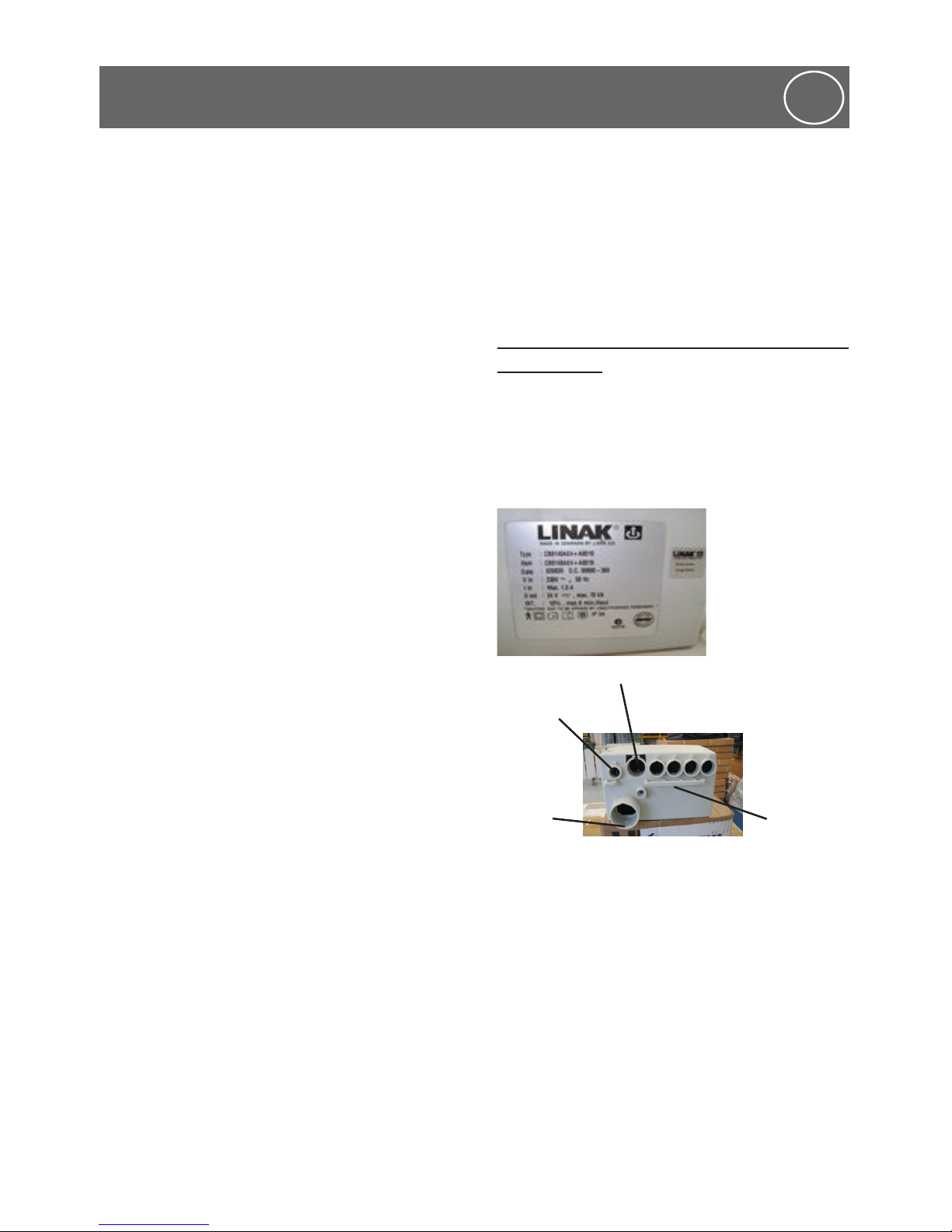
ELECTRICAL COMPONENTS
The corresponding replacement parts can be
obtained from Human Care. When ordering
please specify – TYPE & ITEM. The necessary
details are found on the type plate (as shown
below) on each electrical component.
Safety information on replacing electrical
components
This is a Class 2 electrical product.
CAUTION! Before commencing any work
on electrical equipment, always unplug
the mains cable from the electrical socket.
battery
backup
Handset
Actuators
Mains
Any work and/or repairs to the electrical
equipment may only be carried out by service
engineers, qualified technicians or authorised
electricians in compliance with all the relevant
country of use safety standards.
All electrical drive system components
(actuators, handset, and control box) are
maintenance-free and must not be opened.
In the event of a malfunction, the
corresponding component must always be
replaced in full.

www.humancaregroup.com
5
2. Maintenance
ENG
When replacing individual components,
always ensure that the plugs, outfitted with
undamaged O-rings (seals), are inserted into
the control unit as far as possible. Only then
can reliable sealing and perfect operation be
guaranteed.
The component plugs are connected to the
corresponding port in control box. To prevent
the plugs from inadvertently disconnecting,
they are secured with a locking device. When
necessary, this device can be carefully lifted off
using a screwdriver. The locking device must
always be properly refastened.
Checked OK Not ok Description of fault
Visual check of the electrical components
Handset cable Damage, routing
Mains cable Damage, routing
Visual check of the mechanical components
Mattress Platform is parallel to
floor (ie level)
Damage
Bolts, fasteners, screws Check & tighten regularly
Chassis Damage, deformations
Check for rust or corrosion. Damage
Castors Damage
Bed Extension Damage
Performance check of the electrical components
Backrest Adjustment, secure
retention
Platform Hi/Lo Adjustment, secure
retention
Battery Backup ( if fitted) Check fully charged &
operational
Accessories (eg: Self Help Pole,
side rails)
Fastening, damage
Signature of the Inspector: Name of Inspector:
Inspection result: Date:
66
www.humancaregroup.com
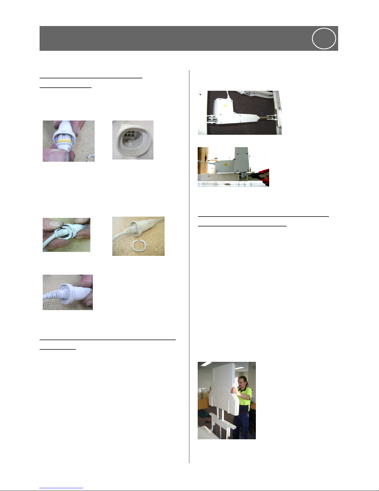
How to fit a mini fit plug when
assembling bed
Pic 1. Lightly lubricate seal on the plug and
insert firmly into the socket ensuring that the
key and keyways are aligned (Pic 2.)
Pic 1. O ring seal
Pic 2 keyway
Pic 3. Fit the plastic circlip using a small flat
blade screwdriver and ensure that the two
locking tabs lock into the slots of the socket.
Pic 3
Pic 4 Locking
Pic 5 Locking slot
How to remove an Actuator –Kneebreak
& Backrest
Raise bed to a comfortable working height.
Remove minifit plug using a small flat blade
screwdriver to release the plastic circlip locking
tabs and separate the male and female mini fit
plug (see pic 1 below)
Remove actuator circlip washer and pin at the
bottom of the actuator only while supporting
the weight of the actuator (with chocks) remove
circlip washer and pin from the other end.
Reverse these steps to replace or install an
actuator.
pic 1
Pic 2
How to remove main bed lift actuators
(Hi/Lo) Head and foot end.
• Pic 1 Remove plastic inner cover by lifting up
and out (not fastened).
• Pic 2 Lower pedestal end onto two blocks
of timber (not supplied) approximately 500600mm in length.
• Remove P clips (cable retainers) with a
Phillips head screw driver.
• Pic 3 Remove circlip and pin from base of
actuator anchor point
• Remove circlip and pin from top of actuator
anchor point.
• Reverse these steps to install or replace an
actuator.
Pic 1
3. How to fit and remove
ENG
 Loading...