

human care FloorLine-i, FloorLine-i Plus, 90303, 90500, 90509 User Manual
...
FloorLine-i Plus/FloorLine-i
User Manual/ Bruksanvisning/
Benutzerhandbuch / Gebruikshandleiding

2
www.humancaregroup.com
Content
User manual
1. Symbols 4
2. Labels 5
3. Technical Specifications 6
4. Product description 7
5. Intended Use 10
6. Optional Accessories 11
7. Safety Advice 16
7. Safety Advice 17
8. Assembly/Disassembly 17
9. Operation Instructions 23
10. Maintenance and service 30
11. EMC table 32
12. Trouble shooting 35
13. CE Mark 36
14. Recycling 36
15. Spare parts 36
Bruksanvisning
1. Symboler 38
2. Märkning 39
3. Tekniska specifikationer 40
4. Produktbeskrivning 41
5. Avsedd användning 44
6. Tillbehör som är tillval 45
7. Säkerhetsanvisningar 50
8. Montering/demontering 51
9. Användarinstruktioner 58
10. Underhåll och service 65
11. EMC-tabell 67
12. Felsökning 70
13. CE-märkning 71
14. Återvinning 71
15. Reservdelar 71
Benutzerhandbuch
1. Symbole 72
2. Schilder 73
3. Technische Daten 74
4. Produktbeschreibung 75
5. Verwendungszweck 79
6. Sonderzubehör 80
7. Sicherheitshinweise 86
8. Montage/Demontage 88
9. Bedienungsanleitung 94
10. Wartung und Service 104
10. Wartung und Service 105
11. EMV-Tabelle 105
12. Fehlersuche 110
13. CE-Kennzeichnung 111
14. Recycling 111
15. Ersatzteile 111
Gebruikshandleiding
1. Symbolen 113
2. Labels 114
3. Technische specificaties 115
4. Productomschrijving 116
5. Bedoeld gebruik 120
6. Optionele accessoires 121
7. Veiligheidsadviezen 126
8. Montage/demontage 128
9. Bedieningsinstructies 134
10. Onderhoud en service 143
11. EMC-tabel 145
12. Fouten opsporen 148
13. CE Markering 149
14. Recycling 149
15. Reserveonderdelen 149

www.humancaregroup.com
3
Human Care beds are designed & manufactured to provide many years of safe operation and use,
when operated in accordance with these instructions.
Human Care would like to thank you for the confidence that you have placed in us and our products, in
deciding to purchase this FloorLine-i Plus bed. We are sure that your investment in this high quality and
durable product will provide you with many years of excellent, cost-effective service.
• Each bed has been tested for safety and functionality, and has let the factory in perfect condition.
• This User Manual informs you, as the operator, and your users, about all product features, complete
assembly and all operating functions necessary to ensure ease of operation, and safe handling of
this bed in its normal and expected environment.
• You should therefore also regard this User Manual, as a practical reference book, to be kept near the
bed and readily available at all times, for anyone involved in its use or operation.
• We wish you and those using the bed, every success in looking after your patients, residents or
guests in a safe, comfortable and mulifuncional bed.
o
is a warning triangle used for situations which require extra care and attention.
CAUTION!
Do not assemble or operate the bed, before reading this manual, as personal injury or
damage to product may occur!
Please contact Human Care in the event of any uncertainties or questions.
FloorLine-i Plus/FloorLine-i
User Manual – Part no. 90500-90509, 90300-90303
ENG

4
www.humancaregroup.com
1. Symbols
ENG
NOTE!
This instruction guide contains important
information for the user of the product. All who
use the product should review and completely
Used in the User Manual, Bed Labels & Packaging
Catalogue Number
Caution - Consult Accompanying Documents
Caution - Pinch Point - Take Care of Hand Placement/Position
Class 2 Electrical Protection - Double Insulation
Conformity with the essential health and safety requirements of the European
Directives
Consult - Instructions For Use
Date of Manufacture
Heat Limitation
Humidity Limitation
Manufacturer
Maximum User Weight
Not for General Waste
understand and adhere to the contents of
the instruction guide.Remember to keep the
instruction guide in a place where it is always
available to those using the product.
www.humancaregroup.com
5
Product should be kept dry
Safe Working Load
Serial Number
Type B - Equipment Providing Protection against Electric Shock
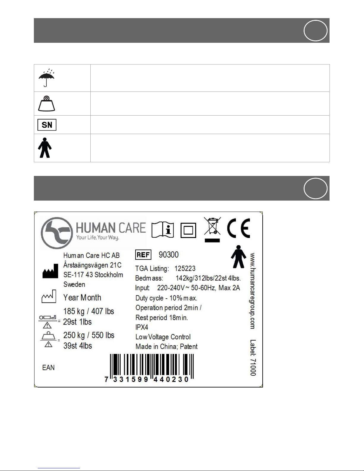
2. Labels
ENG
1. Symbols
ENG
Label
(Only sample.)
The label is placed
on the lower left
head end of the bed
pointing outwards.

6
www.humancaregroup.com
3. Technical Specifications
ENG
Nominal Specifications (mm/inch - kg/lbs/st)
Mattress Platform Length (Standard) * 2000 mm / 78¾”
Mattress Platform Length (with Extension Kit) * 2175 mm / 85½”
Overall Bed Length (Standard-Extended) * 2325 mm - 2500 mm / 91½” - 98½”
Mattress Platform Width 900 mm / 35½”
Overall Bed Width 925 mm / 36½”
Mattress Platform Height Adjustment Range 99 mm / 4” - 799 mm / 31½”
Bed Base Weight FloorLine-i Plus: 85 kg / 187¼ lbs / 1337 st 7 lbs
FloorLine-i: 84 kg / 185 ¼ lbs / 1323 st 3 lbs
Mattress Platform Weight FloorLine-i Plus: 55 kg / 121¼ lbs / 866 st 1 lbs
FloorLine-i: 54 kg / 119 lbs / 8 st 7 lbs
Overall Weight of Bed ** FloorLine-i Plus: 150 kg / 330 lbs / 23 st 8 lbs
FloorLine-i: 150 kg / 330 lbs / 23 st 8 lbs
Bed Operating Output Voltage Max. 24 volts DC
Power Input Voltage / Frequency - 90500-90503, 90504, 90300-90301,90303, 90504-90507,
90509: 220-204 V, 50Hz
- 90503, 90302, 90508: 110-120 V, 60 Hz
Audible Acoustic Energy < 65dB
Duty Cycle—Operating Time 10% max. 2 min operation / 18 min rest.
Electrical Protection Classification - 90500, 90502, 90504, 90300, 90301 90303, 90505, 90506,
90509: Class 2 - Double Insulation
- 90501, 90503, 90302, 1 90507, 90508: Class 1 - Earthed
IP Rating IPX4
Mains Power Amps - 90500-90503, 90504, 90300-90301, 90303, 90505, 90506,
90509: Max 2 Amps
- 90503, 90302, 90507, 90508: Max 4 Amps
Mattress Platform Panel Angles:
Backrest
Thigh
Knee
Calf
Trendelenburg / Reverse Trendelenburg
70°
45°
110°
25°
18°
Safe Working load (SWL): Mattess Base & Bed 250 kg / 550 lbs / 39 st 4 lbs
Maximum User Weight (MUW) 185 kg / 407 lbs / 29 st 1 lbs
* Beds are shipped normally in standard length (sleeping space of 2000 mm/78¾” x 900mm/35½”), But
can be extended to 2175 mm / 85½”) with the addition of an Optional Extension Kit and Bolster.
** Not including accessory weight.
All measurements are subject to commercial manufacturing tolerances. (E & OE)
The bed serial number is located on a silver label, on the side of the top beam, under the backrest
panel at the head end of the bed, on the same side as the green castor. This number is required when
requesting service, spare parts or ordering additional accessories. Record this number in the space
provided, on the Front Cover and Check List.
www.humancaregroup.com
7
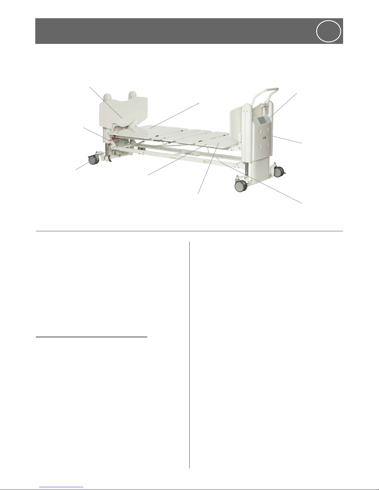
4. Product description
ENG
Electric Backrest
Attendant
Control
Keypad (only
FloorLine-i
Plus)
Electric Kneebreak
CPR Emergency
Quick Release
Lever (only
FloorLine-i
Plus)
Removable Head
& Foot Boards
Foot End
Pedestal
Lower
Beam - Bed
Base
Mattress
Retainer - useful
to hang handset
Control
Box
The product contains of:
• bed base
• mattress platform
• head and foot board
• hand control
• mattress retainers
• plastic bag with User manual and allen key
4.1 Instructions for the operator:
Please pay attention to your obligations, as the
operator, in order to ensure the permanently
safe operation of this medical product,
minimising risks to the patient, user and/or third
parties.
Any piece of technical equipment, electrical or
otherwise, can prove hazardous, if not properly
operated and maintained in accordance with its
User Manual. It is recommended that you are
informed of all operations and perform regular
maintenance on equipment.
Definitions:
Operator (e.g.: clinic, hospital, hospital
management, nursing home), is every natural or
legal person with property rights over the bed
(including when subject to hiring, rental or lease
arrangements).
Responsibility for the safe operation of
this bed lies with the operator.
User
(specialist medical staff, nurses, doctors,
attendants and care staff) are persons who, on
the basis of their training, experience or thorough
instruction, are entitled to operate the bed on
their own responsibility, or to carry out work
on it, or who have received instruction in the
handling of this bed. Furthermore, they are able
to recognize and avoid possible hazards as well as
assess the clinical condition of the patients.
Patient, Resident or Guest
In this manual, a patient is described as any
person being ill, infirm, disabled, in need of care,
or otherwise occupying this bed.

8
www.humancaregroup.com
5. Battery Backup allows for off-mains
emergency operation for up to 15 minutes
under a normal load. To ensure long battery
life, the bed should be connected to mains
power, at all possible times. Do not exceed
the duty cycle.
6. Electrical protection of wiring and cords will
differ between Class 1 (Earthed) and Class 2
(Double Insulation) Beds.
4.3 Standard features
The backrest is a large mattress panel that raises
from a supine position to an upright position,
convenient for sitting, which allows a patient
to enjoy the flexibility of changing to multiple
positions for comfort and health.
Kneebreak
The kneebreak is a double mattress panel
that splits as it electronically lifts or bends
the patient’s thigh and calf at the knee, thus
combining functionality and comfort for both
the patient and carer.
Auto-Contour
A Handset feature that uses one button to adjust
both Backrest & Kneebreak simultaneously, into
a cardiac chair position, even when the bed is in
it’s lowest height position.
Battery Backup
The Battery Backup allows for operation of the
bed, should mains power fail, or if the bed is
being operated temporarily away from mains
power. The battery can operate for a total
time of up to 15 minutes under a normal load.
Make sure not to exceed the duty cycle (2 min
operation, 18 minutes rest).
To ensure long battery life, the bed should be
connected to mains power, at all possible times.
If the backup battery becomes flat, raising
lowering functions will slow down or cease. A
replacement should be ordered and fitted.
4. Product description
ENG
Each time the bed is allocated, it is
recommended that the patient is instructed in
all the functions that are important for him/her,
by the operator or user.
4.2 Structural Design
Mattress Platform: The mattress platform is
a four panel design, divided into a back rest,
a seat section and a double panel kneebreak.
The mattress base can be horizontally adjusted
in height. The bed can be adjusted to headlow (Trendelenburg) or feet-low (Reverse
Trendelenburg ) positions.
Chassis:
The chassis is constructed of welded steel.
It features four individually locking castors
that include: 3 grey Brake Castors and 1 black
Directional Lock Castor.
Electrical Adjustment System:
The electric adjustment system comprises:
1. The Backlit Handset for patient control of
the bed’s positions. It is a ‘remote-control’
attached via a curly cord, to the bed’s control
box; consisting of a robust, easy-care, washdown plastic casing with a backlit membrane
keypad.
2. The Attendant Control Keypad
(only for the FloorLine-i Plus bed)
(ACK) is located at the foot end of the bed. It
is used to lock out and replace the handset,
for nurse convenience. It comprises a washdown membrane keypad, with indictor lights.
3. Actuators & Junction Boxes for adjusting and
controlling the backrest, kneebreak and the
bed heights.
4. The Linak Open-Bus Central (only for the
FloorLine-i Plus bed) Control Box Unit and
Battery Backup are located underneath the
Head End Cover. They contain a low-voltage,
safe 24V transformer. The electric motors/
actuators, the battery backup, the ACK and
handsets (24V) are connected to the Control
Box and Junction Boxes via dust and moisture
proof plugs and cords/cables.
www.humancaregroup.com
9
4. Product description
ENG
Batteries in good condition will normally
recharge in 12 hours or overnight when the bed
is plugged back into the mains power supply.
Extended periods without mains power will
make the batteries unable to be recharged or
operate at all. A replacement unit will need to
be ordered and fitted.
Backlit Handset (only for the FloorLine-i Plus bed)
The Backlit Handset permits patients to control
and adjust their own bed, to different positions,
to suit their changing comfort levels throughout
their stay in bed. The soft lighting feature allows
a patient the convenience of night-time use,
without other lights.
Cardiopulmonary Resuscitation (CPR) Quick
Release System (only for the FloorLine-i Plus bed)
The CPR emergency procedure (combined
rescue breathing and chest compressions) is
used on a patient in cardiac arrest. Firstly, using
either one of the CPR Quick Release Levers,
located under either side of the backrest, the
backrest can be quickly flattened, mechanically.
Secondly, the CPR button on the ACK, will also
electrically flatten the bed into the defined
(country specific) CPR position. The bed ordered
will be country-appropriate!
Attendant Control Keypad (ACK)
(only for the FloorLine-i Plus bed)
The Attendant Control Keypad can be used in
addition to the Backlit Handset to adjust the bed
movements. It allows a nurse/carer to control
the bed’s positioning operations and can limit
the patient’s control of the bed, improving
comfort and safety with it’s handset lock out
function.
Push Handle
(only for the FloorLine-i Plus bed)
A multi position push handle is fitted to the foot
end of the bed to assist carers with easy bed
manoeuvrability. For the FloorLine-i the push
handle is an optional accessory.
Patient Egress Light
(only for the FloorLine-i Plus bed)
The bed is fitted with two under bed lights
located on the under side of the Junction
Boxes either side of the bed. Soft illumination
around the bed provides extra safety and
comfort. Controlled using the backlit handset,
the lights do not interfere with other patients
and eliminate the need for wall-mounted night
lights.
4.4 Application Environments
The FloorLine-i bed is applicable to: Environment
2, 3 and 4.
The FloorLine-i Plus bed is applicaple to:
Environment 1, 2 and 3.
Explenation of environments:
Environment 1:
Intensive/critical care provided in a hospital
where 24 hour medical supervision and constant
monitoring is required and provision of life
support system/equipment used in medical
procedures is essential to maintain or improve
the vital functions of the patient.

10
www.humancaregroup.com
5. Intended Use
ENG
These beds are designed for use in hospital care
and long -term care facilities, for the purpose
of providing comfort and quality care for any
person being ill, frail, disabled, or in need of
special care.
These beds may only be operated by persons
who have received instruction in its safe
operation. These beds may only be operated
under the conditions of duty described in this
manual.
Environment 2:
Acute care provided in a hospital or other
medical facility where medical supervision and
monitoring is required and ME EQUIPMENT
used in medical procedures is often provided to
help maintain or improve the condition of the
PATIENT.
Environment 3:
Long-term care in a medical area where
medical supervision is required and monitoring
is provided if necessary and ME EQUIPMENT
used in medical procedures may be provided to
help maintain or improve the condition of the
patient.
Note: This includes use in nursing homes,
rehabilitation and geriatric facilities.
4. Product description
Environment 4:
Domestic Care: Ergonomic requirements are
normative Care provided in a domestic area
and ME EQUIPMENT is used to alleviate or
compensate for an injury, disability or disease.
NOTE :This excludes use in all other application
environments (e.g. nursing homes, rehabilitation
and geriatric facilities) when a medical bed is
purely designed for application environment 4.
Any other use shall be regarded as
noncompliant with safe, legal and correct
usage and may invalidate warranty.
ANY OTHER USE SHALL BE REGARDED AS
NONCOMPLIANT WITH SAFE, LEGAL AND
CORRECT USAGE AND MAY INVALIDATE
WARRANTY.
The head and foot end pedestal covers of the
beds are ABS plastic. The bed also comprises
electrical componentry and cables. All the
surfaces are non-harmful, upon coming into
contact with the skin.
www.humancaregroup.com
11
Picture 1
Picture 2
Picture 3
Picture 4
6. Optional Accessories
ENG
It is important that only Human Care
accessories are fitted to Human Care
beds, as any incompatible accessories can
create hazards.
Mattresses
The medical bed is designed for use with specific
mattress types and dimensions measuring
1980mm (78”) long by 900mm (35”) wide and
125mm (5”) deep. It is imperative to use this
size mattress to reduce the risk of entrapment
and falls.
o
Incompatible mattresses can
create hazards.
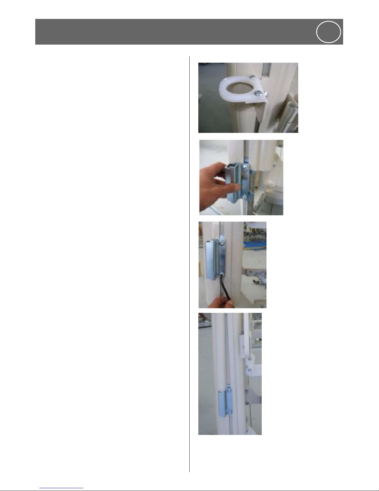
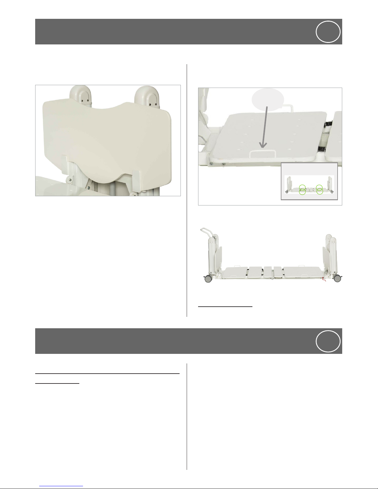
Self Help (SH) Pole and how to fit a Self Help Pole
The Self Help Pole is intended to assist a patient
moving within the confines of the bed. It is not
to be used for any other purpose. The Self Help
Pole has a safe working load of 75kg (165lb).
The fittings for the Self Help Pole are fitted into
the head end leg extrusion above the green
directional castor.
1. The fittings are designed to slide up into the
extrusion slot.
2. Pic 1 Identify top fitting as this is placed first.
3. Install using bolt and nut assembly provided.
Fit top tab of bracket into the aluminium
extrusion slot. Push the bracket up inside
the slot until there is no further movement.
Slide the nut assembly into the extrusion slot
from the bottom of the extrusion; push nut
assembly to meet the top bracket and firmly
tighten with bolt provided.
4. Pic 2. The lower bracket can then be fitted
into the slot from the bottom.
5. Slide Self Help Pole Nut plate Bracket up into
accessory slot in pedestal extrusion.
6. Pic 3 Tighten the hex head bolts. Only Human
Care self help poles will fit the beds Pic 4
shows final position for lower bracket.
12
www.humancaregroup.com
Intravenous (IV) Pole and Fitting an IV Pole
Adjustable IV Poles can be fitted to both ends of
the bed.
It is important to only use Human Care IV
Poles, as any incompatible IV poles could cause
damage and/or injury. The safe working load of
the IV Pole is 7kg (15lb).
The bed is fitted with four brackets for IV Poles.
They are located at each corner of the bed,
behind the head and footboards.
Note: Only Human Care IV Poles will fit
the beds.
Care Assist Rails
Designed to assist patients safely in and out of
bed, it is ergonomically designed and low profile
to avoid feeling restricted or restrained.
Wall Bumper Bar:
The Wall Bumper Bar protects the head end of
the bed. This bumper bar is fitted to the lower
cross beam between the castors.
Oxygen Bottle Holder
A bracket holds a ‘C-size’ Oxygen Bottle
conveniently to the FloorLine-i Plus and
FloorLine-i Bed.
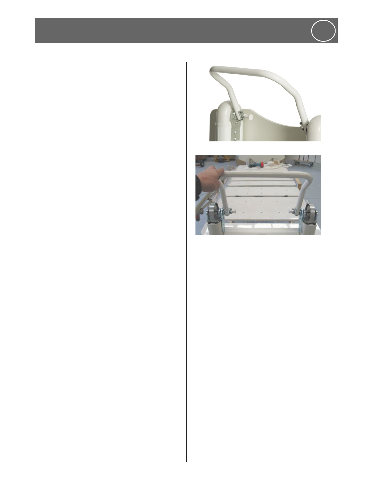
Push handle and how to fit Push Handle
1. Remove footboard, both end caps and the
‘snap latch’ lug
2. Remove the small plastic strips on the inside
of both pedestal legs.
3. Position the push handle using the bottom
two screw holes and secure with 3 x 15mm
button head screws and washers
4. Secure 1x25mm screw through the ‘snap
latch’ lug back into its original position.
Replace end caps and footboard.’
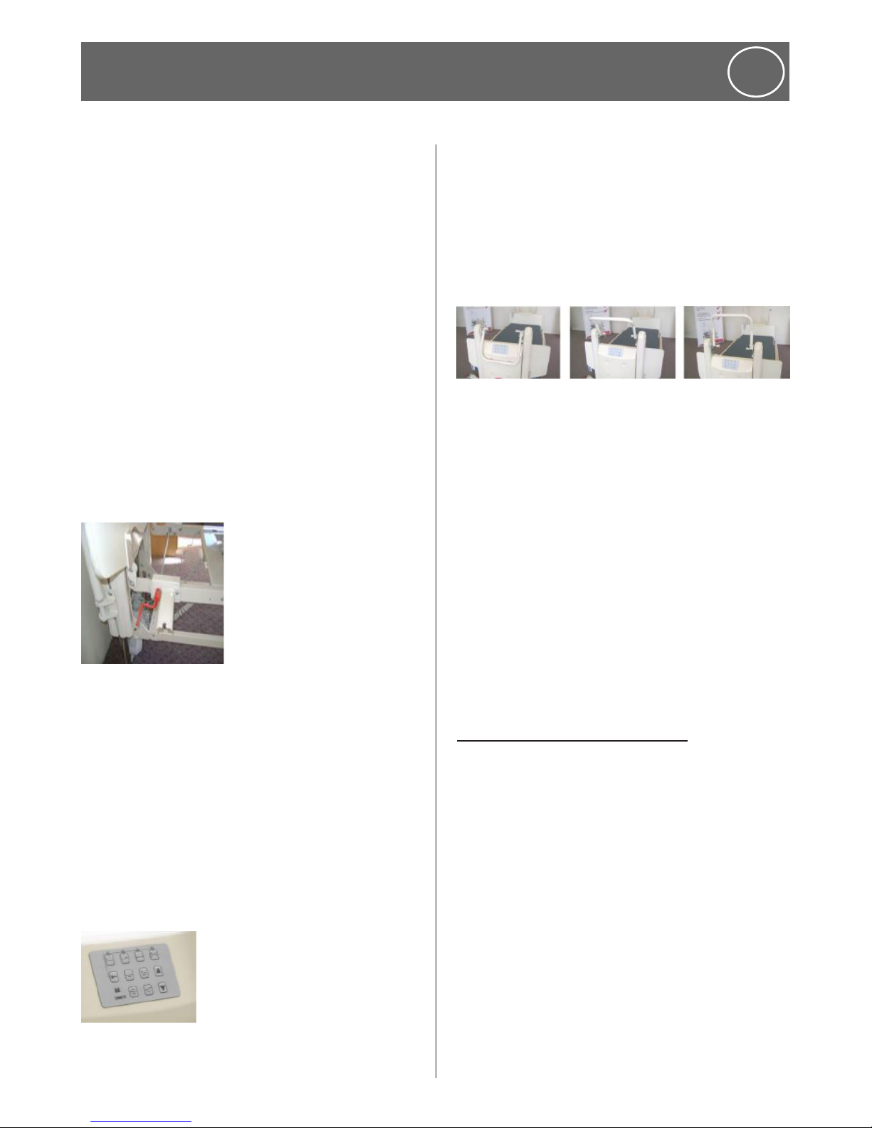
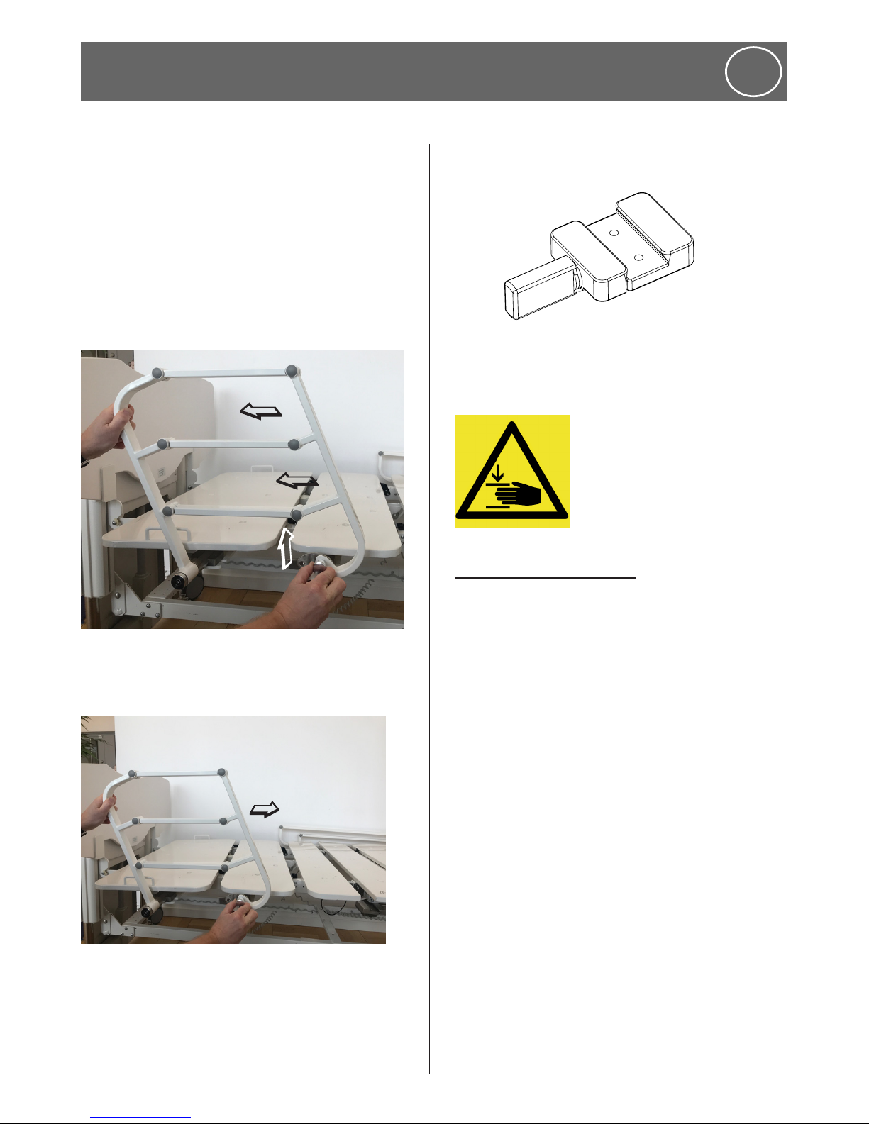
6.1 Side rails and using the side rails
Human Care recommends against the use of
side rails however Human Care is aware that in
some cases, side rails can be expected for care.
Only authentic Human Care side rails should be
fitted to a Human Care true floor-level bed, as
any incompatible side rails may cause damage
and/or injury.
Human Care offers side rails in three different
versions; ¾ length, ½ length and as a split side
rail; ½ plus ¼ length.
6. Optional Accessories
ENG
www.humancaregroup.com
13
o
Make sure that the knobs for tightening
the side rail is horizontal and not vertical.
If pointing downwards it will risk breaking
when the bed is lowered to floor level.
Collapsing the side rails:
Raising the side rails:
Removing the side rails:
o
Caution! pinch point.
6.2 Fitting the side rails
Please see separate assembly instruction.
6. Optional Accessories
ENG
6
7
5
8

14
www.humancaregroup.com
6. Optional Accessories
ENG
6.3 Extension Kit- extending the bed
The standard length of the FloorLine-i Plus and
FloorLine-i bed’s mattress platform is 2000mm
(783/4 ”) measured internally between the head
and footboards.
An optional Bed Extension Kit may be
purchased separately, that will lengthen the
bed, by 175mm (7 ”) to 2175mm (851/2 ”) to
accommodate taller people.
Requirements:
• Two qualified assembly persons
• A mains power outlet/power-point
• Work bench
• 2. 3mm, 4mm & 5mm Allen Keys
• 10mm & 13mm Spanner/Socket Wrench
• Needlenose Pliers
• Small flat screwdriver
Extension kit contents CONTENTS
• 2 x Extension Brackets
• An Extension Mattress Platform Panel (F8)
• 4 x Extension Panel Platform Bolts/Nuts
• Full instructions to fit the extension.
Preparation
1. Confirm all the kit contents.
2. Remove all bedding and accessories.
3. Test bed functions & complete a visual
inspection. Report any faults/damage.
4. Clean the bed thoroughly
5. Ensure sufficient protected floor space for
installation.
6. Remove the Head/Footboards, and safely set
aside.
7. Connect mains power cable to power outlet.
8. Ensure all castors are locked for safety.
9. Using the handset, flatten/neutralize all
the bed positions (backrest, kneebreak,
Trendelenburg/reverse).
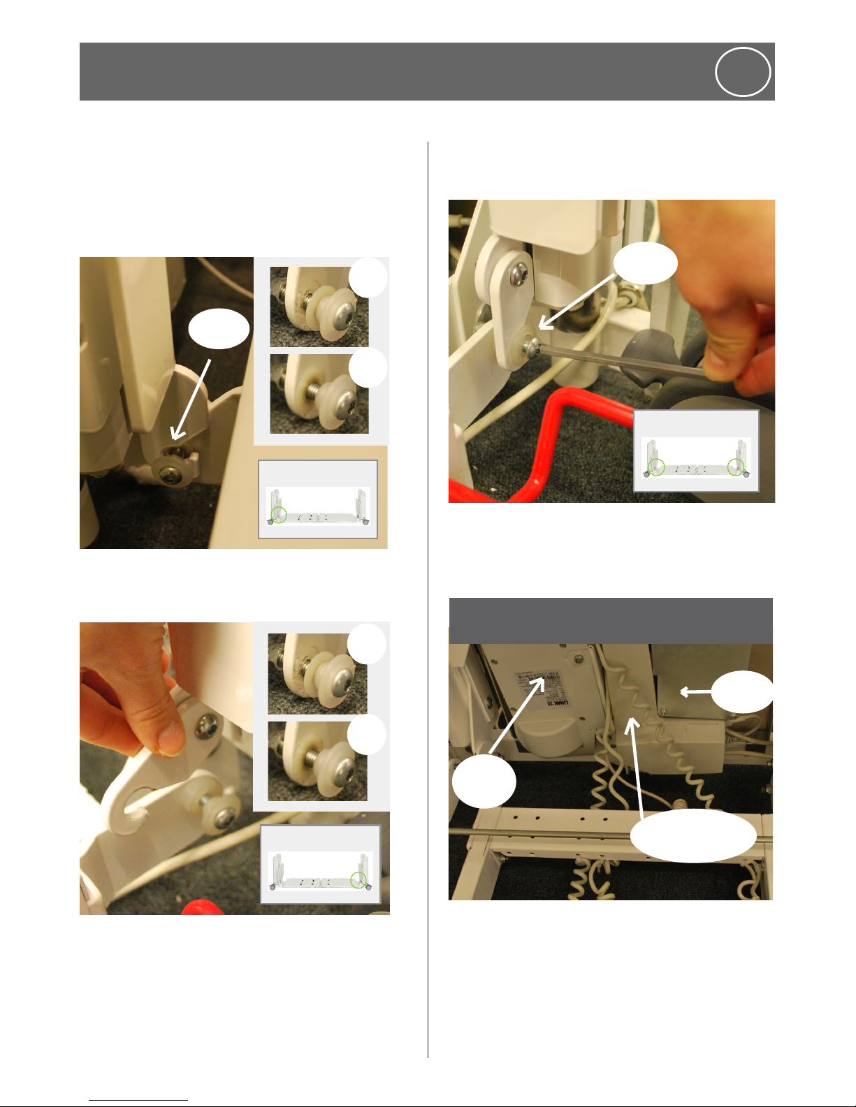
Disconnect cables
1. To allow better access to cables and bolts:
• Raise the bed to its maximum height and
• Lift backrest and foot-end panels.
2. Release the backrest and kneebreak cables
from the plastic retaining clips (1 backrest cable
clip/3 kneebreak cable clips) that secure them
to inside of the mattress platform frame.
3. Disconnect the kneebreak (long) cable from
its mini-fit actuator plug, by first removing
the plastic retaining clip with a small flat
screwdriver.
4. Set aside the plastic retaining clips and keep
the cable safe.
5. Repeat above step for backrest (short) cable.
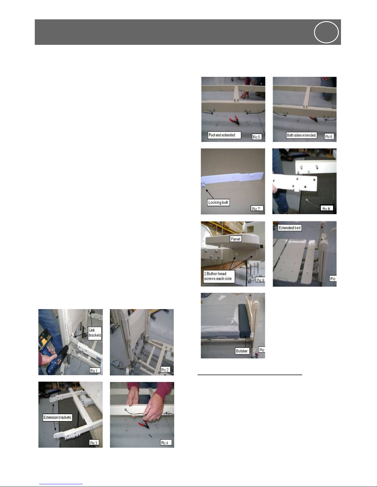
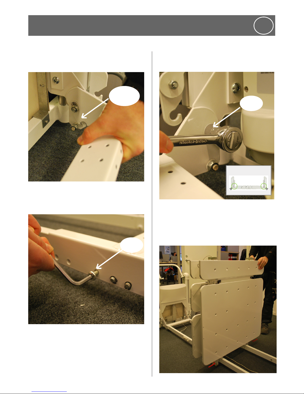
6.4 Fitting the Extension Kit
The lower beam has a built in adjustment, to
allow the Extension Kit to be fitted to the top
beam of the mattress platform.
1. Confirm all the kit contents.
2. Remove the Head & Foot Boards.
3. Release the Backrest & Kneebreak cables from
the actuators, by removing the plastic circlip
in the connector.
4. Loosen the mattress platform locking bolts
with an electric drill (Pic 1).
5. Swing the link brackets away at the head end,
then lower the mattress platform onto the
lower beams at head end (Pic 2).
6. Using two people, remove the mattress
platform and carefully place it on a work
bench or table (Pic 3).
7. Remove the 2 circlips at the foot end of the
lower beam saddle, of the bed base, then
remove all 4 pins (Pic 4).
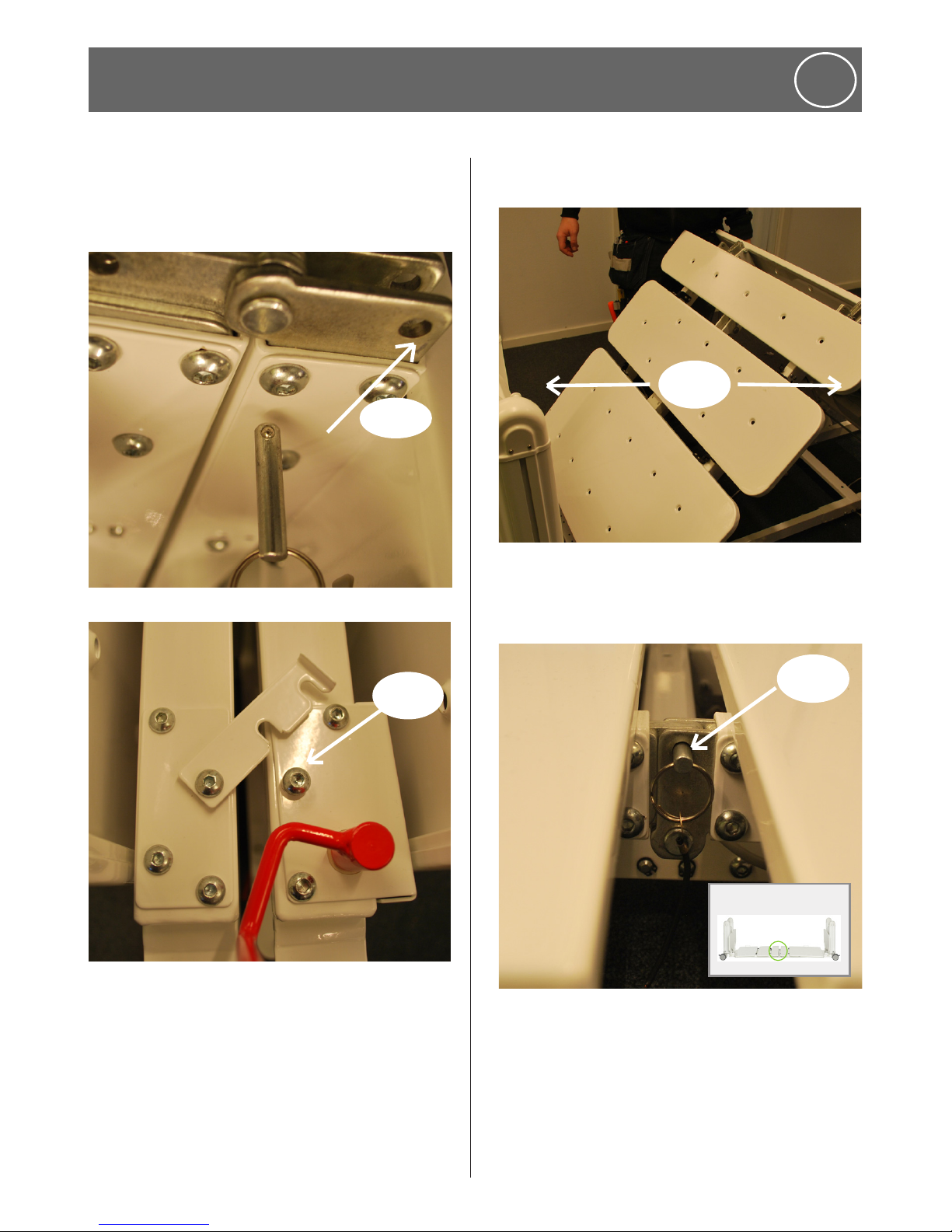
8. Extend the lower beams and replace the 4
pins in the outermost holes, then replace the
circlips (Pic 5).
15
www.humancaregroup.com
6. Optional Accessories
ENG
9. Remove the 2 circlips on the head end of the
lower beam saddle and then remove all 4 pins
(The lower beams are now extended) (Pic 6).
10. Remove the mattress platform locking bolts
and fit them to the extension brackets (Pic 7).
11. Remove the mattress platform standard
brackets, at the foot end and replace them
with the extension brackets. Note that the
support tab sits under platform (Pic 8).
12. Fit the extension panel with the button head
screws and Nyloc nuts (Pic 9).
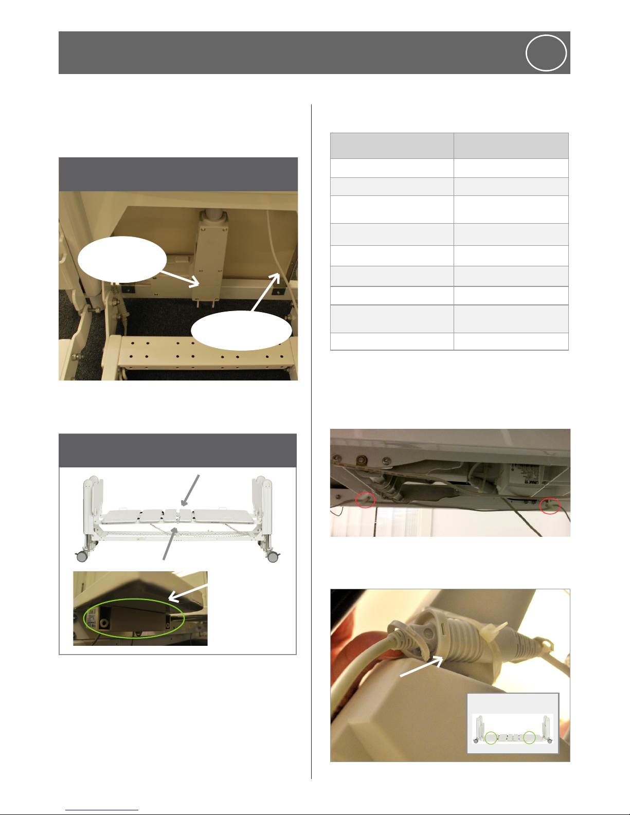
13. Using 2 people, replace the extended
mattress platform, foot end first, ensuring
that the nylon bushes are in the hooks - Do
not over tighten locking bolts (Pic 10).
14. Replace the backrest and kneebreak cables
into the actuator connectors.
15. The Mattress and Bolster can now be placed
on bed (Pic 11).
16. Check all bed functions.
NOTE: The standard length beam brackets
should be kept, so that the bed can be
returned to it’s standard length.
6.5 Removing the extension kit
To remove an Extension Kit from a bed, follow
the above instructions in reverse.

www.humancaregroup.com
16
7. Safety Advice
ENG
7.1 Safety Symbol
In this manual the adjacent safety warning
symbol is shown as:
o
This safety symbol does not replace all the
written safety advice. You are instructed
to read the safety advice and follow it
precisely.
7.2 Safety advice for the operator
With the aid of this manual, which must be
handed over together with the bed, you must
ensure that every user is instructed in the safe
operation of the bed before it is put into service
for the first time.
Draw every user’s attention to the possible
hazards that can arise if the bed is not used
properly. This applies in particular to using the
electrical drives and side rails (if fitted). Human
Care strongly advises against the use of side rails.
o
Incompatible side rails can
create hazards
• Pay attention to your obligations in order to
ensure the permanently safe operation of
this medical product to minimise all risks to
the patient, user and/or third parties.
• If the bed is in long-term use, it is important
after a reasonable period of time, to test all
of the functions, and to check for functional
and visual damage.
• Regular preventative maintenance is the
Operator’s responsibility.
• Only allow this bed to be used by persons
who have been instructed in its safe
operation.Make sure that stand-in or
temporary staff are sufficiently well
instructed in the safe operation of the bed.
7.3 Safety advice for the user
• Make sure that the operator instructs you in
the safe operation of this bed.
• When a patient’s condition could lead to
patient entrapment, the mattress platform
must be left in the flat position.
• Each time, before using the bed, check that it
is in perfect working order.
If any damage or a malfunction is
suspected, immediately unplug the bed
from the mains supply, mark the bed
clearly as being “OUT OF ORDER” and
take it out of service.
Make sure that there are no obstacles (eg:
bedside lockers, chairs, hoists, wall mounted
fixtures, or equipment etc.) which could impede
any adjusting or movement of the bed.
o
This bed goes down to the floor,
do not put anything underneath
it at any time!
7.4 Cables and cord safety
To maintain safe function of the bed and any
external components, attention to cord and
cable placement is extremely important.
• Route the mains cable in such a way that
when operating the bed it cannot get pulled,
be cut, or be driven over, or be damaged by
any moving parts.
• When using external electrical equipment,
such as patient hoists/lifts, reading lamps
etc., make sure that the electrical cables
cannot get caught in, or get damaged by,
parts of the bed.
• When not is use, stow the handset in such a
way that it cannot inadvertently fall onto the
floor; and make sure that the cable cannot
get damaged by moving parts of the bed.

17
www.humancaregroup.com
• Before moving the bed, it is important
to raise the mattress platform to at least
200mm (8”) above floor level, then unplug
it from the mains power supply. Stow the
mains cable safely on a suitable handset
holder on the head end pedestal, to ensure
that it cannot trail on the floor.
7.5 To safeguard the patient and
particularly children
Always inform the patient about safe operation
of the bed’s controls. If the patient is unable to
operate the bed safely or free themselves from
potentially dangerous positions, they could be
placed at risk through inadvertent adjustment of
the electrical functions.
• It is recommended that children are never
left unsupervised in a room with the bed.
• Place the handset beyond reach of children
or ‘at risk’ patients, to prevent inadvertently
initiating power adjustments of the bed. Any
adjustments may then only be carried out by
or in the presence of a person instructed in
the proper operation of the bed.
• Always ensure that the mattress platform has
travelled to its lowest position before leaving
an ‘at risk’ patient in the bed unattended.
In this way, you greatly reduce the risk of
patient injury as a result of falling out of bed.
• If a patients’ condition contains a risk of
entrapment, then the mattress platform
should always be left in a flat position.
• Take care with the use of side rails. If the
side rails are raised, there is a risk of limbs
gettng trapped or crushed on adjusting the
backrest or kneebreak. Human Care strongly
recommends against the use of side rails.
7.6 Checks and inspections
Make sure to follow mainteance instructions to
ensure safe use ot the bed.
7. Safety Advice
ENG
8.1 Assembly
Requirements
1. Two assemblers
2. A mains power outlet/power-point since the
backup battery may not be fully charged at
time of delivery.
3. 3mm & 5mm Allen Keys
4. 13mm & 17mm spanner/socket wrench
8. Assembly/Disassembly
ENG

www.humancaregroup.com
18
1. Included in the bed delivery: Folded Bed
Base, Attached Handset, mattress retainers,
Head/Foot Boards and folded Mattress
Platform.
2. Ensure all castors are locked for safety. Then
use the 5mm Allen Key, remove the 4 Centre
Saddle Locking Bolts. Two each are located
on either side of the saddle.
Remove
3. Unlock two of the castors on one side and
keep the other two on the other side locked.
On both sides, unlatch the plastic transport
latch that holds the beam against the
pedestal ends.
Unlatch
4. Stand at the side of the pedestal ends, one
person on each side and unfurl the bed
until it´s flat. One person holds still and one
pulls the bed out (on the side with unlocked
castors). Make sure no cables are in the way
when unfoldning the bed!
Unfurl
8. Assembly/Disassembly
ENG
19
www.humancaregroup.com
5. Attach the bolts to it´s position. The bolts
may be a tight fit. Gently lifting the saddle
aids fitting each bolt in.
Lift and fit
bolt in
6. Using the 5mm Allen Key, put back/insert
and tighten the 4 locking bolts into the same
holes on the saddle.
Tighten
8. Assembly/Disassembly
ENG
7. Using the 17 mm spanner, tighten the 8
Nyloc bolts (2 Lower Beam Hinging Bolts and
2 Locking Latch Bolts at each end).
Tighten
8. Place the mattress platform onto the bed
base as in the picture. The backrest panel
(largest panel) shoulde be positioned at the
head end of the bed base.
www.humancaregroup.com
20
8. Assembly/Disassembly
ENG
Remove the two locking lanyard pins from either
side of the centre hinge section/upper beam
saddle.
Remove
9. Unlatch the metal transport latch.
Release
10. Fold out the mattress platform until the
beams are straight.
Fold out
11. Re-insert the 2 locking lanyard pins, to lock
the mattress platform into a flat position.
Insert
21
www.humancaregroup.com
8. Assembly/Disassembly
ENG
12. At the foot end: lift the beams to slot the 2
Platform Bracket’s Fixing-Bolts (Nylon Bush)
into the 2 Pedestal End’s Fixed J-Hooks. Lift
the beams to fully seat the fixing-bolts. The
hook should be placed in between the 2
nylon bushes as in the picture.
Attach
x
a
13. Repeat the steps from picture 14 at the head
end.
x
a
x
14. Using the 5mm Allen Key, firmly tighten all 4
Upper Beam Fixing-Bolts, ensuring that each
bush is correctly located in its J-Hook.
Tighten
15. The cables run from the control box and
battery at the head end side. Image 18-20
only applies for FloorLine-i Plus.)
Battery
Control
box
Actuator head
end pedistal
INFORMATION
www.humancaregroup.com
22
8. Assembly/Disassembly
ENG
16. The cables run from the actuator foot end
pedestal and the attendant control panel at
the foot end side.
INFORMATION
Cable to Attendant
Control Panel
Actuator foot
end pedestal
17. The picture shows the ports in the under
bed light box where the cables should be
inserted.
12345
connection
junction boxes
INFORMATION
18. Insert the cables as in table. Then raise the
bed.
FROM TO
Backrest Actuator Control Box Port 1.
Head End Lift Actuator Control Box Port 2.
Kneebreak Actuator (see
picture 21)
Control Box Port 3.
Foot End Lift Actuator Control Box Port 4.
Under Bed Light Junction # 1. Control Box Port HB
Under Bed Light # 1, Port 1. Under Bed Light # 2, Port 5.
Under Bed Light # 2, Port 1. Attendant Control Panel
Handset Under Bed Light # 2, Port
2 or 4.
Port Plugs Empty Ports
For beds with central locking (90505-90509),
Connect cable89754 (Linak 0964461) to bed
light junction box on left side and secure cables
with clips according to the picture below.
19. Insert the small plastic ring into the cable
both for the backrest actuator cable and
kneebreak actuator cable.
23
www.humancaregroup.com
20. Place the end boards on both sides of the
bed.
21. Attach the mattress retainers on both sides
of the bed. 2 on each side.
Attach
The bed is ready for use!
8.3 Disassembly
Do the assembly instruction in reverse.
9. Operation Instructions
ENG
8. Assembly/Disassembly
ENG
9.1 Before putting this bed into service for
the first time
1. Read through this Instruction Manual
completely.
2. Confirm that the electricity supply and
the wall power-point/outlet/socket are
both compatible with the bed’s voltage
requirements and the bed’s mains supply
cable plug.
3. Inspect the mains supply cable for perfect
condition. Check for any damage in transit.
4. Assemble the bed and attach all accessories.
5. Confirm that all cables and cords are
connected and securely routed out of the way
of all the bed’s moving parts, so they can not
be damaged.
6. Confirm that all nuts, locking bolts, pins and
fasteners are fully engaged and correctly
tightened. Ensure that the battery is plugged
into the control unit.
7. For safety, ensure that all bed wheel castors
are locked unless the bed is being moved.
www.humancaregroup.com
24
8. Test that the bed are all fully functioning and
in perfect working order.
9. Clean and disinfect the bed prior to placing
the mattress and any bedding on the bed, for
first time use.
9.2 Putting the bed into service
1. Confirm wheel castors are locked.
2. Ensure clearance for bed movements.
Provided the above has been complied
with, the bed may now be put into service.
1. Confirm that the wall power switch is OFF (in
countries where this applicable).
2. Plug the mains supply cable into the wall
power-point/socket/outlet.
3. Turn ON the wall switch at the power-point,
(country-determined).
This bed should be connected to the mains
power supply and remain switched on at all
times, to guarantee that the bed’s battery
backup is adequately charged and ready for
operation at any time.
4. Check that the bed has been initialised, is fully
functioning and in perfect working order
5. Confirm that the bed has been cleaned and
disinfected.
9.3 Putting the bed back into service
1. Read and follow the previous two sections
(reading the Instruction Manual, attending to
all safety issues & operation usage).
2. Conduct a complete Maintenance Check for
safe bed functioning and perfect working
order. Especially check for the safe routing
of all cables/cords and clearance for all bed
adjustments.
3. Verify wheel castors are locked.
4. Confirm mains wall power is OFF.
5. Recheck the mains cord/plug for damage
while out of use, push into wall socket.
6. Turn ON the wall switch (in countries where
this is applicable) and leave permanently on,
for charging back-up battery.
7. Confirm bed is cleaned and disinfected.
9.4 The main functions of the bed
The mattress platform has four main panels that
can be adjusted into different positions.
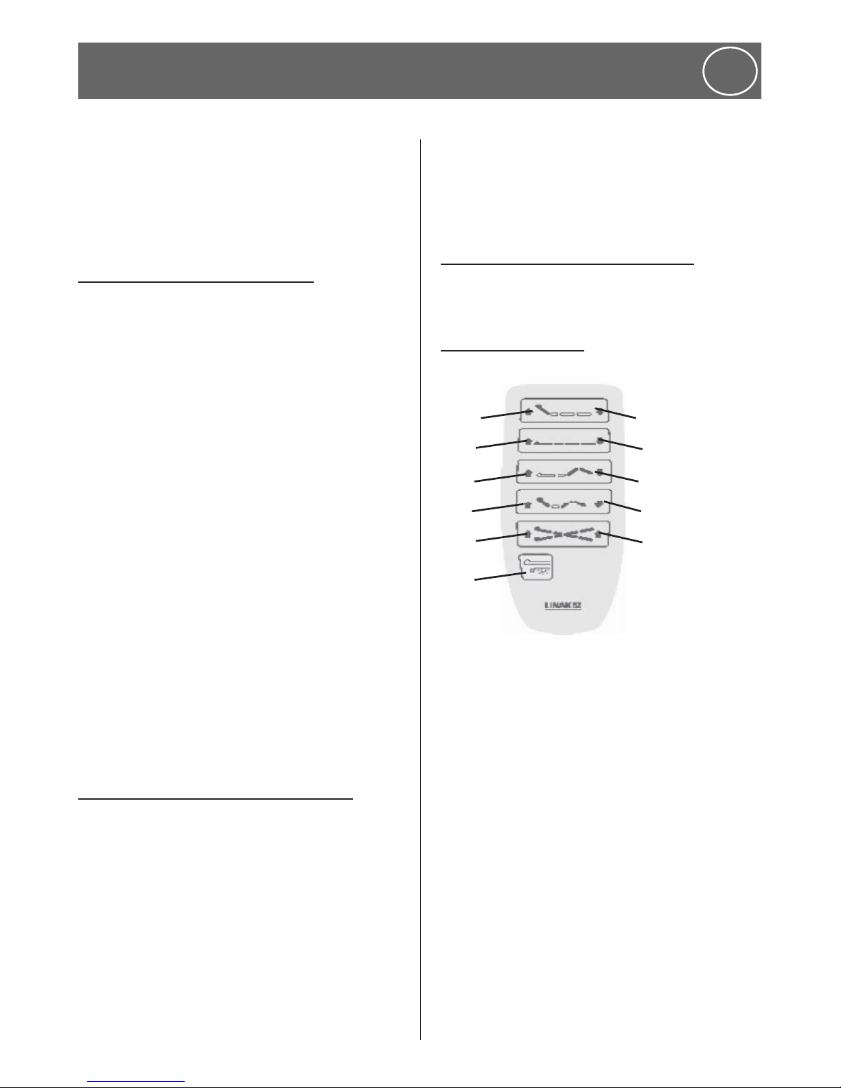
9.5 Backlit handset
FloorLine-i Plus
1
2
3
4
5
6
7
8
9
10
11
1. Back rest down
2. Hi-lo down
3. Knee break down
4. Auto contour down
5. Trendelenburg tilt
6. Back rest up
7. Hi-lo up
8. Knee break up
9. Auto contour up
10. Reverse Trendelenburg tilt
11. Under bed light on/off
9. Operation Instructions
ENG
25
www.humancaregroup.com
9. Operation Instructions
ENG
FloorLine-i
6
8
9
7
10
1
3
4
2
5
1. Back rest down
2. Hi-lo down
3. Knee break down
4. Auto contour down
5. Trendelenburg tilt
6. Back rest up
7. Hi-lo up
8. Knee break up
9. Auto contour up
10. Reverse Trendelenburg tilt
The Backlit Handset is directly connected to the
control box, via a curly cord. Used predominantly
by the patient, each button has a Raise (Left Side)
and a Lower (Right Side) function that adjusts all
mattress platform positions.
• All the buttons (labelled below) should be
explained to the patient.
• When the bed or individual sections of
the bed have reached the desired position
release the button to stop movement.
• Movement in the opposite direction will be
resumed when the appropriate button is
pressed.
• When maximum raised or lowered positions
of mattress base or backrest are reached,
a built-in limit switch will automatically
override the handset button and movement
will stop.
• When not in use, the handset is designed to
clip over the mattress retainers on the sides
of the mattress platform or over the Head &
Foot Boards.
NOTE: If a problem occurs with the handset,
confirm that the correct Initialisation Process
was completed during Bed Assembly.
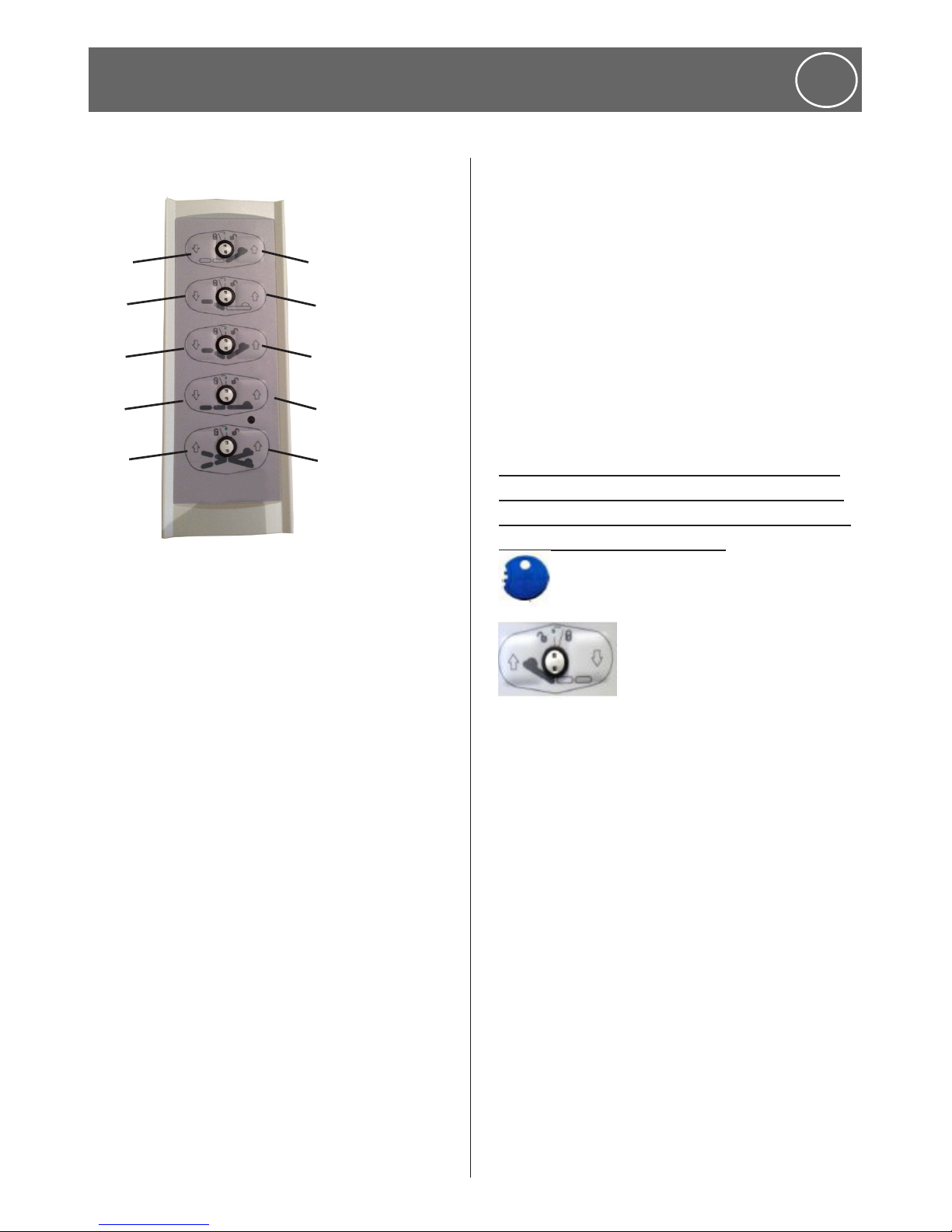
9.6 Lockout (this information is only for
the FloorLine-i bed since the lockout for
FloorLine-i Plus is controlled through the
attendant control keypad.
A small blue plastic ‘lock out key’ is included, to
lock any function on the bed:
1. Insert the key into the two holes in the button
you wish to lock out
2. Gently turn the key from the ‘green’ - 12
o’clock position toward the unlock or
lock symbols at 11 or 1 o’clock positions
respectively.
Gently turn the lockout key in the holes, or key
tabs may break.
www.humancaregroup.com
26
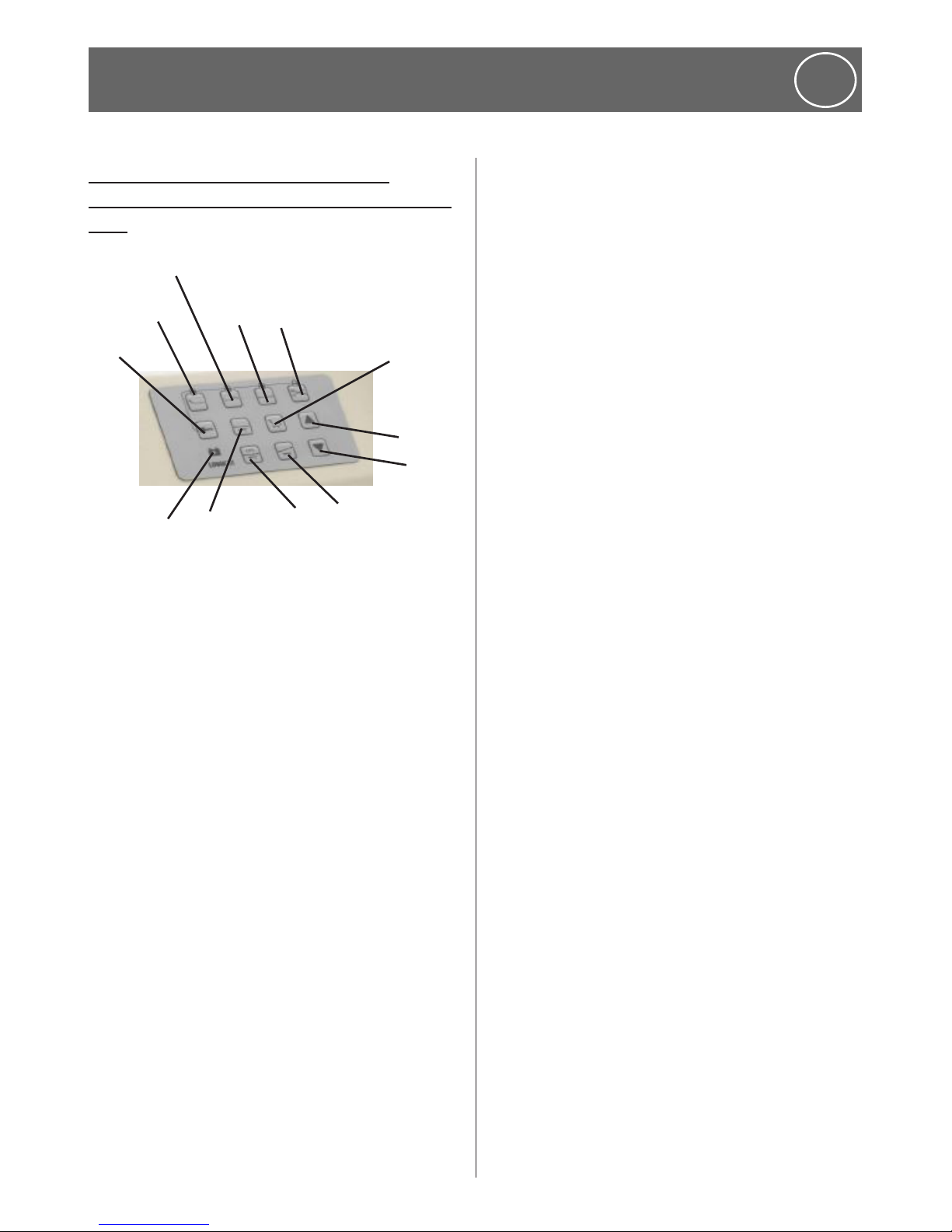
9.7 Attendant Control Keypad (this
information is only for the FloorLine-i Plus
bed)
1
2
3
4
5
6
7
8
9
10
11
12
1: Backrest
2: Kneebrake
3: Hi-Lo
4: Trendelenburg/reverse
5: Auto-contour
6. Raise
7: Lower
8: Single button trendelenburg
9: CPR
10: Level bed
11: Battery charging indicator light
12: Lockout
The Attendant Control Keypad (ACK) can be used
in addition to the Backlit Handset to adjust the
bed movements. It allows a nurse/carer to control
the bed’s positioning operations and can limit the
patient’s control, improving comfort and safety of
high risk patients and limiting guest interference,
with it’s handset lock out function. It is located on
the bed’s foot end.
The raise and lower buttons work in conjunction
with the function buttons. Push both a Function
Button together with the Raise-Button (or the
Lower-Button).
9. Operation Instructions
ENG
Function buttons
Backrest - Press the Backrest button AND the
Raise OR Lower button simultaneously to adjust
the backrest up or down.
Kneebreak - Press the Kneebreak button AND
the Raise OR Lower button simultaneously to
adjust the kneebreak up or down.
Hi-Lo - Press the Hi-Lo button AND the Raise
OR Lower button simultaneously to adjust the
mattress platform height up or down.
Trendelenburg/Reverse Trendelenburg
Press the Trendelenburg/Reverse button AND
the Raise OR Lower button at the same time
to put the bed into Trendelenburg or ReverseTrendelenburg positions.
LOCKOUT - Press any function button together
with the Lockout button to restrict that bed
function. The functions which are locked out will
show a yellow/orange light. To Unlock, press the
function button, again, with the Lockout button;
the light will toggle out.
Level Bed - Press the Level Bed button AND the
Raise OR Lower button, the bed will first take
the position to the highest or lowest height
respectively and then flatten and level the bed
to a flat deck position.
Auto-Contour - Press the Auto-contour button
AND the raise button simultaneously, to put
the bed into an auto-contour (cardiac chair)
position. Now, pressing the auto-contour button
AND the lower button simultaneously, the
mattress platform will flatten out but may stay in
a tilted position.
27
www.humancaregroup.com
9. Operation Instructions
ENG
CPR - This button automatically and quickly
levels the mattress platform into the horizontally
flat CPR position. The sequence of movements
firstly levels the mattress platform to a
horizontal/flat position, then secondly flattens
out the Backrest & Kneebreak simultaneously.
Single Button Trendelenburg - Press the
Single-Button-Trendelenburg for an immediate
Trendelenburg position (Head Down/Feet High).
9.8 Mattress Platform Positions
• True Floor-Level - 99mm (4”) off floor
• Highest Platform Height 799mm (31½”)
• Backrest Panel - 70º
• Thigh Panel - 45º }operate together as
• Calf Panel- 25º }the kneebreak panel
• Kneebreak Position 110º
• Trendelenburg Tilting Position 18º
• Reverse-Trendelenburg Tilt Position 18º
• Head High Trendelenburg Tilt Position 45º
• Head Low Trendelenburg Tilt Position 45º
9.9 Digital control box functions
(only for the FloorLine-i Plus bed)
• Battery Back-Up System
• CPR Quick Release System (only P5)
• Patient Egress/Under Bed Light (Only P5)
• Service Monitor (option)
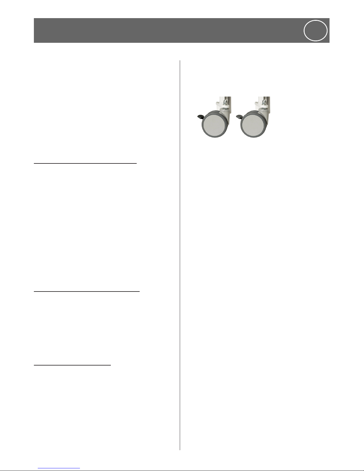
9.10 Castors and brakes
The FloorLine-i Plus and FloorLine-i bed is fitted
with Dual Wheel Castors as standard.
The set of standard wheel castors comprises:
• 1 black Steering/Directional Castor
• 3 grey Braked Castors
Directional lock
The Directional Lock (black) is located on one
castor at the head end. It can be locked in any
position to aid and ensure a smooth and straight
path down a hallway.
The Directional Lock Castor should be engaged
to the “ON” position at all times. To disengage
the Directional Lock, depress the “OFF” lever.
Braked castors
Braked Castors (grey) are locked by depressing
the front of the pedal on each castor lever.
This is done by foot pressure when wearing
appropriate protective shoes.
Brakes are released by depressing the top of the
castor lever until it unlocks.
o
Do not attempt to set or release
the brakes using your hands or
fingers as injury may occur.
The brakes shall not be used as running
brakes to decrease the speed of the bed
when it is moving.

www.humancaregroup.com
28
9. Operation Instructions
ENG
9.12 Moving the bed
o
Before moving the bed, raise
the mattress platform to a
minimum of 200mm from the
floor.
• When moving the bed, first release the
brakes on all castors so that the bed can
move freely.
• If brakes are not released and the bed is
forcibly moved when the wheels are locked,
the bed may be damaged.
• Re-engage the directional lock to assist with
steering.
• To control movement forwards or backwards
only, orientate the directional/steering
wheel, so it is parallel with the side edge of
the bed and then depress the lock lever to
the “ON” position with your foot. This will
engage a lock on this wheel which will permit
the bed to run straight forward or backward
when being moved. The wheel itself can be
positioned towards the front or the back of
the castor outrigger but it is recommended
to point down the bed’s length.
o
For safety, if leaving the bed
for any time ensure castors are
turned inwards and locked.
9.13 Folding the bed
For folding and storing, the bed needs to be
disassembled, please see assembly/disassembly
chapter.
9.14 CPR Emergency quick release system
(this information is only for the FloorLine-i
Plus bed)
The CPR emergency procedure (combined
rescue breathing and chest compressions) is
used on a patient in cardiac arrest. CPR can be
administered when the bed is in a CPR position a totally horizontally, flat mattress platform.
The FloorLine-i Plus bed is fitted with CPR Quick
Release Levers, and also a CPR button on the
Attendant Control Keypad.
CPR Quick Release Levers
Pull either one of the RED CPR Quick Release
Levers, located under either side of the backrest.
This will immediately (mechanically/manually)
lower the Backrest panel to a flat position.
When using the Emergency Release
Levers, DO NOT stop the backrest panel
until it has fully lowered, or actuator
damage may occur.
CPR button on the ACK
The bed will quickly and electrically level the
bed into the horizontally flat CPR position.
The sequence of movements firstly levels the
mattress platform to a horizontal/flat position,
then secondly flattens out the Backrest &
Kneebreak simultaneously. (Note: Early models
may have a different sequence!)
Regularly check the mechanics (see below)
of the CPR Quick Release Levers to ensure
the system is always operating correctly.
If intubation or head access is required…
1. Raise the bed, if it is at Floor-Level.
2. Remove the Headboard. There is no need
to place the headboard under the mattress,
as all Human Care bed platforms are solid
enough for effective chest compressions.
3. Release the Brakes, to allow the bed to be
pulled out from the wall for easy access to the
patient’s head. Once the bed is positioned,
reapply the brakes.
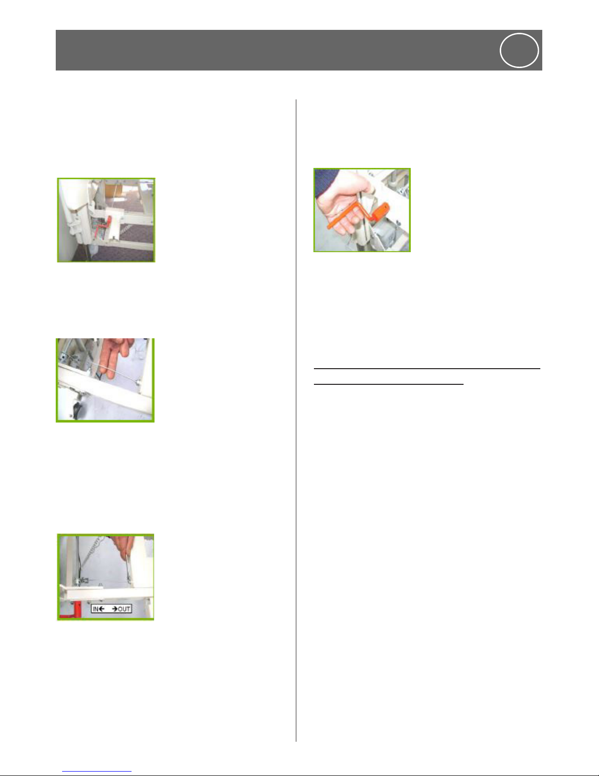
CPR Emergency Quick Release System, Testing
Operation & Making Adjustments
1. Raise the back rest using the handset, while
applying slight hand force to the top of the
29
www.humancaregroup.com
back rest panel. The back rest should raise to
it’s highest position; if it doesn’t then the CPR
cable is too tight and the release mechanism
is partially engaged. The cable needs to be
loosened via an adjustment (Photo 1).
Photo 1.
2. Check the CPR cable tension, it should not
be too tight, you should be able to move the
cable laterally slightly (Photo 2).
Photo 2.
3. The CPR cable is adjusted by loosening the
two locking nuts and moving the threaded
section in the required direction, ‘In’ to loosen
or ‘Out’ to tighten (Photo 3). Access to both
locking nuts can be gained from underneath
the mattress platform.
Photo 3.
4. Repeat Step 1, the back rest should raise to
it’s highest position with a slight downward
hand force applied.
5. To ensure that the quick release system is
operating properly, raise the back rest to it’s
highest position with the handset then by
using slight downward hand force on the top
of the back rest panel with one hand lift the
red CPR lever upward with the other using the
inside of your fingers (Photo 4). The back rest
panel should lower quickly.
photo 4.
Note: After an initial “Run-in” period, the
cable might loosen slightly. This is normal.
A minor adjustment should be made, as
per Step 3.
9.15 CPR & Intubation (this information is
only for the FloorLine-i bed)
The CPR emergency procedure (combined
rescue breathing and chest compressions) is
used on a patient in cardiac arrest.
CPR can be administered when the bed is in a
CPR position - a totally horizontally, flat mattress
platform.
If CPR, intubation or head access is required
1. Raise/lower the bed, to the preferred height.
Note: This FloorLine-i bed does NOT feature
any CPR Emergency Quick Release systems!
2. Remove the Headboard. There is no need
to place the headboard under the mattress,
as all Human Care bed platforms are solid
enough for effective chest compressions.
3. Release the Brakes, to allow the bed to be
pulled out from the wall for easy access to the
patient’s head. Once the bed is positioned,
reapply the brakes.
9. Operation Instructions
ENG

www.humancaregroup.com
30
10. Maintenance and service
ENG
10.1 Inspection, care and maintenance check list
User inspections should be carried out every 6 months, for the life of the bed. Care should be taken
when performing maintenance.
Serial No: ……...
Check:
See bed description, accessories and all functions
Check for Damage/Cleanliness
Confirm Secure
Perform Adjustment/Cleaning
OK Faults:
Action
Cleaning
Parts to Order
VISUAL CHECK of the Electrical Components
Cables - Plugs (Clips) No Cracks/Breaks, Correct Routing & No
Hanging Cables
Actuators & Junction Boxes
Control Box Unit
Battery Back-Up Unit
Under Bed Light
No Cracks/Breaks/Dents/Corrosion
Bulbs work
Securely Fitted
Handset
Attendant Control Keypad
Wireless Infrared Handset
Flexible User Panel
Casing/Membrane Faceplate Intact
Confirm backlit/indictor lights work
Confirm ACK handset ‘lockout’ works
Securely Fitted
Accessories (eg USB Ports, Service Monitor Intact, Clean, & Secure
VISUAL CHECK of the Mechanical Components
Nuts/Bolts, Screws/Pins, Lanyards/Clips, Hinges/
Mounts/Bushes-component fixing points
Wear/Damage, Tighten & Secure
Clean & Free
Chassis (Bed Base) - Bed Extension
End Covers
Push Handle
No Cracks/Dents
No Paintwork Flaked/Corroded
Clean & Securely Fitted
 Loading...