

Page 1

HUM Gesellschaft für Homecare
und Medizintechnik mbH
Zum Pier 79
44536 Lünen
Germany
Tel.: +49 (0) 231 / 88 08 85 - 0
Fax: +49 (0) 231 / 88 08 85 - 58
E-Mail: [email protected]
Internet: www.hum-online.de
ID 3701405 Rev. 1.0 | 21.01.2019
Page 2

sat 805 Pulse Oximeter
1 General ............................................................................................................................................... 7
1.1 Information on Operating Instructions .................................................................................................... 7
1.2 Symbol Designation ................................................................................................................................. 7
1.3 Liability and Warranty .............................................................................................................................. 8
1.4 Copyright Protection ................................................................................................................................ 9
1.5 Removal and Disposal .............................................................................................................................. 9
2 Safety ............................................................................................................................................... 11
2.1 Intended Use .......................................................................................................................................... 11
2.1.1 Possible Misapplications ................................................................................................................. 12
2.2 User Responsibility ................................................................................................................................. 13
2.3 Possible Dangers from the Equipment .................................................................................................. 14
2.4 Users ...................................................................................................................................................... 15
2.5 Customer Service ................................................................................................................................... 15
3 Technical Data ................................................................................................................................... 16
3.1 Unit Data ................................................................................................................................................ 16
3.2 Masimo Pulse Oximetry ......................................................................................................................... 17
3.3 Factory Default Settings ......................................................................................................................... 19
3.4 Life Times ............................................................................................................................................... 19
4 Assembly .......................................................................................................................................... 20
4.1 Displays and Controls ............................................................................................................................. 20
4.2 Connections ........................................................................................................................................... 20
4.3 LC Display ............................................................................................................................................... 21
4.4 Pictograms on the Device ...................................................................................................................... 22
4.5 Interfaces ............................................................................................................................................... 24
4.5.1 Analogue Interface .......................................................................................................................... 24
4.5.2 Nurse Call Alarm .............................................................................................................................. 25
2
Page 3

sat 805 Pulse Oximeter
4.5.3 USB2.0 Interface .............................................................................................................................. 25
4.6 Identification Nameplate ....................................................................................................................... 26
5 Shipping, Packaging and Storage ........................................................................................................ 27
5.1 Shipping Inspection ................................................................................................................................ 27
5.2 Scope of Delivery ................................................................................................................................... 27
5.3 Packaging ............................................................................................................................................... 28
5.4 Storage ................................................................................................................................................... 28
6 Operation ......................................................................................................................................... 29
6.1 Environmental Conditions ..................................................................................................................... 29
6.2 Prior to Initial Use .................................................................................................................................. 29
6.3 Mains operation / Charging the Batteries ............................................................................................. 29
6.3.1 Mains Power Failure Alarm ............................................................................................................. 31
6.4 Connections ........................................................................................................................................... 32
6.4.1 Connecting the Patient Cable and Sensor ....................................................................................... 32
6.4.2 Disconnecting the Sensor ................................................................................................................ 33
6.4.3 Disconnecting the Patient Cable from the Unit .............................................................................. 34
6.5 Installing the Unit ................................................................................................................................... 34
6.6 Using Masimo-Sensors ........................................................................................................................... 35
6.6.1 Selecting the (correct) Sensor ......................................................................................................... 36
6.6.1.1 Adhesive Sensors ...................................................................................................................... 36
6.6.1.2 Reusable Sensors ...................................................................................................................... 37
6.6.1.3 Patient Cable ............................................................................................................................. 38
6.6.2 Expected lifetimes of patient cables and sensors ........................................................................... 38
6.6.2.1 90%-Lifetime or „Near expiration“-message ............................................................................ 39
6.6.2.2 Life time exceeded .................................................................................................................... 40
6.7 Using the Interfaces ............................................................................................................................... 42
7 Control .............................................................................................................................................. 43
3
Page 4

sat 805 Pulse Oximeter
7.1 General ................................................................................................................................................... 43
7.2 Menu Operation..................................................................................................................................... 43
7.2.1 Using the Trim Knob ........................................................................................................................ 43
7.2.2 Calling the Main Menu .................................................................................................................... 44
7.2.3 Menu Structure ............................................................................................................................... 44
7.3 Switching on the Unit ............................................................................................................................. 45
7.4 Turning the Unit off ............................................................................................................................... 47
7.5 Alarm Limits (Alarm limits) ........................................................................................................... 48
7.5.1 Setting the Alarm Limits .................................................................................................................. 49
7.5.2 Setting the Alarm Filter ................................................................................................................... 50
7.6 Plethysmogram Display (Pleth-display) ....................................................................................... 52
7.7 Configuration (Configuration) ....................................................................................................... 53
7.7.1 Screen options (Screen) ............................................................................................................... 53
7.7.1.1 Contrast (Contrast) .............................................................................................................. 53
7.7.1.2 Backlight (Backlight) ........................................................................................................... 54
7.7.1.3 Menu Language (Language) .................................................................................................. 54
7.7.1.4 Access Permissions (Home Mode) .......................................................................................... 55
7.7.2 Acoustical Alarms (Acoust. Alarms) ....................................................................................... 57
7.7.2.1 Pulse Tone Volume (Volume Pulse) ................................................................................... 57
7.7.2.2 Alarm Tone Volume (Volume Alarm) .................................................................................. 58
7.7.2.3 Alarm Silence Time (Silence Time) ................................................................................... 59
7.7.3 Masimo Signal Processing (Signalprocessing)...................................................................... 60
7.7.3.1 Averaging Time (Averaging time) .................................................................................... 60
7.7.3.1 Perfusion Sensitivity (Algorithm mode)............................................................................. 61
7.7.3.3 SmartTone (SmartTone)........................................................................................................ 63
7.7.3.4 Artifact Filter (Artifact-Filter) ...................................................................................... 63
7.7.4 System Time (Clock) ..................................................................................................................... 64
4
Page 5

sat 805 Pulse Oximeter
7.7.5 External Alarm (Nurse Call) ...................................................................................................... 65
7.7.6 Device Information (Product Info)......................................................................................... 65
7.7.7 Analogue Interface (Analogue out) .......................................................................................... 66
7.8 Alarm lists (Alarm lists) ............................................................................................................... 67
7.8.1 Vital Alarm List (Vital alarm list) ....................................................................................... 68
7.8.2 Total Alarm List (Total alarm list) ..................................................................................... 68
7.8.3 Alarm Details ................................................................................................................................... 69
7.9 Trend Display (Trend) .......................................................................................................................... 70
7.9.1 Trend Display ................................................................................................................................... 70
7.10 Exporting the Data ............................................................................................................................... 71
8 Alarms .............................................................................................................................................. 73
8.1 General ................................................................................................................................................... 73
8.2 Alarm Categories .................................................................................................................................... 74
8.2.1 High Priority Alarms ........................................................................................................................ 74
8.2.1.1 SpO
8.2.1.2 Pulse Rate Alarm ....................................................................................................................... 75
8.2.1.3 Sensor Alarms ........................................................................................................................... 76
8.2.1.4 System Alarms .......................................................................................................................... 77
8.2.2 Medium Priority Alarms .................................................................................................................. 79
8.2.3 Low Priority Alarms ......................................................................................................................... 80
8.3 Status message ...................................................................................................................................... 81
8.4 Battery Alarms ....................................................................................................................................... 82
8.4.1 Battery Alarm (low priority) ............................................................................................................ 83
8.4.2 Battery Alarm (medium priority) ..................................................................................................... 83
8.4.3 Battery Alarm (high priority) ........................................................................................................... 83
Alarm ............................................................................................................................... 75
2
8.5 Combination of Alarms of Different Priorities ....................................................................................... 83
9 Malfunctions and Troubleshooting .................................................................................................... 84
5
Page 6

sat 805 Pulse Oximeter
10 Disinfecting, Cleaning and Maintenance ........................................................................................... 89
10.1 Cleaning Plan ........................................................................................................................................ 89
10.2 Disinfection .......................................................................................................................................... 90
10.2.1 Disinfecting the Unit ...................................................................................................................... 90
10.2.2 Disinfecting the Masimo sensors .................................................................................................. 90
10.2.3 Disinfecting the patient cable ....................................................................................................... 91
10.3 Cleaning................................................................................................................................................ 92
10.3.1 Cleaning the Unit ........................................................................................................................... 92
10.3.2 Cleaning of Masimo-Sensors ......................................................................................................... 92
10.3.3 Cleaning of Patient Cables ............................................................................................................. 93
10.4 Maintenance ........................................................................................................................................ 93
10.4.1 Regular Check ................................................................................................................................ 94
10.4.2 User Check of Alarm Function ....................................................................................................... 94
11 Accessories and Replacement Parts ................................................................................................. 96
11.1 Accessories ........................................................................................................................................... 96
12 Advanced Information ..................................................................................................................... 97
12.1 Averaging Time .................................................................................................................................... 97
12.2 Alarm Signal Generation Delay ............................................................................................................ 98
13 Index ............................................................................................................................................... 99
6
Page 7

sat 805 Pulse Oximeter
General
1 General
1.1 Information on Operating Instructions
These operating instructions describe the safe and appropriate handling of the unit. Adherence to specific
safety notices and instructions as well as to the applicable on-site accident prevention regulations and
general safety regulations is an imperative requirement.
Before beginning all work on the unit, read the operating instructions completely; in particular the chapter
regarding safety and the respective safety notices. The reading must have been understood.
The manual is a component of the unit. It is to be kept accessible at all times in direct proximity of the unit.
The operating instructions must always be passed on with the unit to third parties.
1.2 Symbol Designation
Important technical safety notices in these operating instructions are designated by symbols.
These specified notices on industrial safety must be strictly complied with and adhered to. Behave
cautiously in these cases especially in order to avoid accidents, damages to unit and people.
WARNING! Injury or Mortal Danger!
This symbol marks notices that, if not observed, can lead to health impairments, injuries, lasting
bodily injury or to death.
CAUTION! Electric Shock Hazard!
This symbol draws attention to dangerous situations from electric current. The danger of severe
injury or death exists from not observing the safety notices. Required work may be performed
only by a qualified electrician.
ATTENTION! Risk of Unit Damage!
This symbol designates notices that, if not observed, can lead to damages, malfunctions, and/or
loss of the equipment.
NOTICE!
This symbol designates tips and information that are to be considered for efficient and trouble-free
handling of the unit.
7
Page 8

sat 805 Pulse Oximeter
General
INFORMATION!
This symbol marks notices to clarify specific specialized terms.
1.3 Liability and Warranty
All data and notices in this operating manual were arranged in consideration of valid regulations, the
current state of the art, as well as our many years of knowledge and experience.
This operating manual must be read carefully before beginning all work on and with the unit! The
manufacturer does not accept liability for damages and malfunctions that result from not observing the
operating instructions.
The German version of these operating instructions is applicable. Translations of the operating instructions
also have been provided to the best of our knowledge. However, we cannot accept liability for translation
errors.
The text and graphic representations do not correspond necessarily to the supply scope. The designs and
diagrams do not correspond to the scale 1:1.
The current supply scope can vary from the presently described data and notices, as well as the graphic
representations due to the use of additional order options with special unit or based on the newest
technical changes. If you have question, please contact the manufacturer.
We reserve the right to make technical changes on the product within the context of improving and
advancing performance characteristics.
We warrant our sat 805 to be free from manufacturing defects in materials and workmanship for two years
starting from the date of delivery.
Product warranties remain valid provided the product was properly installed and used.
Defects, malfunctions, or failures of the warranted product caused by damage resulting from Acts of God
(such as floods, fire, etc.), environmental and atmospheric disturbances other external forces such as
power line disturbances, host computer malfunction, misconnections, and damage caused by misuse,
abuse, and unauthorized alteration or repair, are not warranted.
A product will not be warranted in the following situations:
• The product has been found to be defective after the warranty period has expired.
• The product has been subjected to misuse, abuse, or unauthorized repair, whether by accident or other
cause. Such conditions will be determined by HUM Gesellschaft für Homecare und Medizintechnik mbH at
its sole and unfettered discretion.
• The product is damaged beyond repair due to natural disasters, such as by lightning, flood, earthquake,
etc.
8
Page 9

sat 805 Pulse Oximeter
General
– Keep the packaging in order to ship the unit intact in case service is required.
Nonetheless, if the packing material should nevertheless be disposed of, the disposal
regulations valid in the respective country are to be followed.
• The product in question is either software, or an expendable item, such as a fuse, battery, etc.
This warranty is limited to the repair and/or replacement, at HUM Gesellschaft für Homecare und
Medizintechnik mbH sole discretion, of the defective product during its warranty period. HUM Gesellschaft
für Homecare und Medizintechnik mbH will replace any product found to be defective within the first three
months of purchase provided said product was properly installed and used.
For Masimo cables and sensors, the warranty terms of manufacturer Masimo Corp. apply.
1.4 Copyright Protection
The instruction manual is to be kept confidential. It is exclusively intended for active personnel that work
on and with the unit.
All textual data, texts, drawings, illustrations, and other representations are predicted by copyright laws
and are entitled additionally to commercial patent rights. Each abusive use is subject to prosecution.
Transfer to third parties, duplication in any shape or form (also in part), as well as the utilization and/or
reporting of the contents are not permitted without written permission from the manufacturer. Offences
are subject to compensation. Additional rights remain reserved.
We reserve the right to exercise all rights relating to conditional patent rights.
This device is covered by one or more of the following U.S. Patents:
RE38,492, RE38,476, 7,221,971, 7,215,986, 7,215,984, 6,850,787, 6,826,419, 6,822,564, 6,816,741,
6,745,060, 6,699,194, 6,684,090, 6,654,624, 6,650,917, 6,643,53, 6,606,511, 6,501,975, 6,463,311,
6,430,525, 6,360,114, 6,263,222, 6,236,872, 6,229,856, 6,157,850, 6,067,462, 6,011,986, 6,002,952,
5,919,134, 5,769,785, 5,758,644, 5,685,299, 5,632,272, 5,490,505, 5,482,036 and their international
equivalent patents. Other US and international patents are pending.
Possession or purchase of this device does not convey any express or implied license to use the device with
unauthorized sensors or cables, which would, alone, or in combination with this device, fall into the scope
of one or more of the patents relating to this device.
1.5 Removal and Disposal
9
Page 10

sat 805 Pulse Oximeter
– The disposal of infectious supplies (e.g. Masimo sensor with an infection from the
user) has to be accomplished by a certified disposal company. You can request its
address from city council.
– The unit contains batteries, which are not allowed to be discarded into the domestic
refuse. Therefore, rather than throw the batteries into the domestic refuse, dispose
of them instead at an appropriate collection site.
– If the unit's end of usage stage has been reached, it is to be disposed of according to
the laws. Alternatively, the unit can be returned to the dealer, who then takes over
the professional disposal.
10
Page 11

sat 805 Pulse Oximeter
Safety
2 Safety
This section gives an overview of all important safety aspects for optimal prediction of humans as well as
for the safe and trouble-free operation of the unit.
Additionally, the individual chapters contain precise safety notices (designated by symbols) for the
prevention of imminent danger. Furthermore, existing pictograms, signs, and inscriptions on the unit must
be observed and are to be maintained in well readable condition.
2.1 Intended Use
The unit is intended to be used for the continuous monitoring of functional oxygen saturation and pulse
frequency. It has an alarming function in case of deviations from the adjusted alarm limits.
The unit is suitable for monitoring newborns, pediatric and adult patients. Only the certified Masimo
sensor may be used for the respective patient type.
Due to its structure and its configuration, the unit can be used domestically, in the clinical setting and in the
sleep laboratory stationary and mobile, inside and outside of these areas.
The pulse oximeter is considered to be an early warning system. If a possible undersupply of a patient's
oxygen is indicated, a more exact investigation is immediately necessary.
ATTENTION!
Each use of the unit beyond that recommended by law and or misuse is forbidden and is considered to be
in violation of the law.
Claims of any kind against the manufacturer and/or its authorized personnel on account of damage from
improper use of the unit are forbidden.
The user of the unit is solely responsible for all damages resulting from improper use.
Proper adherence to these operating conditions, as well as the data and the instructions are considered to
be proper use.
The unit may not be opened or modified.
Parts other than those pertaining to the supply scope may be used only after release by the company, HUM
Gesellschaft für Homecare und Medizintechnik mbH.
11
Page 12

sat 805 Pulse Oximeter
Safety
2.1.1 Possible Misapplications
WARNING! Fire Hazard!
The pulse oximeter may not be used during nuclear magnetic resonance imaging tests. The
electrical current induced there can cause burns. This may affect the MRI image and the MRI
device may affect the accuracy of the Pulse Oximetry parameters and measurements.
– This device is to be operated by qualified personnel only. This manual, all precautionary information
and specifications should be read before use.
– The pulse oximeter may not be used to monitor breathing (apnea monitor.). This may take place
only with special respiratory monitoring equipment.
– A pulse oximeter should be considered an early warning device. As a trend towards patient
hypoxemia is indicated, blood samples should be analyzed by a laboratory co-oximeter to completely
understand the patient’s condition.
– Pulse rate measurement is based on the optical detection of a peripheral flow pulse and therefore
may not detect certain arrhythmias. The pulse oximeter should not be used as a replacement or
substitute for ECG based arrhythmia analysis.
– Explosion hazard. The pulse oximeter may not be used in a combustible atmosphere. This can
develop when working with flammable anesthetics, laughing gas, or other combustible gases and
liquids.
– If an alarm condition (other than the exceptions listed herein) occurs while the alarm tone volume is
set to off, the only alarm indications will be visual displays and symbols related to the alarm
condition.
– Do not use any extensions power cords or adapters of any type. The plug-in power supply must be
intact and undamaged.
– The pulse oximeter may not be operated in a switchable power socket. Such a plug socket is
unsuitable for a secured power supply.
– The pulse oximeter works with an optical measurement procedure and should not be operated near
to strong and/or direct light sources.
– Only use one sensor per measuring point to avoid interferences.
– Pay attention to a secured and fixed location of the sensors!
12
Page 13

sat 805 Pulse Oximeter
Safety
– The presence of carboxyl (HbCO)-, methaemoglobin, (Hbmet) or diluted dyes or substances
containing dyes in the blood stream can influence the measurements and can lead incorrectly to
higher values.
– When using the pulse oximeter near equipment, which emits strong electromagnetic signals, (e.g.
mobile telephones, monitors, etc.) the functionality can be reduced.
– SpO2 is empirically calibrated to functional arterial oxygen saturation in healthy adult volunteers with
normal levels of carboxyhemoglobin (COHb) and methemoglobin (MetHb). A pulse oximeter cannot
measure elevated levels of COHb or MetHb. Increases in either COHb or MetHb will affect the
accuracy of the SpO
– Elevated levels of Methemoglobin (MetHb) will lead to inaccurate SpO2 measurements.
When elevated levels of MetHb are suspected, laboratory analysis (co-oximetry) of a blood sample
should be performed.
– Elevated levels of Carboxyhemoglobin (COHb) will lead to inaccurate SpO2 -measurements. When
elevated levels of COHb are suspected, laboratory analysis (co-oximetry) of a blood sample should be
performed.
measurement.
2
– Elevated levels of Total Bilirubin may lead to inaccurate SpO2 measurements.
– Severe anemia may cause erroneous SpO2 readings.
2.2 User Responsibility
This user manual information must be kept within direct proximity of the unit and must be available to
those using the equipment at any time.
The unit may only be used in technically sound and operational condition. Before each use the unit must
be examined for any possible defects.
The directions in the user manual are to be followed completely and without any changes!
In order to use the unit, the directions in this user manual, the stated safety indicators, the local accident
prevention regulations and general safety guidelines, as well as current environmental provisions are to be
observed and implemented.
The user and his authorized personnel are responsible for the functioning of the unit without interference
as well a defined designation of responsibility for installation, usage, maintenance and cleaning of the unit.
The equipment requires responsible and prudent usage. Unauthorized use or usage by unauthorized
personnel can endanger lives.
13
Page 14

sat 805 Pulse Oximeter
Safety
2.3 Possible Dangers from the Equipment
The unit has undergone endangerment analysis. The construction and execution of the unit is expanded
upon and is equivalent to the current state of technology.
And yet risks remain!
WARNING! Health Risk!
Particular supervision is necessary if the unit is used near children or bedridden individuals.
Use with small children may never occur without additional monitoring!
CAUTION! Danger from Electrical Current!
Electrical power can cause severe injuries. Damaging the insulation or individual parts is life
threatening.
Therefore:
– Work on the unit may only take place by trained specialists.
– Before any work on the unit remove it from the network connection!
– Before each use always check network connection cables for damage.
CAUTION! Danger from Rechargeable Batteries!
The unit contains rechargeable Lithium Ion batteries.
– Do not throw batteries into a fire or expose them to high temperatures. Risk of explosion
exists.
– With incorrect usage, liquid could escape from the cells. This can lead to skin irritations. Avoid
contact with this liquid. If contact occurs, rinse area with plenty of water. If the liquid gets
into the eyes, rinse at once for 10 minutes with water and visit a doctor immediately.
– If it becomes necessary to replace the batteries, please contact your medical device supplier
our customer service. We assume no liability for improperly replaced batteries.
14
Page 15

sat 805 Pulse Oximeter
Safety
Office Hours:
Monday - Thursday 8.00 a.m. - 4.30 p.m. | Friday 8.00 a.m. - 3.45 p.m.
Address:
HUM Gesellschaft für Homecare und Medizintechnik mbH
Zum Pier 79 | 44536 Lünen | Germany
Phone:
+49 (0) 231 / 88 08 85 - 0
Fax:
+49 (0) 231 / 88 08 85 - 58
Internet:
www.hum-online.de
E-Mail:
ATTENTION! Observe High Frequency Noise Stability!
Medical instruments can be influenced by (mobile) RF-communication installations (e.g. cell
phones).
Do not use cell phones in the direct vicinity of the unit.
ATTENTION! Observe Electromagnetic Compatibility!
Medical electrical equipment is subject to special safety regulations regarding electromagnetic
compatibility (EMC) and must be used and installed according to directions in the EMC document.
Pay special attention to:
– Floors should be made of wood or concrete, or covered with ceramic tiles. If the floor consists of
synthetic materials, the relative humidity must be at least 30%.
– The unit may not be exposed to strong magnetic fields during operation.
– Magnetic fields in the network frequency must correspond to typical values found in business or
hospital environments.
2.4 Users
The unit may only be used by trained specialists and instructed users. The configuration of the unit (e.g.
the alarm limits) in particular has to take place with corresponding medical expertise.
2.5 Customer Service
If assistance in commissioning, in operation or maintenance is needed, or you would like to report an
unexpected operation or incident with sat 805, you can contact HUM Gesellschaft für Homecare und
Medizintechnik mbH as follows:
15
Page 16

sat 805 Pulse Oximeter
Technical Data
Feature
Value
Unit dimensions (L x W x H)
92 x 240 x 104 mm
Weight,
including batteries
900 g
Power pack
100-240 V ~50/60 Hz
9.3 V DC +/-1 %
1,29 A 12 W
Internal power supply
- Lithium Ion batteries
7,2 V / mind. 3,6 Ah
Battery autonomy
20 hours guaranteed
24 hours typical
Environmental Conditions
Operation:
Temperature
Humidity
Air pressure
+5° to +40°C
15% to 93%, non-condensing
600 mbar to 1060 mbar
Environmental Conditions
Storage:
Temperature
Humidity
Air pressure
-25° to +70°C
15% to 93%, non-condensing
600 mbar to 1060 mbar
Classification in accordance with
MDD (Medical Device Directive)
ll b
3 Technical Data
3.1 Unit Data
16
Page 17

sat 805 Pulse Oximeter
Technical Data
Characteristic Data
SpO
2
Pulse
Display range
1-100 %
25-240 1/min
Accuracy
– without Movement, Adults,
Children and Newborns
25-240 1/min+/- 3 digits
Accuracy
– with Movement, Adults, Children
and Newborns
25-240 1/min+/- 5 digits
Accuracy
– without Movement, Adults and
Children
70-100 %+/- 2 digits
0-69% not specified
Accuracy
– without Movement, Newborns
70-100 %+/- 3 digits
0-69% not specified
Accuracy
– under Movement, Adults, Children
and Newborns
70-100 %+/- 3 digits
0-69% not specified
Accuracy
1 %
1 1/min
Data update interval
1 Hz
1 Hz
3.2 Masimo Pulse Oximetry
The Masimo SET Technology with LNOP Adt sensors has been validated for no motion accuracy in human blood studies on healthy adult volunteers
in induced hypoxia studies in the range of 70-100% SpO2 against a laboratory cooximeter and ECG monitor. This variation equals plus or minus one
standard deviation which encompasses 68% of the population.
The Masimo SET Technology with LNOP Adt sensors has been validated for motion accuracy in human blood studies on healthy adult volunteers in
induced hypoxia studies while performing rubbing and tapping motions, at 2 to 4 Hz at an amplitude of 1 to 2 cm and a non-repetitive motion
between 1 to 5 Hz at an amplitude of 2 to 3 cm in induced hypoxia studies in the range of 70-100% SpO2 against a laboratory co-oximeter and ECG
monitor. This variation equals plus or minus one standard deviation which encompasses 68% of the population.
The Masimo SET Technology with LNOP Neo and Neo Pt sensors has been validated for neonatal motion accuracy in human blood studies on
neonates while moving the neonate's foot at 2 to 4 Hz at an amplitude of 1 to 2 cm against a laboratory co-oximeter and ECG monitor. This
variation equals plus or minus one standard deviation which encompasses 68% of the population.
17
Page 18
sat 805 Pulse Oximeter
Technical Data
Perfusion
Display range
0.02-20.0 %
Setting Range of the Alarm Limits
Upper Limit oxygen saturation
42-100 %
Lower Limit oxygen saturation
40-98 %
Upper Limit pulse frequency
27-240 1/min
Lower Limit pulse frequency
25-238 1/min
Alarm tone loudness
70 dbA
Sensor
Wavelengths
660 nm (red), 905 nm (infrared)
max. Light Wattage
0.79 mW
NOTICE!
A functional tester cannot be used to assess the accuracy of a pulse oximeter probe or a pulse
oximeter.
NOTICE!
If there is independent demonstration that a particular calibration curve is accurate for the
combination of a pulse oximeter and a pulse oximeter probe, then a functional tester can measure the
contribution of a monitor to the total error of a monitor/probe system. The functional tester can then
measure how accurately a particular pulse oximeter is reproducing that calibration curve.
NOTICE!
Information about wavelength range can be especially useful to clinicians.
18
Page 19
sat 805 Pulse Oximeter
Technical Data
Setting
Value
Alarm tone volume
5
Pulse tone volume
5
Alarm tone mute time
60 sec
Contrast
5
Averaging Time
8 sec
Perfusion sensitivity
normal
Nurse Call
N(ormally) O(pen)
Alarm limit SpO2 high
100 %
Alarm limit SpO2 low
85 %
Alarm limit Pulse high
160 1/min
Alarm limit Pulse low
40 1/min
Alarm filter SpO2 low
OFF
Alarm filter Pulse high
OFF
SmartTone
ON
Artifact Filter
OFF
Component
Value
sat 805
5 years
Batteries
3 years
Patient cable
17280 hours, X-CAL - limited
Pulse oximetry sensor, reusable
8760 hours, X-CAL - limited
Pulse oximetry sensor, not reusable
168 hours, X-CAL - limited
3.3 Factory Default Settings
3.4 Life Times
The Masimo X-CAL feature will prevent the use of components with an error message after the
abovementioned hours. A use after this expected life could lead by faulty measurements to a possible risk
for the patient. For further information on Masimo X-CAL, please refer to chapter 6.6.2.
19
Page 20
sat 805 Pulse Oximeter
Assembly
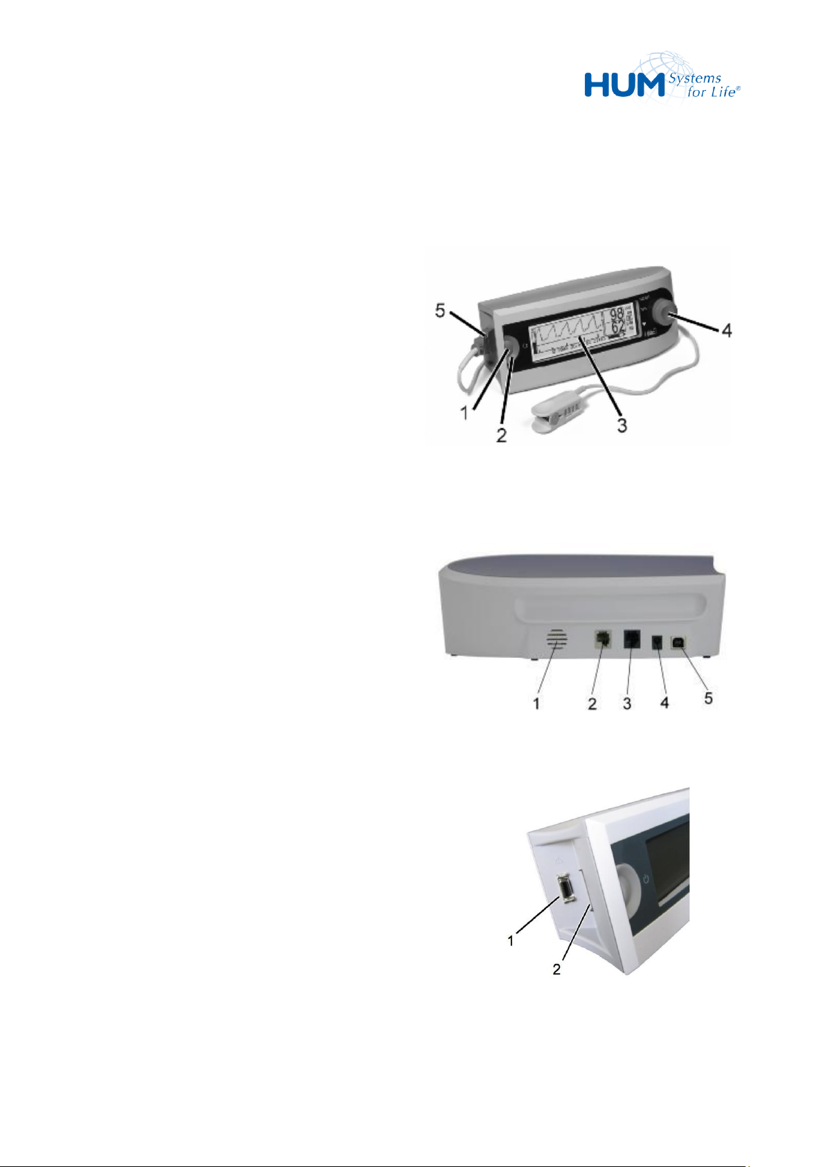
1 Green mains LEDs (behind the ON/OFF-
button)
2 ON-/OFF button
3 LC Display
4 Trim knob incl. yellow/red alarm LEDs
5 Connector for patient cable
Fig. 1: Display and Controls
Connections in the rear panel:
1 Alarm loud speaker
2 Interface connector, nurse call
3 Interface connector, analogue
4 AC adapter socket
5 USB 2.0
Fig. 2: Rear Panel
Connections in the left panel:
1 Patient lead connection
2 SD Card slot
Fig. 3: Left Panel
4 Assembly
4.1 Displays and Controls
4.2 Connections
20
Page 21
sat 805 Pulse Oximeter
Assembly
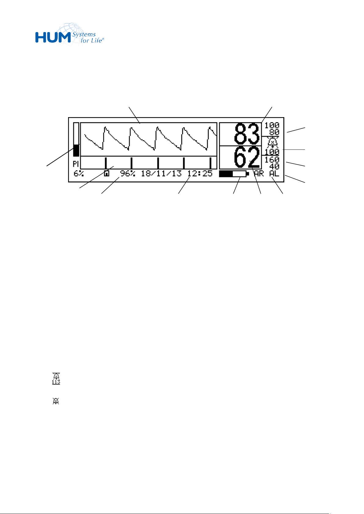
Fig. 4: LC Display
1 Perfusion index, graphical and numerical display in %
2 IQ bar, displays graphically the Signal IQ in normal operation. The Signal IQ is an indicator for
signal insufficiency.
3 Remaining memory in %
4 Status line: Alarm messages, time and date, memory status and other parameters are displayed.
5 Actual battery capacity.
6 Pulse frequency in beats per minute (1/min), alarm limits high and low.
7 AR – symbol, is displayed when the Artifact Filter is active.
8 AL – symbol, is displayed when the ALarm filter is active.
9 Alarm limits pulse frequency.
10 Alarm tone mute symbol and remaining time in seconds.
: if the audio alerts are temporarily suppressed.
: if the audio alerts are switched off.
11 Alarm limits oxygen concentration.
12 Current oxygen saturation in %
13 Plethysmogram, displays in normal operation the current pulse trace.
1
2
3 4 5 6 7
8
9
10
11
12
13
4.3 LC Display
21
Page 22
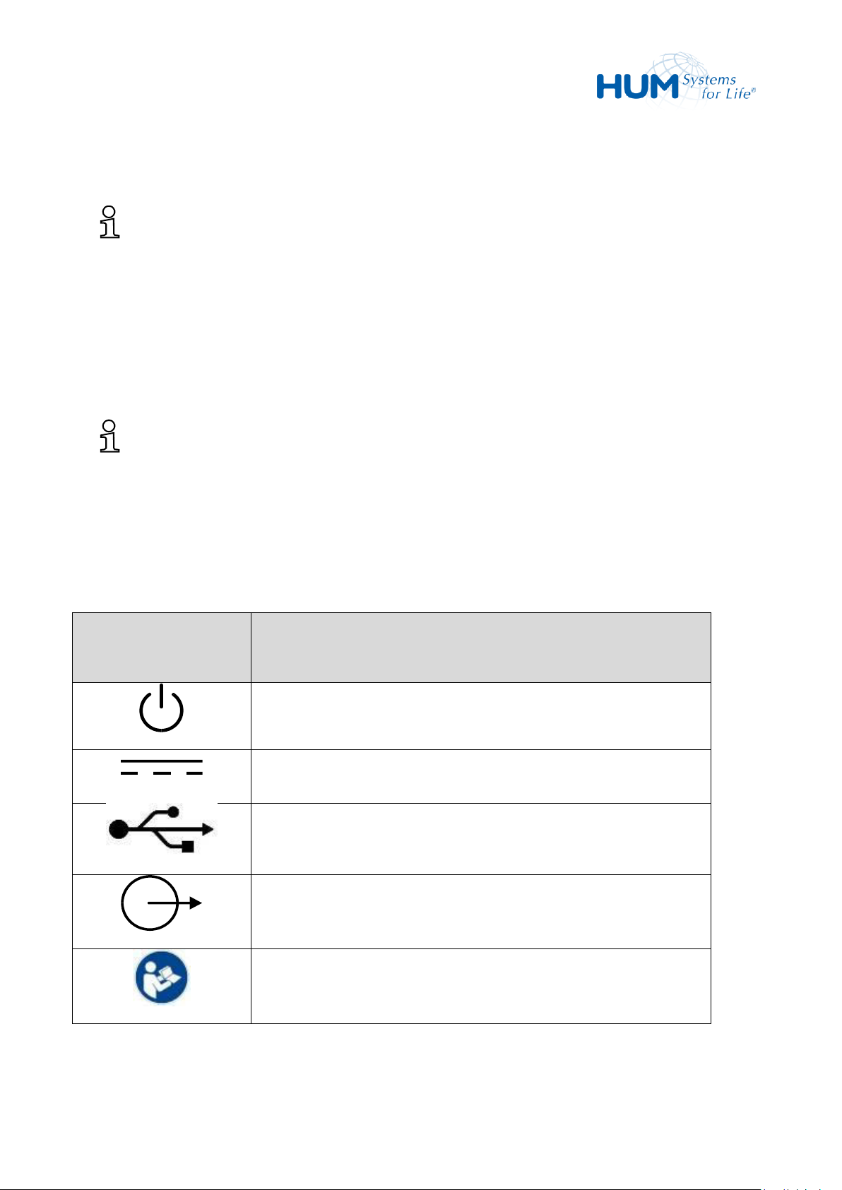
sat 805 Pulse Oximeter
Assembly
Symbol
Meaning
ON-/OFF-Button
DC current power connector
USB connector
Analogue interface
Nurse call interface
ATTENTION! Read instructions for use!
What is signal IQ™?
Signal-IQ™ is a measurement for Signal-Identification and Signal-Quality. Masimo developed this
indicator to give the user information when a measurement is questionable. Signal-IQ™ is a visual
reliability indicator for the oxygen saturation and pulse frequency measurements.
The more difficult it is to detect an arterial pulse signal the lower the presented IQ-bar (2). The
Signal-IQ-figure is particularly valuable with movement, weak circulation, or environmental
influences.
What is the Perfusion-Index?
The Perfusion-Index is a measurement for pulse strength at the point of sensor measurement. The
Perfusion-Index varies from 0.02% (very weak pulse strength) to 20% (very strong pulse signal). The
Perfusion-Index is calculated from the reflected infrared portion. The Perfusion-Index is a relative
measurement and can vary at each application point and with different patients.
4.4 Pictograms on the Device
22
Page 23
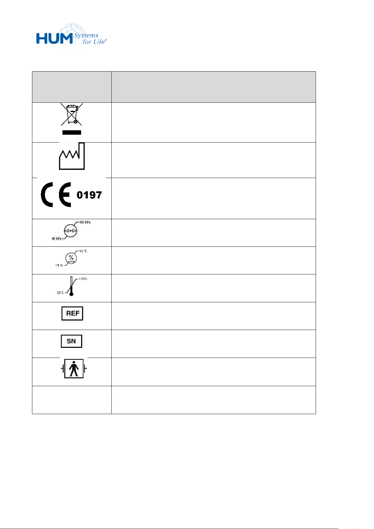
sat 805 Pulse Oximeter
Assembly
Symbol
Meaning
The device and its components are not allowed to be discarded into
normal household waste
Manufacturer and year of manufacture
Notified Body TÜV Rheinland LGA Products GmbH
Legitimate air pressure range for storage
Legitimate air humidity range for storage
Legitimate temperature range for storage
Model Number
Serial Number
Applied part type BF
IP 22
Protection against contact with fingers and medium sized solid foreign
objects, protection against slanty falling dripping water
23
Page 24
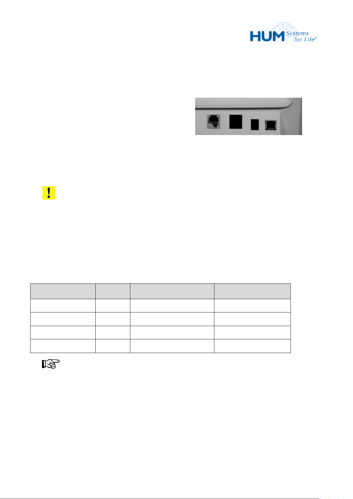
sat 805 Pulse Oximeter
Assembly
– Interface connectors in the rear panel of the
unit (from left to right):
– Nurse call
– Analogue interface (right)
– DC input
– USB
Fig. 5: Interface Connector
Parameter
Pin No.
Value Range
Voltage Range
Plethysmogram
2
0 – 255
0 – 2,5 volts
Ground
3
SpO2
4
0 – 100 %
0 – 1,0 volts
Pulse frequency
5
0 – 240 1/min
0 – 2,4 volts
4.5 Interfaces
The unit features following interfaces:
ATTENTION!
To connect to the interface use only original manufactured parts.
Otherwise the unit could be damaged.
4.5.1 Analogue Interface
The analogue interface signals are output as follows:
NOTICE!
The analogue voltages are constantly supplied to the interface and cannot be configured.
24
Page 25
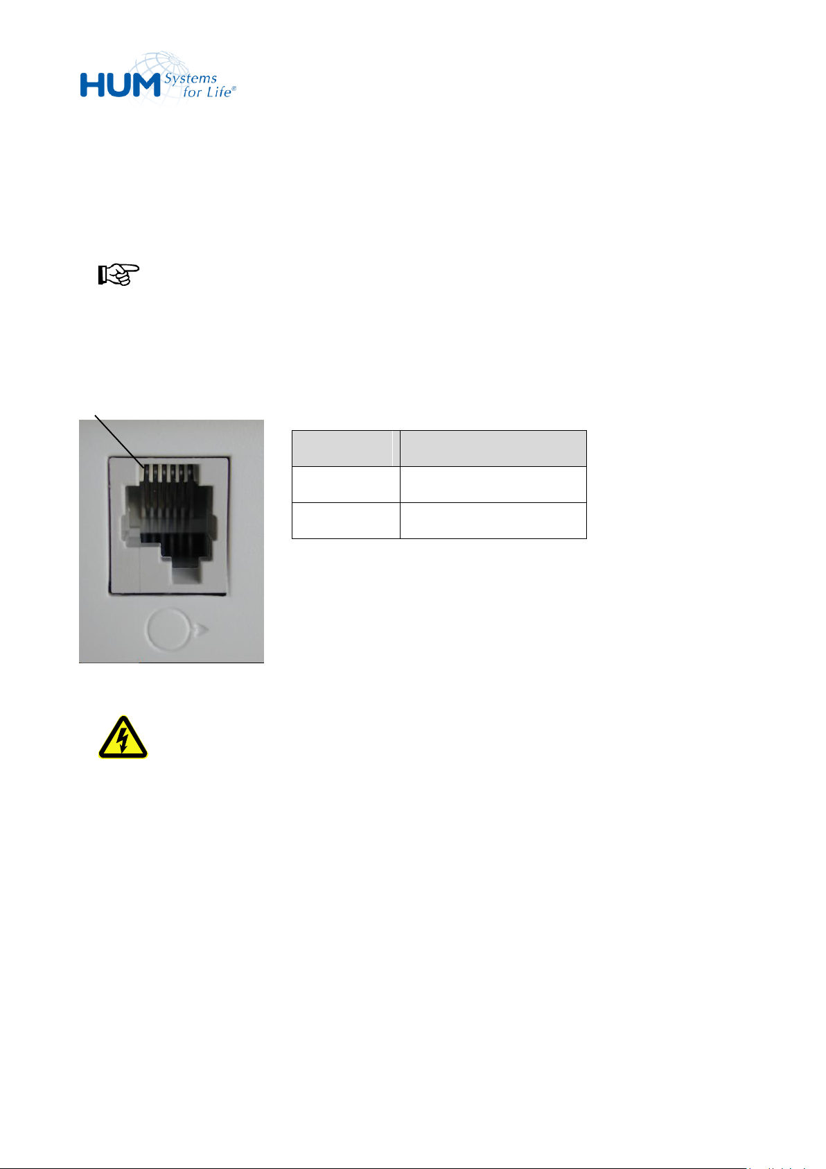
sat 805 Pulse Oximeter
Assembly
Pin1
Pin no.
Signal
3
Relay terminal 1
4
Relay terminal 2
4.5.2 Nurse Call Alarm
The nurse call alarm interface can be configured for connection to a nurse call system or a remote alarm
device.
NOTICE!
Even if the acoustic alarm has been silenced on the device, the acoustic alarms still always sound on
the external alarm interface.
Pin assignment for the external alarm interface is as follows:
Fig. 6: External Alarm interface
CAUTION! Danger by Failure of the Alarm System!
With a failure of the alarm system, there are NO alarm signals available!
4.5.3 USB2.0 Interface
The USB interface is for service and maintenance use only.
25
Page 26
sat 805 Pulse Oximeter
Assembly
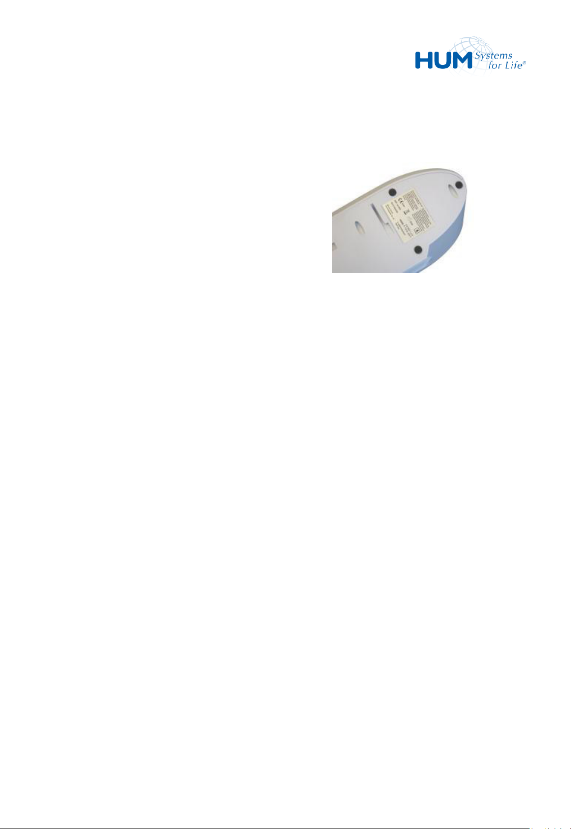
The following information can be found there:
– Manufacturer
– Unit description
– Production year
– Serial number
– Power supply
– Type number
Fig. 7: Identification Nameplate
4.6 Identification Nameplate
The nameplate is located on the bottom side of the unit.
26
Page 27
sat 805 Pulse Oximeter
Shipping, Packaging and Storage
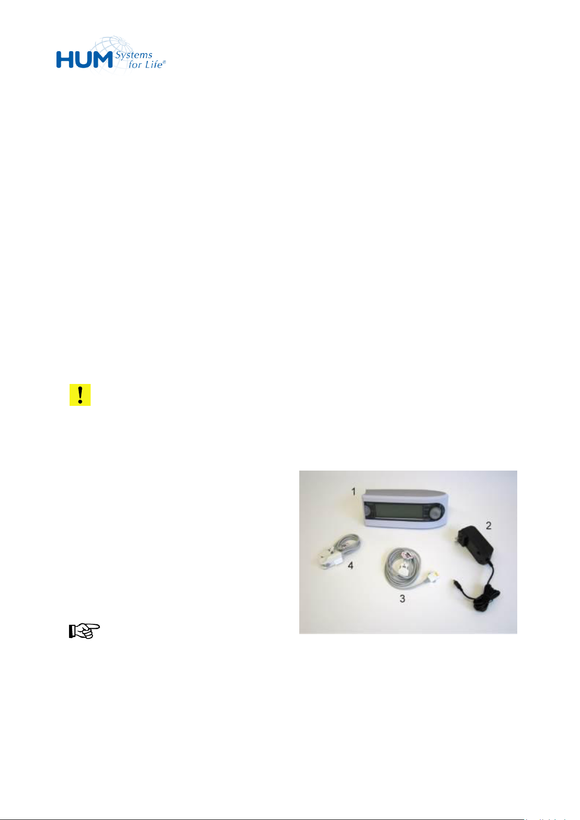
Scope of delivery:
1 Pulse oximeter sat 805
2 Plug-in power supply unit
3 Patient lead
4 One or several pulse oximetry sensors
NOTICE!
With regard to the sensors the actual scope of
delivery can be adjusted to the user requirements
and can differ from the pictured scope of delivery!
Fig. 8: Scope of Delivery
5 Shipping, Packaging and Storage
5.1 Shipping Inspection
Examine the delivery immediately upon receipt for completeness and possible shipping damage.
With visible external shipping damage do not accept delivery or only with reservation.
Indicate the extent of damage on the accompanying delivery document i.e. on the shipping agent’s
document. Start the claim procedure.
Report invisible damage immediately after discovery. Damage claims can only be processed during the valid
time period for claim acceptance.
5.2 Scope of Delivery
Please check the contents of the package immediately following receipt. If the items are missing, please
contact your medical equipment dealer immediately.
ATTENTION!
Never use other accessories than specified.
27
Page 28

sat 805 Pulse Oximeter
Shipping, Packaging and Storage
5.3 Packaging
To minimize damage always transport or send the unit in its original packaging. We recommend you to
save the packaging.
WARNING! Risk of Suffocation!
Packaging materials are not intended for children. The danger of suffocation exists.
ATTENTION! Dangerous for the Environment!
Always dispose of packaging materials in environmentally correct manner and according to local
disposal regulations. If need be call the recycling company.
5.4 Storage
Only store the unit under the following conditions:
– For shorter periods of storage, store the device with batteries half-charged.
– For longer periods of storage without usage, let the batteries getting removed. Therefore, please
contact your medical device supplier.
– Secure the unit before storage or turn OFF.
– Do not store outside.
– Store in dry dust free area.
– Do not expose to aggressive media.
– Prevent sunlight exposure.
– Avoid mechanical vibrations.
– Storage temperature -25 to +70 °C.
– Relative humidity maximum 93%.
– With longer storage time regularly check the general condition of all parts and the packaging.
Protect the unit from unauthorized access (theft, acquisition, and usage by unauthorized third party).
28
Page 29

sat 805 Pulse Oximeter
Operation
6 Operation
6.1 Environmental Conditions
The unit uses high frequency energy exclusively for its internal functions. That is why its high frequency
emission is very low and it is improbable that electronic units in close vicinity can be disturbed.
The unit is intended for use in all environments including homes and those directly connected to a public
service network, which also serves buildings with living spaces.
Floors should consist of wood or cement or be covered with ceramic tiles. If the flooring is covered with
synthetic materials the relative humidity has to be at least 30%.
6.2 Prior to Initial Use
Before using the unit for the first time, familiarize yourself with it and its accessories. This absolutely
includes reading the user manual.
WARNING! Danger to the Patient!
The unit is used to monitor patients. That is why it should only be used and configured by trained
and instructed users.
Prior to the assembly check if all system components needed for a proper operation are available.
Please contact the manufacturer or your medical device supplier for help in commissioning, in
operation, maintenance or any other way. You can find the address of the manufacturer in Ch. 2.5.
The address of the supplier was handed over while briefing. Furthermore contact the companies as
stated above in case of an unexpected operating status or incidents as well.
In application in domestic field a documented briefing is absolutely mandatory! Before using the
unit on a patient for the first time, it must be turned on and tested.
6.3 Mains operation / Charging the Batteries
The power supply for monitoring can be done without a power supply unit – it can also be provided by the
built-in battery. With a fully-charged battery, the power supply is guaranteed for at least 20 hours of
monitoring.
When the device is switched on, the current battery capacity is permanently displayed to the user as an
icon on the LCD display. If the battery capacity is no longer sufficient, in other words monitoring is
guaranteed for less than 1 hour, the battery alarm is activated.
Before first use, carry out a complete charge cycle.
29
Page 30
sat 805 Pulse Oximeter
Operation
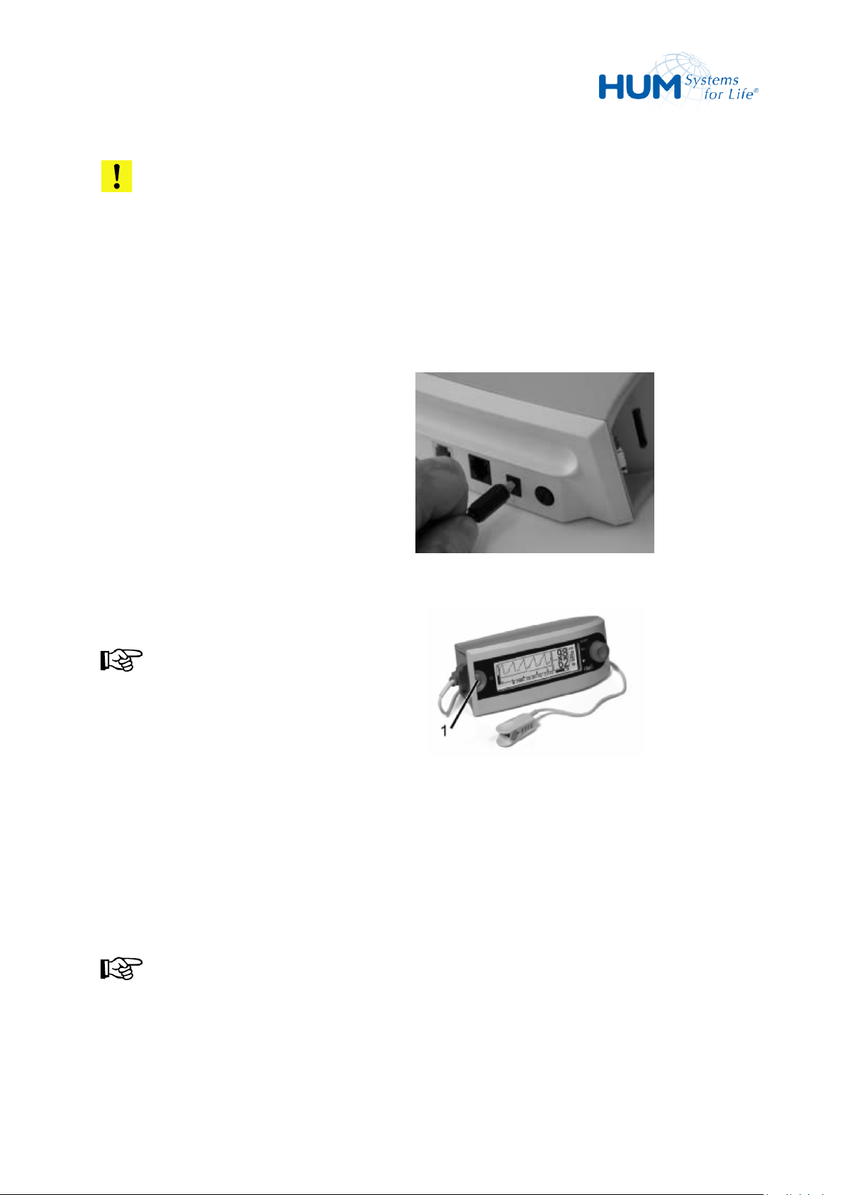
1. Connect the mains adapter plug to the
unit connector.
2. Plug the other end of the cable into an
electric outlet.
Fig. 9: Mains Power Adapter Plug
3. The green network-LEDs (1) display.
NOTICE!
The green network-LEDs only signal that
the unit is supplied with electricity. The
LEDs do not show the unit’s operating
condition (ON/OFF).
4. For charging the unit, remain the unit
plugged-in for 6 hours with the unit
switched off and for 10 hours when
switched on.
5. If required now the device can be
switched on.
Fig. 10: Network LEDs
NOTICE!
The battery capacity is displayed in the
LC display.
ATTENTION!
Never use multiple electric socket strips to supply the unit.
Never connect the unit to a switched network socket.
Only use the power pack plug supplied with the unit.
Install the unit in a way that the unit can be easily disconnected from the power supply.
30
Page 31
sat 805 Pulse Oximeter
Operation
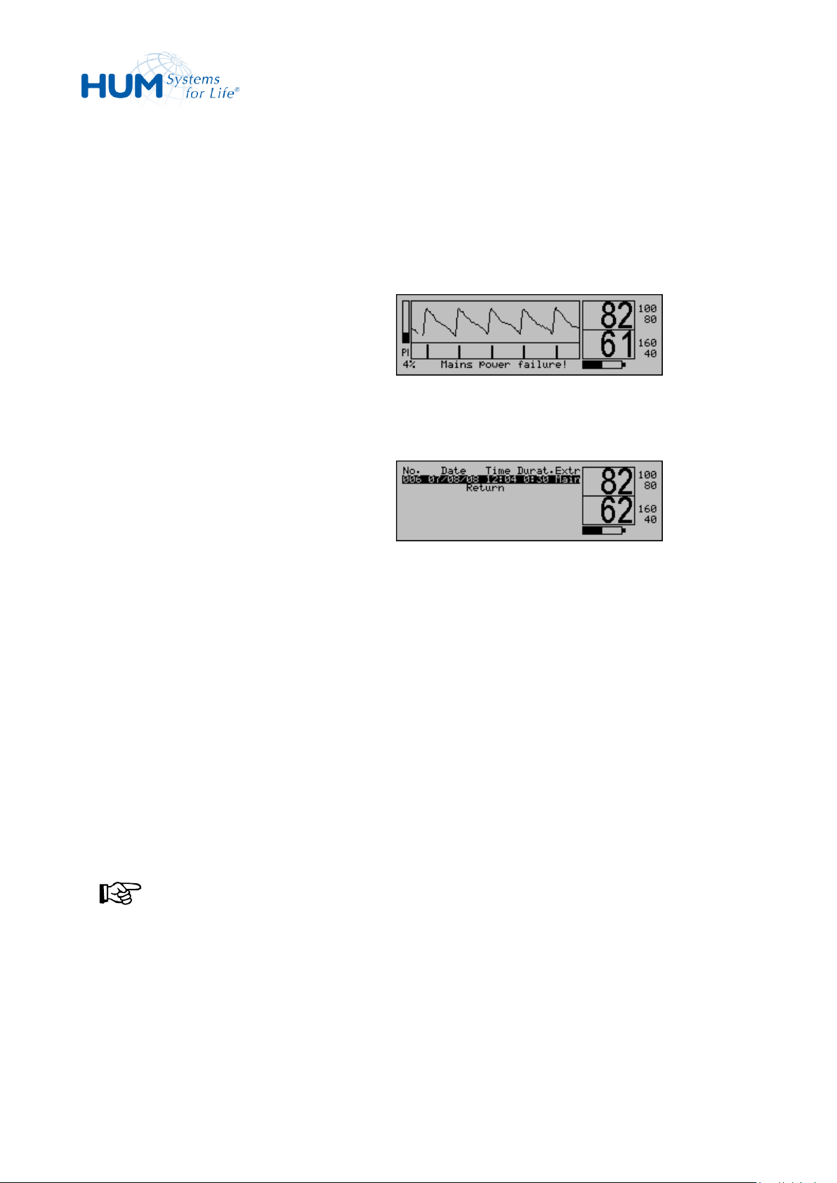
1. Approx. 5 sec. After mains failure, an
alarm (medium priority is triggered).
Fig. 11: Mains Power Failure Alarm
2. The mains power failure will generate a
corresponding entry into the alarm list.
3. After 30 seconds, the alarm will be
cancelled. The unit is now in battery
operation mode.
4. If the mains power supply is re-installed
in the course of the a.m. 30 seconds,
the mains power alarm will be
automatically reset.
NOTICE!
The Mains Power Failure condition is
displayed by the dark mains power LEDs.
Fig. 12: Mains Power Failure in Alarm List
6.3.1 Mains Power Failure Alarm
In case of a mains power failure, an alarm is triggered respectively. At the same time, the unit automatically
switches from mains to battery supply without any interruption.
31
Page 32
sat 805 Pulse Oximeter
Operation
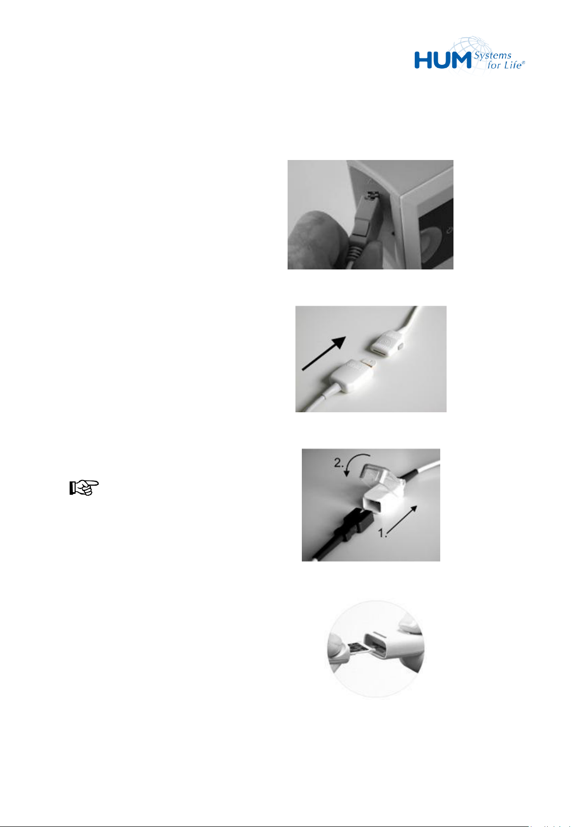
1. Connect the patient cable connector
into the unit socket.
The plug only fits in one direction and
audibly snaps in.
2. Select the required Masimo-Sensor, see
chapter 6.6.
3. Connect the sensor connector into the
patient cable connector. The plug only
fits in one direction and noticeably
snaps in.
NOTICE!
Some Masimo Sensors (e.g. type DCSC)
already have an integrated patient
cable. In this case, the connection to a
separated patient cable is omitted.
Fig. 13: Connect Patient Cable
Fig. 14: LNOP Sensor Connector
Fig.15: LNCS Sensor Connector
Fig. 16: RD SET Sensor Connector
6.4 Connections
6.4.1 Connecting the Patient Cable and Sensor
32
Page 33
sat 805 Pulse Oximeter
Operation
LNOP Sensors
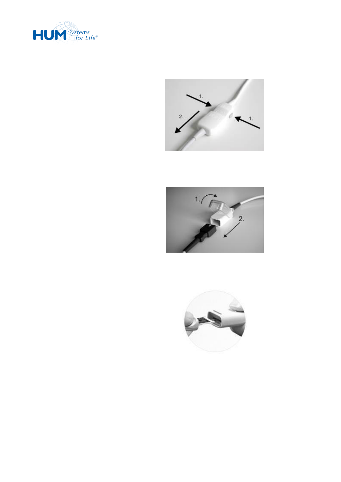
1. Press the two disconnect buttons (1)
together.
The locking mechanism unlocks the
sensor plug.
2. Remove the plug from the coupling (2).
Fig. 17: LNOP Sensor Coupling
LNCS Sensors
1. Lift the protective cover (1).
2. Pull firmly in the sensor connector to
remove from the patient cable (2).
Fig. 18: LNCS Sensor Coupling
RD SET Sensors
1. Pull firmly in the sensor connector to
remove from the patient cable.
Fig. 19: RD SET Sensor Coupling
6.4.2 Disconnecting the Sensor
33
Page 34
sat 805 Pulse Oximeter
Operation
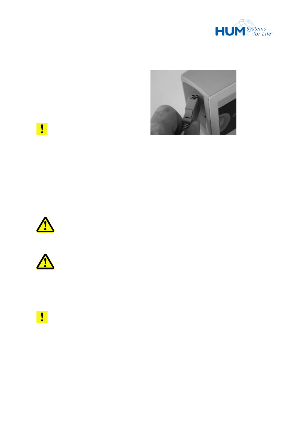
1. Press the two disconnect buttons (1) at
the patient cable socket together.
The locking mechanism unlocks the
patient cable.
2. Remove the connector.
ATTENTION!
Do not apply pressure when removing
the plug. It could be damaged.
Fig. 20: Patient Plug Coupling
6.4.3 Disconnecting the Patient Cable from the Unit
6.5 Installing the Unit
Install the unit in such a way so that it interferes with the patient’s mobility as little as possible. Under
normal circumstances, the unit should be positioned on the night table next to the patient’s bed.
WARNING! Danger from the Cable in Patient Vicinity!
When positioning the unit secure the cable line to avoid strangulation of the patient.
WARNING! Danger from Equalizing Current!
Never touch the patient and the external connections of the unit at the same time. The health of
the patient can be influenced from possible equalizing current occurrence.
ATTENTION! Unit can fall!
Secure the unit’s location. It can be damaged when falling or even injure the patient.
Never lift the unit by one of its connectors. They could be damaged.
Battery operation makes the unit portable.
34
Page 35

sat 805 Pulse Oximeter
Operation
WARNING! Connectors can disconnect during Movement!
When moving the unit during monitoring, absolutely ensure the correct position of the patient
connector. Should the connector accidentally become disconnected an alarm sounds.
6.6 Using Masimo-Sensors
CAUTION! Danger from not Observing User Instructions!
These sensors were developed only for usage of pulse oximeters with MasimoSET-technology.
The responsible organisation and/or the operator has to check the compability of the pulse
oximeter, cabel and sensor before every usage, otherwise this could cause dangerous injuries of
the patientPay attention to the notices in the user instruction manual for Masimo sensors. If not
observed the measurement results can be false.
Only use approved Masimo sensors with the unit. Use of other sensors can reduce the
performance capacity of the unit and thus produce danger to the patient!
Tissue damage can be caused by incorrect application or use of a sensor, for example by wrapping
the sensor too tightly. Inspect the sensor site as directed in the Instructions for Use to ensure skin
integrity and correct positioning and adhesion of the sensor.
Do not use damaged sensors or cables!
Do not use a sensor with exposed optical components.
The sensors as well as the patient cable connectors are not waterproof. Never immerse the
sensors or connecting elements in liquid or hold under running water.
Do not sterilize sensors and patient cable by irradiation, steam or ethylene oxide.
NOTICE!
More information on the use of Masimo sensors can be found in the user instructions of the
applicable sensor.
NOTICE!
A complete list of validated Masimo sensors will be provided on request by the manufacturer.
35
Page 36

sat 805 Pulse Oximeter
Operation
p/n
Sensor Type
Patient Type and Weight
Application Site
HPO04-ADTX
LNCS® Adtx
Adults > 30 kg
Ring- or Middle Finger of the
non-dominant Hand
HPO04-PDTX
LNCS® Pdtx
Children and Adults > 10 kg
and < 50 kg
Ring- or Middle Finger of the
non-dominant Hand
HPO04-INF
LNCS® Inf-L
Small Children > 3 kg < 20 kg
Great Toe or Thumb
HPO04-NEO
LNCS® Neo
Newborn, < 3 kg, adults > 40 kg
Foot, alternatively Back of the
Hand
HPO04-NEOPT
LNCS® NeoPt
Neonatal Preterms < 1 kg
Foot, alternatively Back of the
Hand
HPO05-ADT
RD SET Adt
Adults > 30 kg
Ring- or Middle Finger of the
non-dominant Hand
HPO05-PDT
RD SET Pdt
Children and Adults > 10 kg
and < 50 kg
Ring- or Middle Finger of the
non-dominant Hand
HPO05-INF
RD SET Inf
Small Children > 3 kg < 20 kg
Great Toe or Thumb
HPO05-NEO
RD SET Neo
Newborn, Children, Adults < 3 kg
or > 40 kg
Foot, alternatively Back of the
Hand
HPO05-NEOPT
RD SET NeoPt
Neonatal Preterms < 1 kg
Foot, alternatively Back of the
Hand
6.6.1 Selecting the (correct) Sensor
Select the sensor based on the patient’s age and weight and its re-usability. The Table is a guide. The
correct sensor has to be matched individually to the patient.
NOTICE!
The latest list of all sensors is directly available from HUM Gesellschaft für Homecare und
Medizintechnik mbH.
6.6.1.1 Adhesive Sensors
36
Page 37

sat 805 Pulse Oximeter
Operation
p/n
Sensor Type
Patient Type and Weight
Application Site
HPO02-DCSC
DCSC
Children and Adults > 30 kg, Spot
Check-Applications
Ring- or Middle Finger of the
non-dominant Hand
HPO04-DCI
LNCS® DCI
Children and Adults > 30 kg
Ring- or Middle Finger of the
non-dominant Hand
HPO04-DCIP
LNCS ®DCIP
Children and Adults > 10 kg and
< 50 kg
Ring- or Middle Finger of the
non-dominant Hand
HPO04-YI
LNCS® YI
Children and Adults > 1 kg
> 10 kg: Ring- or Middle Finger
of the non-dominant Hand.
> 3 kg < 10 kg: Great Toe.
< 3 kg: Foot, alternatively Back
of the Hand.
HPO04-TCI
LNCS® TC-I
Adults and Children > 30 kg,
Earsensor
Earlobe or Auricle
HPO04-TFI
LNCS® TF-I
Forehead Sensor, transflective,
Adults > 30 kg
Forehead
HPO05-DCI
RD SET DCI
Children or Adults > 30 kg
Ring- or Middle Finger of the
non-dominant Hand
HPO05-DCIP
RD SET DCIP
Children or Adults > 10 kg and
< 50 kg
Ring- or Middle Finger of the
non-dominant Hand
WARNING! Allergy Risk!
The use of Masimo and RD SET disposable SpO2-sensors is contraindicated on patients who
develop allergic reactions to the tape. The sensors must be re-positioned every 8 hours - and as
soon as lack of blood circulation or skin surface injury is displayed - remove them again and attach
them in another area.
6.6.1.2 Reusable Sensors
37
Page 38
sat 805 Pulse Oximeter
Operation
p/n
Model
Application
HPO04-K-PC04
LNC® -4
Patient Cable 1.2 m for LNCS® Sensors
HPO04-K-PC10
LNC® -10
Patient Cable 3.0 m for LNCS® Sensors
HPO05-K-PC05
RD SET MD14-05
Patient Cable 1.5 m for RD SET Sensors
HPO05-K-PC08
RD SET MD14-08
Patient Cable 2.4 m for RD SET Sensors
HPO05-K-PC12
RD SET MD14-12
Patient Cable 3.6 m for RD SET Sensors
WARNING! Danger with Long-Term Application!
The use of reusable Masimo and RD SET- sensors is contraindicated with long term application. These
sensors are not suitable for long-term monitoring. They must be attached every four hours - and as
soon as lack of blood circulation or skin surface injury is displayed - remove them and attach them in
another area.
6.6.1.3 Patient Cable
6.6.2 Expected lifetimes of patient cables and sensors
NOTICE!
X-CAL or lifetime related alarms, messages and information might not be present in all devices.
To confirm, please check in the product info menu (see chapter 7.7.6): only devices with DSP version
5.X.X.X will support the X-CAL related alarms and messages.
Both the Masimo patient cables and the sensors are equipped with lifetime counters. If 90% of this lifetime
is reached, the user is informed that the specified lifetime will be reached in the foreseeable future.
38
Page 39

sat 805 Pulse Oximeter
Operation
Sensor / Cable
Active Patient
Monitoring Limit
Duration if
Monitoring 24
Hours Per Day
Duration if
Monitoring 12
Hours Per Day
Duration if
Monitoring 8
Hours Per Day
Single-patient-use
SpO2-Sensors with
replaceable tape
336 hours
14 days
28 days
42 days
Single-patient-use
SpO2-Sensors without
replaceable tape
168 hours
7 days
14 days
21 days
Reusable SpO2-Sensors
(DCI, DCIP, YI, TC-I, TF-I,
and DBI)
8760 hours
12 months
24 months
36 months
Patient Cables
17520 hours
24 months
48 months
72 months
Sensor / Cable
Remaining time at 90%
Single-patient-use SpO2-Sensors with
Replaceable tape
ca. 34 hours
Single-patient-use SpO2-Sensors without
Replaceable tape
ca. 17 hours
ReusableSpO2-Sensors
(DCI, DCIP, YI, TC-I, TF-I, and DBI)
ca. 876 hours
Patient Cables
ca. 1752 hours
The lifetimes are defined as follows:
6.6.2.1 90%-Lifetime or „Near expiration“-message
39
Page 40
sat 805 Pulse Oximeter
Operation
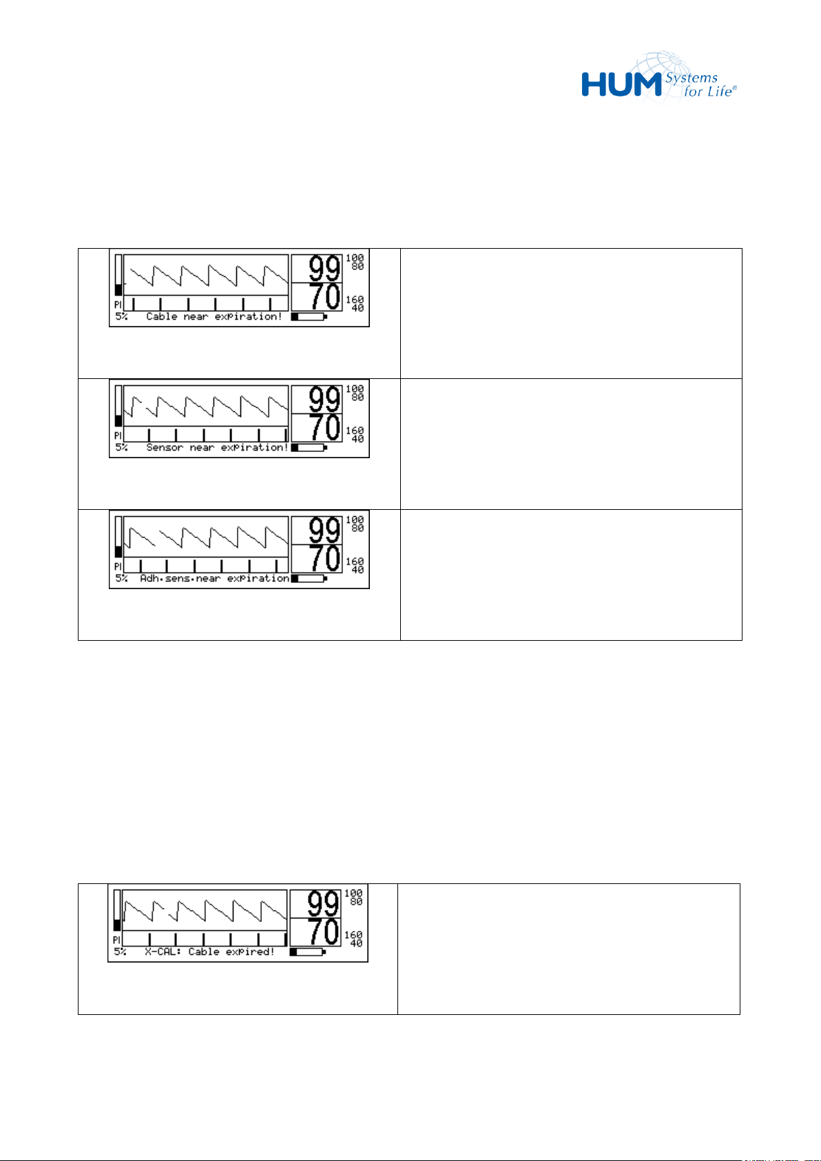
Fig. 21: Cable near expiration
Technical message:
„Cable near expiration“
Fig. 22: Sensor near expiration
Technical message:
„Sensor near expiration“
Fig. 23: Adh. sensor near expiration
Technical message:
„Adh. sensor near expiration“
Fig. 24: X-CAL: Cable expired
Technical message:
„X-CAL: Cable expired“
The following technical messages are output when 90 % of the specified service life of the patient cable or
sensor is reached.
6.6.2.2 Life time exceeded
If the life time of the accessories is reached during monitoring operation, the technical message "Service
life reached" is output.
Exceeding this threshold triggers a further period of time: the so-called "extension phase". This is 12 hours
for single-patient adhesive sensors and 72 hours for reusable sensors.
In this phase, the accessories can still be used for the current monitoring, but may be before a switch-off
with a sensor-defective message.
40
Page 41
sat 805 Pulse Oximeter
Operation
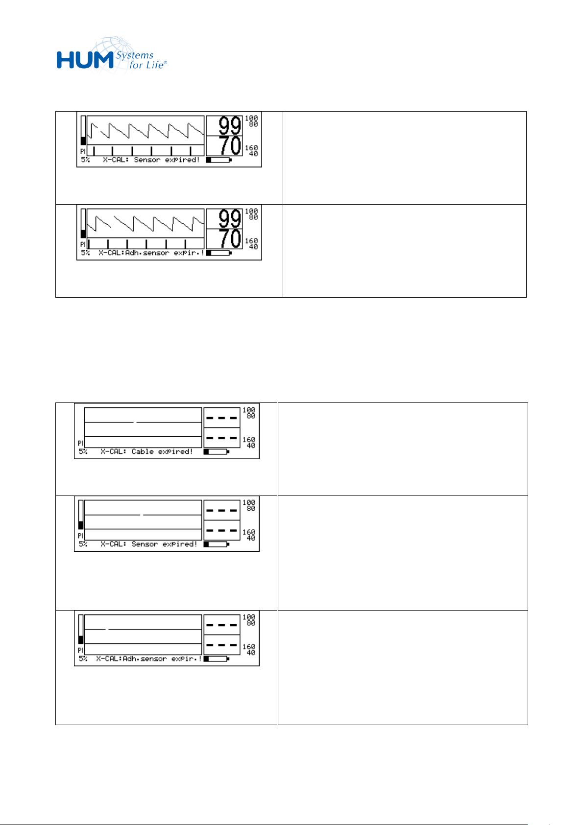
Fig. 27: Cable expired expiration
High priority alarm
“Cable expired” & “Sensor not on
patient”
Fig. 28: Sensor expired
High priority alarm
“Sensor expired” & “Sensor not on
patient”
Fig. 29: Adh.Sensor expired
High priority alarm
“Adh.Sensor expired” & “Sensor not on
patient”
Fig. 25: X-CAL: Sensor expired
Technical message:
„ X-CAL: Sensor expired“
Fig. 26: X-CAL: Adh. sensor expired
Technical message:
„ X-CAL: Adh. sensor expired“
In contrast to sensors, a patient cable is never switched off after its service life has been reached.
If a sensor alarm is triggered during the extension phase (e.g. sensor not on the patient), it is displayed
together with this as a high-priority alarm.
41
Page 42
sat 805 Pulse Oximeter
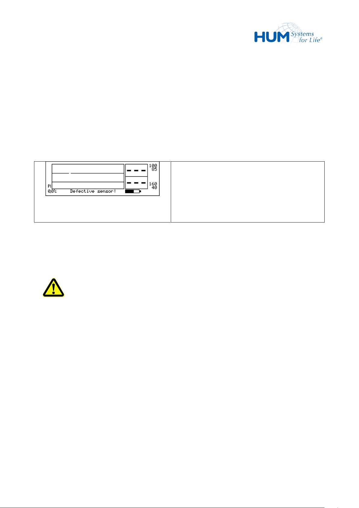
Fig. 30: Defective sensor
High priority alarm
“Defective sensor” (beyond lifetime)
After the cause of the alarm has been eliminated, this alarm is downgraded again to the technical message
"Sensor expired".
If, on the other hand
1. the sensor-pulse oximeter connection is disconnected or
2. longer than 2 hours the sensor would not have been on the patient or
3. a device reset (e.g. by a restart) is performed,
the sensor is immediately switched as defective (alarm: defective sensor) and further use is impossible.
6.7 Using the Interfaces
The interfaces on the device may be operated and installed by trained personnel only. Connecting the
analog or nurse call interface via the interface connector is only allowed upon instruction of these persons.
WARNING! Danger by improper Application of the Interface!
If non-specified devices are connected to the interfaces of the device, there may be health-related
injuries of the patient caused by equalizing or leakage currents.
For assuring a complete patient insulation, connect electrically isolated devices only.
42
Page 43
sat 805 Pulse Oximeter
Control
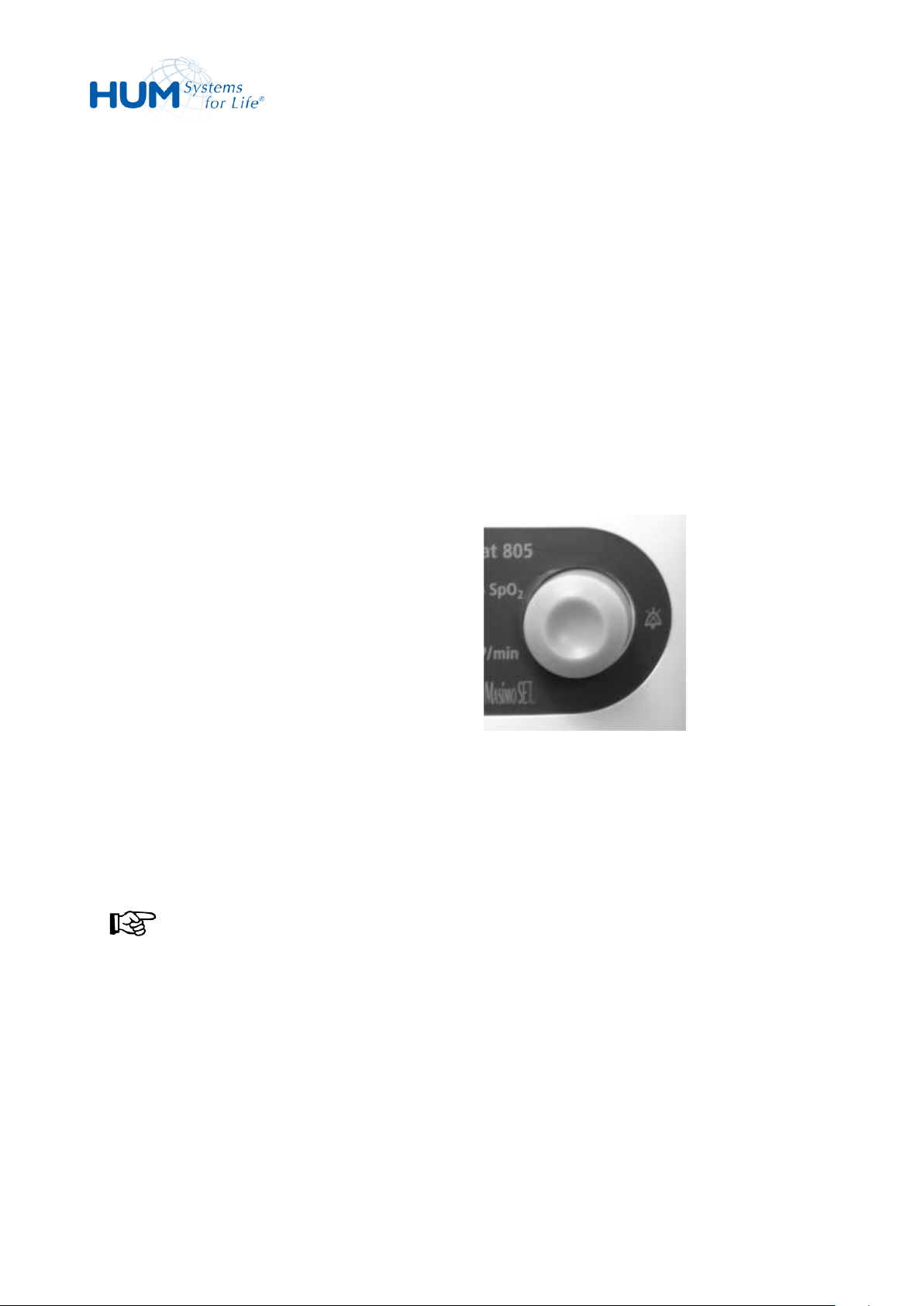
Operation of the menu by the trim knob:
1. Turning clockwise: up, page up and
increase values
2. Turning counter-clockwise: down, page
down and decrease values
3. Short push (< 1 sec): confirm setting or
activate acoustical alarm mute function
(active alarm)
4. Long push (> 1 sec): enable / disable
acoustical alarm mute function
(independent of active alarm)
Fig. 31: Trim Knob
7 Control
7.1 General
Control of the unit takes place on the LCD-display in combination with the trim knob.
In the directional text of this user manual, the texts, appearing in the display, are highlighted to assist in
understanding. In addition, the following writing format is used: “Display text.”
7.2 Menu Operation
7.2.1 Using the Trim Knob
NOTICE!
If you do not confirm or accept a menu setting within 60 seconds of making it by pressing the trim
knob, the standard screen is automatically displayed.
43
Page 44
sat 805 Pulse Oximeter
Control
1. Press the trim knob.
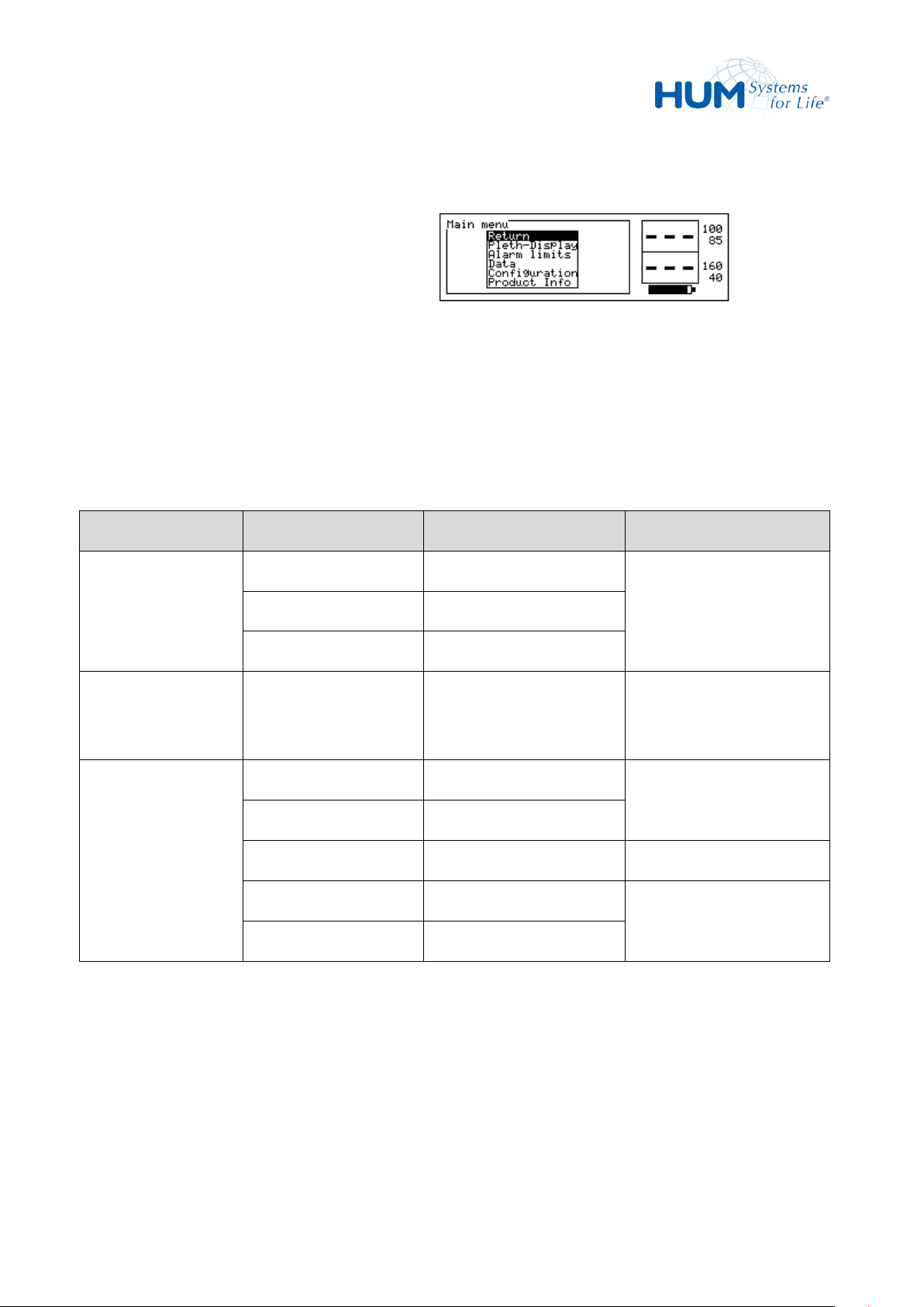
2. The main menu is displayed in the LC
display.
Fig. 32: Main Menu
Level 1
Level 2
Level 3
Remark
Pleth-Display
without pleth.
Configuration of the LC
display
compressed
stretched
Alarm limits
Setting the alarm limits
and alarm filter
parameters
Data
Vital alarm list
Alarm lists
Total alarm list
Trend
On-screen data display
Memory config.
Memory configuration
Erase Memory
7.2.2 Calling the Main Menu
7.2.3 Menu Structure
After selecting a menu item further menu items can be selected subsequently. Therefore in some cases it is
necessary to select several menu items one after the other before the final setting can be made.
The menu structure is as follows:
44
Page 45

sat 805 Pulse Oximeter
Control
Level 1
Level 2
Level 3
Remark
Configuration
Acoust. Alarms
Volume pulse
Configuration of the
Volume alarm
acoustical alarms
Silence Time
Signal process
Algorithm mode
Setting of pulse oximetry
parameters
Averaging time
SmartTone
Artifact-filter
Screen
Contrast
Adjustment of the LC
screen options
Backlight
Language
Home mode
Nurse call
Configuration of the
external alarm interface
Analogue out
Calibration signals
Clock
Setting the system time
Product Info
Overview of the device
settings
7.3 Switching on the Unit
45
Page 46
sat 805 Pulse Oximeter
Control
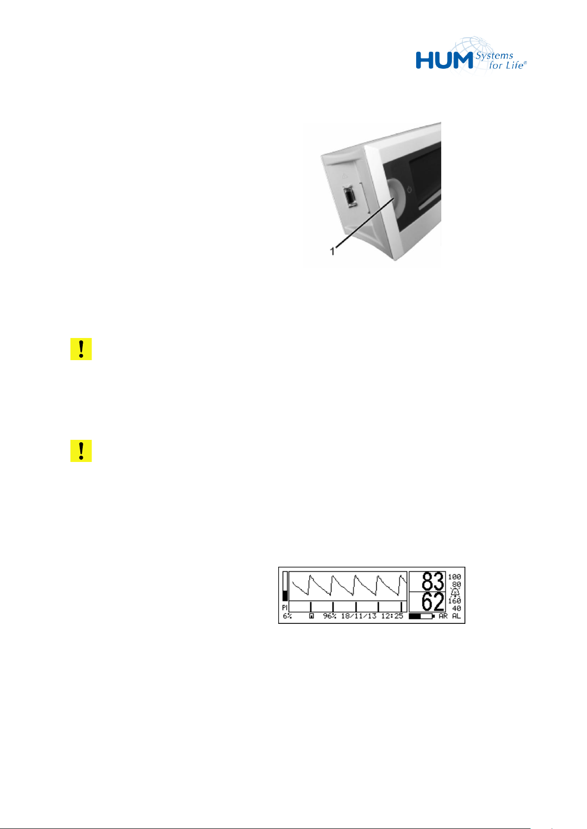
1. Press ON/OFF button (1).
2. A signal sound activates.
3. An optical, audio, and internal self
examination is completed:
– The LEDs are activated.
– A dark and bright test picture
appears briefly on the LC display.
– A short alarm signal is issued.
The unit goes through extensive
internal hardware testing.
Fig. 33 Switching on
4. After this the Normal Display
appears.
Now the signal search for the pulse
occurs (blinking dashes and sensor
symbol). With a successful pulse search
the measured values for oxygen
saturation and pulse frequency are
displayed on the LCD screen.
Fig. 34: Normal Display
ATTENTION! Unsuccessful Tests!
If one or several tests are not successfully executed, a corresponding error message is displayed in
the display.
The unit can and may not be used on patients.
ATTENTION! Defective Alarm Loudspeaker!
If the alarm loudspeaker is defective, a replacement signal generator is activated internally. This
does not take over the full functionality of the alarm loudspeaker (volume, tone sequences).
The device must then not be used on the patient!
46
Page 47
sat 805 Pulse Oximeter
Control
NOTICE!
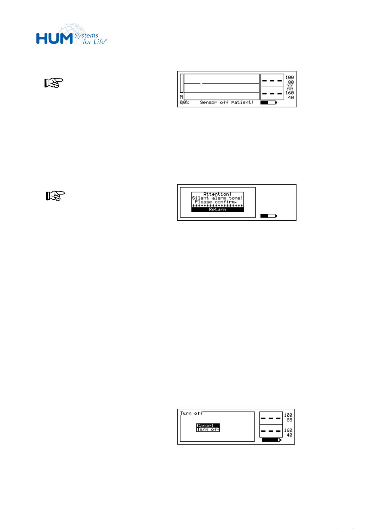
In case the Masimo sensor is not
connected or not correctly on the
patient, a corresponding error message
is displayed, e.g. "Sensor off
Patient!".
In addition an alarm sound is heard.
Fig. 35: Sensor off Patient!
NOTICE!
If the alarm tone volume setting is 5 or
less, a warning message is displayed
during the power-up cycle.
The operator has to acknowledge this
setting with OK.
Otherwise, the device will not enter the
standard mode but will be switched off
automatically.
5. Now the unit is operational.
Fig. 36: Silent Alarm Tone!
1. Press the ON/OFF-button.
2. The power-down menu is displayed in
the LC display.
3. With the trim knob, select Turn off
and confirm.
Fig. 37: Power-Down Menu
7.4 Turning the Unit off
The turn-off process is designed so that turning it off accidentally can possibly be avoided. After turning off
the unit all previously entered values and configurations are preserved.
Except for the settings „Alarm tone loudness = 0 (OFF)“ and „algorithm“ the minimum audible =1 and
=“Norm.Perfus.“ is returned.
To turn the unit OFF:
47
Page 48
sat 805 Pulse Oximeter
Control
NOTICE!
Should the ON/OFF process be
interrupted the last readings before the
ON/OFF process appear for approx.
5 seconds. The monitoring remains intact
for the entire time.
4. The unit is now being turned off.
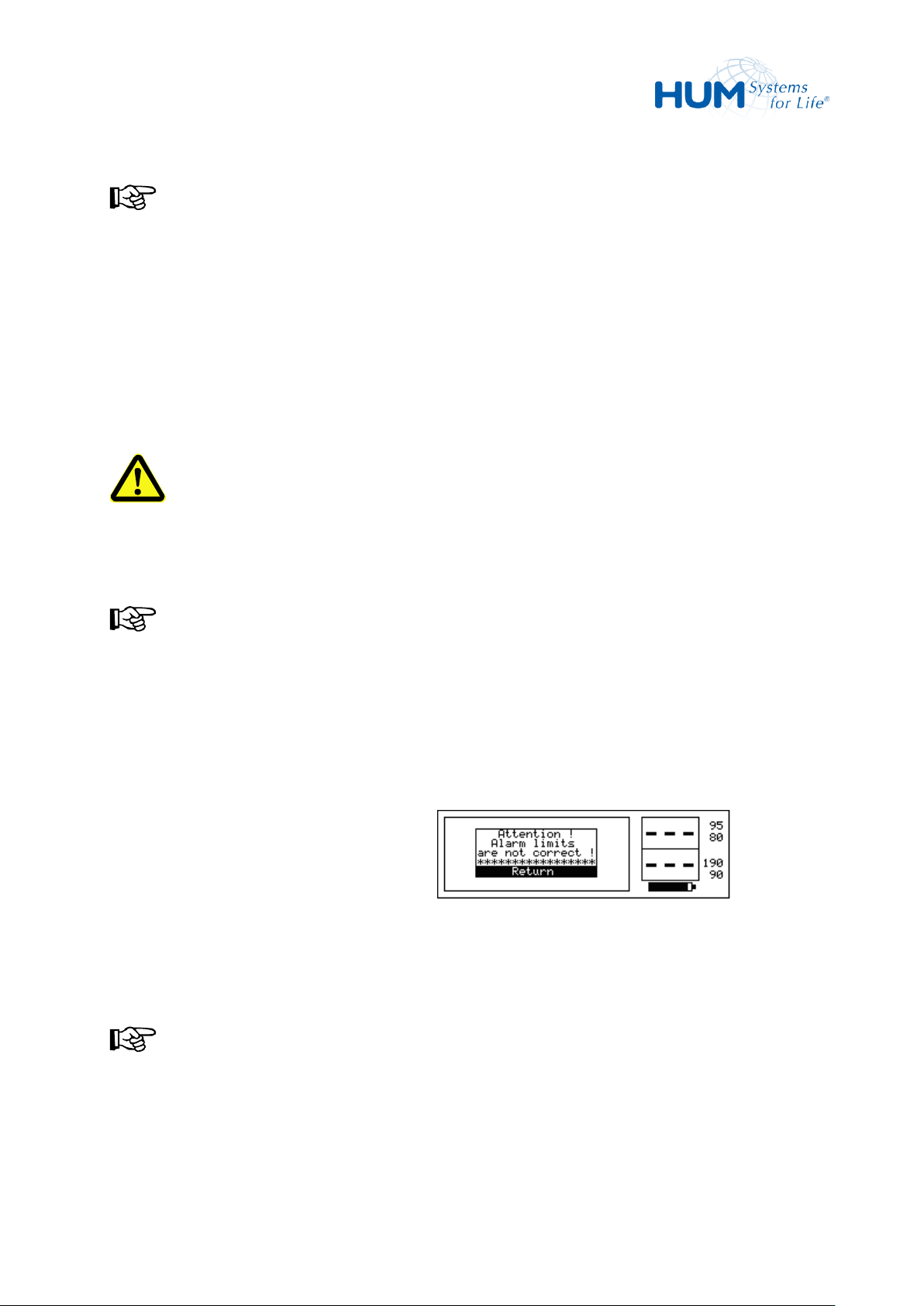
If implausible alarm limits are set (e.g. the
lower limit value is greater than the higher
value), the device responds with the error
message “Alarm limits are not
correct!“ .
In this case, the alarm limits selected are not
accepted as new values.
NOTICE!
The difference between the upper and
lower alarm limit values must, to be
plausible, be at least two units.
Fig. 38: Alarm Limits not correct
7.5 Alarm Limits (Alarm limits)
WARNING! Incorrectly set alarm limits endanger risk of non-alerting!
Changing the alarm settings is a serious intervention in the device functions and must never be
done without first consulting the doctor in charge of the treatment!
NOTICE!
Until the modified alarm limit value has been accepted, the most recently stored value remains in
force.
If the alarm limit modification procedure is interrupted or cancelled, this value persists.
The saved limits remain also after a complete loss of the voltage.
48
Page 49
sat 805 Pulse Oximeter
Control
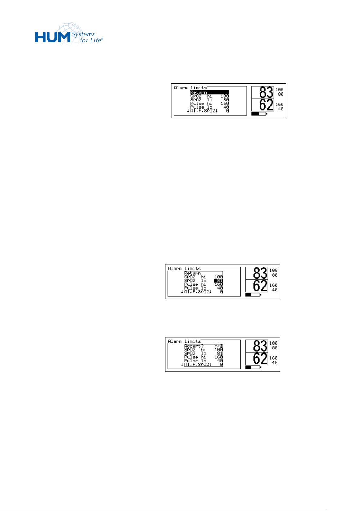
1. Starting from the normal display, call:
Alarm limits
2. Select SpO2 hi, for setting the upper
SpO2 alarm limits,
or
select SpO2 lo, for setting the lower
SpO2 alarm limit
Select Pulse hi, for setting the upper
pulse rate alarm limit,
or
select Pulse lo, for setting the lower
pulse rate alarm limit.
3. Select the alarm limits to be changed by
pressing the trim knob.
4. Set the new value by turning the trim
knob.
5. Confirm the new value by pressing the
trim knob.
6. Set other values if needed.
7. Leave the menu with Return.
8. Confirm all new values by confirming
the safety question Accept? Y/N.
Fig. 39: Alarm Limits
Fig. 40: Modifying the Alarm Limits
Fig. 41: Confirming the Alarm Limits
7.5.1 Setting the Alarm Limits
49
Page 50

sat 805 Pulse Oximeter
Control
1. Starting from the normal display, call:
Alarm limits
2. Select Al.F.SpO2 , for setting the
alarm filter period for the lower SpO2
alarm limit,
or
select Al.F.Pulse for setting the
upper pulse rate limit.
Fig. 42: Alarm Limits
7.5.2 Setting the Alarm Filter
WARNING! Incorrectly set alarm limits endanger risk of non-alerting!
Activating or changing the alarm filter settings is a serious intervention in the device functions and
may never be done without consulting the doctor in charge of the treatment!
For canceling short and therefore irrelevant alarm conditions, an alarm filter can be set.
no alarm filter with alarm filter
The alarm filter produces a “silent alarm”. During the set alarm filter time period (adjustable between
0=OFF and 20 seconds maximum), the occurence of an alarm condition for oxygen saturation and/or pulse
rate will NOT lead to an acoustical nor optical alarm. After the above mentioned alarm filter time period,
the alarm will be generated. If in the meantime the source of the alarm condition will vanish, there will be
no alarm at all.
The alarm filters can be configured individually for SpO2 low and also for pulse rate high.
This feature will increase user compliance by suppressing short alarm periods.
The alarm filters are deactivated when shipped from the factory. (0=OFF)
50
Page 51
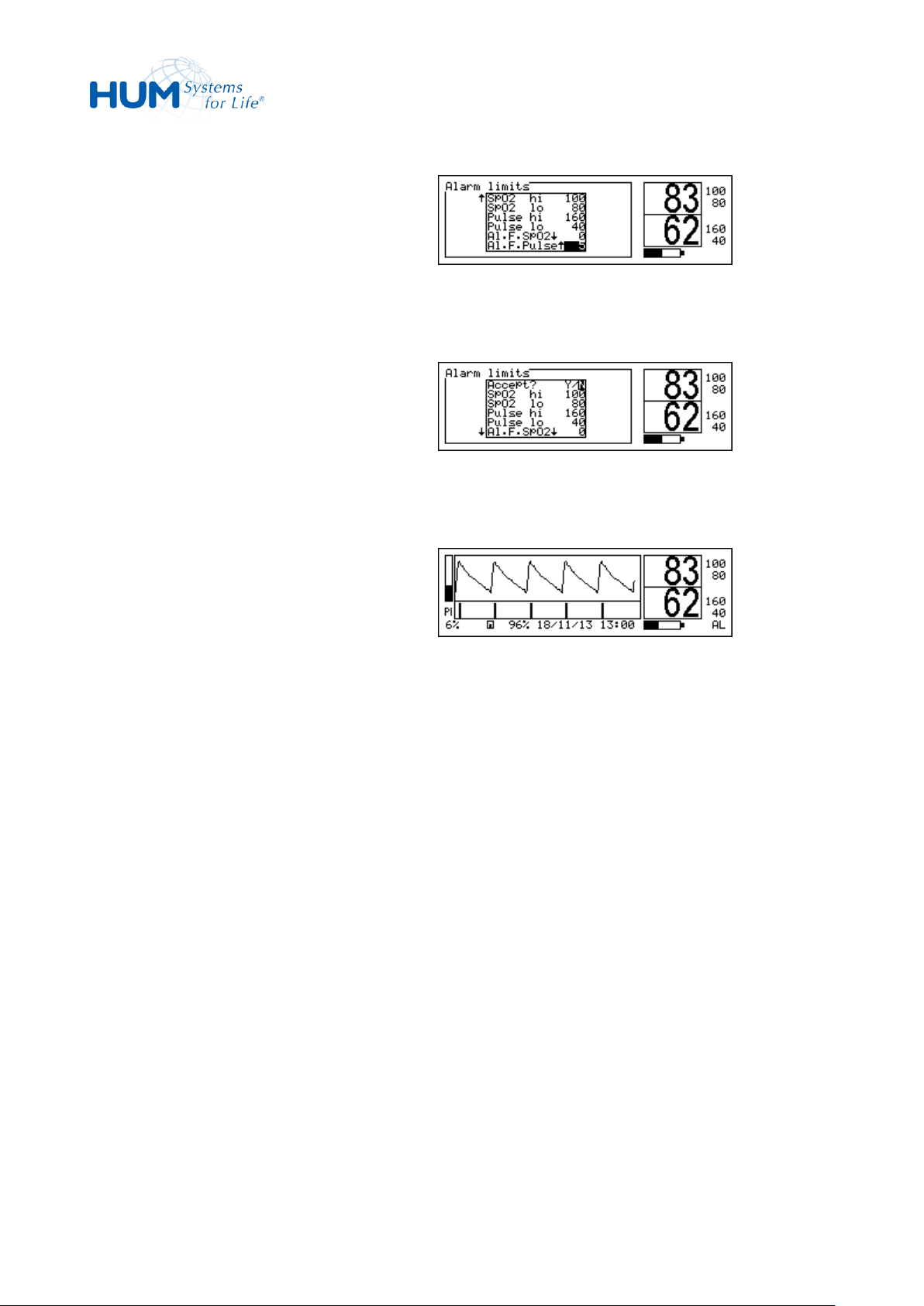
sat 805 Pulse Oximeter
Control
3. Select the alarm filter to be changed by
pressing the trim knob.
4. Set the new period (in seconds) value by
turning the trim knob.
5. Confirm the new value by pressing the
trim knob.
6. Set other values if needed.
7. Leave the menu with Return.
8. Confirm all new values by confirming
the safety question: Accept? Y/N.
9. If the alarm filter is activated, this will
be displayed by the symbol AL in the
lower right area of the display.
Fig. 43: Modifying the Alarm Filter
Fig. 44: Confirming the Settings
Fig. 45: Status Symbol „AL“
51
Page 52
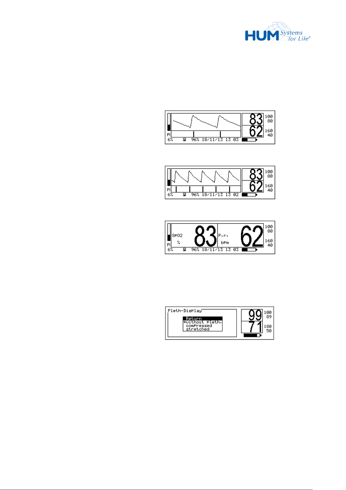
sat 805 Pulse Oximeter
Control
1. Stretched, normalized plethysmogram
Fig. 46: Plethysmogram, stretched
2. Compressed, normalized
plethysmogram
Fig. 47: Plethysmogram, compressed
3. Big numbers only – without
plethysmogram
Fig. 48: Number Display
1. Starting from the main menu, select:
Pleth-display
2. Select the display mode by turning the
trim knob.
3. Confirm the setting by pressing the trim
knob.
4. Return to the main menu by selecting
Return.
Fig. 49: Plethysmogram Display
7.6 Plethysmogram Display (Pleth-display)
In this menu, the display is configured.
Following modes are available:
For configuration of the display:
52
Page 53
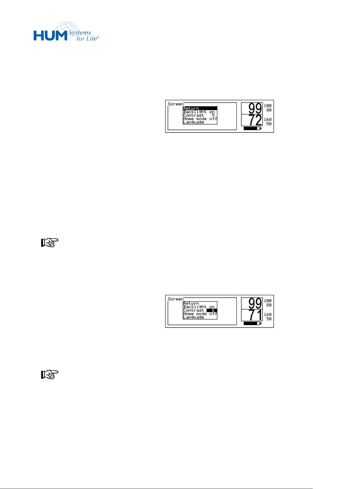
sat 805 Pulse Oximeter
Control
1. Starting from the main menu, call:
Configuration Screen
2. Select
Backlight, Contrast, Home
mode or Language
3. Confirm the selection by pressing the
trim knob.
Fig. 50: Screen
1. Starting from the main menu, call:
Configuration Screen
Contrast
2. Adjust the contrast by turning the trim
knob.
The contrast is represented by a figure
between 1 und 10.
NOTICE!
The changes made will be shown in the
settings.
3. Confirm the selection by pressing the
trim knob.
Fig. 51: Contrast Setting
7.7 Configuration (Configuration)
7.7.1 Screen options (Screen)
7.7.1.1 Contrast (Contrast)
The functions adjust the contrast setting of the LC display.
The contrast can be adjusted between values of 1 and 10.
NOTICE!
The contrast setting will depend on external environmental conditions such as the prevailing amount
of light and the angle when reading the device.
53
Page 54
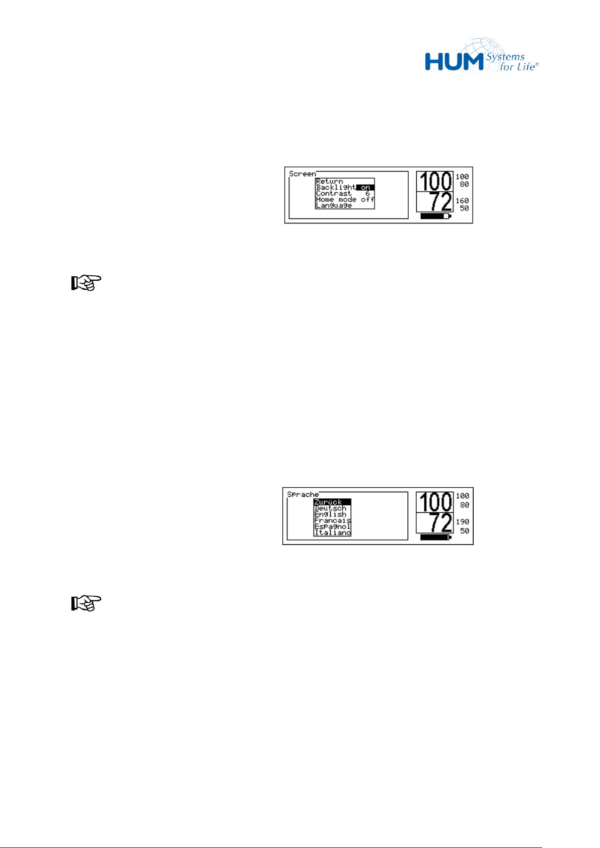
sat 805 Pulse Oximeter
Control
1. Starting from the main menu, call:
Configuration Screen
Backlight
2. Adjust the setting ON/OFF by turning
the trim knob.
NOTICE!
The changes made will be shown in the
settings.
3. Confirm the selection by pressing the
trim knob.
Fig. 52: Backlight
1. Starting from the main menu, call:
Configuration Screen
Language
2. Select the desired language by turning
the trim knob.
NOTICE!
The changes made will be shown in the
settings.
3. Confirm the selection by pressing the
trim knob.
Fig. 53: Language
7.7.1.2 Backlight (Backlight)
This function activates the LCD backlight; settings are “ON” and “OFF”.
7.7.1.3 Menu Language (Language)
This function sets the menu language.
54
Page 55
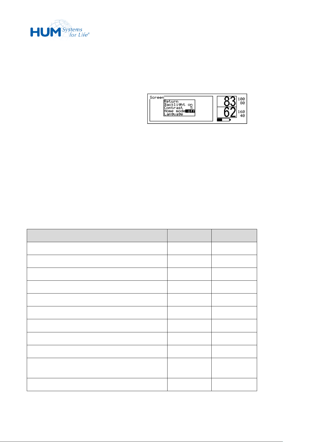
sat 805 Pulse Oximeter
Control
Following access permissions may be set:
– HomeCare Mode ON (Home
Mode ON)
– HomeCare Mode OFF (Home
Mode OFF)
Fig. 54: Access Permissions
Access Permissions
HomeCare ON
HomeCare OFF
Pleth-Display
+
+
Alarm Limits - +
Alarm Filter - +
Vital Alarm List
+
+
Total Alarm List
+
+
Trend + +
Memory Config.
-
+
Erase Memory
-
+
Volume Puls + +
Volume Alarm
+/- (OFF is not
available)
+
Silence Time + +
7.7.1.4 Access Permissions (Home Mode)
Starting from the main menu, call:
Configuration Home Mode
– The “HomeCare mode ON” access protects the inexperienced user from modifying important
monitoring parameters. These parameters are invisible.
– The “HomeCare mode OFF” access allows users to set all the configuration parameters.
55
Page 56
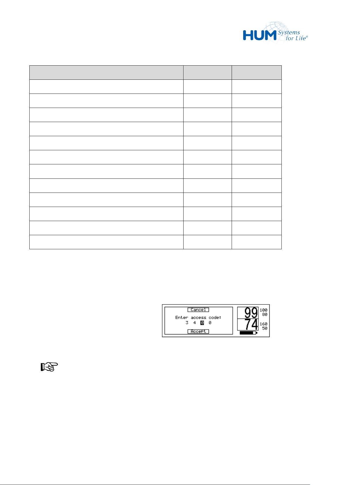
sat 805 Pulse Oximeter
Control
Access Permissions
HomeCare ON
HomeCare OFF
Algorithm Mode
-
+
Averaging Time
-
+
SmartTone - +
Artifact-Filter
-
+
Backlight + +
Contrast + +
Home Mode (Access permission)
+
+
Language + +
Nurse Call - +
Analog out - +
Clock - +
Product Info + +
- = not allowed
+ = allowed
1. Starting from the main menu, call:
Configuration Screen
Home Mode ON/OFF
2. Enter the four-digit pin code for the
respective access permission.
NOTICE!
The pin code is located in a separate
document.
In case call the manufacturer.
3. Select the first digit with the trim knob.
Fig. 55: PIN Code Entry
Setting the Access Permission:
56
Page 57
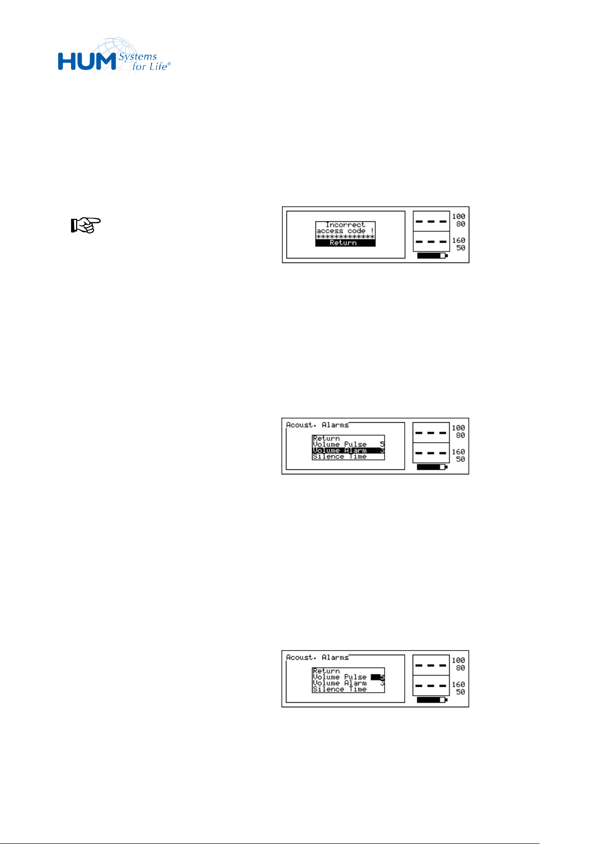
sat 805 Pulse Oximeter
Control
4. Set the correct number.
5. Repeat steps 3 and 4 until the complete
code is entered.
6. Confirm the code by selecting Accept.
NOTICE!
An invalid access code is answered by
the error message: "Incorrect
access code! “ Re-enter the correct
code.
Fig. 56: Invalid Access Code
Following settings can be adjusted:
– Pulse tone volume (Volume Pulse)
– Alarm tone volume (Volume Alarm)
– Alarm tone mute time (Silence
Time)
Fig. 57: Acoustical Alarm
1. Starting from the main menu, call:
Configuration Acoust.
Alarms Volume Pulse
2. Adjust the pulse tone volume with the
trim knob from OFF to loud (10).
Fig. 58: Pulse Tone Volume
7.7.2 Acoustical Alarms (Acoust. Alarms)
Starting from the main menu, call:
Configuration Acoustic. Alarms
7.7.2.1 Pulse Tone Volume (Volume Pulse)
When the pulse signal tone is activated, then in monitoring mode a tone signal will be played for every
detected pulse. The pitch of the tone identifies the current oxygen saturation. In other words, the higher
the pitch of the tone, the greater is the measured oxygen saturation (and vice versa).
57
Page 58
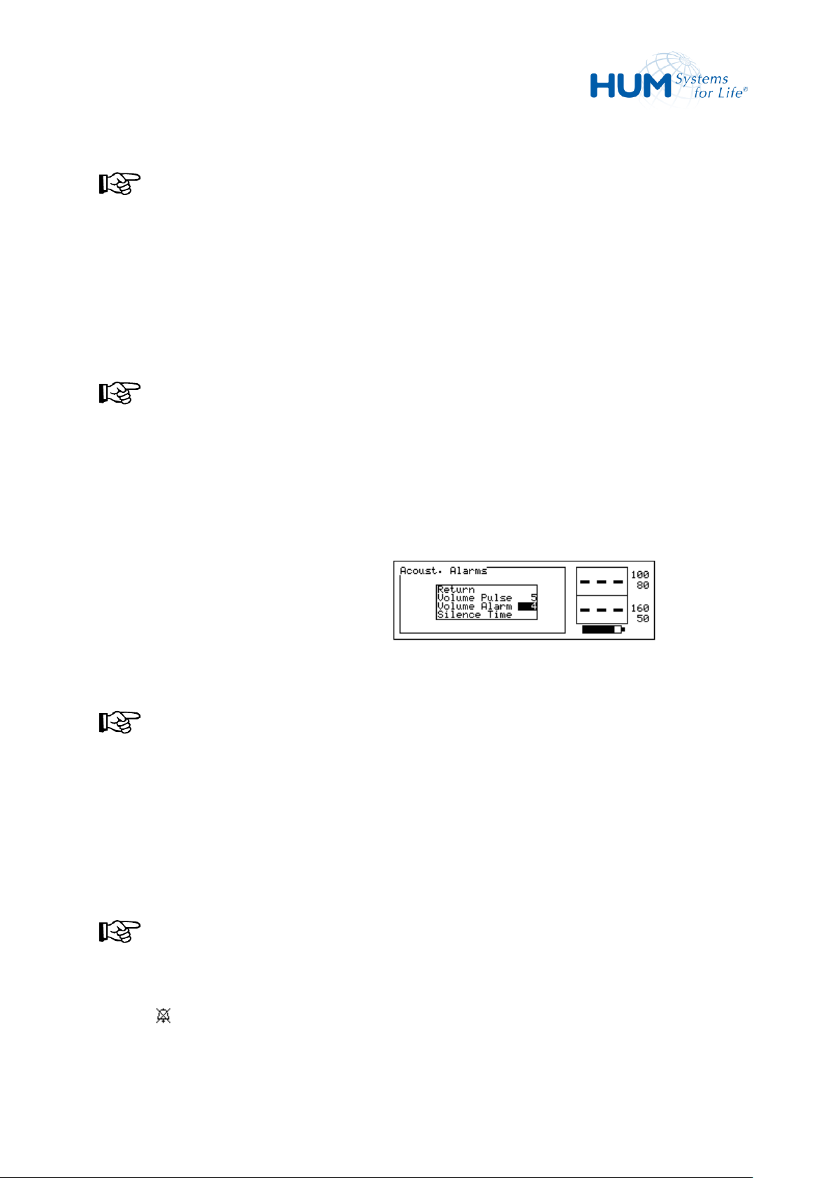
sat 805 Pulse Oximeter
Control
NOTICE!
Every incremental change emits the
actual volume strength once.
3. Confirm this setting by pressing the trim
knob.
NOTICE!
This de-activation of the pulse signal
tone is not shown on the display.
1. Starting from the main menu, call:
Configuration Acoust.
Alarm Volume Alarm
2. Adjust the alarm tone volume with the
trim knob between OFF and loud (10).
NOTICE!
Every incremental change emits the
actual volume strength once.
3. Confirm this setting by pressing the trim
knob.
NOTICE!
If you select the OFF setting, the display
shows the permanent alarm silence
symbol: .
Fig. 59: Alarm Tone Volume
7.7.2.2 Alarm Tone Volume (Volume Alarm)
58
Page 59
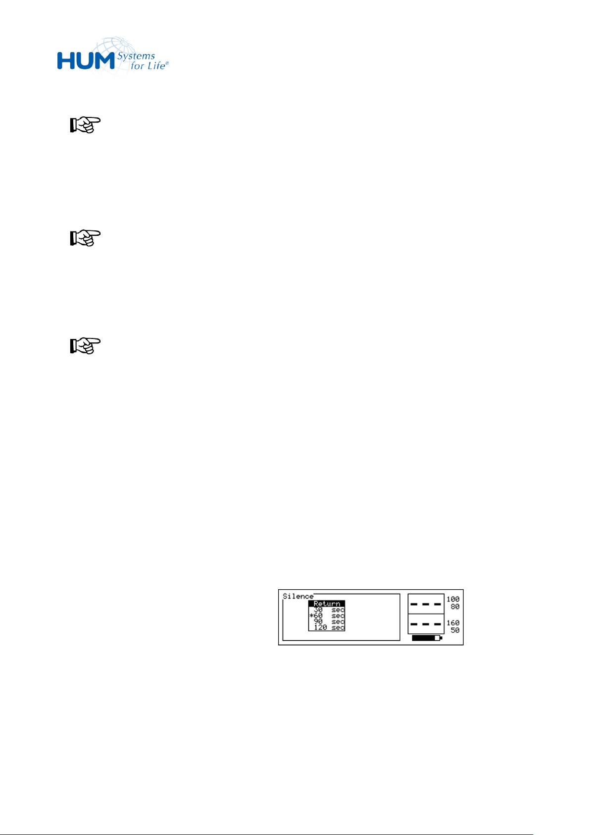
sat 805 Pulse Oximeter
Control
NOTICE!
If you select a setting of less than 5, a
warning message is displayed during
the next power-on cycle reminding the
operator at a possibly too silent setting.
NOTICE!
An alarm volume of <1 is not stored
permanently. The alarm volume will be
set during the next power-on cycle to a
minimal non-zero value = 01.
NOTICE!
In Home Care Mode, audio mute
setting (=OFF) is not possible.
1. Starting from the main menu, call:
Configuration Acoust.
Alarms Silence Time
2. Set the alarm tone silence time between
30 and 120 sec using the trim knob
(the selection is displayed by *).
3. Confirm this setting with Return.
Fig. 60: Alarm Tone Silence Time
7.7.2.3 Alarm Silence Time (Silence Time)
The alarm signal mute time displays the duration of the mute signal, if the alarm signal mute time has been
set and acknowledged.
After expiration of this time the sound alarm is activated again, if the acknowledged alarm condition still
exists.
The alarm signal mute time can be set between 30, 60, 90, and 120 seconds.
59
Page 60
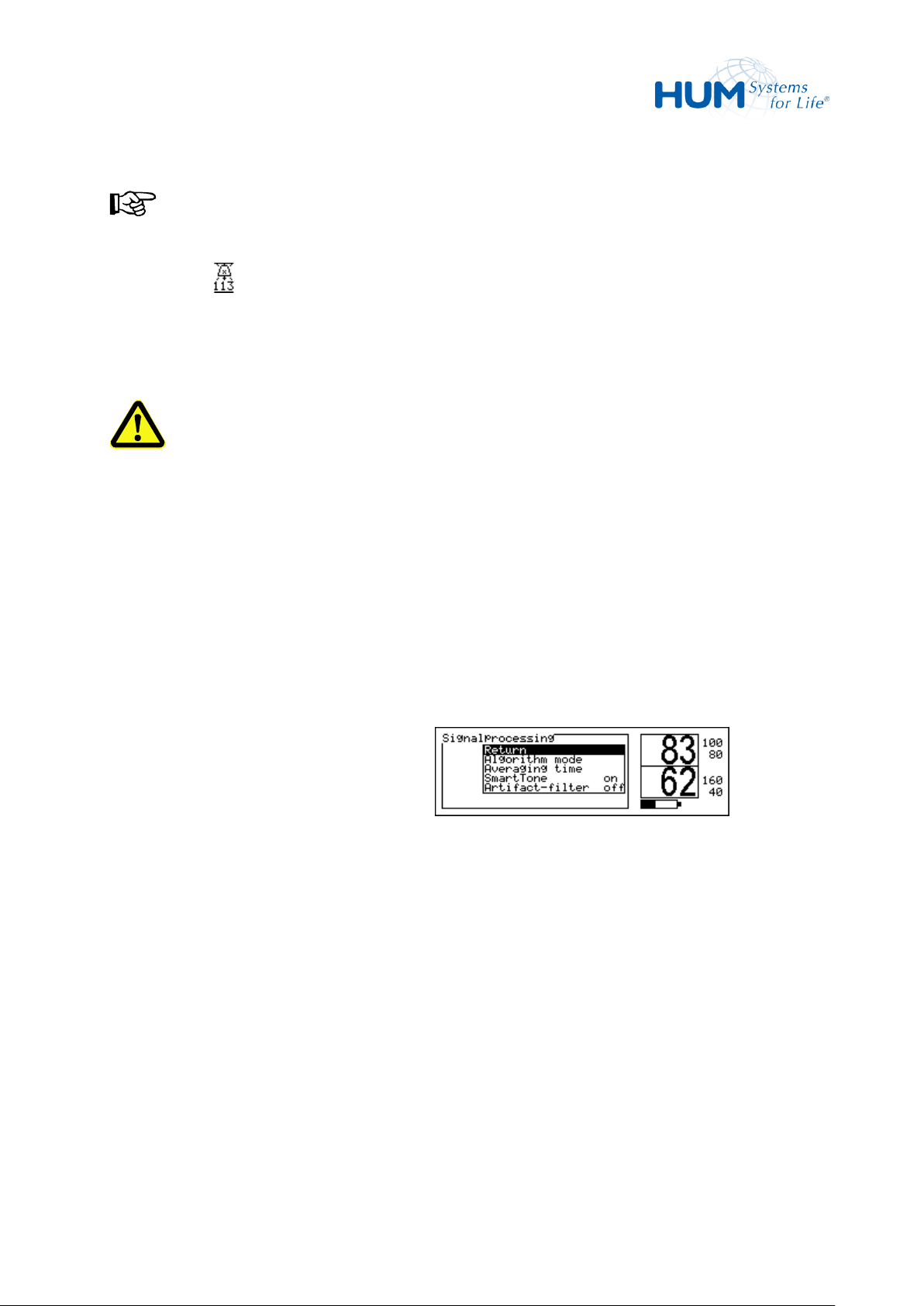
sat 805 Pulse Oximeter
Control
NOTICE!
During the alarm silence time, the alarm
silence symbol appears to indicate
that the option is active (the number
below shows the remaining time in
seconds).
Following actual signal processing parameters
can be set:
– Averaging time (Averaging time)
– Sensitivity (Algorithm mode)
– Smart Tone (ON/OFF)
– Artifact-filter (ON/OFF)
Fig. 61: Masimo Signal Processing
WARNING! New alarms cannot be detected!
If a new alarm condition occurs during the alarm tone mute duration, the new alarm will be
displayed after completion of the mute duration.
7.7.3 Masimo Signal Processing (Signalprocessing)
Starting from the main menu, call:
Configuration Signalprocessing
7.7.3.1 Averaging Time (Averaging time)
The averaging time indicates the duration, with which from several original measured values individual
displays one VALUE is again computed.
The averaging time can be adjusted between 2-4 (FastSatTM) and 16 seconds. 8 seconds is the default
setting.
60
Page 61
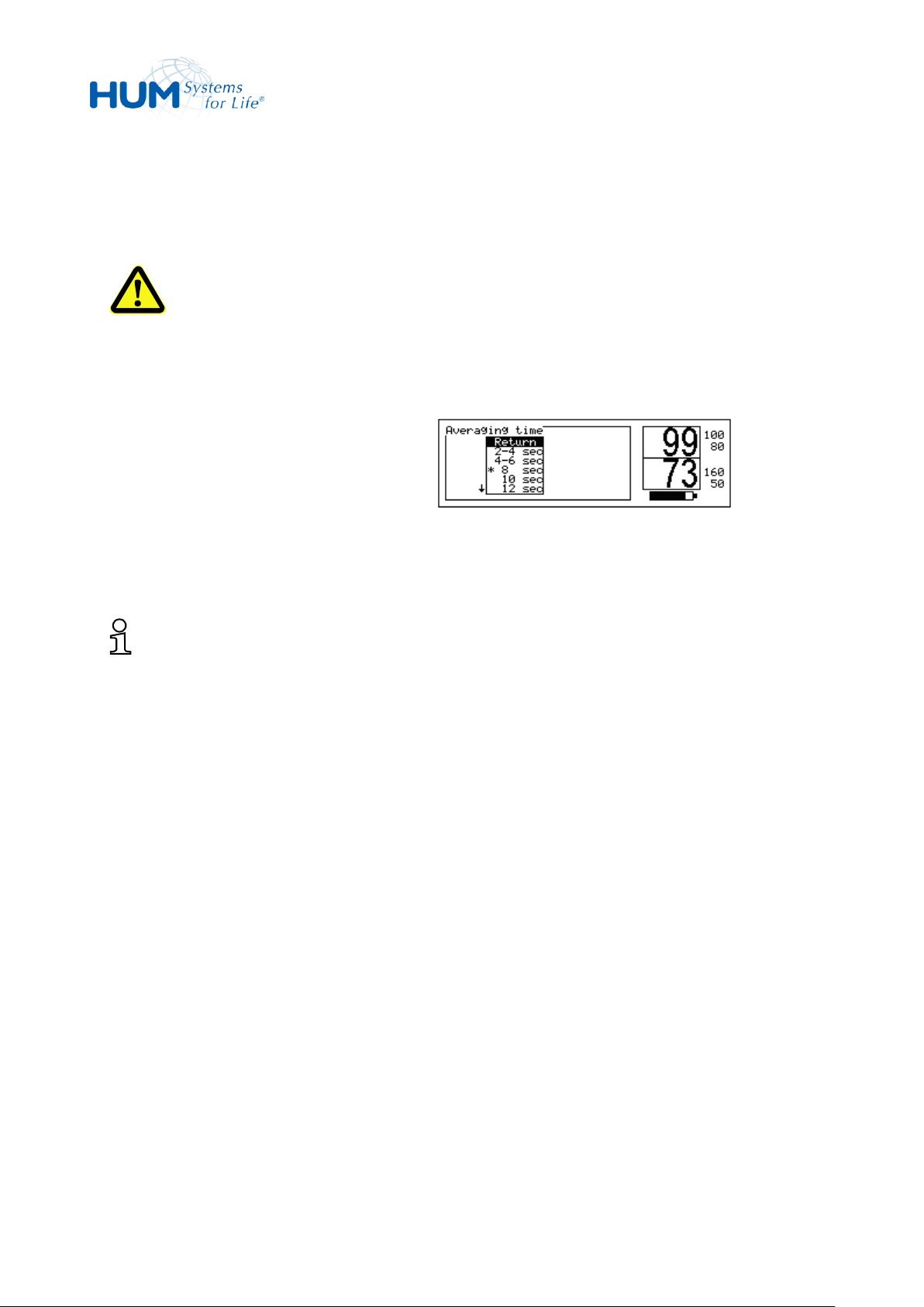
sat 805 Pulse Oximeter
Control
1. Starting from the main menu, call:
Configuration Signal
process Averaging time
2. Set the averaging time with the trim
knob between 2-4 and 16 sec.
3. Confirm this setting with Return.
Fig. 62: Averaging Time
The longer the length of time, in which measured values are collected, the lower the display value varies.
WARNING! Variations in oxygen saturation cannot be recognized!
Rapid changes in oxygen saturation are not recognized with the selection of a long averaging time!
What is FastSat™?
FastSat™ permits the display of sudden oxygen saturation changes. In general these rapid changes in
oxygen saturation are handled by the signal distribution i.e. display. FastSat™ can be especially
useful for incubations or for polysomnography, where a high level of reliability in the saturation
recognition process is desirable. FastSat™ is also able to stream the oxygen saturation changes from
breath to breath.
7.7.3.1 Perfusion Sensitivity (Algorithm mode)
The perfusion sensitivity can be set between Normal (“Norm.perfus.”), Maximum resp. high
(“Low. perfus.”) and APOD (“APOD”):
– The normal Perfusion –Sensitivity has been optimized for continuous long-term monitoring.
Depending on signal quality the lower signal strength value lies between 0.5% and 0.02%.
– The higher Perfusion –Sensitivity (= lower perfusion) may only be used for supervised clinical
situations. This setting is dependent on the sensor alarms, since it is only activated for signals
smaller than 0.02%. The lower signal strength value lies at 0.02%.
61
Page 62

sat 805 Pulse Oximeter
Control
1. Starting from the main menu, call:
Configuration Signal
process. Algorithm mode
2. Select the setting (Low. perfus.
/Norm.perfus./APOD) using the
trim knob.
3. Confirm this setting with Return.
Fig. 63: Perfusion Sensitivity
NOTICE!
If the signal deteriorates below the configured signal strength value, the unit turns to Pulse-SearchMode.
– APOD is a suite of complex and powerful signal processing algorithms that carefully analyze the
incoming signal to determine if the pulse oximeter sensor is ON or OFF the patient. Adaptive Probe
Off Detection (APOD) delivers enhanced protection against erroneous pulse rate and arterial oxygen
saturation readings when a sensor becomes detached from the patient. By providing another
sensitivity level, APOD directly addresses a problem common to pulse oximetry and gives the
clinician an unprecedented level of control.
APOD may be appropriate under conditions in which the Clinician/Patient ratio is lower than in the
intensive care unit and when contact between clinician and patient may be less continuous. It is
recommended for "step down" and "ward" care, and nursing home care situations. APOD is
appropriate where remote monitoring is employed. It is useful for patients that are at particular risk
of the sensor becoming detached (pediatric, combative, etc).
How does APOD compare to Max or Normal sensitivity?
APOD is the least sensitive in picking up a reading on patients with low perfusion. Normal Sensitivity
provides the best combination of sensitivity and probe-off detection performance and is
recommended for the majority of patients. Max Sensitivity is reserved for the sickest patients, where
obtaining a reading is most difficult. Max sensitivity is designed to interpret and display data for even
the weakest of signals, and is recommended during procedures and when clinician and patient
contact is continuous.
If low perfusion combined with movement inhibits the Masimo SET monitor from reading, switch from
APOD to Normal or Max sensitivity.
Three sensitivity levels enable the clinician to tailor the response of the sat 805 to the needs of the
particular patient situation - a truly unique and powerful capability.
62
Page 63

sat 805 Pulse Oximeter
Control
7.7.3.3 SmartTone (SmartTone)
The SmartTone is a feature that affects pulse beep and Signal IQ waveforms and can be selected as “ON” or
“OFF”.
When the SmartTone is ON, the Masimo SET algorithms will continue to provide pulse beep and Signal IQ
waveforms even when the pleth is noisy due to motion or low signal conditions.
With SmartTone OFF, the pulse beep and Signal IQ waveforms will suppress beep information during
periods of motion or low signal conditions.
The manufacturer’s preset for this parameter is „SmartTone ON“.
7.7.3.4 Artifact Filter (Artifact-Filter)
To eliminate short-term and therefore irrelevant losses of the pulse signal, an artifact filter can be applied
by selecting „ON“ or „OFF“.
This filter is applied to the following sensor-related alarms only:
No Sensor Connected,
Defective Sensor,
Interference Detected,
Sensor Off Patient,
Too Much Ambient Light,
Unrecognized Sensor
The artifact filter rejects sporadic alarm messages (of the same kind) up to a duration of 5 seconds. After
this period, the alarm will be triggered. In case the source for the alarm has vanished during the mute
period, no alarm is activated.
When activated, the symbol „AR“ is displayed in the lower right corner of the screen.
The manufacturer’s preset for this parameter is „Artifact filter OFF“ .
63
Page 64
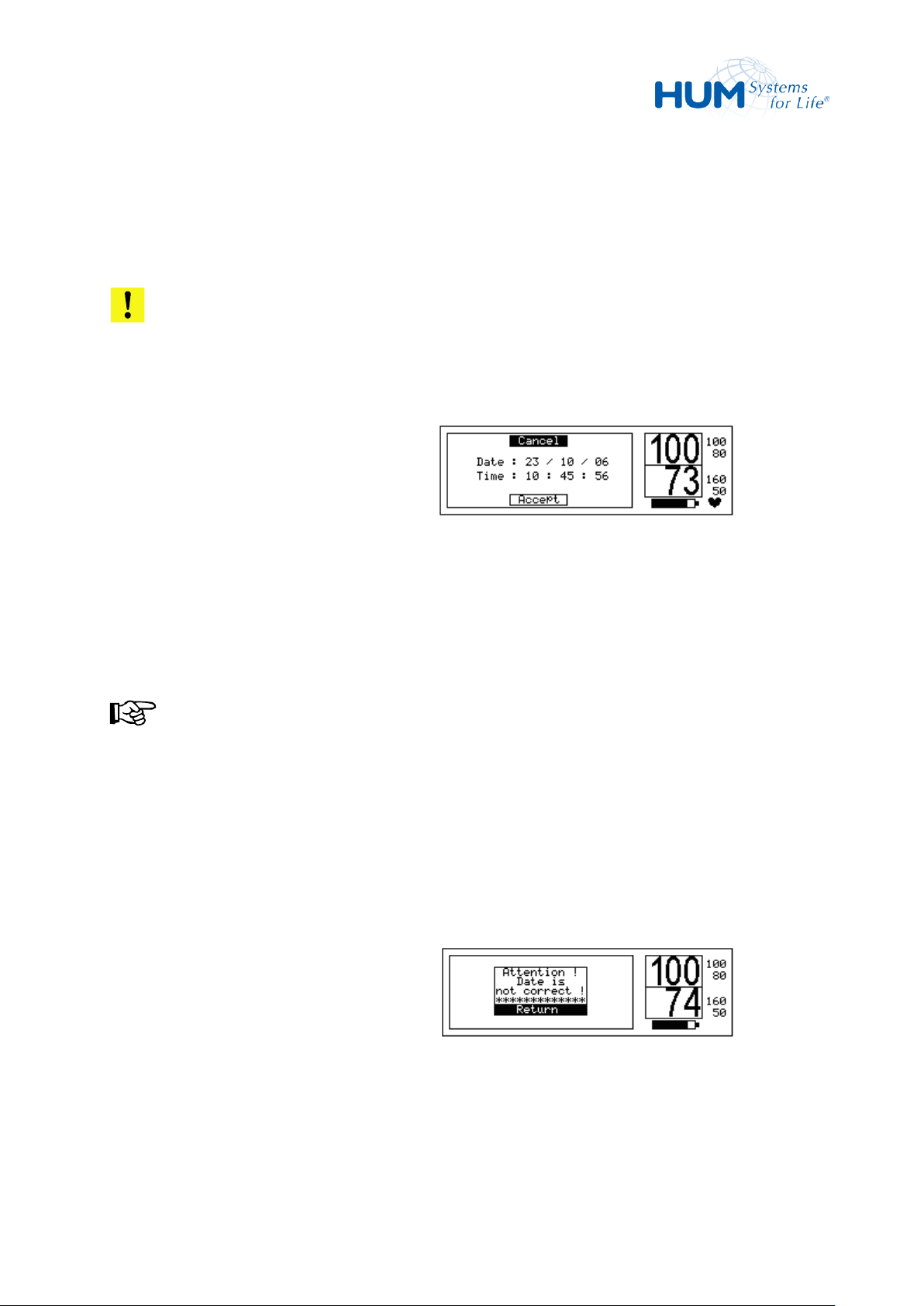
sat 805 Pulse Oximeter
Control
1. Starting from the main menu, call:
Configuration Clock
2. Select the first digit to be modified with
the trim knob.
3. Adjust the number with the trim knob.
4. Repeat this sequence for each number
to be modified.
5. Confirm this setting with Accept.
NOTICE!
The clock time does not run while
setting it. For that reason it makes sense
to set the clock time to a later point in
time, and then at precisely that point in
time press the trim knob to accept the
time and date.
Fig. 64: Setting the System Time
If you try to accept an invalid date (e.g.
30.02.07), the device responds with the
following message:
"Attention! Date is not
correct! ".
In that case no new date or time is set.
Fig. 65: Date is not correct
7.7.4 System Time (Clock)
The function sets the date and time of the unit. For a precise analysis of the stored monitoring data, it is
necessary to set the device time always correctly.
ATTENTION!
The user will need to adjust the time from summer to winter and vice versa manually!
64
Page 65
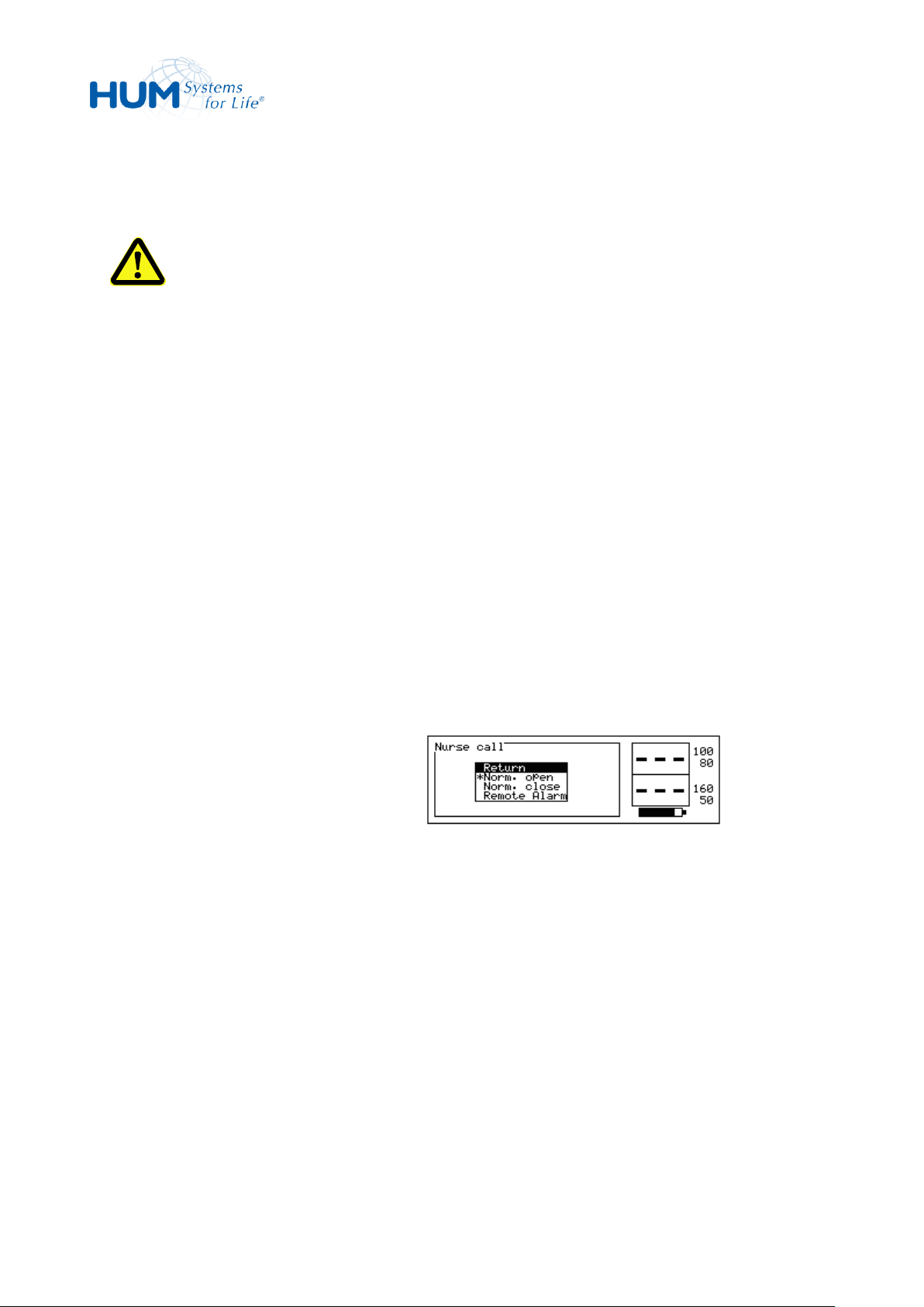
sat 805 Pulse Oximeter
Control
1. Starting from the main menu, call:
Configuration Nurse
call
2. Select the desired setting using the trim
knob (Norm.open / Norm.close /
Remote Alarm).
3. Confirm this setting with Return.
Fig. 66: Nurse call Interface Setting
7.7.5 External Alarm (Nurse Call)
WARNING! Danger by incorrect Configuration!
This setting is only allowed to be modified by experienced and training personal. A wrong setting
might de-activate the external alarm.
If the unit shall be connected via the external alarm interface, this interface can be set in accordance to the
respective system. For this, the relay contact can be configured as "Norm.(ally) open",
"Norm.(ally) closed" or "Remote Alarm".
– In the Norm. open setting the contact is permanently closed as long as the alarm condition
continues.
– In the Norm. close setting the contact is permanently open as long as the alarm condition
continues.
– Before connecting a remote alarm device, you must select the Remote alarm setting. This gives a
clocked transmission of coded alarm information from the device to the remote alarm device.
7.7.6 Device Information (Product Info)
By selecting menu ProductInfo you can call up the most important device settings on to the display:
– Device S/N and software version
– Version of the Masimo circuit board and its product identification
– DSP and microcontroller-versions
65
Page 66
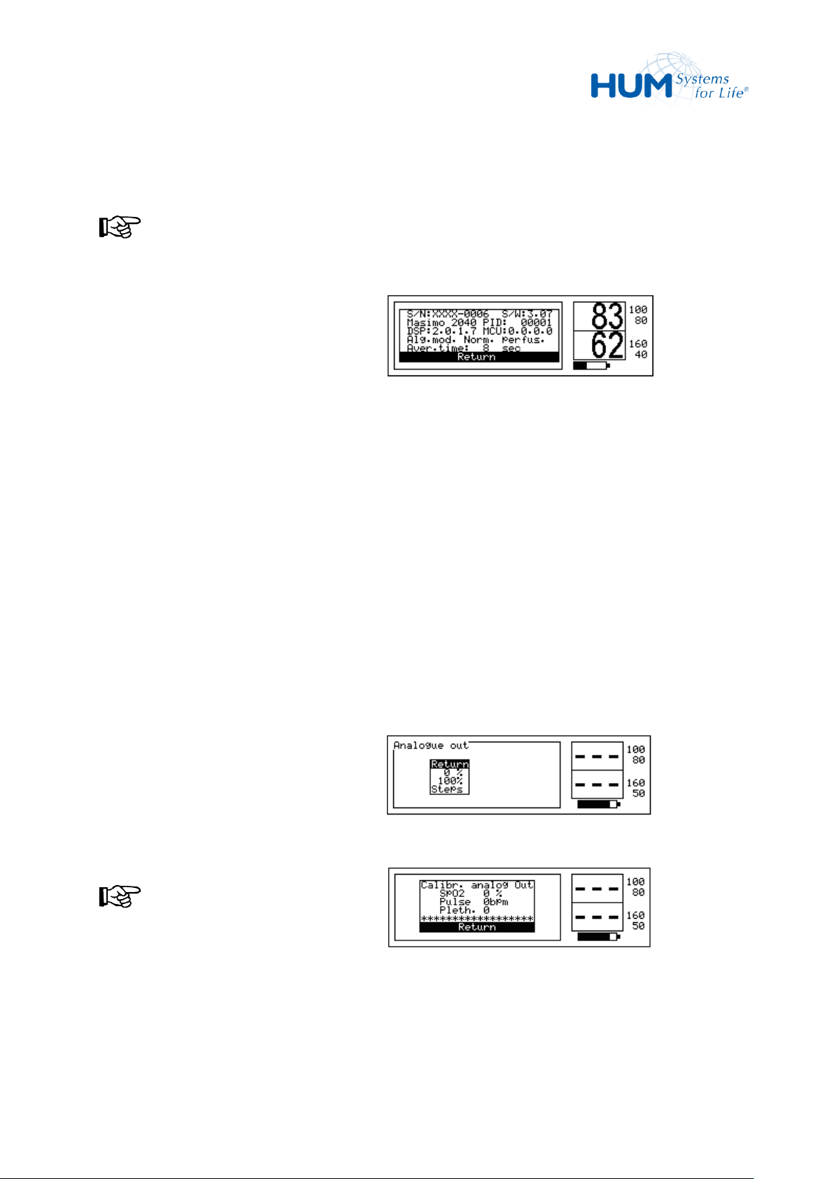
sat 805 Pulse Oximeter
Control
1. Starting from the main menu, call:
Product Info
2. Leave that window by confirming
Return.
Fig. 67: Device Information
1. Starting from the main menu, call:
Configuration Analogue
out
2. Select the desired function (0 % /
100 % / steps).
NOTICE!
The calibration signals are immediately
available on the interface.
3. Leave the menu by selecting Return.
Fig. 68: Analogue Interface
Fig. 69: Calibration
– Perfusion sensitivity setting
– Signal averaging time setting
NOTICE!
The displayed information is read-only.
7.7.7 Analogue Interface (Analogue out)
If required a calibration signal can be output at the analog interface.
For calibration, a null signal (0%), a full signal (100%) or a step function can be output.
– 0 %: On the interface, the analog voltages for 0% SpO2, 0 1/min pulse rate and the baseline for the
plethysmogram are output.
– 100 %: On the interface, the analog voltages for 100% SpO2, 240 1/min pulse rate and the full-scale
deflection of the plethysmogram are output.
– Steps: In this mode, voltage steps are output, starting at 0 volts and ending at 1.0 volt, rising by
incremental steps of 0.1 volt per second.
66
Page 67

sat 805 Pulse Oximeter
Control
7.8 Alarm lists (Alarm lists)
The sat 805 continuously stores monitoring data. SpO2, pulse and IQ values are continuously logged on a
second-by-second basis. In addition, data related to monitoring, such as alarms and device settings, are also
stored. In the basic extension stage, the device stores 160 hours of continuous monitoring with a maximum
of 4000 alarm list entries. Though only the last 500 are visible and displayed on the screen.
NOTICE!
Even in the case of an entire voltage loss the alarm lists remain unchanged.
Also in the state of ALARM VOLUME = 0 (=OFF) all alarms are logged.
On the device you have the option of analyzing the stored data in the form of lists and alarm event
graphics:
– a list of all alarm events
– the vital alarm list
– trend displays
The stored data can be exported via various interfaces for more detailed evaluation.
67
Page 68

sat 805 Pulse Oximeter
Control
1. Starting from the main menu, call:
Data Vital alarm list
The list of vital alarms is displayed.
From left to right, this shows:
– The serial alarm ID (e.g. no. 12),
– Date and time when the alarm
occurred (e.g. 23.10.06, 10:26h)
– The duration (e.g. 0 minutes 54
seconds)
– And the extreme value during the
alarm (e.g. 99 %)
2. Turn the encoder clockwise to browse
through the list.
Turn the encoder clockwise to show a
more recent alarm (i.e. higher alarm
numbers), turn the encoder counter
clockwise to show an older alarm (i.e.
lower alarm numbers).
3. Leave the list by confirming Return.
Fig. 70: Vital Alarm List
1. Starting from the main menu, call:
Data Total alarm list
The total list of vital alarms is displayed.
From left to right, this shows:
– The serial alarm ID (e.g. no. 15),
– Date and time when the alarm
Fig. 71: Total Alarm List
7.8.1 Vital Alarm List (Vital alarm list)
7.8.2 Total Alarm List (Total alarm list)
Selecting Total alarm list displays a list of all the alarm events (vital and technical alarms) as a table
on the display.
68
Page 69
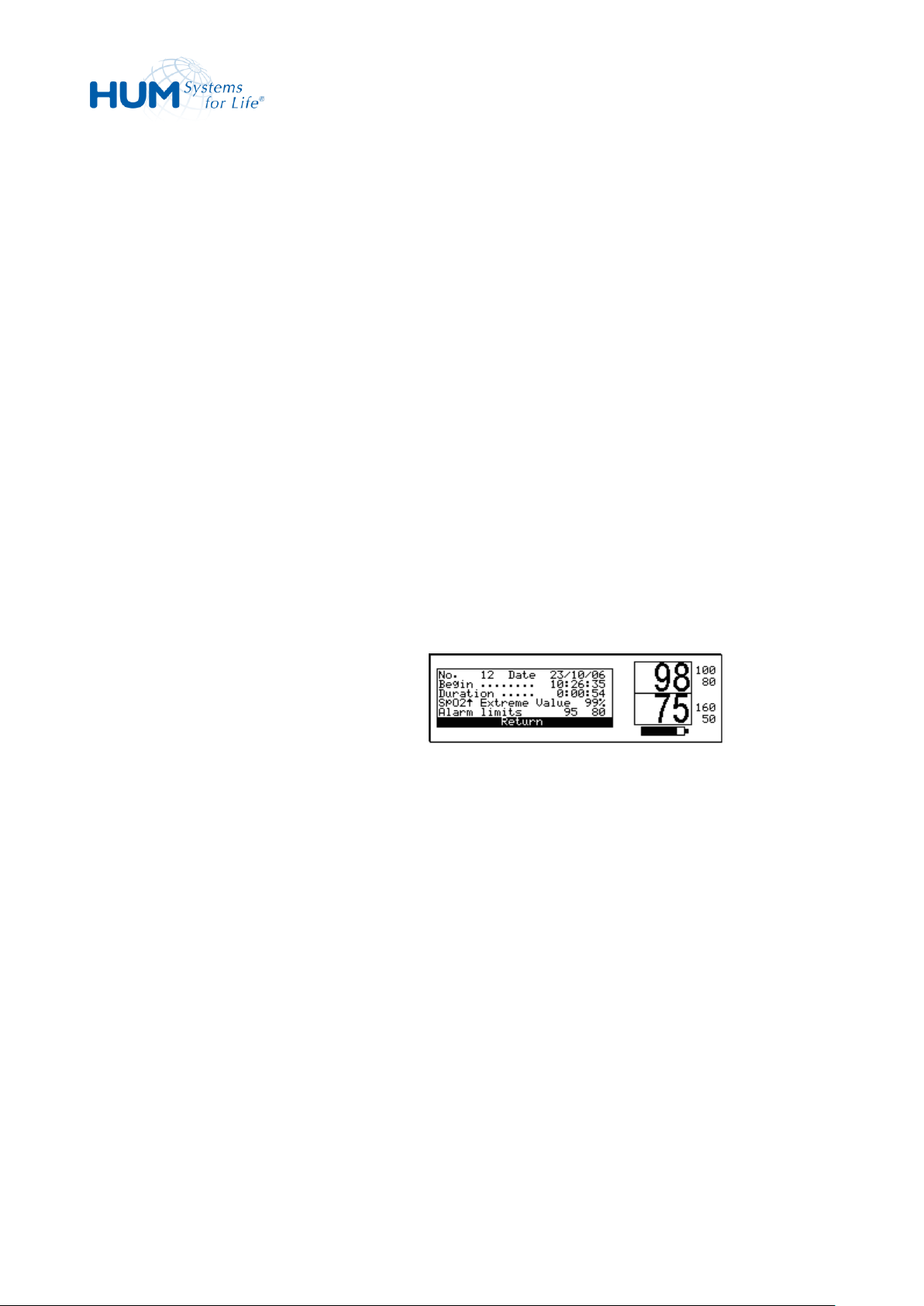
sat 805 Pulse Oximeter
Control
occurred (e.g. 23.10.06, 10:48h)
– The duration (e.g. 5 minutes 40
seconds)
– And the extreme value or type of alarm
event (e.g. Sensor failure)
2. Turn the encoder clockwise to browse
through the list.
Turn the encoder clockwise to show a more
recent alarm (i.e. higher alarm numbers),
turn the encoder counter clockwise to
show an older alarm (i.e. lower alarm
numbers).
3. Leave the list by confirming Return.
1. Call the Alarm list.
2. Mark an alarm entry and select it by
pressing the trim knob.
In the window, following information is
displayed:
– Start date
– Start time
– Alarm duration
– Type of alarm (here: SpO2 hi)
– Alarm limits
Extreme value or type of alarm
3. Leave the window by confirming
Return.
Fig. 72: Alarm Details
7.8.3 Alarm Details
69
Page 70
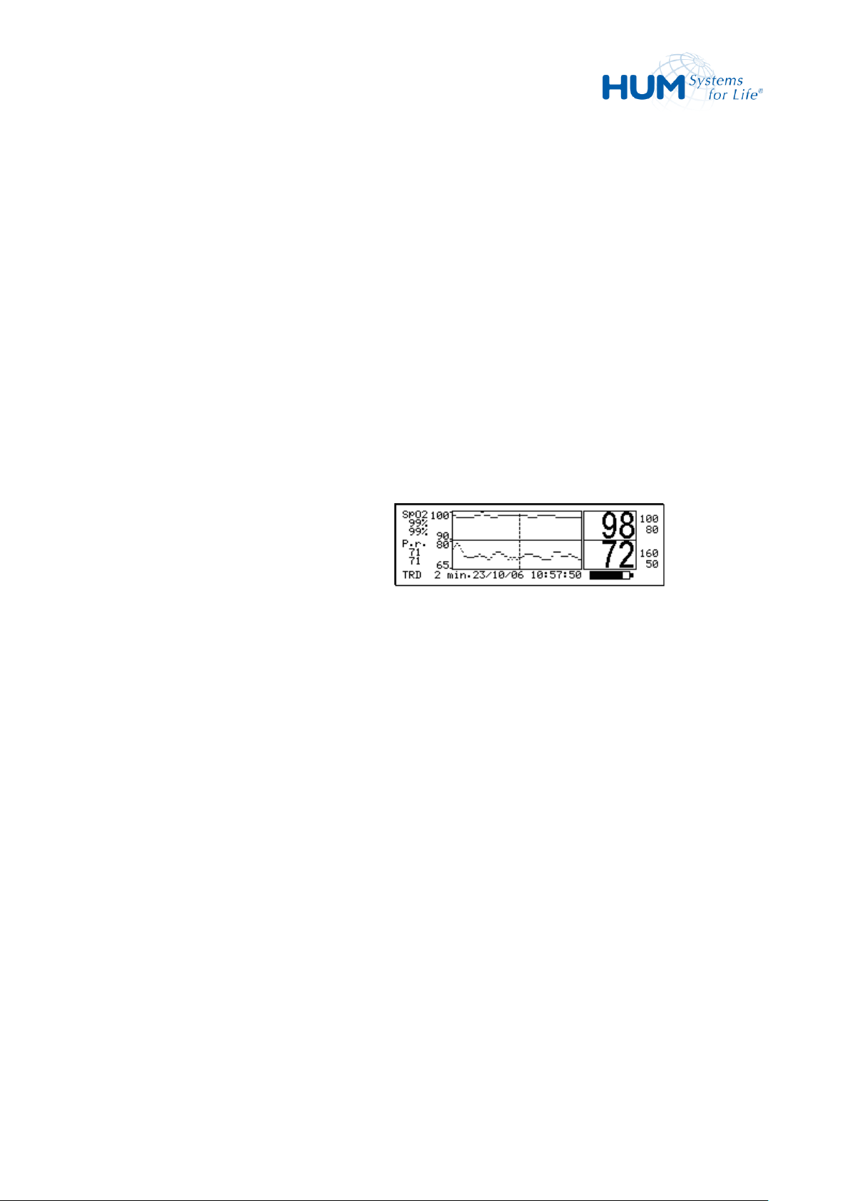
sat 805 Pulse Oximeter
Control
1. Starting from the main menu, call:
Data Trend
2. Select the time scale (2 minutes till
12 hours)
3. Select the display mode (SpO2, Pulse
or both).
The most recent data are displayed in
the required format.
4. Turn the trim knob clockwise to move
the pointer to later times and counter
clockwise to move to earlier times.
Fig. 73: Trend Display
7.9 Trend Display (Trend)
The sat 805 continuously stores monitoring data. The SpO2, pulse and IQ values are recorded every second.
In addition, it also stores monitoring-related data such as alarms and device settings.
The basic sat 805 model stores up to 160 hours of continuous monitoring with a maximum of 4,000 alarm
list entries.
The sat 805 offers an easy and quick graphical trend display on the device.
The device records the oxygen saturation and pulse rate data every second continuously. In the Trend
display, this can be shown as a trace (SpO2 or pulse) or both simultaneously over different time as (12, 8, 6,
4, 2 hours; 60, 30, 10, 4, 2 minutes).
7.9.1 Trend Display
At the current position (the position of the screen marker) are displayed:
Left:
– Minimum (lower value) and maximum (upper value) at that point in time. "---" is displayed if
Lower Line
70
there are no values available.
– Selected display mode
– Time scale (2 minutes till 12 hours)
– Date (here: 23.10.06) and time (here: 10:57.50)
Page 71
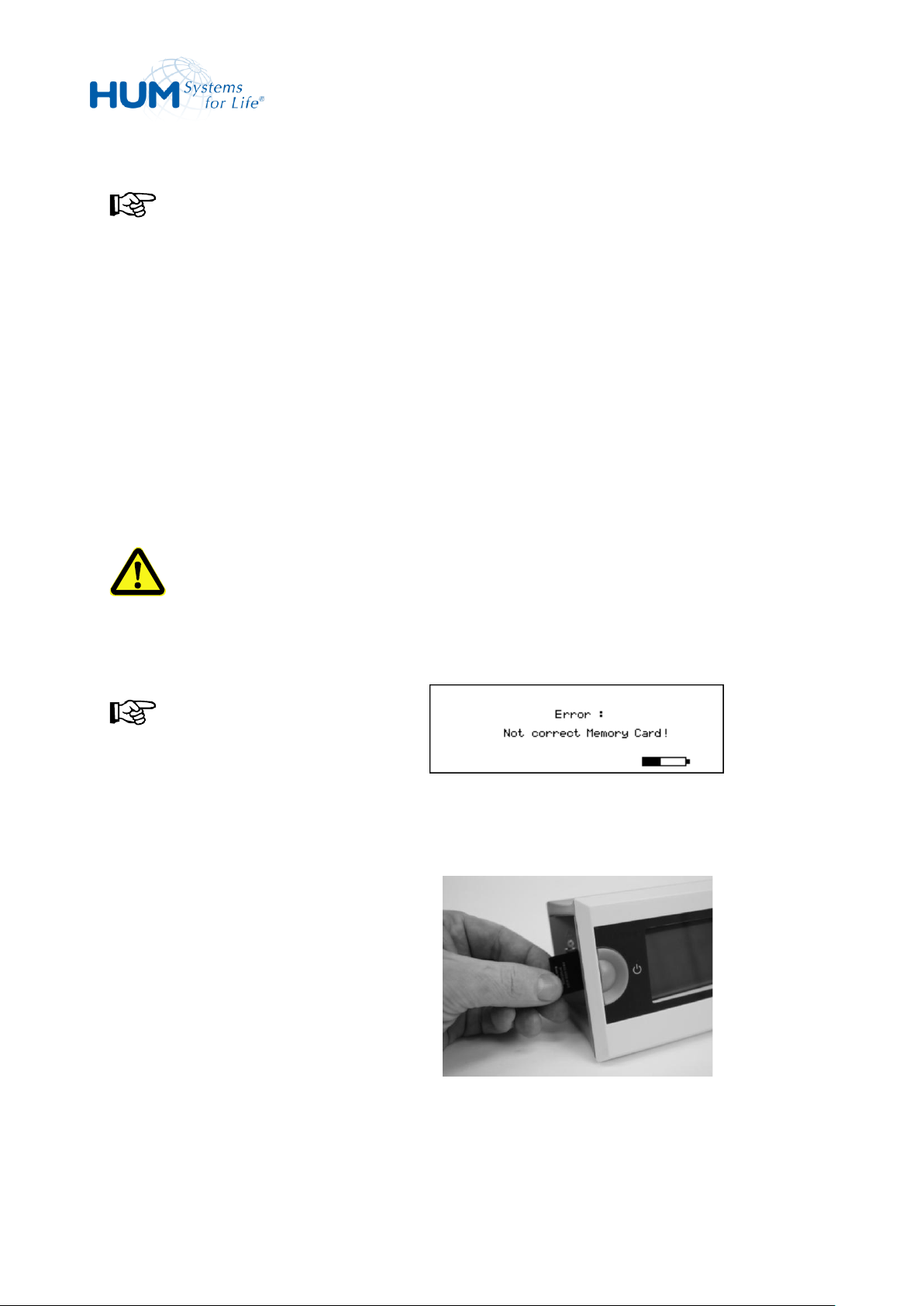
sat 805 Pulse Oximeter
Control
NOTICE!
The pulse oximeter only accepts empty
(erased) SD cards. All other cards will be
refused, with an error message.
Fig. 74: Card not readable
1. Switch off the device.
2. With the angled edge to the top and the
exposed contacts facing forwards, insert
the empty SD card into the slot until it is
firmly in place.
Fig. 75: Inserting SD Card
NOTICE!
When the marker reaches the left or right hand edge of the display, the area shown is moved by half
a screen to one side.
The screen marker cannot move beyond the start or the end of the data.
5. For leaving the trend display, press the trim knob.
7.10 Exporting the Data
For further analysis, the stored data can be exported to a SD card.
WARNING!
Whilst the data is being exported, there is no monitoring and therefore no alarms should the
patient be in a life-threatening situation!
.
71
Page 72
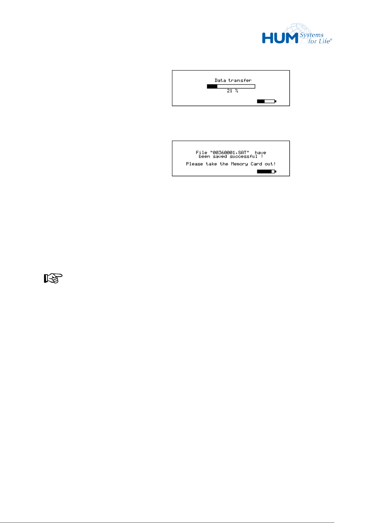
sat 805 Pulse Oximeter
Control
3. Switch on the device.
It automatically detects the SD card and
goes into data transmission mode.
After a short while the data transfer is
complete – for the complete file about
20 seconds are needed.
Fig. 76: Transmitting Data
When transmission is complete, the
message:
"File … has been saved
successful !
Please take the Memory Card
out!"
is displayed.
When the data has been successfully
written to the SD card, the data memory
in the device is automatically deleted.
NOTICE!
If the transmission is interrupted or a
fault occurs, the pulse oximeter outputs
an error message. No data is stored on
the SD card in this event.
4. Take the SD card out.
The data on the SD card can then be
processed with a graphics and analysis
program, for example "satView".
Fig. 77: Remove SD Card
72
Page 73

sat 805 Pulse Oximeter
Alarms
8 Alarms
8.1 General
As a monitoring system, the sat 805 pulse oximeter is equipped with acoustic and visual signals for many
alarm situations. It alerts the user:
– When deviations from pre-set alarm limits occur
– In problem situations during technical monitoring
– Internal unit malfunctions
WARNING! Danger by incorrectly entered Alarm Limits!
Always check the alarm limits each time before using the pulse oximeter, in order to ensure that
the current limits are appropriate for the patient in question.
If there is any doubt as to the accuracy of the values shown, first check the patient's vital
parameters using other methods and then investigate whether the device is functioning.
WARNING! Danger by quiet alarm tones!
Please ensure that the openings of the loudspeaker are not covered in any way.
Inaccurate measurements can be caused by:
– Incorrect sensor connection or incorrectly selected Masimo-sensor.
– A significant proportion of dysfunctional hemoglobin (e.g. carboxyhemoglobin or methemoglobin).
– Intravascular dyes such as indocyanine green or methylene blue are present in the blood stream.
– Excessive light intrusion, such as operating lamps (especially xenon light sources), bilirubin lamps,
fluorescent lights, infrared heat sources or direct sun light (excessive light intrusion can be avoided
with a dark or transparent sensor shade).
– Excessive movement of the patient.
– Venous blood pulses.
73
Page 74

sat 805 Pulse Oximeter
Alarms
– Attaching the sensor to a limb at the same time as a blood pressure cuff, an arterial catheter or an
intravascular line.
Loss of pulse signal might occur under the following conditions:
– The sensor is attached too tightly.
– There is too much light from operating theatre lights, bilirubin lamps or sunlight.
– An inflated blood pressure cuff is attached to the same extremity as the sensor.
– The patient suffers from low blood pressure, severe vasoconstriction and/or anaemia or
hypothermia.
– The artery is obstructed close to the sensor.
– The patient is in shock or cardiac arrest.
– The fingernail is varnished.
8.2 Alarm Categories
There are three alarm categories:
– High priority alarms
require immediate user intervention in order to avoid possible damage to the patient.
– Medium priority alarms
show a technical problem and require immediate user intervention.
– Low priority alarms
require elevated attention by the user.
8.2.1 High Priority Alarms
High priority alarms require immediate action by the user in order to avert any possible harm to the
patient.
74
Page 75
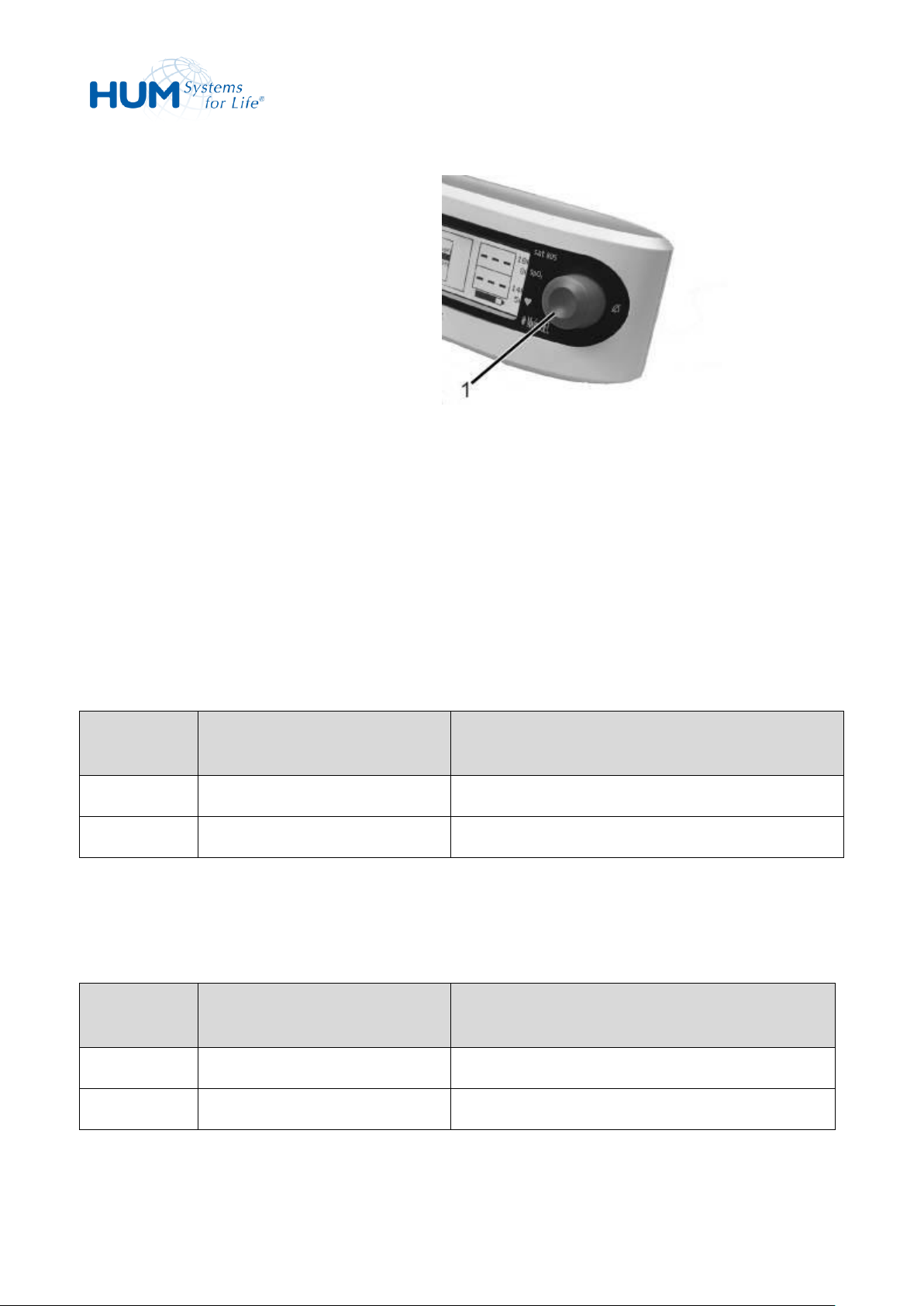
sat 805 Pulse Oximeter
Alarms
With high priority alarms
– the high-priority alarm tone sounds,
– the red alarm-LEDs (1) flash and
– a status line message appears.
These signals remain active for as long as the
condition causing the alarm persists.
If the condition causing the alarm is no longer
present, then the signal goes off.
Every alarm results in an entry in the alarm list
as well as the storage of the graphic alarm
events.
Fig. 78: Alarm LEDs
Status Line
Message
Message in the LC Display
Cause
SpO2
flashing SpO2 values
Oxygen saturation exceeds the set alarm limit.
SpO2
flashing SpO2 value
Oxygen saturation falls below the set alarm limit.
Status Line
Message
Message in the LC Display
Cause
P.r.
flashing pulse rate value
Pulse rate exceeds the set alarm limit.
P.r.
flashing pulse rate value
Pulse rate falls below the set alarm limit.
If the trim knob is pressed during an acoustic alarm signal, then the signal tone is suppressed for the
duration of the pre-set acoustic alarm suppression time.
If the setting “Acoustic alarm OFF” has been selected in the configuration menu, then an alarm does not
sound. Only the visual signals can notify the responsible user of the presence of an alarm condition.
8.2.1.1 SpO
Alarm
2
The elapsed duration and the extreme value of the current alarm is displayed on the status line.
8.2.1.2 Pulse Rate Alarm
The elapsed duration and the extreme value of the current alarm is displayed on the status line.
75
Page 76

sat 805 Pulse Oximeter
Alarms
Status Line Message
Description
Solution
No sensor
connected!
The sensor is not or incorrectly connected to the
unit.
Check connection between
patient cable and sensor. If
needed, replace sensor.
No adh. sensor
connected!(*)
The sensor is not or incorrectly connected to the
unit.
Check connection between
patient cable and sensor. If
needed, replace sensor.
No cable
connected! (*)
The patient cable is not or incorrectly connected
to the unit.
Check patient cable
connection between unit
and sensor. If needed,
replace the patient cable.
Sensor off
patient!
The sensor is connected to the unit, the unit is
on, but no patient can be recognized.
Position the sensor
correctly.
Defective
sensor!
The device has determined that the sensor does
not function at all or only to a limited extent.
Replace the sensor with a
new Masimo sensor!
Unrecognized
sensor!
The device has detected a sensor that is not
approved for this system
or the lifetime has been exceeded.
Only connect Masimo
sensors
or connect a new sensor!
"Defective adh.
sensor!" (*)
The device has determined that the sensor does
not function at all or only to a limited extent.
Replace the sensor with a
new Masimo sensor!
"Defective
cable!" (*)
The device has determined that the patient
cable does not function at all or only to a limited
extent.
Replace the sensor with a
new Masimo patient cable!
8.2.1.3 Sensor Alarms
NOTICE!
X-CAL or lifetime related alarms (*) might not be present in all devices.
To confirm, please check in the product info menu (see chapter 7.7.6): only devices with DSP version
5.X.X.X will support the X-CAL related alarms and messages.
76
Page 77

sat 805 Pulse Oximeter
Alarms
Status Line Message
Description
Solution
„Incompatible
sensor!“ (*)
The device has detected a sensor that is not
approved for this system.
Only connect approved
Masimo sensors to the unit.
„Incompatible
adh. sensor!“
(*)
The device has detected a sensor that is not
approved for this system.
Only connect approved
Masimo sensors to the unit.
„Unrecognized
adh. sensor!“
(*)
The device has detected a sensor that is not
approved for this system.
Only connect approved
Masimo sensors to the unit.
„Check cable &
sensor!“ (*)
The system has detected a possible fault in the
accessories or
following a (no data) alarm after the next 120
seconds this alarm is triggered.
Check cable and sensor,
replace if necessary or
Clean the sensor
Reposition the sensor
Exchange the sensor
or/and patient cable with
a new one!
„Check sensor“
(*)
The system has detected a possible fault in the
accessories.
Check cable and sensor,
replace if necessary
8.2.1.4 System Alarms
WARNING! No Monitoring with System Alarm!
The monitoring function is turned off by system alarm. For the duration of the system alarm the
patient is not correctly monitored. The patient must be monitored by other means.
A system alarm indicates that reliable monitoring is no longer being performed due to a technical
error. The unit can and may no longer be used when this alarm occurs.
77
Page 78
sat 805 Pulse Oximeter
Alarms
Message
Source
SYST ALARM: bat low!
The battery voltage is below a level that guarantees
reliable operation.
SYST ALARM: MS-FIFO!
An error has arisen in the Masimo input data memory.
SYST ALARM: MS-timeout!
The Masimo-circuit board has not responded to
several queries or does not provide data for more
than 60 seconds.
SYST ALARM: MS-comm.!
The Masimo-data transfer has a permanent defect.
SYST ALARM: MS-error!
The Masimo circuit board has reported an irreparable
defect.
SYST ALARM: Unexp.reset!
An unexpected device restart has occurred.
SYST ALARM: NVRAM error!
The internal non-volatile memory has reported an
error.
SYST ALARM: WDT error!
The integrated circuit that monitors the sat 805 has
reported an error.
SYST ALARM: Reset monitor
The integrated circuit that monitors the sat 805 has
Action for System Alarm Occurrence:
1. Secure monitoring of patient by other means.
2. Turn off unit by pressing the ON/OFF button.
3. Turn the unit back ON.
If the self-test occurs without errors, the unit can be used again for monitoring.
If an error occurs during the self-test, turn the unit OFF and take to a medical supplier for repairs.
WARNING! Danger to the Patient!
Never use a unit that indicates a system alarm.
System Alarm Messages:
78
Page 79
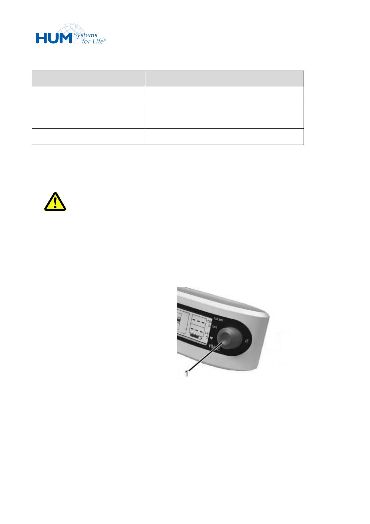
sat 805 Pulse Oximeter
Alarms
Message
Source
reported an error.
SYST ALARM: Stack overfl.
An error has occurred in the software stack
processing.
SYST ALARM: ROM-CRC!
A data security error has occurred.
With medium-priority alarms,
– the medium-priority alarm tone sounds,
– the yellow alarm-LEDs (1) flash and
– a status line message appears.
Fig. 79: Alarm LEDs
8.2.2 Medium Priority Alarms
WARNING! Insufficient Monitoring at Medium Priority Alarms.
With alarms of mid-level priority a correct signal reception cannot be guaranteed. At times the
patient will not be monitored correctly for the duration of the alarm. The cause of the alarm must
be corrected as soon as possible.
Medium priority alarms display technical problems and require quick user intervention.
79
Page 80
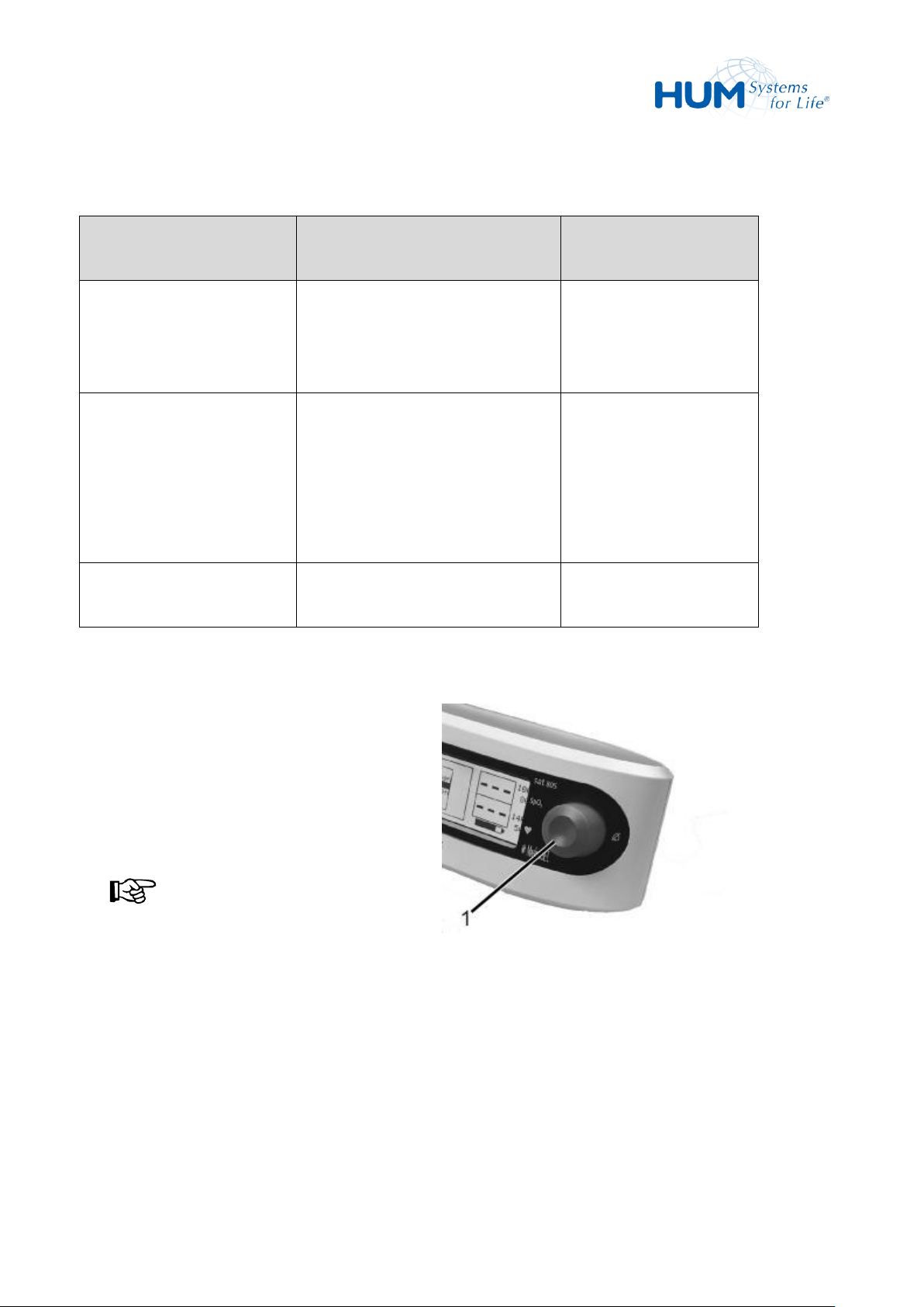
sat 805 Pulse Oximeter
Alarms
Status Line
Message
Description
Solution
MS-Comm. lost
data!
Data transfer error. The device has
registered this fact and has
automatically restored
communication.
No user intervention
required.
No data!
The unit has determined the
sensor or patient cable does not
work properly.
After 60 seconds a system alarm is
triggered.
Clean the sensor
Reposition the sensor
Exchange the sensor
or/and patient cable
with a new one!
Battery depleted!
Remaining operation time of 15
minutes or less
Recharge battery
With a low priority alarm
– the audio sound of low priority is heard,
– the yellow alarm LEDs (1) light and
– the status line message appears.
NOTICE!
With low priority alarms, the LEDs (1) do
NOT blink.
Fig. 80: No Alarm-LED
Medium Priority Alarms:
8.2.3 Low Priority Alarms
Low Priority Alarms require additional attentiveness by the user.
80
Page 81

sat 805 Pulse Oximeter
Alarms
Status Line Message
Description
Solution
Mains power supply!
The mains power or the
DC power supply is
interrupted/defect.
Check the mains power (fuses) and
also the DC power pack. Is the green
LED glowing?
Loudspeaker defective!
The sat 805 has detected a
defective alarm
loudspeaker and has
switched over to the
internal substitute signal
device.
A defective loudspeaker can only be
replaced by qualified personnel. Notify
your medical technology dealer.
Status Line Message
Description
Solution
Low perfusion!
The unit has determined
insufficient circulation for reliable
determination of oxygen saturation
values.
Remove the sensor and position
at a different place.
Signal IQ too low!
The signal strength for signal
reliability is too low.
Remove the sensor and position
at a different place.
Pulse search!
At too low perfusion or during the
initialization, the device attempts
to synchronize with the detected
perfusion.
If the device will remain in this
state after switching on or this
message is displayed during the
operation, remove the sensor and
position at a different place.
Interference!
The unit has determined influence
from a second light source or a
second sensor.
Remove the interfering source.
Only use a new Masimo sensor.
Low Priority Alarms:
8.3 Status message
The following status messages provide information about the actual monitoring situation:
81
Page 82

sat 805 Pulse Oximeter
Alarms
Status Line Message
Description
Solution
Ambient Light!
The unit has determined a
scattered or foreign light source.
This can occur with particularly
strong lighting from the outside
(especially from xenon or similar
lamps).
Do not expose the sensor to a
direct light source, or shade from
the outside.
Status messages are not alarms and there not accompanied by LED activation.
Status messages may be mask with higher ranking alarms.
8.4 Battery Alarms
The device warns the user in good time of low or insufficient battery capacity, and reminds the user in good
time to connect the pulse oximeter again to the mains supply and to recharge the internal battery.
There are three stages in battery alarm management:
– Battery alarm low priority
– Battery alarm medium priority
– System battery alarm (high priority)
WARNING! Insufficient Monitoring!
With continued battery alarm act quickly. Monitoring of the patient can discontinue in a short
time.
Reconnect to the device to mains and recharge the unit.
Once connected to the mains power supply, the battery alarm will be automatically reset.
However if the recharging is interrupted early, and the device is again run but not off the mains, the battery
alarm may immediately be triggered again.
82
Page 83

sat 805 Pulse Oximeter
Alarms
Status Line Message
Description
Solution
Battery low!
Remaining operation time of
one hour or less.
Recharge battery.
Status Line Message
Description
Solution
Battery depleted!
Remaining operation time of
15 minutes or less.
Recharge battery.
Status Line Message
Description
Solution
SYST ALARM: Bat
low!
Battery capacity is so low,
that reliable monitoring can
no longer be guaranteed.
Signal processing and the
monitoring function are
disabled.
Recharge battery.
8.4.1 Battery Alarm (low priority)
A flashing battery icon will be displayed.
8.4.2 Battery Alarm (medium priority)
A flashing battery icon will be displayed.
8.4.3 Battery Alarm (high priority)
An empty battery icon will be displayed.
8.5 Combination of Alarms of Different Priorities
With overlapping different alarm conditions the latest alarm with the highest priority is activated.
With concurrently occurring alarms the highest ranking is activated. If these alarm conditions are removed,
the next lower waiting alarm is immediately displayed.
A new alarm condition of higher priority immediately supersedes any lower ranking alarm.
83
Page 84
sat 805 Pulse Oximeter
Malfunctions and Troubleshooting
Message
Cause
Solution
Unit cannot be turned on.
Batteries are empty.
Recharge batteries: connect unit
to electricity.
Should function not occur even
with a networked connection,
inform medical device supplier.
The information displayed on the
LCD is difficult to read.
The display contrast is set
incorrectly.
Set the display contrast that the
information is easy to read.
When in use buttons do not work.
Internal failure.
Inform medical device supplier.
9 Malfunctions and Troubleshooting
WARNING! Insufficient Monitoring by Malfunctions!
With the occurrence of function failure the patient cannot be correctly monitored in certain cases.
The cause of the function failure must be removed as soon as possible.
Immediately assure monitoring of patient by other means.
Action at Function Failure:
1. Secure monitoring of patient by other means.
2. Remove unit from patient.
3. Remove external interfaces.
4. Correct failure with help of Table below.
WARNING! Danger to the Patient!
Never use a malfunctioning unit.
List of possible Malfunctions / Error Messages:
84
Page 85

sat 805 Pulse Oximeter
Malfunctions and Troubleshooting
Message
Cause
Solution
Error message after self-test run
and after unit is turned on.
Internal failure.
Turn the unit ON and OFF.
Inform medical device supplier.
No function of the alarm loud
speaker. Internal substitute buzzer
sounds.
Defective alarm loudspeaker.
Inform medical device supplier.
Status Line Message:
“Sensor not connected!“
The patient cable is not or
incorrectly connected to the unit.
The connection between sensor
input and patient cable is
interrupted.
Check connection between unit
and sensor. If needed, replace
sensor or patient cable.
Status Line Message:
“Sensor defect! “
The unit has determined the
sensor does not work or only in
limited capacity.
Exchange the sensor with a
Masimo-Sensor!
Status Line Message:
"Defective adh.
sensor!"
The device has determined that
the sensor does not function at
all or only to a limited extent.
Replace the sensor with a new
one!
Status Line Message:
"Defective patient
cable!"
The device has determined that
the patient cable does not
function at all or only to a limited
extent.
Replace the patient cable with a
new one!
Status Line Message:
“Low perfusion! “
The unit has determined
insufficient circulation for
reliable determination of oxygen
saturation values.
Remove the sensor and connect
at a different place.
Status Line Message:
“Interference! “
The unit has determined
influence from a second light
source or a second sensor.
Do not expose the sensor to a
direct light source.
Only use a new Masimo-Sensor.
85
Page 86

sat 805 Pulse Oximeter
Malfunctions and Troubleshooting
Message
Cause
Solution
Status Line Message:
“Pulse search! “
With too low perfusion or whilst
the initialisation the unit tries to
synchronize with the defect
perfusion.
If the unit remains in this
situation after turning on or if the
alarm is activated while
operating, remove the sensor and
position at a different place.
Status Line Message:
“Sensor not on Patient!
“
The sensor is connected to the
unit, the unit is on, but no
patient can be recognized.
Position the sensor correctly.
Status Line Message:
“Ambient Light! “
The unit has determined a
scattered or foreign light source.
This can occur with particularly
strong lighting from the outside
(especially from xenon or similar
lamps).
Do not expose the sensor to a
direct light source, or shade from
the outside.
Status Line Message:
“Signal IQ too low! “
The signal strength for signal
reliability is too low.
Remove the sensor and position
at a different place.
Status Line Message:
“MS-Comm. lost data! “
Data transfer error. The device
has registered this fact and has
automatically restored
communication.
No user intervention required.
Status Line Message:
“Unrecognized Sensor!“
The unit has discovered a sensor
not approved for this system.
Only use authorized Masimo
accessories.
Status Line Message:
"Patient cable near
expiration!"
The patient cable has reached
90% of its specified life time.
Have a new patient cable ready.
Status Line Message:
"Sensor near
expiration!"
The sensor has reached 90% of
its specified life time.
Have a new sensor ready.
86
Page 87

sat 805 Pulse Oximeter
Malfunctions and Troubleshooting
Message
Cause
Solution
Status Line Message:
"Adh. Sensor near
expiration!"
The adhesive sensor has reached
90% of its specified life time.
Have a new sensor ready.
Status Line Message:
"X-CAL: Patient cable
expired!"
The patient cable has reached
100% of its specified life time.
Replace patient cable.
Status Line Message:
"XCAL:Sensor expired!"
The sensor has reached 100% of
its specified life time.
Replace sensor.
Status Line Message:
"X-CAL:Adh. sensor
expired
The sensor has reached 100% of
its specified life time.
Replace sensor.
Status Line Message:
"Check sensor
connection!"
The system has detected a
possible fault in the accessories.
Check connection between
patient cable and sensor. If
needed, replace sensor and/or
cable.
Status Line Message:
"Check cable and
sensor!"
The system has detected a
possible fault in the accessories.
Check connection between
patient cable and sensor. If
needed, replace sensor and/or
cable.
Status Line Message:
„No adh. sensor
connected“
The sensor is not or incorrectly
connected to the unit.
Check sensor. If needed, replace
sensor.
Status Line Message:
„No patient cable
connected“
The patient cable is not or
incorrectly connected to the unit.
Check patient cable. If needed,
replace cable.
Status Line Message:
„Unrecognized cable“
The unit has discovered a patient
cable not approved for this
system.
Use approved Masimo
accessories only.
87
Page 88

sat 805 Pulse Oximeter
Malfunctions and Troubleshooting
Message
Cause
Solution
Status Line Message:
“Unrecognized adh.
sensor!“
The unit has discovered a sensor
not approved for this system.
Use approved Masimo
accessories only.
Status Line Message:
„Incompatible sensor“
The unit has discovered a sensor
not approved for this system
Use approved Masimo
accessories only.
Status Line Message:
„Incompatible cable“
The unit has discovered a patient
cable not approved for this
system.
Use approved Masimo
accessories only.
88
Page 89

sat 805 Pulse Oximeter
Disinfecting, Cleaning and Maintenance
Interval
Сleaning
Daily
(In the clinic)
Clean and disinfect reusable sensors
Every 14 days
Clean and disinfect patient cable
Every 14 days
(In the clinic)
Dispose of disposable sensors
Weekly
(In the clinic)
Clean and disinfect sat 805 & patient cable
Weekly
(outside of the hospital)
Clean sat 805
Every 4 Weeks
(outside of the hospital)
Dispose of disposable sensors
At change of patient
Clean and disinfect sat 805 included carrying bag, AC adapter,
patient cable and reusable sensors
At change of patient
Dispose of disposable sensors
After service activities
Clean and disinfect sat 805 included carrying bag, AC adapter,
patient cable and reusable sensors
After service activities
Dispose of disposable sensors
10 Disinfecting, Cleaning and Maintenance
The natural aging and abrasion of certain assemblies of the unit require regular cleansing and maintenance.
10.1 Cleaning Plan
89
Page 90

sat 805 Pulse Oximeter
Disinfecting, Cleaning and Maintenance
10.2 Disinfection
It has been proven, wipe disinfection is more thorough and comprehensive than spray disinfection. We
recommend to use Meliseptol rapid (manufacturer B.Braun) in the same manner like for the above outlined
cleaning procedure.
10.2.1 Disinfecting the Unit
ATTENTION! Danger to the Unit!
Do not use disinfectants other than those authorised. Proceed particularly cautiously in the LCD
display area to avoid scratching the surface. Never immerse the unit in or under water i.e. into
another liquid. The unit as well as the applicable Masimo accessories do not sustain autoclave,
steam or gas sterilization.
1. Switch off the unit before cleaning and disconnect the mains and patient connections.
2. The application instructions of the disinfectant manufacturer must be followed. Disinfection takes
place as part of a surface wipe disinfection. For this purpose, the disinfectant is distributed on a
disposable wipe and the surface of the pulse oximeter to be disinfected is wiped off using the cross
method (2 x longitudinal/2 x transverse). After the manufacturer- and disinfectant-dependent
exposure time, further use can be made.
3. Allow the device to dry completely before the next use.
10.2.2 Disinfecting the Masimo sensors
NOTICE!
The single patient sensors (adhesive sensors) are only intended for use on one patient and must not
be cleaned or reused.
ATTENTION: Danger to sensor functionality!
Do not use undiluted bleach 15% - 5.25% sodium hypochlorite or any cleaning solution other than
those recommended here because permanent damage to the sensor may occur.
Do not immerse the sensor or connector in any liquid solution.
Do not sterilize by irradiation, steam autoclave or ethylene oxide!
90
Page 91

sat 805 Pulse Oximeter
Disinfecting, Cleaning and Maintenance
Disinfect the reusable Masimo sensors as follows:
1. Disconnect the connection from both the patient and the patient cable.
2. For disinfection, use a 1:10 bleach /water solution.
3. Saturate a cloth or gauze pad with the cleaning solution und wipe all surfaces of the sensor and
cable.
4. Saturate another cloth or gauze pad with sterile or distilled water and wipe all surfaces of the sensor
and cable.
5. Dry the sensor with a clean cloth or dry gauze pad.
10.2.3 Disinfecting the patient cable
ATTENTION: Danger to cable functionality!
Do not use undiluted bleach 15% - 5.25% sodium hypochlorite or any cleaning solution other than
those recommended here because permanent damage to the sensor may occur.
Do not immerse the cable or connector in any liquid solution.
Do not sterilize by irradiation, steam autoclave or ethylene oxide!
Disinfect the patient cable as follows:
1. Disconnect the connection from both the patient and the patient cable.
2. For disinfection, use a 1:10 bleach /water solution.
3. Saturate a cloth or gauze pad with the cleaning solution und wipe all surfaces of the sensor and
cable.
4. Saturate another cloth or gauze pad with sterile or distilled water and wipe all surfaces of the sensor
and cable.
5. Dry the sensor with a clean cloth or dry gauze pad.
91
Page 92

sat 805 Pulse Oximeter
Disinfecting, Cleaning and Maintenance
10.3 Cleaning
10.3.1 Cleaning the Unit
ATTENTION! Danger to the Unit!
Do NOT use strong cleaning agents with petroleum base or acetone solution.
Proceed particularly cautiously in the LCD display area to avoid scratching the surface.
Never immerse the unit in or under water i.e. into another liquid.
The unit as well as the applicable Masimo accessories do not sustain autoclave, steam or gas
sterilization.
1. Before cleaning turn the unit OFF and disconnect from the network and the patient.
2. Only clean the unit with a dry or slightly moist cloth. For more severe soiling use a moist cloth and
all-purpose cleaner.
3. Let the unit dry completely before re-use.
10.3.2 Cleaning of Masimo-Sensors
The re-usable Masimo sensors are to be cleaned as follows:
1. Disconnect from the patient cable and also from the patient.
2. Use a cloth rinsed in 70% isopropyl alcohol to wipe the entire sensor.
3. Let the entire sensor completely air dry long enough before reusing.
NOTICE!
The single-use sensors are only intended for one patient and may not be cleaned or re-used.
92
Page 93

sat 805 Pulse Oximeter
Disinfecting, Cleaning and Maintenance
10.3.3 Cleaning of Patient Cables
The patient cable is to be cleaned as follows:
1. Disconnect from the patient and also from the patient sensor.
2. Use a cloth rinsed in 70% isopropyl alcohol to wipe the entire patient cable.
3. Let the entire patient cable completely air dry long enough before reusing.
10.4 Maintenance
User maintenance is not required.
The device itself requires maintenance once every 36 months in order to work within the guaranteed
specifications.
ATTENTION! Unit can be damaged!
Never correct defects on the unit, repair it or perform maintenance yourself! Corrections of
defects, repairs or any maintenance should be done exclusively by HUM Gesellschaft für Homecare
und Medizintechnik mbH or by a HUM Gesellschaft für Homecare und Medizintechnik mbH
authorized medical device supplier!
NOTICE!
A functional tester cannot be used to assess the accuracy of a pulse oximeter probe or a pulse
oximeter
If there is independent demonstration that a particular calibration curve is accurate for the
combination of a pulse oximeter and a pulse oximeter probe, then a functional tester can measure the
contribution of a monitor to the total error of a monitor/probe system. The functional tester can then
measure how accurately a particular pulse oximeter is reproducing that calibration curve.
.
NOTICE!
93
Page 94

sat 805 Pulse Oximeter
Disinfecting, Cleaning and Maintenance
10.4.1 Regular Check
The unit should be checked by the manufacturer or an authorized dealer once every 36 months. Contact
the medical device supplier for the correct information.
10.4.2 User Check of Alarm Function
If difficulties occur with the unit or it is suspected the unit no longer functions properly, the following
function test can be performed. This does not however replace the yearly maintenance check by the
manufacturer.
To check the Unit’s Alarm Function do the following:
1. Connect the sensor. Turn the unit ON.
The unit displays the actual oxygen saturation and pulse frequency values.
2. Set the oxygen saturation alarm limit at 5% below the displayed value. The new alarm value for the
upper oxygen saturation limit will display. A high SpO2 alarm will occur. The red LED will blink and
the high priority alarm will sound.
3. Reset the upper alarm limit to 100%. The new alarm value will be accepted. The alarm goes silent.
4. Set the lower oxygen saturation alarm limit at 98%.
5. Set the lower oxygen saturation alarm li mit at 98%.
NOTICE!
If the displayed SpO2-value is larger or equal to 98% this test must be ignored.
5. 98 % will be accepted as the lower alarm-value limit for oxygen saturation.
If the actual and displayed SpO2—value is less than 98 % the alarm will activate. The red LED blinks
and the high priority alarm will sound.
6. Reset the lower alarm limit to 70%.
The new alarm value will be accepted. The alarms stop.
7. Set the upper pulse frequency alarm limit to a value of 10 1/min below the indicated pulse frequency
value.
94
Page 95

sat 805 Pulse Oximeter
Disinfecting, Cleaning and Maintenance
The new alarm value for the upper pulse frequency will be accepted. The alarm will activate. The
red LED blinks and the alarm will sound.
8. Reset the upper alarm limit to a value of 10 1/min above the indicated pulse frequency value.
The new alarm value will be accepted. The alarm goes silent.
9. Set the lower alarm limit to a value of 10 1/min above the indicated pulse frequency value.
The new alarm value for the lower pulse frequency will be accepted. The alarm goes silent. The red
LED blinks and a new high priority alarm will sound.
10. Remove patient cable from the unit.
The sensor alarm will sound. The red LED blinks and a new high priority alarm will sound.
11. This completes the check of the unit’s alarm function.
ATTENTION!
Should an alarm occur despite meeting the alarm conditions described above, immediately contact
the appropriate medical device supplier.
The unit may no longer be used.
95
Page 96

sat 805 Pulse Oximeter
Accessories and Replacement Parts
Order No.
Item
HPO02-805-KAF
Remote alarm/nurse call interface cable
HPO02-805-H
Mounting bracket for infusion poles and rail systems
HPO02-805-T
Carrying case
HPO02-805/816-NTEU
Euro power supply
HPO02-SW-SATVIEW-BV
Software satView, basic version
HPO02-SW-SATVIEW
Software satView, enhanced version, single user license
11 Accessories and Replacement Parts
ATTENTION!
Wrong or defective accessory or replacement parts as well as parts from secondary manufacturers
can lead to severe damage to the unit.
All guarantees and service agreements are void without prior notice by the use of unapproved
accessories or replacement parts.
11.1 Accessories
Only use original supply parts from the manufacturer!
96
Page 97
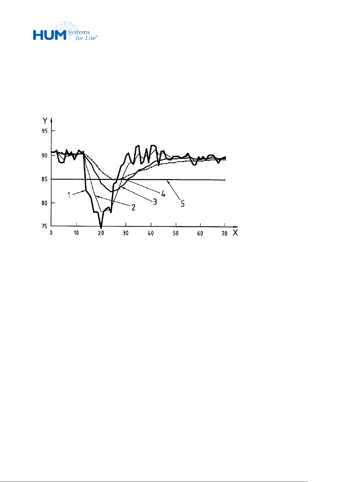
sat 805 Pulse Oximeter
Advanced Information
12 Advanced Information
12.1 Averaging Time
This figure represents a faster desaturation slope and a more realistic, noisier saturation signal curve 1).
Curves 3 and 4 underestimate the depth of the fall in saturation. Curve 2, faster averaging, can cross a low
saturation alarm limit sooner than curve 3, normal averaging, or curve 4, slower averaging, which might
not cause an alarm condition at all. The benefit of normal and slower averaging is to smooth out the
otherwise noisy signal and reduce the number of false positive alarm conditions.
97
Page 98
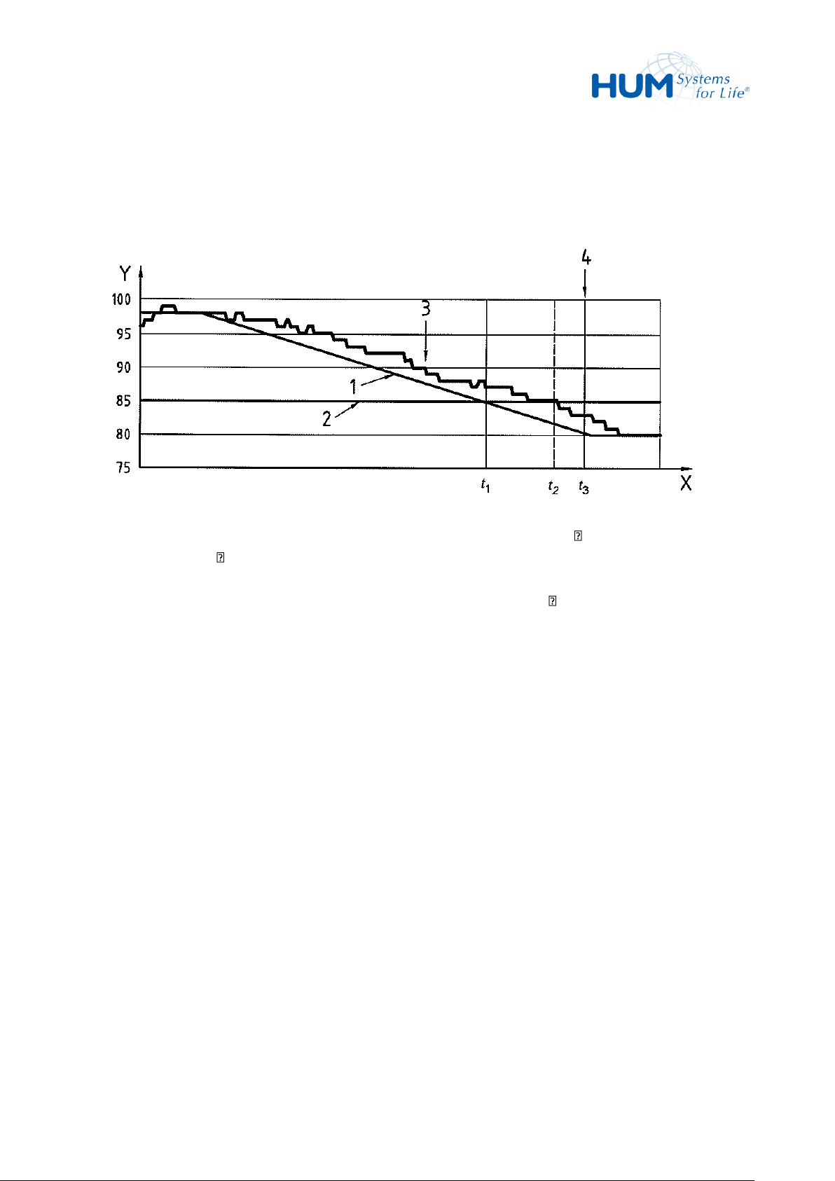
sat 805 Pulse Oximeter
Advanced Information
12.2 Alarm Signal Generation Delay
Graphic Representation of Components of Alarm System Delay:
The delay due to the pulse oximeter equipment processing and averaging is t2 - t1, the alarm condition
delay. The interval t3 - t2, the alarm signal generation delay, is attributed to the alarm system strategy and
the communication time to the alarm signal generation device or distributed alarm system (e.g. patient
monitor or central station). Thus, the overall alarm system delay time is t3 - t1.
98
Page 99

sat 805 Pulse Oximeter
Index
13 Index
A
Access permissions ........................................ 55
Accessories .................................................... 96
Acoustical alarms .......................................... 57
Advanced information ................................... 97
Alarm categories ........................................... 74
Alarm details ................................................. 69
Alarm filter .................................................... 50
Alarm limits ............................................. 18, 48
Alarm lists ...................................................... 67
Alarm signal generation delay ....................... 98
Alarm silence time ......................................... 59
Battery Alarm................................................ 82
C
Charging the batteries .................................. 29
Cleaning ........................................................ 89
Clinic ............................................................. 55
Clock ............................................................. 64
Combination of Alarms ................................. 83
Connecting the Patient cable ....................... 34
Connections .................................................. 32
Connections .................................................. 20
Contrast ........................................................ 53
Control .......................................................... 43
Alarm system ................................................. 25
Alarm tone mute ........................................... 59
Alarm tone volume ........................................ 58
Alarms ........................................................... 73
Analogue interface .................................. 24, 66
APOD ............................................................. 62
Artifact Filter ................................................. 63
Assembly ....................................................... 20
Averaging time ........................................ 60, 97
B
Backlight ........................................................ 54
Batteries ........................................................ 14
Controls ........................................................ 20
Copyright protection ...................................... 9
Customer Service .......................................... 15
D
Dangers ......................................................... 14
Data export ................................................... 71
Default settings ............................................. 19
Desinfection .................................................. 92
Device information ....................................... 65
Disinfection ................................................... 90
Display .......................................................... 20
Disposal........................................................... 9
99
Page 100

sat 805 Pulse Oximeter
Index
Disposal ........................................................ 28
E
Environmental Conditions ............................ 29
External Alarm .............................................. 65
F
FastSat™ ....................................................... 61
H
High priority alarms ...................................... 74
HomeCare ..................................................... 55
I
ID nameplate ................................................ 26
Inaccurate measurements ............................ 73
Info ................................................................ 65
M
Mains operation ............................................ 29
Mains power failure alarm ............................ 31
Maintenance ................................................. 93
Malfunctions ................................................. 84
Masimo Signal Processing ............................. 60
Masimo-Sensors ........................................... 35
Medium priority alarms ................................ 79
Menu ............................................................. 43
N
Normal Display .............................................. 46
Nurse call ...................................................... 65
Nurse Call alarm ............................................ 25
Installing the Unit ......................................... 34
Intended use ................................................. 11
Interfaces .................................................24, 42
L
Language ....................................................... 54
LC Display .................................................21, 22
Liability............................................................ 8
Life Times ...................................................... 19
Lifetimes of patient cables and sensors ....... 38
Loss of pulse signal ....................................... 74
Low priority alarms ....................................... 80
Low-level alarm ............................................ 81
O
Operating instructions .................................... 7
P
Packaging ...................................................... 28
Perf-Mode ..................................................... 61
Perfusion Sensitivity...................................... 61
Perfusions-Index ........................................... 22
PIN code ........................................................ 56
Possible misapplications ............................... 12
Pulse Rate Alarm ........................................... 75
Pulse tone volume ........................................ 57
R
Removal .......................................................... 9
 Loading...