


HDL 100
Operating instructions
EN

SCOPE OF DELIVERY FOR HDL 100-S:
1. Laser distance measurement instrument
2. Belt pouch
3. 1.2 V Ni-Mh battery
4. Charging /data cable
5. Tripod B-10
1
2
3
5
4
2

2.1 Function Buttons
2.2 Display
1
2
1
4
5
3
2
3
6
3

Operating manual
HDL 100 Laser Distance
Measurement Instrument
About this manual
Congratulations on the purchase of your
new HDL 100! You have acquired a Hultafors
measurement instrument, which can make
your work easier, faster and more precise. To
utilize the complete functionality range of this
measurement instrument, and to ensure a
safe operation, please observe the following
instructions:
• Please read these operating manual before
starting to use the device.
• Always keep the operating manual near the
device.
• Only hand over the device to other persons
together with the operating manual.
• Never render the attached warning signs
unreadable.
4
Contents
1. General information
2. Description
3. Technical data
4. Safety instructions
5. Laser safety / classification
6. Startup
7. Operation
8. Maintenance, storage and transportation
9. Scope of delivery and accessories
10. Troubleshooting
11. Di sp os al
12. Warranty
13. EC conformity declaration

1. General information
1.1 Signal words and their meaning
DANGER
For an imminent danger that could lead to
serious injury or death.
WARNING
For a possibly dangerous situation that could
lead to serious injury or death.
CAUTION
For a possibly dangerous situation that could
lead to slight injury or propert y damage.
NOTE
For application notes and other useful
information
1.2 Pictograms and other information
1.2.1 WARNING SIGNS
Warning of dangers in general
1.2.2 SYMBOLE
Read instructions before use
Batteries and devices must not be
disposed of with household waste
Do not throw batteries into a fire
Warning signs on batter y Do not
heat the battery above 60 °C.
Class 2 laser device
Do not look into the laser beam!
5

2. Description
1.2 Function Buttons
1. Measure button
2. ON / OFF/ Delete / Back
3. Camera
2.2 Display
1. Bluetooth
2. Unit of measurement
3. Measurement edge
4. Tilt sensor
5. Turn display
6. Measured value memory
2.3 Intended use
is instrument is designed to measure
distances and angle s. e measured value,
setting, tilt and instrument status can be viewed
on the display.
A laser beam is emitted and then sent back to
the laser distance measurement instrument
from a reflected sur face. is is used to calculate
the distance. e range depends on the model of
the laser distance measurement instrument, on
reflectivity, and on the properties of the reflective
surface.
6

3. Technical data
3.1 General
Measurement range 0. 2–100 m *
Accuracy ± 1.5 mm**
Unit of measurement m, in, , +in
Laser class 2
Laser type 635 nm, < 1 mW
Protection rating IP 54
Laser auto-shutdown 30 h
Instrument auto-shutdown 180 s
Operations per charge up to 5000 measurement s***
Battery type 3 x 1.2 V Ni-Mh batter y (3 x 850 mAh)
Operating temperature 0–40°C
Storage temperature -10– 6 0° C
Dimensions H x W x L 115 x 50 x 25 mm
Weight with batteries 110 g
*when measuring a target with 100% reflectivity (e.g. a painted white wall), with low backlight and an operating temperature of 25°C
**this degree of precision applies when measuring distances of between 0.2 and 10 m; when measuring distances of between 10 m and 100 m, the maximum
tolerance may decrease by 0.1 mm/m
***when used at room temperature
7

3.2 Functions
• Individual measurement
• Min/Max measurement
• Continuous measurement
• Area measurement
• Volume measurement
• Indirect 2-point measurement
• Indirect 3-point measurement
• Automatic distance measurement
• Indirect measurement via angle
• Indirect distance measurement
• Additon
• Subtraction
• Measured value memory
• Unit of measurement
• Tilt sensor
• Bluetooth
• Turn display
• Camera
8

4. Safety instructions
4.1 AREA OF RESPONSIBILITY
4.1.1 MANUFACTURER
Hultafors is responsible for the safe delivery
condition of the product, including the operating
manual and the original accessories.
4.1.2 OPERATOR
e operator is responsible for using the product
as intended, the deployment of personnel,
their training and the operational safet y of the
product.
• e operator understands the safety
information which is stated on the
product and the instructions which
are contained in the operating manual.
• e operator shall comply with local
regulations relating to safety and accident
prevention regulations as well as worker
protection laws and regulations.
• e operator shall immediately notif y Hultafors
if safety-related issues should develop on the
product or during its utilization.
• e operator shall ensure that the product
is not utilized any further if defects become
evident, and he will have the product repaired
professionally.
4.2 Improper Use
• Use of the device and the accessories without
instruction.
• Use of third-party accessories or additional
equipment.
• Use outside of the intended limits
3 / Technical data)
• Use under extreme temperature fluctuations
without an adequate acclimatization.
• Disabling of safety devices and removal of
hazard notices and labels.
• Unauthorized opening of the device.
• Performance of modifications or alterations
the device or the accessorie s.
• Deliberate blinding of third parties.
• Inadequate safeguarding at the installation
site.
.
(see Chapter
4.3 Utilization limitations
e HDL 100 is suitable for a continuous use
in an atmosphere which can be inhabited by
humans.
• Do not operate the product in explosion-prone
or corrosive environments.
• Inform the local safety authorities and
safety expert s before working in hazardous
environment s, in close proximity to electrical
installations or similar surroundings.
9

4.4 Usage Hazards
4.4.1 GENERAL
WARNING
Missing or incomplete instructions may
result in improper or incorrect use.
is can cause accidents with serious
damages to persons, property, assets
and the environment.
• Follow the manufacturer‘s and operator‘s
safety instructions.
• Protect equipment and accessories from
access by children.
WARNING
Blinding by laser radiation can indirectly
lead to serious accidents, especially
for people who are driving a vehicle or
operating machinery. Do not look into
the laser beam.
• Do not set up the laser beam and the laser
plane at eye level or aim at people.
CAUTION
A fall, longer storage, transportation or
other mechanical eects can lead to
erroneous measurement results. Check
the unit for damage before use.
Do not use damaged equipment.
• Repairs have to be exclusively performed by
Hultafors
4.4.2 BATTERIES
DANGER
Mechanical damage can lead to
a leakage, fire or explosion of the
batteries or trigger the release of toxic
substances.
• Batteries and rechargeable bat teries may not
be opened or exposed to mechanical loads.
• Repairs have to be exclusively performed by
Hultafors.
WARNING
High ambient temperatures and
immersion into liquids can cause
a leakage, fire or explosion of the
batteries or trigger the release of toxic
substances.
• Protect batteries from mechanical damage
during transpor t.
• Do not overheat batteries and rechargeable
batteries or expose them to fire.
• Avoid the ingress of moisture into batteries
and rechargeable bat teries.
• Do not use damaged batteries or rechargeable
batteries. Per form a proper disposal
(see Chapter 11 / Disposal)
WARNING
A short-circuiting or unintended use can
cause batteries to overheat and create
an injury or fire hazard.
.
10

• Do not transport or store batteries in the
pockets of garments.
• Do not bring the batter y contacts in contact
with jewelery, keys, or other electrically
conductive objects.
• Do not charge the batteries.
• Do not discharge the batteries through shortcircuiting.
• Do not solder the batteries within the device.
• Do not mix old and new batteries, and do not
mix batteries from dierent manufacturer s or
with a diering type designation.
WARNING
If disposed of improperly third parties
can possibly be seriously injured and
the environment polluted. e burning
of plastic components generates toxic
fumes which may impair health of
people. Batteries / rechargeable
batteries may explode if they are
damaged or heated excessively,
and thereby cause poisoning,
burning, corrosion or environmental
contamination.
If disposed of negligently unauthorized
persons are able to use the product
improp erly.
• e product may not be disposed of together
with household waste. Dispose of the device
and accessories properly.
(see Chapter 12 / Dispo sal).
• Protect the product at all times from access by
unauthorized persons, and especially children.
4.5 Electromagnetic compatibility (EMC)
e electromagnetic compatibility is the ability of
the product to function in an environment where
electromagnetic radiation and electrostatic
discharges are present, without causing an
electromagnetic interference for other devices.
4.5.1 INTERFERENCE OF OTHER DEVICES OF
HDL 100
Although the product meets the strict
requirement s of the relevant directives and
standards, Hultafors can not completely
exclude the possibility of interference with other
devices (for example, when using the product in
combination with third-party devices, such as
field computers, personal computers, wireles s
devices, mobile phones, cer tain cables or
external batteries).
• When using computers and radio equipment
make sure to observe the vendor-specific
information about electromagnetic
compatibilit y.
• Only use original Hultafors equipment and
accessories.
11

4.5.2 INTERFERENCE OF THE HDL 100 BY
OTHER DEVICES
Although the product meets the strict
requirement s of the relevant directives and
standards, Hultafors can not entirely exclude the
possibility that intense electromagnetic radiation
in the immediate vicinity of radio transmitters,
two-way radios, diesel generators, etc. can
distort the measurement results.
• When performing measurements under these
conditions check the plausibility of the results.
12

5. Laser safety/classification
e HDL 100 emits a visible laser point.
e product corresponds to the Class 2 Laser
according to DIN EN 60825-1:2007
Class 2 Laser:
When using Class 2 laser devices the eye is
protected by the blink reflex or aversion reaction
in case of a random and shor t-term exposure.
WARNING
Looking directly into the beam with
optical aids (e.g. binoculars, telescopes)
can be dangerous.
WARNING
Looking into the laser beam may be
hazardous to the eye.
• Do not look into the laser beam.
• Do not aim the laser beam at other people.
Labelling on the device:
• Do not remove the type plate!
13

6. Getting Started
6.1 Batteries
1. Open battery compartment cover on the back
of the instrument by sliding it down.
2. Insert the batteries into the instrument,
observing the correct polarity.
3. Close battery compar tment by sliding the
cover back into place.
Remove the batteries if the instrument is not
used over a longer period of time.
6.2 Belt Pouch
e laser instrument can be stowed in a belt
pouch for transpor t. It must be removed from the
pouch when taking measurements.
14
7. Operation
7.1 Getting Started
7.1.1 SWITCHING THE INSTRUMENT ON AND OFF
On:
• Hold down the ‘ON/OFF/Delete/Back button’
for 2 seconds to switch the laser instrument on.
O:
• Hold down the ‘ON/OFF/Delete/Back button’
for 2 seconds to switch the laser instrument o.
7.1 .2 B AC K
Press the ‘ON/OFF/Delete/Back button’ once
in order to cancel the previous process. Press
the ‘ON/OFF/ Delete/Back button’ twice to exit
the current function and return to individual
measurement mode.
7.1.3 SETTING THE MEASUREMENT PLANE
Use the touch display to access the menu. Pres s
the Measurement edge icon to toggle between
the front, thread and back of the instrument.
e selection is indicated by an arrow on the
display. e back of the instrument is set as
the measurement edge by default. Each time
the instrument is restarted, the back of the
instrument is reset as the measurement edge.
7.2 Applications
7.2.1 INDIVIDUAL MEASUREMENT
1. Switch on the laser instrument.
2. Direct the laser point at the target.
3. Press ‘measure button’.
As soon as an audible signal is emitted, the
measurement is complete and the distance can
be seen on the display. To calculate additional
distances, press Measure button again.
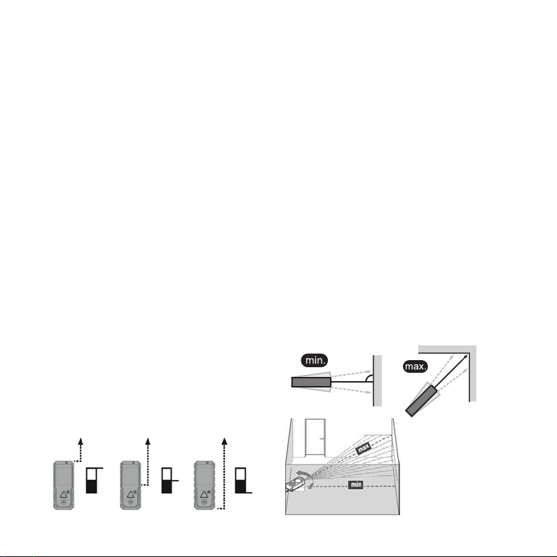
7.2.2 MIN/MAX MEASUREMENT
1. Switch on the laser instrument.
2. Direct the laser point at the target.
3. Press ‘measure button’ for 2 seconds.
e minimum and maximum values are shown
on the display. To stop the measurement, simply
press ‘measure button’.
15

7.2.3 CONTINUOUS MEASUREMENT
1. Switch on the laser instrument.
2. Direct the laser point at the target.
3. Press ‘measure button’ for 2 seconds.
e laser instrument measures the distance and
shows it on the bottom line of the display.
7.2.4 AREA MEASUREMENT
1. Switch on the laser instrument.
2. Choose the area measurement icon in the
functions menu.
3. Measure the length and then the
width separately using the individual
measurement method. e laser beam
remains switched on between the two
measurements.
Once the second measurement is complete,
the area is automatically calculated and shown
on the bottom line of the display. e individual
measured values are shown in measured value
lines 1 and 2. e perimeter is also shown in
measured value line 3.
7.2.5 VOLUME MEASUREMENT
1. Switch on the laser instrument.
2. Choose the volume measurement icon
in the functions menu.
3. Measure the length, the width, and
then the height separately using the
individual measurement method.
e laser beam remains switched on
between the three measurements.
Once the third measurement is complete,
the volume is automatically calculated and
shown on the bottom line of the display. e
individual measured values are shown in
measured value lines 1, 2, and 3.
16

7.2.6 INDIRECT 2-POINT MEASUREMENT
1. Switch on the laser instrument.
2. Choose the indirect 2-point measurement
icon in the functions menu.
3. Measure the two points separately using
the individual measurement method. e
laser beam remains switched on bet ween
the two measurements.
7.2.7 INDIRECT 3-POINT MEASUREMENT
1. Switch on the laser instrument.
2. Choose the indirect 3 -point measurement
icon in the functions menu.
3. Measure the three points separately using
the individual measurement method. e
laser beam remains switched on bet ween
the three measurements.
Once the second measurement is complete, the
length is automatically calculated and shown on the
bottom line of the display. e individual measured
values are shown in measured value lines 1 and 2.
Once the second measurement is complete, the
length is automatically calculated and shown
on the bottom line of the display. e individual
measured values are shown in measured value
lines 1 and 2.
CAUTION
e two points measured must be in line
and the second measurement must be
taken at a right angle to the measured
surface; otherwise measured values
may be incorrect.
Once the third measurement is complete, the
length is automatically calculated and shown
on the bottom line of the display. e individual
measured values are shown in measured value
lines 1, 2, and 3.
CAUTION
e three points measured must run
in a line and the second measurement
must be taken at a right angle to the
measured surface; otherwise measured
values may be incorrect.
17

7.2.8 AUTOMATIC DISTANCE MEASUREMENT
1. Switching on the laser instrument.
2. Choose the automatic distance
measurement icon in the functions menu.
3. e measurement is taken in the same
manner as a single measurement.
Once this has been completed, the length
is calculated automatically and is shown in
the bottom line of the display. e measured
distance and height are displayed in measured
value lines 1 and 2.
7.2.9 INDIRECT MEASUREMENT VIA ANGLE
1. Switching on the laser instrument.
2. Choose the indirect measurement via angle
icon in the functions menu.
3. Measure the two points separately using
the individual measurement method. e
laser beam remains switched on bet ween
the two measurements.
Once the second measurement is complete, the
length is automatically calculated and shown
on the bottom line of the display. e individual
measured values are shown in measured value
lines 1 and 2.
CAUTION
e two points measured must be in line
otherwise the measured values may be
incorrect.
18
CAUTION
e two points measured must be in line
otherwise the measured values may be
incorrect.

7.2.10 INDIRECT DISTANCE MEASUREMENT
1. Switching on the laser instrument.
2. Choose the indirect distance measurement
icon in the functions menu.
3. Measure the two points separately using
the individual measurement method. e
laser beam remains switched on bet ween
the two measurements.
Once the second measurement is complete, the
length is automatically calculated and shown
on the bottom line of the display. e individual
measured values are shown in measured value
lines 1 and 2.
CAUTION
e two points measured must be in line
otherwise the measured values may be
incorrect.
7.2.11 ADDITION
1. Switch on the laser instrument.
2. Direct the laser point at the target.
3. Take an individual measurement.
4. Choose the addition (+) icon in the
calculation menu (plus symbol + appear s on
the display).
5. Take an individual measurement.
e laser instrument shows the result on the
bottom line of the display. is process can be
repeated as many times as required.
7.2.12 SUBTRACTION
1. Switch on the laser instrument.
2. Direct the laser point at the target.
3. Take an individual measurement.
4. Choose the subtraction (+) icon in the
calculation menu (minus symbol - appears
on the display).
5. Take an individual measurement.
e laser instrument shows the result on the
bottom line of the display. is process can be
repeated as many times as required.
7.2.13 MEASURED VALUE MEMORY
1. Switch on the laser instrument.
2. Use the touch display to access the menu.
Choose measured value memory icon.
Swipe to le or right on the touch display to
toggle between measured values.
3. By pressing the camera button, single
measuring results can be deleted.
7.2.14 UNIT OF MEASUREMENT
1. Switch on the laser instrument.
2. Use the touch display to access the menu.
Choose measured value icon.
Pressing the icon switches the measurement
unit from ‘m’ to ‘’ then to ‘in’ and then ‘+in’.
Each time the instrument is restarted, the unit of
19

measurement is reset to the measurement unit
that was last used.
7.2.15 TILT SENSOR
1. Switch on the laser instrument.
2. Use the touch display to access the menu.
Choose inclinometer icon.
e display shows a tilt sensor that displays the
degrees in both axial directions.
7.2.16 BLUETOOTH
1. Switch on the laser instrument.
2. Use the touch display to access the menu.
Select Bluetooth icon.
Bluetooth can be activated and deactivated by
pressing the icon.
Bluetooth M is for manual connection, Bluetooth
A is for automatic connection.
Fast and ecient data transfer of measured
values can be made directly to a smartphone via
Bluetooth.
NOTE
To pair with a smartphone, launch
the HDL 100 Measure & Sketch app
and connect using one of the function
options.
7.2.17 TURN DISPLAY
1. Switch on the laser instrument.
2. Use the touch display to access the menu.
Choose turn display icon.
e turn display function can be activated and
deactivated by pressing the icon.
7.2 . 18 CAMER A
1. Switch on the laser instrument.
2. Direct the laser point at the target.
3. Press ‘camera button’.
e display shows an image of the surroundings.
By pressing the ‘camera button’ again, you can
toggle between 2 and 4 x zoom. e cross hairs
in the centre of the display can help find the laser
point.
4. Press ‘measure button’.
e result will appear in the bottom line of the
display.
7.3 Guidance for Operation
e laser instrument must not be moved while
measuring. A fixed mounting surface with a stop
is therefore recommended. e laser outlet
and receiving area must not be covered during
measuring. Depending on the measured surface,
it cannot be guaranteed that all measurements
are completely accurate. Avoid surfaces that are
textured, reflective, transparent, or porous.
20

8. Maintenance, storage and transportation
8.1 Cleaning
• Wipe o the dir t with a so damp cloth.
• Check the outlet openings of the laser
regularly, and thoroughly clean them if
necessary. Do not touch the glass with your
fingers.
• Do not use ag gressive cleaning agents or
solvents.
• Do not immerse the device into water!
• Clean and dry wet equipment, accessories
and transport containers prior to packaging
them. Only pack equipment again when it is
completely dry.
• Keep plug connections clean and protected
from moisture.
8.2 Storage
8.2.1 GENERAL
• e equipment may only be stored within the
specified temperature limits
(see Chapter 3 / Technical dat a).
• Aer prolonged storage check the accuracy of
the measuring device before using it.
8.2.2 BATTERIES
• For storage, remove the batteries from the
device or from the charging station.
• e storage should preferably be in a dry
environment at room temperature
(see Chapter 3 / Technical dat a).
• Protect from moisture and humidity. Dr y wet or
damp batteries before storage before usage.
8.3 Transport
8.3.1 GENERAL
e device may be damaged by strong vibrations
or by falling.
• Never transport the product loose. Always
use the original packaging or an equivalent
transport container.
• Switch o the measuring device before
transporting it.
• Check the unit for damages before use.
8.3.2 BATTERIES
When transporting or shipping batteries, the
operator is responsible for complying with the
applicable national and international laws and
regulations.
• Before shipping, remove the batteries from the
device.
21

9. Delivery contents and accessories
9.1 Delivery contents of HDL 100-S
1 Laser distance measurement instrument
3 1.2 V Ni-Mh batteries
1 Belt pouch
1 Charging /data cable
1 B-10 Tripod
9.2 ACCESSORIES (optional)
LB laser gog gles
TP target plate
Further information on accessories can be found
at www.hultafors.com
22

10. Troubleshooting
Error Possible cause Remedy
204 • Calculation error • Check specifications.
208 • Overvoltage • Contact supplier.
220 • Battery empty • Replace battery.
252 • Temperature too high • Allow instrument to cool to the
253 • Temperature too low • Allow instrument to warm up to
255 • Reception signal too weak • Increase reflectivity of target.
256 • Reception signal too strong • Limit reflectivity of target.
261 • Outside of measurement range • Observe measurement range
500 • Component error • Switch instrument on and o
Repeat process.
specified temperature.
the specified temperature.
given in specifications.
repeatedly.
If the error continues, contact
the supplier.
23

12. Disposal
If disposed of improperly third parties can
possibly be seriously injured and the
environment polluted.
e burning of plastic components generates
toxic fumes which may impair the health of
people.
Batteries may explode if they are damaged
or heated excessively, and thereby cause
poisoning, burning, corrosion or environmental
contamination.
If disposed of negligently unauthorized persons
may be able to use the product improperly.
Measuring tools, accessories and packaging
must be recycled in an environmentally-friendly
manner.
e product as well as the
accessories - especially the
batteries and rechargeable
batteries - must not be disposed
of with household waste.
• Dispose of the device and the
accessories properly
• Only dispose of batteries in a
discharged state.
• Observe the country-specific
disposal requirements.
Your Hultafors dealership will take back batteries
as well as old equipment, and will ensure proper
disposal.
Only for EU countries
Electric tools may not be
disposed of with household
waste!
According to the European
Directive 2002 / 96 / EC on
Waste Electrical and Electronic
Equipment and it s
implementation in national law,
no longer usable electrical and
electronic equipment must
be collected separately and
recycled in an environmentally
friendly manner.
24

13. Manufacturer‘s Guarantee
e manufacturer warrants to the original
purchaser stated on the guarantee card, freedom
from defects the device for a period of two years,
with the exception of batteries, as of the point in
time the device is handed over. e guarantee
is limited to repairs and / or replacement s at
manufacturer‘s discretion.
Defect s which are caused through improper
handling by the purchaser or third parties, natural
wear and optical flaws that do not aect the
usability of the equipment, are not covered by
this guarantee. Claims under this guarantee can
only be invoked if the device is submitted along
with the guarantee card, completely filled out by
the dealer, dated and provided with the company
stamp. If the guarantee claim is justified, the
manufacturer shall bear the transport costs. e
duration of the guarantee will not be extended
through repair or spare par ts work which is carried
out within the scope of the guarantee.
Further claims are excluded, unle ss there are
provided by the respective national legislation. In
particular the manufacturer shall not be liable for
any direct, indirect, incidental or consequential
damages, losses or expenses in connection with
the use or because of the inability to use the tool
for any purpose whatsoever.
Implied warranties for the usage or suitability for a
particular purpose are expressly excluded.
25

14. EC conformity declaration
Declaration of Conformity
We Hultafors Group AB, Hultaforsvägen 21, Hultafors
declare under our sole responsibility that the Product(s)
to which this declarations relates is in conformity with the following standards.
HDL 100:
• EN 55022: 2010
• EN 61000
• EN 55024: 2010
• EN 60825-1:2007
Following the provisions of Directive(s)
HDL 100
26
Electromagnetic compatibility 2004 / 108 / EC
Low Voltage Directive 2006 / 95 / EC

MARCH 2018 v.1
 Loading...