

Page 1
Copyright by Hukseflux | manual v1902 | www.hukseflux.com | info@hukseflux.com
USER MANUAL
TCOMSYS01 Hot Cube
Thermal comfort measuring system
Hukseflux
Thermal Sensors
Page 2
TCOMS YS01 man u al v19 0 2 2/47
Warning statements
Putting a voltage of over 30 VDC to TCOMSYS01
may result in permanent damage to the system.
TCOMSYS01 has an internal battery in the MCU that
powers the clock and the SRAM when external power
is not supplied. If the battery is exhausted, contact
the factory for instructions.
Connect both cables to the TCOM01 sensor body and
the MCU before turning on the MCU.
TCOM01 contains a resettable temperature fuse,
which limits use to 60 °C.
Page 3

TCOMSY S 01 manu a l v190 2 3/47
Contents
Warning statements 2
Contents 3
Introduction 4
1 Ordering and checking at delivery 11
1.1 Ordering TCOMSYS01 11
1.2 Included items 11
2 Instrument principle and theory 13
2.1 MCU Measurement and Control Unit 13
2.2 TCOM01 sensor body 14
3 Specifications of TCOMSYS01 Hot Cube 16
3.1 Dimensions of TCOMSYS01 19
4 General directions for performing a measurement of thermal comfort 20
5 Installation 21
5.1 Electrical connection 21
5.2 Mechanical setup 22
5.3 Software installation 23
5.4 Set the TCOMSYS01 clock 25
6 Working with the system 27
6.1 Basic functionality 27
6.2 Data retrieval 29
6.3 Example experiments 31
7 Maintenance and trouble shooting 35
7.1 Recommended maintenance and quality assurance 35
7.2 Trouble shooting 36
8 Appendices 39
8.1 Advanced settings 39
8.2 Ordering the TCOM01 sensor only 41
8.3 EU declaration of conformity TCOMSYS01 44
8.4 EU declaration of conformity TCOM01 45
Page 4
TCOMSY S 01 manu a l v190 2 4/47
Introduction
TCOMSYS01 is a measuring system to help understand and quantify “causes and effect”
leading to human thermal comfort. The TCOM01 body is temperature stabilised at 33 °C,
so that it offers a relatively direct measurement of the human experience. In essence,
TCOM01 is a miniature thermal mannequin, measuring according to the innovative Hot
Cube method. The heater power required to keep the TCOM01 at a constant temperature
is the main measurand. Incorporating 5 heat flux sensors with a black absorber, it also
offers a detailed picture of the heat gain and loss from different directions, and a good
indication of convective and radiative asymmetry. Other measurements are sensor body
temperature, air temperature and relative humidity. In its standard configuration, the
system consists of an MCU (Measurement and Control Unit) and a TCOM01 sensor. The
MCU offers direct connection to any local area network and “Ethernet over USB”. TCOM01
is also available as a sensor only.
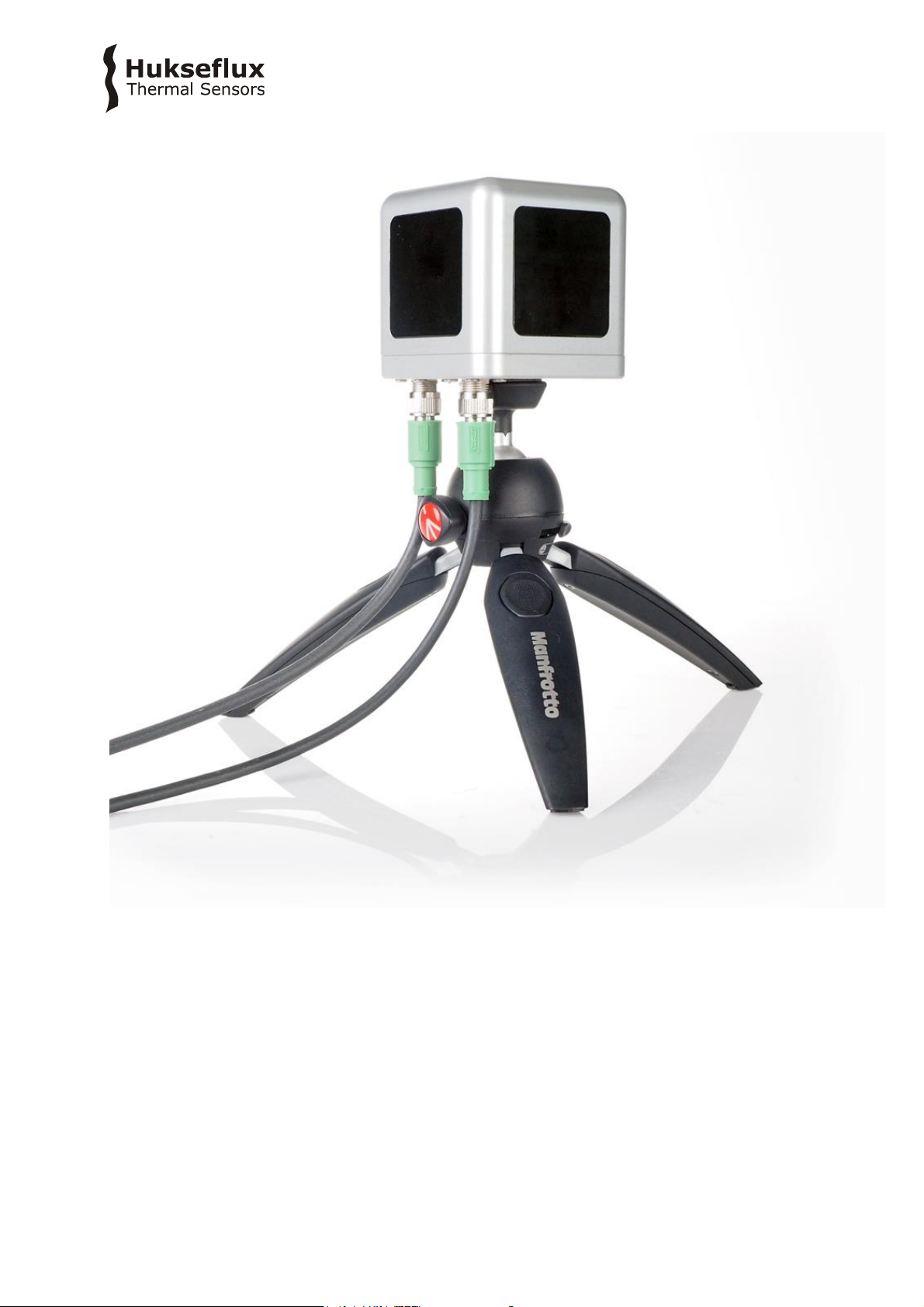
Figure 0.1 The TCOM01 sensor body on a tripod. TCOM01 is meant for surveys of
thermal comfort as experienced by the human body. It is equipped with 5 x heat flux
sensor (black surfaces) and a sensor body temperature sensor. Heater power, ambient
temperature and relative humidity are measured in the accompanying MCU
(Measurement and Control Unit)
Page 5
TCOMSY S 01 manu a l v190 2 5/47
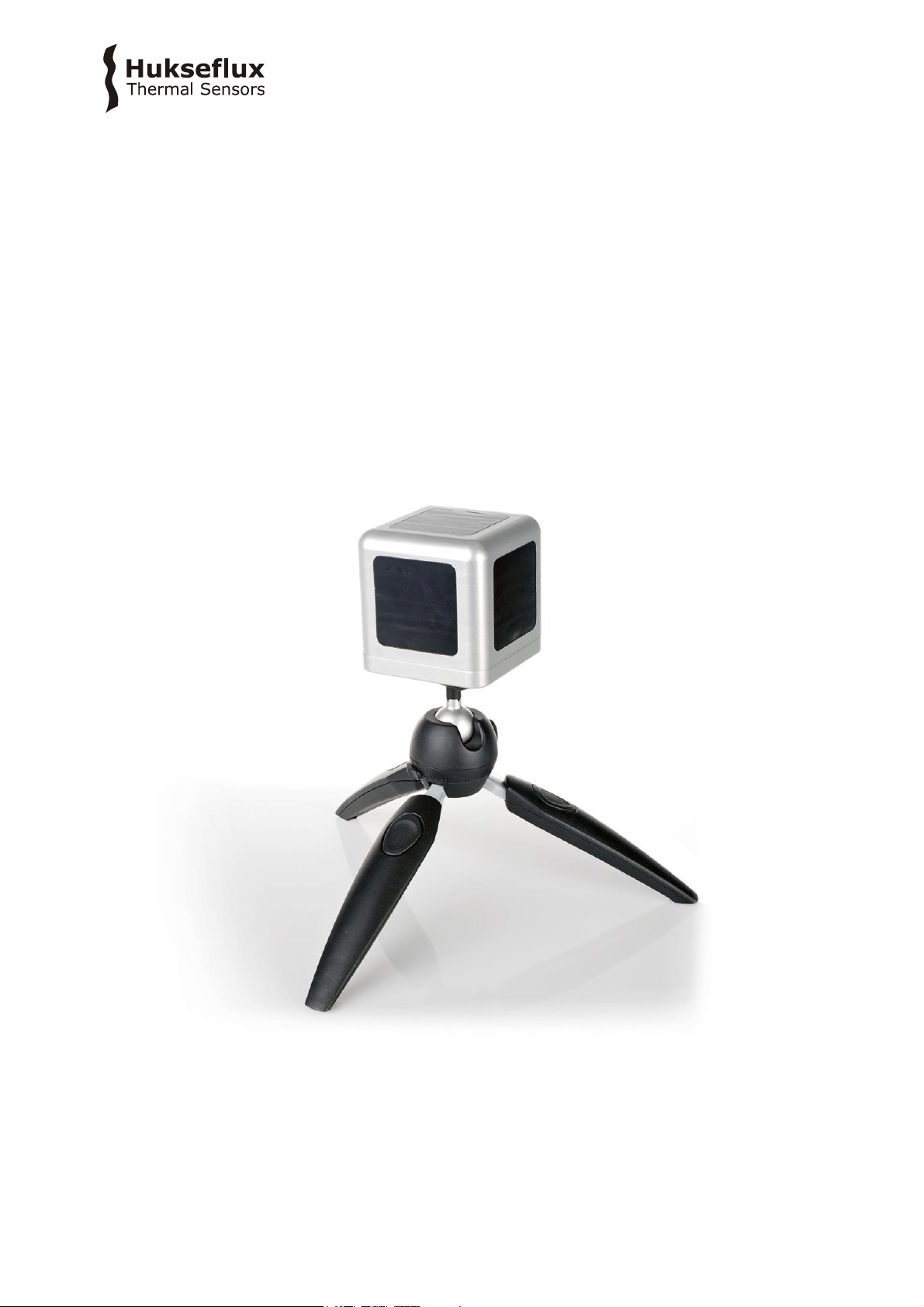
Figure 0.2 Overview of TCOMSYS01: (1) Ethernet port, (2) USB port, (3) MCU
Measurement and Control Unit, (4) air temperature and relative humidity sensor,
(5) TCOM01, (6) side panel: heat flux sensor with black absorber foil, (7) connectors (not
visible), (8) tripod
TCOMSYS01 was originally designed to study the effect of radiation sources on human
comfort. Equipped with heat flux sensors that measure in 5 directions and a humidity and
temperature probe, it offers a good picture of energy gains and losses from all sides to a
metal body that thermally resembles the human body; the TCOM01 sensor is in essence
a miniature thermal mannequin.
The TCOMSYS01 system employs dedicated sensors and electronics, measuring thermal
comfort according to the new Hot Cube method. The high accuracy of the MCU
(Measurement and Control Unit) ensures that TCOMSYS01 will still measure down to very
low heat fluxes. The MCU has robust aluminium housing. The system generates a
measurement file, including a time-stamp. The measurement data are stored in the MCU
and are later downloaded to a PC. The user is responsible for data analysis.
How to employ TCOMSYS01
The primary source of information from TCOMSYS01 simply is the power [W] required to
keep the TC0M01 sensor at a constant temperature; a very direct measure of human
comfort. This power may be compared to the power required at 20 °C ambient air
temperature, no convection (zero wind speed) and no radiation. Power consumption will
immediately show if there is a situation of overheating or heatstress or a situation of
overcooling or coldstress.
The second direct information supplied by the heat flux sensors of TCOMSYS01 is the
heat loss or gain [W/m2] as a function of direction. If radiative sources are dominant,
TCOMSYS01 will measure radiative asymmetry.
1
2
6
7
8
5
3
4
Page 6

TCOMSY S 01 manu a l v190 2 6/47
A web browser may be used for real time measurement review, data collection and for
changing control settings such as TCOM01 body temperature.
TCOMSYS01 advantages
• direct representation of the human body
• helps understand and quantify the detailed physical cause and effect of thermal
comfort
• simple experiments can be used to quantify the sources of heat gain or loss
• offers directional information
• good addition to Wet-Bulb Globe temperature measurement
• robust, student-proof
• “stand alone”; equipped with its own clock and memory
• safe, low voltage power supply
• communication by (virtual) Ethernet link
• user interface program on MCU
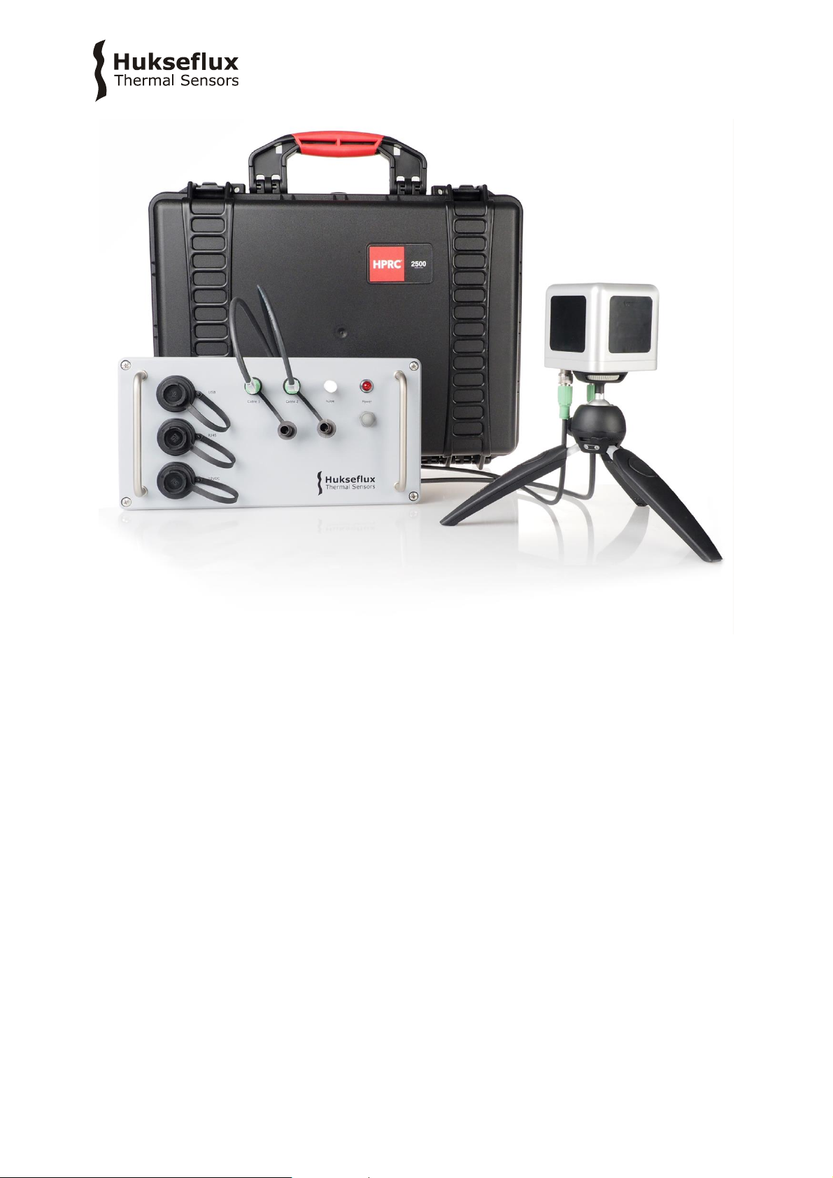
Figure 0.3 A complete system for measuring thermal comfort
Page 7

TCOMSY S 01 manu a l v190 2 7/47
Suggested use
• surveys of human thermal comfort
• studies of the effect of radiating sources
• workplace investigations
• car passenger comfort testing
• educational purposes, illustrating heat transfer
• bio-meteorology
• microclimate studies
• wind-chill analysis
• analysis of fabric insulation
Figure 0.4 TCOM01 applied in car passenger comfort testing
Page 8
TCOMSY S 01 manu a l v190 2 8/47
History
Already in 1929 the Eupatheoscope (from Greek “wellbeing–emotion–examination”) was
designed by A.F. Dufton to quantify the condition in a room from the point of view of
comfort. It consists of a blackened cylinder which is controlled to maintain a temperature
of 23 °C. The power used is interpreted in terms of equivalent temperatures.
In the 1990 the company Bruel & Kjear carried a thermal comfort meter (model 1212),
based on the same principle, and in addition processing Fangers equation.
Both models involved only an integrated power measurement. The new Hot Cube method
improves on this by incorporating omnidirectional heat flux measurements.
What makes TCOMSYS01 different
The main contributors to thermal comfort are air temperature, air speed, radiant
temperature and humidity. Apart from this, there are personal contributors such as
metabolic rate and insulation by clothing. Many studies use Fanger’s thermal comfort
equation as applied in EN ISO 7730: Moderate Thermal Environments - Determination of
the PMV and PPD indices and specification of the condition for thermal comfort. Another
approach utilises a globe temperature measurement: EN ISO 27243: Hot environments.
Estimation of the heat stress on working man, based on the WBGT Index (Wet Bulb
Globe Temperature). These methods are quite indirect in particular when determining the
heat flow from air speed and radiation.
• TCOMSYS01 offers heat flux measurements. This approach is a lot more direct than the
indirect estimate from air speed and radiation.
• TCOMSYS01 offers directional information.
• TCOMSYS01 works at a realistic skin temperature of 33 °C (user adjustable).
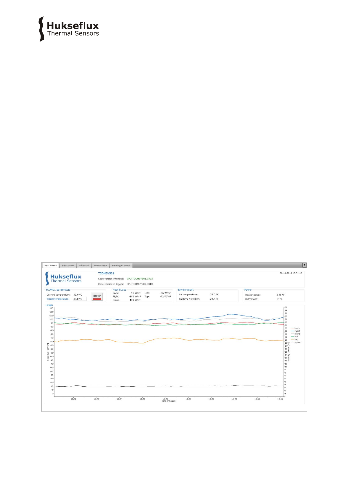
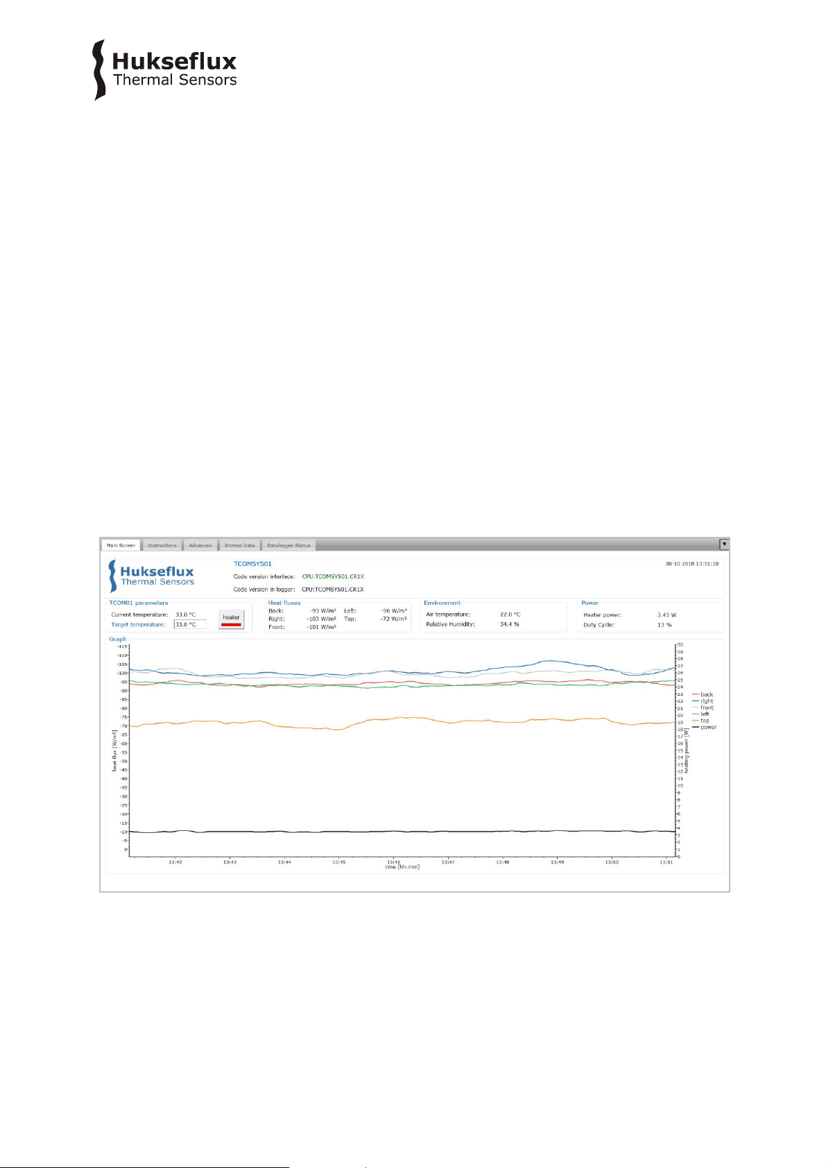
Figure 0.5 TCOMSYS01’s user interface: the main screen shows live data, and a graph
of the last 10 minutes
Page 9

TCOMSY S 01 manu a l v190 2 9/47
Rated operating conditions
TCOMSYS01 is designed to work between +10 and +25 °C. In its standard configuration,
uninsulated and stabilised at 33 °C, it is rated for operation in indoor conditions including
significant radiative heating.
It will stabilise at 33 °C under approximately one of the following conditions:
• air speeds < 5 m/s
• irradiance < 400 W/m
2
• ambient air temperature > 5 °C
Under other conditions, the sensor may not be able to stabilise its body temperature due
to overheating (indicating overheating or heatstress) or shortage of electrical power
(indication of overcooling or coldstress). Powered using a low voltage, TCOMSYS01 is safe
to use.
TCOMSYS01 may be used for short-term outdoor experiments in the order of weeks. Under
long-term exposure to solar radiation, the black heat flux sensor coating may become more
reflective.
User interface: MCU is a web server
The MCU serves as a web server, and can be connected to any local area network. No
more downloading of USB drivers and special interface software! Alternatively it offers an
“Ethernet over USB” or virtual Ethernet link, where you connect to the MCU using a USB
cable. If you type into your web browser the MCU’s IP address (192.168.66.1 by default),
you have access to the user interface.
Ordering the TCOM01 sensor only
The sensor TCOM01 is also available as a “sensor only”. The configuration then includes
the mannequin with 5 x heat flux, 1 x temperature, 1 x heater, 2 x cable, 2 x chassis
connector and 1 x tripod. The user then must combine it with his or her own
measurement and control unit.
Options
• TCOM01 sensor only
• extended rated operating conditions; temperature, irradiance, wind speed
See also
• our complete product range of heat flux sensors
• view the TRSYS01 building thermal resistance measuring system which includes 2 x
HFP01 sensor and 4 x matched thermocouple type K
Page 10
TCOMSY S 01 manu a l v190 2 10/47
Figure 0.6 TCOM01 is also available as a “sensor only”
Page 11

TCOMSY S 01 manu a l v190 2 11/47
1 Ordering and checking at delivery
1.1 Ordering TCOMSYS01
The standard configuration of TCOMSYS01 is with 2 x 1.5 m cable
Common options are:
• TCOM01 sensor only (see the appendices of this user manual for what is included)
• extended rated operating conditions; temperature, irradiance, wind speed
1.2 Included items
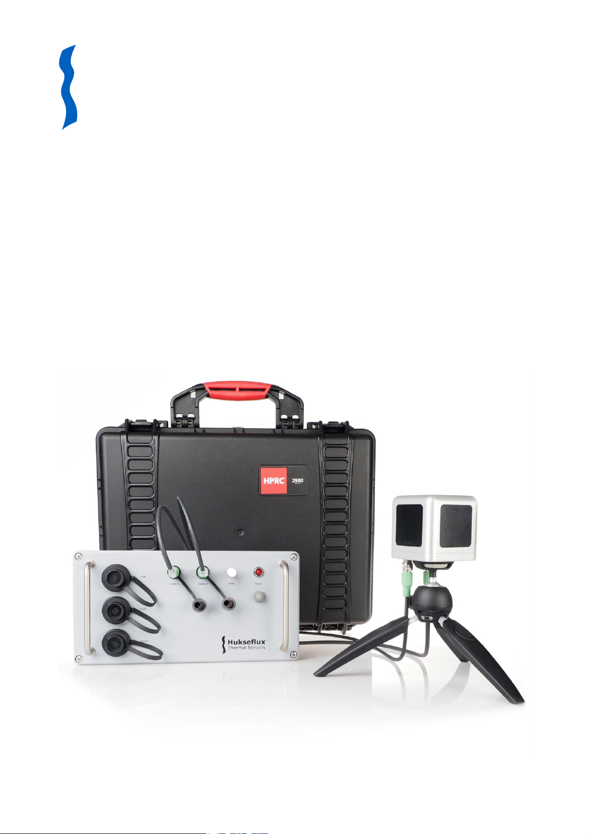
Arriving at the customer, the delivery should include:
• 1 x HPRC 2500 carrying case
• 1 x TCOMSYS01 thermal comfort measuring system
o 1 x TCOM01 thermal comfort sensor
o 1 x MCU Measurement and Control Unit
• 1 x 5 pin PHOENIX CONTACT cable, 1.5 m
• 1 x 8 pin PHOENIX CONTACT cable, 1.5 m
• 1 x Manfrotto PIXI EVO 2 tripod
• 1 x USB cable with Bulgin connector, 2 m
• 1 x Bulgin connector for Ethernet cable
• 1 x 12 VDC adapter, 1 m, supplied with 4 interchangeable AC plugs (AUS, EU, GBR, USA)
• 1 x product certificate
Page 12
TCOMSY S 01 manu a l v190 2 12/47
Figure 1.2.1 TCOMSYS01 with its MCU and carrying case
Page 13

TCOMSY S 01 manu a l v190 2 13/47
2 Instrument principle and theory
2.1 MCU Measurement and Control Unit
The MCU Measurement and Control Unit is specified to measure the current draw of the
heater, the voltage output of the heat flux sensors and the resistance of the 10 kΩ
thermistor (for TCOM01 body temperature).
The MCU performs the calculation of heater power, heat fluxes and temperature. It acts
as a PID controller to stabilise the TCOM01 body temperature at the required
temperature. The default setting of the body temperature is 33 °C. This may be adjusted
via the user interface.
The MCU interfaces with the humidity module to provide an ancillary measurement of
ambient air temperature and relative humidity.
The software, calibration data and user interface are stored on the MCU.
The MCU stores measurement data on a 8 GB Micro SD card.
2.1.1 Ambient air temperature and relative humidity
The MCU interfaces with a Vaisala HMM105 humidity module, to provide an ancillary
measurement of ambient air temperature and relative humidity.
Page 14
TCOMSY S 01 manu a l v190 2 14/47
2.2 TCOM01 sensor body
The TCOM01 sensor body is an aluminium body that is stabilised at a default temperature
of 33 °C. It is equipped with five FHF01 heat flux sensors with black absorbers to monitor
radiative and convective losses in five directions.
The connectors are in the ‘neck’ of the TCOM01, this defines the orientation of the black
surfaces (top, front, left, right, back).
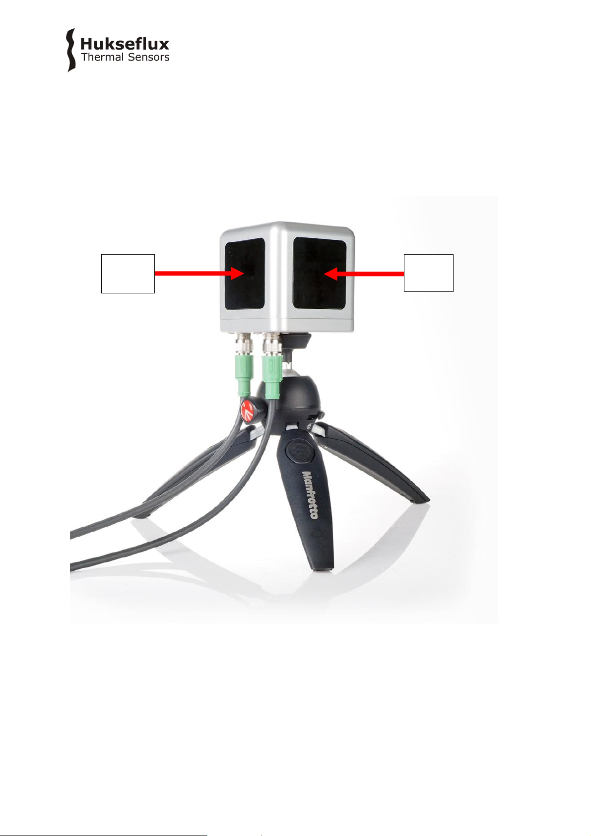
Figure 2.2.1 TCOM01 consists of on aluminium body (1) that is stabilised at a user
adjustable 33 °C using an internal heater. It is equipped with five FHF01 heat flux
sensors (2) with a black absorptive coating and an internal sensor body temperature
measurement
right
back
Page 15

TCOMSY S 01 manu a l v190 2 15/47
2.2.1 Heater
TCOM01 is powered using a thin film heater of around 4 Ohm, with a maximum power
rating of 40 W. The heater power is measured using a current measurement in the MCU
and combines this with the electrical resistance of the heater and a correction for the
voltage drop over the cables. The exact heater resistance is part of the system
calibration.
Temperature stabilisation of the TCOM01 body is achieved by pulse width modulation on
the power supplied to the heater. The ‘duty cycle’ (the percentage of time the heater is
powered) of this pulse width modulation is determined by the PID controller.
2.2.2 FHF01 foil heat flux sensors
The incorporated heat flux sensors are Hukseflux model FHF01 foil heat flux sensors.
FHF01s measure the heat flux density through the surface of the sensor. This quantity,
expressed in W/m², is called heat flux. Working completely passive, using a thermopile
sensor, FHF01s generate a small output voltage proportional to this flux.
All FHF01s are individually calibrated, and their sensitivities are programmed into the
software. The sensitivities can also be found on the product certificate.
For more information on FHF01, please refer to the FHF01 user manual.
To make the heat flux sensors sensitive not only to convective heat flux but also to
radiative heat flux, the FHF01s are covered with an adhesive black foil.
2.2.3 Body temperature sensor
Body temperature is measured using a 10 kΩ thermistor inside the TCOM01 body. The
MCU measures the resistance of this thermistor and converts this to temperature.
Page 16

TCOMSY S 01 manu a l v190 2 16/47
3 Specifications of TCOMSYS01 Hot Cube
TCOMSYS01 is a measuring system for “causes and effect” analysis leading to human
thermal comfort. The measurement method is called Hot Cube method. The TCOM01
body is temperature stabilised, normally at 33 °C. The heater power required to keep the
TCOM01 at a constant temperature is the main measurand. TCOM01 includes 5 heat flux
sensors with a black absorber, measuring the heat gain and loss from different
directions. Other measurements are sensor body temperature, air temperature and
relative humidity.
Table 3.1 Specifications of TCOMSYS01 (continued on next page)
TCOMSYS01 HOT CUBE SPECIFICATIONS
Description
thermal comfort measuring system
Measuring method
Hot Cube method
Measurand
heating power for stabilisation
Measurand in SI units
power in W
Measurand
heat flux (5 x)
Measurand in SI units
heat flux density in W/m²
Measurand
TCOM01 body temperature
Measurand in SI units
temperature in °C
Measurand
ambient air temperature
Measurand in SI units
temperature in °C
Measurand
relative humidity
Measurand in SI units
relative humidity in %
TCOM01 heat flux sensors
5 x FHF01 foil heat flux sensor
TCOM01 temperature sensor
10 kΩ thermistor
TCOM01 heater
3.6 Ω (nominal value), 40 W
Limiting temperature range
-25 to +50 °C
Thermal fuse protection limit
60 °C; to reset the thermal fuse, cool down the
TCOM01 and turn the MCU [OFF]
Temperature setting
33 °C (user adjustable)
Start up interval
< 10 min
Standard rated operating temperature
range (for temperature stabilisation)
10 to 25 °C
Rated air speed for temperature
stabilisation
< 2 m/s
Rated irradiance for temperature
stabilisation
< 400 W/m²
IP protection class
IP65 (TCOM01)
IP65 (MCU)
Rated operating relative humidity range
0 to 100 %
Included cables
2 x cable with 2 connectors (1.5 m)
USB cable (2 m)
connector for waterproof Ethernet connection
Data display
in web browser
Mounting
photo-tripod with ¼ inch -20 UNC screw
Manfrotto Pixi EVO 2 section black tripod is included
Gross weight TCOMSYS01 system
including carrying case and packaging
10.4 kg
Net weight TCOMSYS01 system
including carrying case
10.0 kg
Packaging TCOMSYS01 system
box of 500 x 400 x 250 mm
Carrying case TCOMSYS01 system
case of 480 x 385 x 190 mm
1
Page 17
TCOMSY S 01 manu a l v190 2 17/47
Table 3.1 Specifications of TCOMSYS01 (started on previous page, continued on next page)
Gross weight TCOM01 sensor including
carrying case and packaging
4.7 kg
Net weight TCOM01 sensor including
carrying case and packaging
4.3 kg
Packaging TCOM01 sensor
box of 350 x 300 x 250 mm
Carrying case TCOM01 sensor
case of 335 x 286 x 155 mm
Net weight
1.1 kg (TCOM01)
1.4 kg (TCOM01 with tripod)
4.0 kg (MCU)
Storage
TCOM01 and MCU should be stored in a dry place.
MCU
User interface
on MCU as a web page
Connection
via LAN or “Ethernet over USB”
Datalogger
Campbell Scientific CR1000X Measurement and
Control Datalogger
Datalogger specifications
see CR1000X manual
(available from
https://www.campbellsci.com/cr1000x)
Voltage measurement accuracy
4 x 10⁻⁶ V (0.8 W/m²)
Memory card
8 GB Micro SD card, industrial grade
Sample rate
1/min (user adjustable)
Stored measurement definition
operator name, comment, averages of heater power,
heat fluxes, TCOM01 body temperature,
heating flag, duty cycle of pulse width modulation,
ambient air temperature, relative humidity,
datalogger supply voltage
data storage interval and averaging period adjustable
by user
Data Storage capacity
2 GB
> 1 year of data
MCU rated power supply
10 to 16 VDC
Power switch / LED
red LED [ON] when power is supplied to MCU
Internal system battery
AA, 2.4 Ahr, 3.6 VDC for battery-backed memory and
clock only
ADAPTER 12 VDC
Adapter rated power supply
90 - 264 VAC, 50 / 60 Hz, output 12 V – 4.2 A
FHF01 HEAT FLUX SENSOR
Specifications
see FHF01 manual
(available from
https://www.hukseflux.com/product/fhf01)
Page 18

TCOMSY S 01 manu a l v190 2 18/47
Table 3.1 Specifications of TCOMSYS01 (started on previous pages)
INSTALLATION AND USE
Performing a representative
measurement
see the chapter on general directions for performing a
measurement of thermal comfort
Installation
see the chapter on installation
Cables
use TCOMSYS01 with its original cables
Cable extension
TCOMSYS01 cables cannot be extended.
contact Hukseflux if longer cable lengths are required
CALIBRATION AND FUNCTIONAL TEST
Production report
included
Performance verification
via functional test
Calibration traceability
FHF01, temperature sensors, heater resistance and
MCU are traceable to SI units
Calibration uncertainty heat flux sensors
FHF01
± 5 % (k = 2)
Calibration uncertainty heater resistance
± 5 % (k = 2)
Recommended maintenance interval
see the chapter on recommended maintenance and
quality assurance
MEASUREMENT ACCURACY
Uncertainty of the measurement
statements about the overall measurement
uncertainty can only be made on an individual basis.
refer to the FHF01 manual for more information on
the measurement uncertainty of the FHF01 heat flux
sensors.
Page 19

TCOMSY S 01 manu a l v190 2 19/47
3.1 Dimensions of TCOMSYS01
Figure 3.1.1 Dimensions of TCOMSYS01 in x 10-3 m
185 to 280
80
93
230 to 330
265 to 380
265 to 380
230 to 330
320
160
139
Page 20

TCOMSY S 01 manu a l v190 2 20/47
4 General directions for performing a
measurement of thermal comfort
TCOMSYS01 is designed to measure thermal comfort.
Allow time for the TCOM01 body to reach its temperature setting and stabilise before
starting an experiment. To reduce the start up time, an insulating cover may be used to
insulate the TCOM01 while heating up.
The TCOM01 body is temperature stabilised at 33 °C by default. To determine thermal
comfort, monitor the power required to maintain this temperature.
As a secondary measurement, monitor the heat fluxes from five sides of the TCOM01
body to quantify heat gains and losses, including their directions. A positive heat flux
reading indicates a heat gain (heat flowing into the TCOM01), a negative heat flux
reading indicates a heat loss (heat flowing out of the TCOM01).
To study the exact effect of radiative sources, in many cases a simple experiment, like
switching a radiation source [ON] and [OFF] or shielding a radiation source, can be used
to distinguish between convective and radiative heat transport.
Far-infra red radiation sources may be studied by temporary shielding with silicon wafer.
Silicon has around 50 % transmission. Radiation from the sun or lamps may be
quantified by shading and unshading, using a non-transparent screen like a metal sheet.
To study the insulating effect of clothing, TCOM01 may be insulated using the same
fabrics.
A web browser may be used for real time measurement review, and for changing control
settings such as TCOM01 body temperature and control of the data storage.
TCOMSYS01 is designed to work between +10 and + 25 °C. In its standard
configuration, uninsulated and stabilised at 33 °C, it is rated for operation in indoor
conditions including significant radiative heating. It will stabilise at 33 °C under
approximately the following conditions:
• air speeds < 5 m/s
• irradiance < 400 W/m
2
• ambient air temperature > 5 °C
Under other conditions, the sensor may not be able to stabilise its body temperature due
to overheating (indicating overheating or heatstress) or shortage of electrical power
(indication of overcooling or coldstress).
Page 21

TCOMSY S 01 manu a l v190 2 21/47
5 Installation
5.1 Electrical connection
All sensors are pre-wired in the MCU. Use TCOMSYS01 with its original cables.
Connect both cables between the TCOM01 and the MCU. This must be done before
turning on the system. Table 5.1.1 and Table 5.1.2 provide the pinout of the connectors.
Make sure to screw the cable connectors tightly.
Table 5.1.1 connections Cable 1
Table 5.1.2 connections Cable 2
PIN
1
heat flux top [+]
2
heat flux right [+]
3
heat flux front [+]
4
heat flux left [+]
5
heat flux back [+]
6
heat flux (all) [−]
7
10 kΩ thermistor [+]
8
10 kΩ thermistor [−]
PIN
1
heater [+]
2
heater [+]
3
heater [−]
4
heater [−]
5
not connected
Figure 5.1.1 TCOM01 connected to MCU using two cables
Page 22

TCOMSY S 01 manu a l v190 2 22/47
5.2 Mechanical setup
TCOMSYS01 comes with a small aluminium photo tripod.
Screw the tripod onto the bottom of the TCOM01 to provide a stable platform, using the
¼” screw connection. This screw connection is a standard in photography. The TCOM01
can also be used with different tripods.
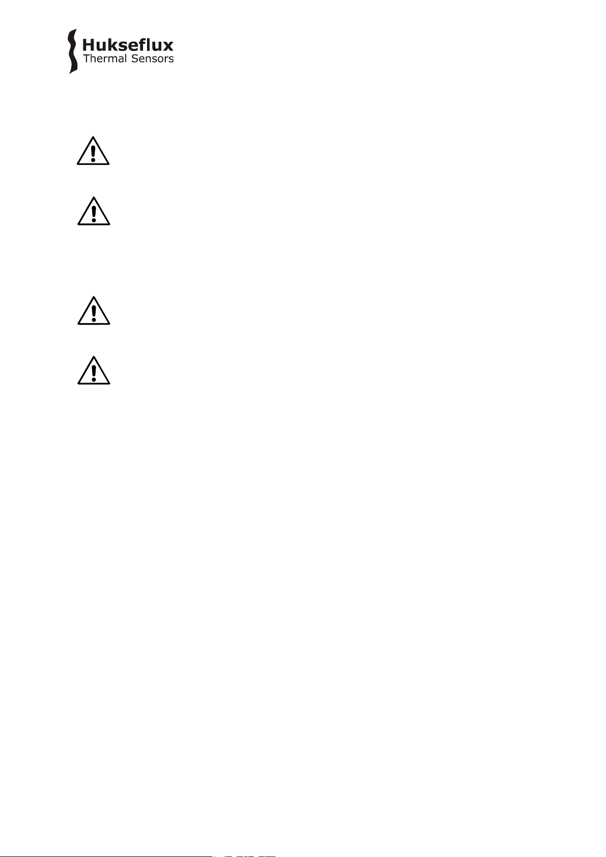
Figure 5.2.1 TCOM01 on its tripod
The TCOMSYS01 comes with a power adapter. Plug the adapter into your power outlet
and connect the Bulgin connector of the power supply to the ‘12VDC’ connector on the
MCU. Ensure both cables between the TCOM01 and the MCU are connected.
Turn the system [ON] by pressing the grey ‘Power’ button on the MCU. The red LED
should light up.
The system will start collecting data immediately. TCOMSYS01 will measure and collect
data as long as power is provided to the system, even without an active connection to
the interface.
Page 23

TCOMSY S 01 manu a l v190 2 23/47
5.3 Software installation
The TCOMSYS01 is operated using a web-based browser, which is pre-loaded on the SD
card. This chapter explains how to get access to the interface. For more setup options,
refer to the appendix on advanced settings.
To connect to the interface, you have two options:
5.3.1 Direct Ethernet connection
Connect an Ethernet cable to the ‘RJ45’ connector on the MCU and plug this into your
Local Area Network (LAN). You may use the supplied Bulgin connector for a more secure
and weatherproof connector.
The system will be assigned an IP address automatically.
Open your web browser and enter ‘TCOMSYS01/’ in your address bar.
If your network does not allow for systems to assign their own name, you need to
manually enter the IP address of the TCOMSYS01.
To find the IP address, you can use the Campbell Scientific LoggerLink app, available
from https://www.campbellsci.com/loggerlink.
In the LoggerLink app, you can search for dataloggers on your network using the search
function under ‘TCP settings’.
Figure 5.3.1.1 Using the LoggerLink app to find TCOMSYS01’s IP address
Page 24

TCOMSY S 01 manu a l v190 2 24/47
Alternatively, you can search for the TCOMSYS01 using the Campbell Scientific Device
Configuration Utility, available from https://www.campbellsci.com/devconfig.
In the Device Configuration Utility, select ‘CR1000X Series’ under the ‘Datalogger’
options, make sure to select ‘IP’ and click the ‘looking glass’ next to the ‘Server Address’
field.
When you have found the IP address of the TCOMSYS01, open your web browser and
type the IP address in your address bar.
Figure 5.3.1.2 Using the Device Configuration Utility to find TCOMSYS01’s IP address
Page 25

TCOMSY S 01 manu a l v190 2 25/47
5.3.2 Ethernet over USB connection
Plug the USB cable into the ‘USB’ connector on the MCU and connect to your PC. The
drivers should be installed automatically. Once this process is complete, open your web
browser and enter the IP address for the USB port into your address bar. By default, this
is 192.168.66.1.
If the drivers are not automatically installed, install the USB drivers using the Campbell
Scientific Device Configuration Utility available from
https://www.campbellsci.com/devconfig.
Under ‘Datalogger’, select ‘CR1000X series’ and choose ‘Install USB Driver’.
Figure 5.3.1.2 Using the Device Configuration Utility when drivers are not installed
automatically
5.4 Set the TCOMSYS01 clock
5.4.1 Via Ethernet connection
Connect to the TCOMSYS01 using the Campbell Scientific LoggerLink app.
In the ‘Status’ menu, scroll down to the bottom and choose ‘Set Clock’.
You can choose to set the clock to the server time, or set a time manually.
Page 26

TCOMSY S 01 manu a l v190 2 26/47
Figure 5.4.1.1 Using the LoggerLink app when setting the TCOMSYS01 clock over Ethernet
5.4.2 Via Ethernet over USB connection
Connect to the TCOMSYS01 using the Campbell Scientific Device Configuration Utility. Under
‘Logger Control’, choose ‘Set Clock’ to set the TCOMSYS01 time to the reference time.
Figure 5.4.2.1 Using the Device Configuration Utility when setting the TCOMSYS01 clock
via Ethernet over USB
Page 27
TCOMSY S 01 manu a l v190 2 27/47
6 Working with the system
The user should be familiar with the warning statements indicated on page 2 of this
manual.
6.1 Basic functionality
The ‘Main Screen’ of the interface shows a live display of the TCOMSYS01 measurement.
It gives live numerical data of the TCOM01 temperature, the measured heat fluxes in all
five directions, the environmental parameters and heater power used to maintain the
TCOM01 temperature.
Also, a graph is shown with data of the last 10 minutes.
It is possible to zoom in on the graph by drawing a rectangle with your mouse. Right
click on the interface to open a menu with options to ‘Show All Data’ or ‘Restore’ to the
original view.
In the top right corner, the TCOMSYS01 date and time are shown.
Figure 6.1.1 TCOMSYS01 main screen shows live data, and a graph of the last 10
minutes.
Page 28

TCOMSY S 01 manu a l v190 2 28/47
In the main screen, it is possible to change the TCOM01 temperature setting by changing
‘Target temperature’. It is possible to turn the heater ON or OFF by pressing the ‘heater’
button. The red bar will light up if the heater is turned ON.
Figure 6.1.2 In the TCOM01 parameters field, it is possible to change the TCOM01
target temperature and turn the heater ON and OFF
The first time you want to change something in the interface, the system will ask for a
user name and password. These can be found on the product certificate. The default user
name is TCOMSYS01, the default password is the serial number of the system.
Check whether all variables make sense:
Table 6.1.1 expected values for measured variables
MEASURAND
EXPECTED VALUE
TCOM01 body temperature
equal to target temperature, within ± 0.2 °C
stable within ± 0.2 °C
Heat fluxes
-50 to -150 W/m² in standard conditions
influenced by convective and radiative sources
noise level depends on activity
Air temperature
equal to room temperature
Relative humidity
0 to 100 %
Heater power
0 to 40 W
Duty cycle
0 to 100 %
Page 29

TCOMSY S 01 manu a l v190 2 29/47
6.2 Data retrieval
To retrieve data from TCOMSYS01, you can work from the ‘Browse Data’ tab of the
interface.
Data of the TCOMSYS01 is stored in several tables, the relevant measurement data is in
the TCOMSYS01Data table.
To view the last record, click on the ‘TCOMSYS01Data’ link.
To retrieve data, click ‘custom’ next to ‘TCOMSYS01Data’.
This will open a custom data query window. There are several options for resulting data
format and data query mode, see Table 6.2.1.
For further analysis, choosing a TOA5 data format is usually most convenient.
Figure 6.2.1 Clicking ‘custom’ in the Data Browser allows for a custom data query. The
image on the right depicts an example of data retrieval from the TCOMSYS01.These
settings will download a comma separated file with data from one specific day.
Page 30

TCOMSY S 01 manu a l v190 2 30/47
Table 6.2.1 data retrieval definition and settings
Stored measurement definition
operator name, comment, averages of heater power,
heat fluxes, TCOM01 body temperature,
heating flag, duty cycle of pulse width modulation,
ambient air temperature, relative humidity,
datalogger supply voltage
(Averaging period is adjustable by user. By doing so
the data storage interval is altered.)
Resulting data format options
html (hypertext markup language)
json (java script object notation)
toa5 (table output ascii version 5)
tob1 (table out binary version 1)
xml (extensible markup language)
Data query mode options
most-recent (most recent number of records)
since-time (all data since a certain time)
since-record (all data since a certain record number)
data-range (all data within a certain time interval)
backfill (most recent amount of seconds)
Page 31

TCOMSY S 01 manu a l v190 2 31/47
6.3 Example experiments
To become familiar with TCOMSYS01, we recommend the following tests.
Perform all tests in a stable indoor condition. Before every test, make sure the TCOM01
is fully stabilised at its default temperature setting of 33 °C.
6.3.1 Change the TCOM01 temperature setting
By default, the TCOM01 temperature is stabilised at 33 °C.
Change this setting to 37 °C by changing the value of the ‘Target temperature’ to 37 °C.
TCOMSYS01 will increase the heating power to reach the new requested value, and then
stabilise around a higher heater power. The radiative and convective heat losses to the
environment will also increase, as the temperature difference between the TCOM01 and
the environment becomes larger.
This is also expected from a conservation of energy standpoint. When the TCOM01
temperature is constant, all the energy that is dissipated within the TCOM01 is lost to
environment.
Figure 6.3.1.1 TCOMSYS01 experiment: increase the target temperature. Heater power
stabilises at a higher value, heat losses to the environment increase
Page 32

TCOMSY S 01 manu a l v190 2 32/47
6.3.2 Touch the different sides of TCOM01
Touch the black adhesive foils on the five different sides with your bare hand. The
corresponding heat flux sensor should react. After releasing the sensor, the heat flux
signal should slowly return to the original value.
Your hand is colder than TCOM01; the TCOM01 side you are touching will lose more heat
by conduction.
Also, the power required to maintain the TCOM01 temperature will increase to
compensate for the increased heat loss.
Figure 6.3.2.1 TCOMSYS01 experiment: touch the TCOM01 with your hand. First, the
front of the TCOM01 is touched for 30 seconds. 3 minutes later, the left side of the
TCOM01 is touched for 30 seconds. Heat loss to the touched side of the TCOM01 is
temporarily increased. The power required for stabilisation is slightly increased to
compensate.
Page 33

TCOMSY S 01 manu a l v190 2 33/47
6.3.3 Blow ambient air on one side of TCOM01
Blow ambient air on one side of TCOM01 using a fan. The heat flux sensors should react.
The heat flux sensor on the opposite side of the TCOM01 should show the least reaction.
When you turn the fan off, the heat flux signals should slowly return to their original
values.
TCOM01 is warmer than the environment. By increasing the air speed, you increase
convective heat losses from the TCOM01 to the environment.
Also, the power required to maintain the TCOM01 temperature will increase.
Figure 6.3.3.1 TCOMSYS01 experiment: blow air on the TCOM01 with a fan. For 4
minutes, air is blown on the back of the TCOM01 with a small fan. All heat losses
increases, the front of the TCOM01 is least affected. The power required to maintain the
TCOM01 temperature increases as well. Afterwards, everything returns to its original
values.
Page 34

TCOMSY S 01 manu a l v190 2 34/47
6.3.4 Expose one side of TCOM01 to a strong light source
Shine on one side of TCOM01 with a lamp. The heat flux sensor should react. Turn off the
lamp. The heat flux sensor should slowly return to its original value.
A lamp is source of radiative heat (both in the shortwave and the longwave spectrum).
The black adhesive foil on the exposed heat flux sensor absorbs this heat and it flows
into the TCOM01 (a positive heat flux).
The power required to maintain the TCOM01 temperature will decrease.
Figure 6.3.4.1 TCOMSYS01 experiment: shine on one side of the TCOM01 with a lamp.
A strong lamp shines on the right side of the TCOM01 for 2.5 minutes. This radiation
from the lamp is absorbed by the black foils, creating a radiative asymmetry. The sides
of the TCOM01 that are not exposed are not affected.
Page 35

TCOMSY S 01 manu a l v190 2 35/47
7 Maintenance and trouble shooting
To check the status of the datalogger, look at the ‘Datalogger Status’ tab of the interface.
For general maintenance on the system, like changing the station time, we recommend
to use the Campbell Scientific LoggerLink app, available from
https://www.campbellsci.com/loggerlink.
Alternatively, you can use Campbell Scientific Device Configuration Utility, available from
https://www.campbellsci.com/devconfig.
7.1 Recommended maintenance and quality assurance
TCOMSYS01 measures reliably at a low level of maintenance. Unreliable measurement
results are detected by scientific judgement, for example by looking for unreasonably
large or small measured values. The preferred way to obtain a reliable measurement is a
regular critical review of the measured data, preferably checking against other
measurements.
Table 7.1.1 Recommended maintenance of TCOMSYS01
MINIMUM RECOMMENDED TCOMSYS01 MAINTENANCE
INTERVAL
SUBJECT
ACTION
1
every
measurement
data analysis
Critically review the data.
Look for any patterns and events that deviate from what is
normal or expected.
Inspect cable quality, inspect mounting.
2
2 years
system check
Perform a full functional check of the system.
Preferably, send the system back to the manufacturer for this
check.
3 lifetime
assessment
Judge if the instrument will be reliable for another 2 years, or
if it should be replaced.
4
> 3 years
possible
battery
replacement
The internal battery in the MCU is rated for a 3 year life with
no external power source.
If the battery is exhausted, contact the factory for instructions.
Page 36

TCOMSY S 01 manu a l v190 2 36/47
7.2 Trouble shooting
Table 7.2.1 Trouble shooting for TCOMSYS01 (continued on next page)
General
Inspect the sensors and MCU for any damage. Check the condition of the
cables.
Check if the datalogger program is running.
Check the CR1000X Station Status for error messages (in the ‘Datalogger
Status’ tab of the interface.
The FHF01 sensors do
not give any signal
Check if the sensors react to heat: Expose the sensor to heat, for
instance touching it with your hand. Touching the black absorber should
show a response on the heat flux sensor.
Disconnect cable 1 from the MCU. Check the electrical resistance of the
sensor between the connector pins 1 and 6, 2 and 6, 3 and 6, 4 and 6,
and 5 and 6. Use a multimeter at the 100 Ω range. Measure the sensor
resistance first with one polarity, then reverse the polarity. Take the
average value.
Measured resistance should be within the sensor resistance range of 50
to 100 Ω.
Infinite resistance indicates a broken circuit; zero or a low resistance
indicates a short circuit.
The heater power does
not give any signal
Check the status of the ‘Heater’ button on the ‘Main Screen’. This must
be highlighted for the heater to work.
Update the measurement of the heater current by pressing the ‘Measure
heater current’ button on the ‘Advanced’ of the interface.
Disconnect cable 2 from the MCU. Check the electrical resistance of the
heater between the connector pins 1 and 3 (or alternatively 2 and 4).
Use multimeter at the 10 Ω range. Measure the heater resistance first
with one polarity, then reverse the polarity. Take the average value.
Measured resistance should be the typical heater resistance of 4 Ω.
Infinite resistance indicates a broken circuit; zero or a low resistance
indicates a short circuit. The thermal fuse may be molten.
The body temperature
does not give any
signal
Disconnect cable 1 from the MCU. Check the electrical resistance of the
10 kΩ thermistor between the connector pins 7 and 8. Use multimeter at
the 100 kΩ range. Measure the 10 kΩ thermistor resistance first with one
polarity, then reverse the polarity. Take the average value.
Measured resistance should be the typical 10 kΩ thermistor resistance of
10 kΩ.
Infinite resistance indicates a broken circuit; zero or a low resistance
indicates a short circuit.
The ambient air
temperature and
relative humidity do not
give any signal
Inspect the humidity module on the MCU for any damage.
If problems remain, contact the factory for instructions.
There are doubts about
the MCU measurement
Compare measurement results to those with a calibrated multimeter.
Short-circuit the input using a 10 Ω resistor. The heat flux signal should
be 0 W/m2, the temperature signal should reach 325 °C.
Page 37

TCOMSY S 01 manu a l v190 2 37/47
Table 7.2.1 Trouble shooting for TCOMSYS01 (started on previous page)
The sensor signals are
unrealistically high or
low
Check the cable condition looking for cable breaks.
Check the data acquisition by applying a 1 x 10⁻⁶ V source to it in the
1 x 10⁻⁶ V range. Look at the measurement result. Check if it is as
expected.
Check the data acquisition by short circuiting the data acquisition input
with a 10 Ω resistor. Look at the output.
The sensor signals
show unexpected
variations
Check the presence of strong sources of electromagnetic radiation (radar,
radio).
Check the condition of the sensor cable.
Check if the cable is not moving during the measurement.
Page 38

TCOMSY S 01 manu a l v190 2 38/47
Page 39

TCOMSY S 01 manu a l v190 2 39/47
8 Appendices
8.1 Advanced settings
On the ‘Advanced’ tab of the interface, it is possible to fine tune the TCOMSYS01.
NOTE: changing these parameters may cause the TCOMSYS01 measurement to become
unstable. The recommended settings are entered as default values.
Table 8.1.1 TCOMSYS01 advanced settings (continued on next page)
Maximum temperature
Software limit on the maximum temperature of the TCOM01 in [°C].
Above this temperature, duty cycle will be set to 0 % automatically.
NOTE: TCOM01 has a temperature fuse that limits the temperature to
60 °C. Do not enter a maximum temperature above 60 °C.
Default value: 55 °C
Heater calibration
interval
Interval at which the heater current draw is measured. Every heater
calibration interval, the duty cycle is set to 100 % for 10 scans and the
heater current draw is measured and updated
Default value: 360 min
Average count
Number of scans that are used to determine the averages of heater
power, heat fluxes, TCOM01 body temperature,
The time over which the measurements are averages is determined
both by the average count and the scan interval
Default value: 40 scans
The interval at which data is written to the “TcomSysData” table is the
<number of scans> x 1500 ms. Default 1 per minute.
P gain factor
The proportional gain of the PID controller
Default value: 6.0
I gain factor
The integral gain of the PID controller
Default value: 0.2
D gain factor
The differential gain of the PID controller
Default value: 0.2
Username
Field to enter an operator name. This name will be written to the
‘TcomSysData’ table.
Field is limited to 40 characters
Comment
Field to enter a comment on your measurement. This comment will be
written to the ‘TcomSysData’ table.
Field is limited to 64 characters
Page 40

TCOMSY S 01 manu a l v190 2 40/47
Table 8.1.2 TCOMSYS01 advanced buttons
Apply and Reset
Apply any changes in the Constants table.
Pressing this button will force a restart of the TCOMSYS01
Measure heater current
Force a measurement of the heater current
Duty cycle will be set to 100 % for the specified ‘Heater calibration
time’ and the heater current value will be updated.
Table 8.1.3 TCOMSYS01 advanced read only parameters
Logger temperature
CR1000X panel temperature
Supply voltage
CR1000X supply voltage
Page 41

TCOMSY S 01 manu a l v190 2 41/47
8.2 Ordering the TCOM01 sensor only
The TCOM01 thermal comfort sensor is also available as a “sensor only”.
The configuration includes the mannequin with 5 x heat flux, 1 x temperature, 1 x
heater, 2 x cable, 2 x chassis connector and 1 x tripod. The user then must combine it
with his own measurement and control unit.
Arriving at the customer, the delivery of TCOM01 should include:
• 1 x HPRC 2300 carrying case
• 1 x TCOM01 thermal comfort sensor
• 1 x 5 pin PHOENIX CONTACT cable, 1.5 m
• 1 x 8 pin PHOENIX CONTACT cable, 1.5 m
• 1 x Manfrotto PIXI EVO 2 tripod
• 1 x Binder M12-A chassis connector 5 pin
• 1 x Binder M12-A chassis connector 8 pin
• 1 x product certificate
Figure 8.2.1 TCOM01 as “sensor only“, supplied with two cables.
Page 42

TCOMSY S 01 manu a l v190 2 42/47
To build your own thermal comfort measuring system,
1) Measure the resistance of the 10 kΩ thermistor and convert this to temperature.
To convert the resistance in Ω to temperature in °C, use the Steinhart-Hart equation.
with R
thermistor
the thermistor resistance in Ω, T the temperature in °C, α, β and γ the
Steinhart-Hart coefficients
α = 1.1226 x 10
-3
β = 2.3517 x 10⁻⁴
γ = 8.3908 x 10
-8
2) Measure the voltage output of the 5 heat flux sensors and convert this to heat flux.
To convert the voltage output to heat flux, use
with U the voltage output in V, S the sensitivity of the heat flux sensor in V/(W/m²) and
Φ the heat flux in W/m².
The sensitivity of the heat flux sensors can be found on the product certificate
3) Supply power to the heater.
The heater is specified for a maximum power of 40 W and has a nominal resistance of
3.6 Ω. The individual heater resistance can be found on the product certificate. When
calculating heater power, account for a cable resistance of 0.6 Ω.
Do not use more than 12 VDC to power the heater.
Control the heater power to maintain a stable TCOM01 temperature, for example using a
PID controller.
Measure the heater power, by measuring the voltage drop over the heater, the current
draw of the heater, or both.
(Formula 8.2.2)
(Formula 8.2.1)
Page 43

TCOMSY S 01 manu a l v190 2 43/47
Colour coding of the chassis connectors and an example of a measurement circuit are
shown below.
Table 8.2.1 connections Cable 1
Table 8.2.2 connections Cable 2
PIN
WIRE
1
white
heat flux top [+]
2
brown
heat flux right [+]
3
green
heat flux front [+]
4
yellow
heat flux left [+]
5
grey
heat flux back [+]
6
pink
heat flux (all) [−]
7
blue
10 kΩ thermistor [+]
8
red
10 kΩ thermistor [−]
PIN
WIRE
1
brown
heater [+]
2
white
heater [+]
3
blue
heater [−]
4
black
heater [−]
5
grey
not connected
Figure 8.2.1 Example of a measurement circuit used to build a thermal comfort
measuring system with a TCOM01 thermal comfort sensor.
Page 44

TCOMSY S 01 manu a l v190 2 44/47
8.3 EU declaration of conformity TCOMSYS01
We, Hukseflux Thermal Sensors B.V.
Delftechpark 31
2628 XJ Delft
The Netherlands
in accordance with the requirements of the following directive:
2006/95/EG The Low Voltage Directive
2011/65/EU The Restriction of Hazardous Substances Directive
2014/30/EU The Electromagnetic Compatibility Directive
hereby declare under our sole responsibility that:
Product model: TCOMSYS01
Product type: Thermal comfort measuring system
has been designed to comply and is in conformity with the relevant sections and
applicable requirements of the following standards:
Emission: IEC/EN 61000-6-1, Class B, RF emission requirements (toughest), IEC
CISPR11 and EN 55011 Class B requirements
Immunity: IEC/EN 61000-6-2 (toughest) and IEC 61326 requirement
Report: “Hukseflux Tcomsys01_b.pdf”, 21 November 2018
Eric HOEKSEMA
Director
Delft
November 23, 2018
Page 45

TCOMSY S 01 manu a l v190 2 45/47
8.4 EU declaration of conformity TCOM01
We, Hukseflux Thermal Sensors B.V.
Delftechpark 31
2628 XJ Delft
The Netherlands
in accordance with the requirements of the following directive:
2011/65/EU The Restriction of Hazardous Substances Directive
2014/30/EU The Electromagnetic Compatibility Directive
hereby declare under our sole responsibility that:
Product model: TCOM01
Product type: Thermal comfort sensor
has been designed to comply and is in conformity with the relevant sections and
applicable requirements of the following standards:
Emission: IEC/EN 61000-6-1, Class B, RF emission requirements (toughest), IEC
CISPR11 and EN 55011 Class B requirements
Immunity: IEC/EN 61000-6-2 (toughest) and IEC 61326 requirement
Report: “Hukseflux Tcomsys01_b.pdf”, 21 November 2018
NOTE: TCOM01 has been tested in a specific system configuration
Eric HOEKSEMA
Director
Delft
November 23, 2018
Page 46

Page 47

© 2019, Hukseflux Thermal Sensors B.V.
www.hukseflux.com
Hukseflux Thermal Sensors B.V. reserves the right to change specifications without notice.
 Loading...