

Page 1
Copyright by Hukseflux | manual v1627 | www.huksefluxusa.com | info@huksefluxusa.com
USER MANUAL STP01
Soil temperature profile sensor with self-test
Page 2

STP 01 manu al v 162 7 2/ 31
Warning statements
Putting more than 2 Volt across the sensor wiring
can lead to permanent damage to the sensor.
Putting more than 15 Volt across the heater wiring
can lead to permanent damage to the heater.
Do not use “open circuit detection” when measuring
the thermocouple sensor output.
Page 3

STP 01 manu al v 162 7 3/ 31
Contents
Warning statements 2
Contents 3
List of symbols 4
Introduction 5
1 Ordering and checking at delivery 9
1.1 Ordering STP01 9
1.2 Included items 9
1.3 Quick instrument check 9
2 Instrument principle and theory 10
2.1 General soil temperature measurement 10
2.2 STP01 soil temperature measurement 10
2.3 STP01 on-line self-test 11
2.4 Optional thermal conductivity measurement 11
2.5 Conformity testing and traceability 12
2.6 Programming 13
3 Specifications of STP01 14
3.1 Dimensions of STP01 17
4 Standards and recommended practices for use 18
5 Installation of STP01 19
5.1 Site selection and installation 19
5.2 Electrical connection 20
5.3 STP01 diagnostics 22
5.4 Requirements for data acquisition / amplification 23
6 Making a dependable measurement 24
6.1 Uncertainty evaluation 24
6.2 Contributions to the uncertainty budget 24
7 Maintenance and trouble shooting 26
7.1 Recommended maintenance and quality assurance 26
7.2 Trouble shooting 27
8 Appendices 29
8.1 Appendix on cable extension / replacement 29
8.2 EU declaration of conformity 30
Page 4

STP 01 manu al v 162 7 4/ 31
List of symbols
Quantities Symbol Unit
Temperature T °C
Temperature difference ΔT °C, K
Thermal conductivity λ W/(m∙K)
Voltage output U V
Voltage output as a function of heating time U (t) V
Voltage output difference ΔU V
Sensitivity S V/K
Heating power per meter Q W/m
Heater length L m
Time constant τ s
Time t s
Resistance R Ω
Depth of installation x m
Distance from the heater r m
Subscripts
property of a sensor sensor
property of the reference temperature Pt100 reference
property at the (soil) surface surface
property of the surrounding soil soil
property of the heater heater
Page 5

STP 01 manu al v 162 7 5/ 31
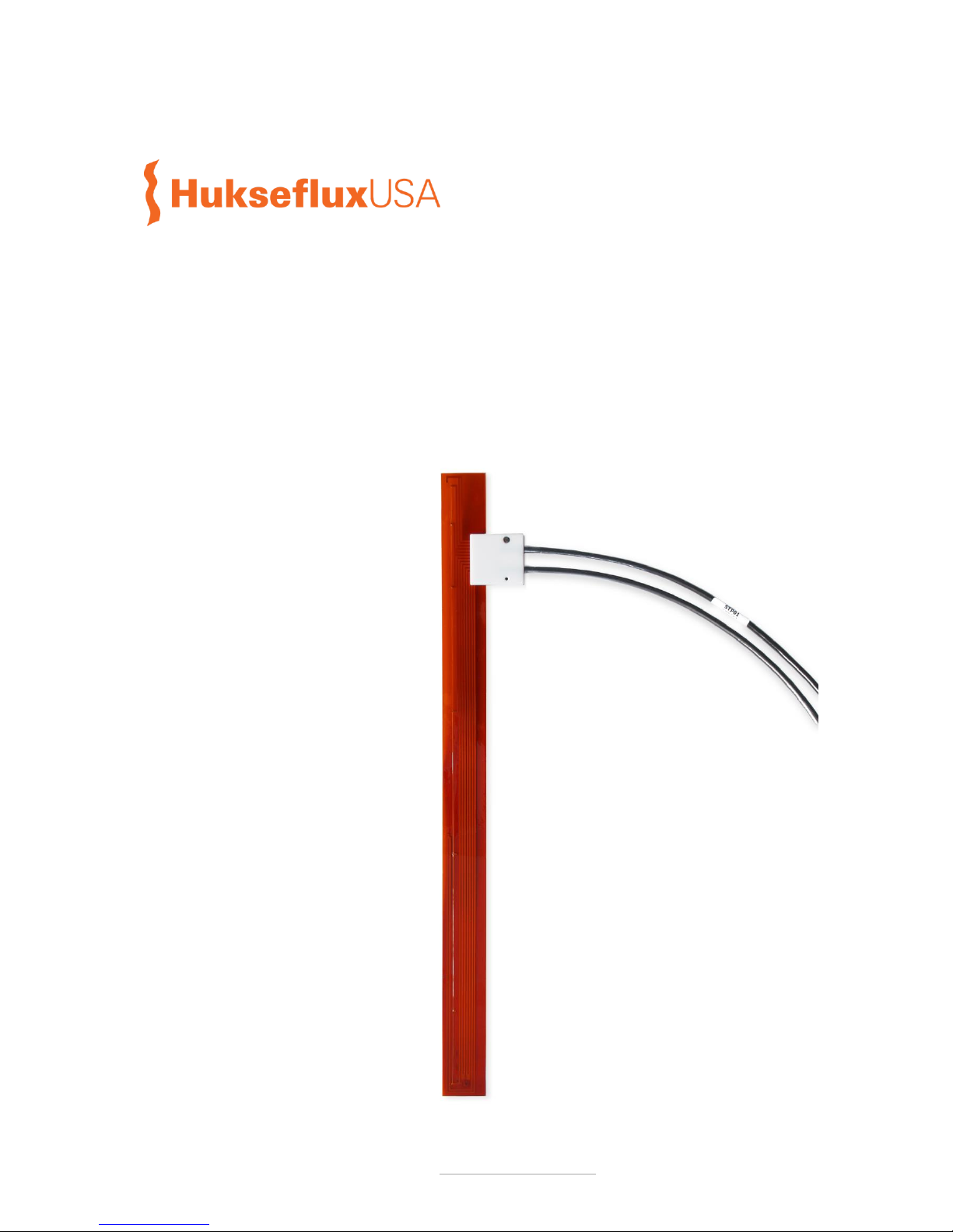
Introduction
STP01 accurately measures the temperature profile of the soil at 5 depths close to its
surface. It is used for scientific grade surface energy balance measurements. The sensor
is buried and usually cannot be taken to the laboratory for calibration. The on-line selftest using the incorporated heating wire offers a solution to verify STP01’s measurement
stability.
STP01 soil temperature profile sensor offers an accurate temperature difference
measurement at five measurement locations at 0.02, 0.05, 0.1, 0.2 and 0.5 m below the
soil surface. It also has a well specified and fixed distance between the measurement
locations.
STP01 contains 5 matched thermocouples, at locations A to E, and one reference
temperature sensor (Pt100 type) at location E at 0.5 m depth (see figure 0.2). By having
the reference temperature measurement in the sensor and only measuring differential
thermocouple voltages (relative to the reference at 0.5 m), the uncertainty of the
temperature difference measurement is very low: ± 0.02 °C is attainable. Simple copperconductor signal wire is used in STP01’s cable. As an extra, a heating wire is incorporated
in STP01. Analysis of the temperature change during the heating interval serves as a
self-test.
Soil temperature sensors are preferably left in the soil for as long as possible, so that the
soil properties become representative of natural conditions. Using self-testing, the user
no longer needs to take sensors to the laboratory to verify their stable performance.
The result is a much improved accuracy & quality assurance of the measurement relative
to measurements with conventional sensor types.
Typically every 24 hours, the STP01 heater is switched on to perform a self-test.
When activating the heater for a self-test, this will lead to a local increase in temperature
at the sensors at 0.02, 0.05, 0.1 and 0.2 m depth. The STP01 stability is monitored by
analysis of yearly patterns of this step-response.
The step response of the temperature during the self-test can be used to measure the
soil thermal conductivity at 3 depths; 0.05, 0.1 and 0.2 m. For more background on this
measurement method, see the manual of model TP02 thermal needle. The possibility to
perform this measurement is an experimental option, with an unspecified measurement
accuracy.
STP01 is used for high accuracy, scientific grade measurement of the soil energy
balance, with a high level of data quality assurance. Measurements with STP01 are often
combined with soil thermal conductivity and volumic heat capacity measurements with
sensor model TP01 and measurements with heat flux sensor model HFP01SC.
Page 6

STP 01 manu al v 162 7 6/ 31
STP01 advantages are:
high accuracy, scientific measurement of soil energy balance, with a high level of data
quality assurance
high accuracy K/m temperature gradient measurement by accurate positioning of the
thermocouple joints (± 0.001 m), and accurate temperature difference measurement
(± 0.02 K)
high accuracy and stability of the relative distance between sensors (± 0.0005 m)
thin, 0.6 x 10
-3
m thickness, construction which leaves the soil structure intact
simple copper-core signal wire; no special connectors needed
self-test saves servicing time
Sensors made by Hukseflux are designed for compatibility with the most commonly used
datalogger models. For many models we have example programs and wiring diagrams
available.
Requirements for data acquisition and control are:
for temperature measurement: four millivolt measurements, one Pt100 measurement
for the optional self-test: one heater voltage measurement
for the optional self-test: one relay with 12 VDC nominal output, switching the heater
on and off
Equipped with heavy duty cabling, and potted so that moisture does not penetrate the
sensor, STP01 has proven to be very robust and stable. It survives long-term installation
in soils. For ease of installation with a minimum of disturbance of the local soil, Hukseflux
offers IT01 insertion tool.
Figure 0.1 STP01. Standard cable length is 5 m.
Page 7
STP 01 manu al v 162 7 7/ 31
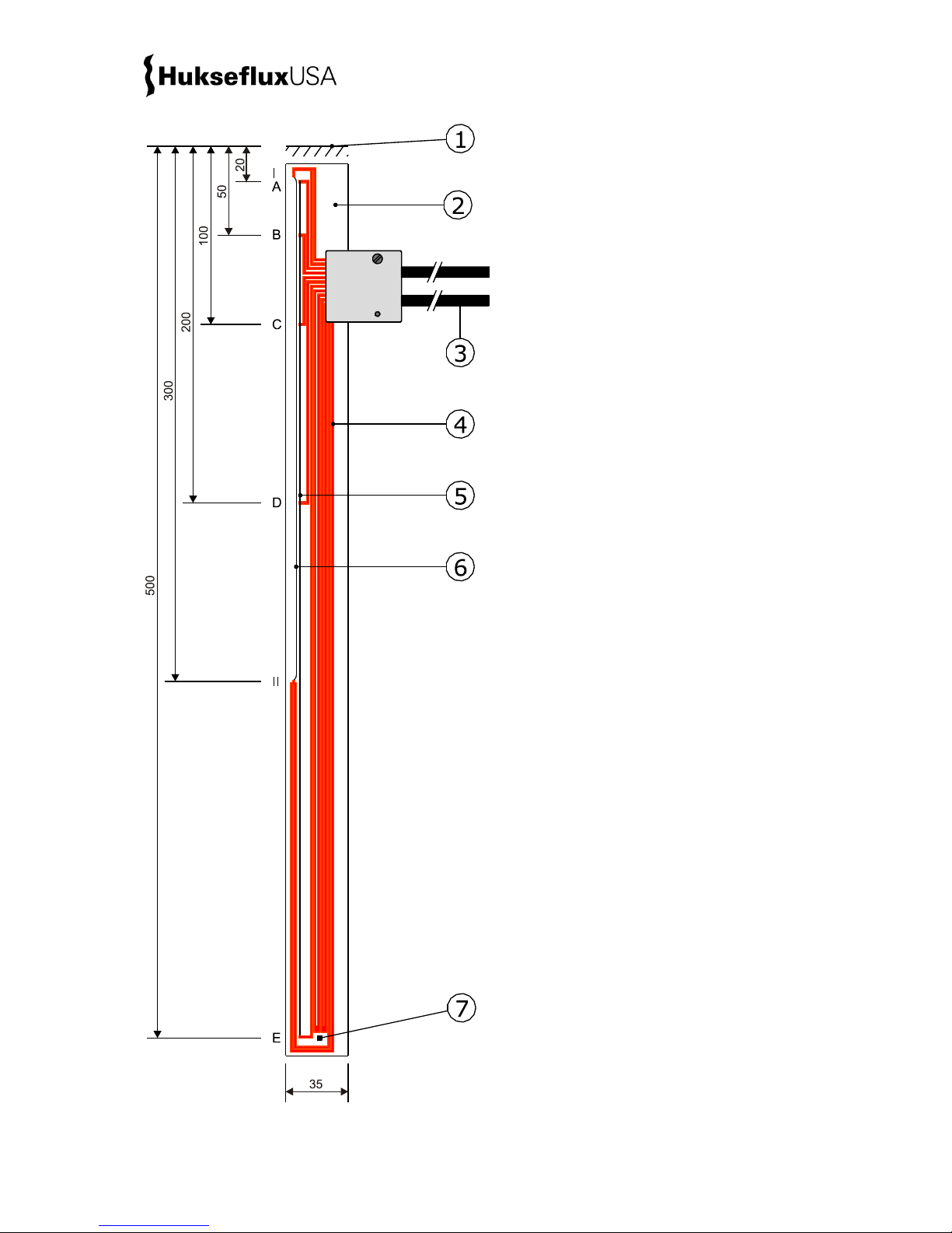
Figure 0.2 STP01 layout and dimensions
1 soil surface
2 sensor foil (0.6 x 10⁻³ m thickness, 2.5 x 10⁻³
m at Pt 100)
3 2 x cable 5 m (see options)
4 copper leads
5 T type thermocouple wire
6 CuNi heater wire
7 Pt100 reference temperature sensor (4-wire
connection)
I and II: connection points of the heating wire
(4-wire connection)
A, B, C, D and E: thermocouple type T joints
Dimensions in x 10-3 m
Page 8

STP 01 manu al v 162 7 8/ 31
Options are:
longer cable (2 x), in multiples of 5 m, cable lengths above 20 m in multiples of 10 m
insertion tool IT01
Figure 0.3 IT01 insertion tool is hammered down into the soil. After retracting it leaves
a slit in which STP01 may be inserted.
See also:
model TP01 soil thermal properties sensor
soil heat flux sensors HFP01 and HFP01SC
view our complete product range of surface energy flux measurement products
view our range of pyranometers and net-radiometers
Page 9

STP 01 manu al v 162 7 9/ 31
1 Ordering and checking at delivery
1.1 Ordering STP01
The standard configuration of STP01 is with 2 x 5 metres cable.
Common options are:
longer cable in multiples of 5 m, cable lengths above 20 m in multiples of 10 m.
specify total cable length.
insertion tool IT01
1.2 Included items
Arriving at the customer, the delivery should include:
thermal properties sensor STP01
cable of the length as ordered
product certificate matching the instrument serial number
1.3 Quick instrument check
A quick test of the instrument can be done by connecting it to a multimeter.
1. Check the electrical resistance of the sensor and heater according to the tables in
paragraph 5.3. Use a multimeter at the 50 and 500 Ω range. The typical resistance of the
wiring is 0.4 Ω/m (added value of 2 wires). Infinite resistance indicates a broken circuit;
zero or a lower than 1 Ω resistance indicates a short circuit.
2. Check if the thermocouple sensors react to heat: put the multimeter at its most
sensitive range of DC voltage measurement, typically the 100 x 10-3 VDC range or lower.
Measure between the thermocouple common and the other thermocouple joints. Look at
the reaction when you heat one of the joints.
3. Inspect the sensor foil for any damage.
4. Check the sensor serial number on the cable labels (one at sensor end, one at cable
end of both cables) against the product certificate provided with the sensor.
Page 10

STP 01 manu al v 162 7 10/31
2 Instrument principle and theory
STP01 accurately measures the temperature profile of the soil at 5 depths close to its
surface. A requirement for an accurate measurement is good thermal contact between
soil and sensor. The sensor is buried and usually cannot be taken to the laboratory for
calibration. The on-line self-test using the incorporated heating wire offers a solution to
verify STP01’s measurement stability. The user must incorporate STP01 in his own
measurement and control system. For soil temperature measurement this system should
perform 4 x voltage, and 1 x Pt100 readout. For the self-test you need power supply
switching, and 1 x voltage readout.
Relevant features of TP01 are:
robustness, including a strong cable (essential for permanently installed sensors)
IP protection class: IP67 (essential for outdoor application)
low electrical resistance (low pickup of electrical noise)
2.1 General soil temperature measurement
Usually temperature gradients in the soil are made using separate sensors.
Shortcomings of this method are:
temperature gradients are calculated by taking the difference between inaccurate
measurements. The end result will have a large uncertainty
the relative position is not accurately determined
the sensor construction is often heavy, and conducting a significant amount of heat
Soil temperature and soil thermal properties vary slowly. Usually the data sampling is
done with a 60 s interval and 10 minute averages are stored. You may choose to vary
the data storage interval with depth.
2.2 STP01 soil temperature measurement
STP01 overcomes the traditional shortcomings:
STP01 uses a string of thermocouples type T sharing one and the same CuNi wire and
the same Cu wire (made from the same sheet). We claim that the thermocouples are
“matched”, i.e. have the same properties. The relative accuracy of such matched
thermocouples is better than 0.05 °C.
Determined by the manufacturing process, the relative position of the thermocouple
joints is accurate within ± 0.001 m.
The construction of STP01 consists of plastic foil and relatively thin conductors.
Page 11

STP 01 manu al v 162 7 11/31
A thermocouple type T has an analogue voltage output and a sensitivity of around 40 x
10-6 V/K temperature difference between its two joints. The sensitivity is not a constant
but is a function of T and ΔT.
U = S (T, ΔT) · ΔT (Formula 2.2.1)
In order to measure absolute temperatures at the joints at depth x, the temperature at
one reference joint must be measured. The Pt100 located at 0.5 m depth serves as
“reference temperature”. The thermocouple joint at 0.5 m serves as “reference junction”.
A Pt100 is a standardised type temperature sensitive resistor. It is made of platinum (the
element Pt) and has an electrical resistance of 100 Ω at 0 °C.
T (x) = T
reference
+ U / S (T, ΔT) (Formula 2.2.2)
In commonly used dataloggers it is possible to define the reference temperature T
reference
and the thermocouple type. The datalogger internally calculates absolute temperatures T
(x) using an internal lookup instruction.
2.3 STP01 on-line self-test
The purpose of the self-test is to judge if
the temperature sensors still work, and if so
if they are in good contact with the soil
Typically every 24 hours, the STP01 heater is switched on for 600 s to perform a selftest. When activating the heater for a self-test, this will lead to a local increase in
temperature at the sensors at 0.02, 0.05, 0.1 and 0.2 m depth. The STP01 stability is
monitored by analysis of yearly patterns of this step-response for every depth, corrected
for the heater power. The heater power is, assuming that the resistance is constant,
expressed as U
heater
2
.
U = S · T/U
heater
2
(Formula 2.3.1)
During the self-test, we recommend storing the measured data using a 1 [s] data
storage interval. The time response for one sensor will vary with the soil thermal
conductivity and with the contact between the sensor and the soil. You may look for
yearly patterns.
2.4 Optional thermal conductivity measurement
The step response of the temperature during the self-test can be used to measure the
soil thermal conductivity at 3 depths; 0.05, 0.1 and 0.2 m. For more background on this
measurement method, see the manual of model TP02 thermal needle. The possibility to
perform this measurement is an experimental option, with an unspecified measurement
Page 12

STP 01 manu al v 162 7 12/31
accuracy. The measurement method is based on the thermal needle method. This
requires both a heating wire and a temperature sensor close to the wire. From the
response to a heating step the thermal conductivity of the soil can be calculated.
The method relies on a unique property of a line source: after a short transient period
the temperature rise, T, only depends on heater power, Q, and medium thermal
conductivity, :
T = (Q / 4 ) (ln t + B) (Formula 2.4.1)
With T in K, Q in W/m, in W/(m·K), t the time in s and B a constant. By measuring the
heater power, and tracing the temperature in time is calculated.
The thermal conductivity can be calculated from two measurements at t1 and t2. For
STP01 both t1 and t2 are higher than 200 s, and typically 200 s apart. T is the
temperature difference between the measurements at time t1 and t2, taking t = 0 at the
moment that the heating starts.
= (Q / 4 T) ln(t2 / t1) (Formula 2.4.2)
2.5 Conformity testing and traceability
During manufacturing STP01 has to pass an acceptance test. In the test we verify if the
properties of the thermocouples, Pt100 and heating wire are within specifications. If the
specified sensors are manufactured as required, we consider them traceable to SI. We
rely on their material specifications which we verify by electrical resistance
measurement.
During use, STP01 is buried and usually cannot be taken to the laboratory for calibration.
The on-line self-test using the incorporated heating wire offers a solution to verify
STP01’s measurement stability.
Page 13

STP 01 manu al v 162 7 13/31
2.6 Programming
In case the user writes his own software program for controlling the measurement with
STP01, the program flow in table 2.6.1 may be used.
Table 2.6.1 a summary of a program for control of the measurement with STP01
initialisation
enter sensor and system
information
serial number, upper and lower acceptance limits for T,
U, thermocouple type T, R
heater
every 1 s
measure
measure T
reference
and T (x) for 4
depths
every 600 s
store
store average values
quality checks
acceptance intervals T (x)
every 24 hr
perform self-test
measure U, U
heat,
t
600 s heating interval
heater on
measure U
measure U
heater
at 600 s
heater off
store data
quality checks
acceptance interval
acceptance interval U
heater
acceptance interval U(0) – U(600)
optional
calculate λ at 3 depths
Page 14

STP 01 manu al v 162 7 14/31
3 Specifications of STP01
STP01 measures the temperature profile of the soil at 5 depths close to its surface. It is
designed for long-term monitoring of soils. Good thermal contact between soil and sensor
is required. The on-line self-test, using the incorporated heating wire, offers a solution
for on-site verification of STP01’s functionality and measurement stability. STP01 can
only be used in combination with a suitable measurement and control system. The
possibility to perform a thermal conductivity measurement at 3 depths is an option with
an unspecified measurement accuracy.
Table 3.1 Specifications of STP01 (continued on next page)
STP01 SPECIFICATIONS
Sensor type
soil temperature profile sensor with self-test
Measurand
temperature at 5 depths from 0 to 0.5 m
Rated operating environment
surrounded by soil
Measurand in SI units
temperature in °C
Temperature sensors
matched thermocouples type T
Reference temperature sensor
Pt100, IEC 751:1983 class B
Measurement depths
0.02, 0.05, 0.1, 0.2 and 0.5 m
On-line functionality testing
self-test using the incorporated heater
Measurement range
-30 to +70 °C
Measurand
temperature difference between reference
temperature at 0.5 m and the other measurement
depths
Measurand in SI units
temperature difference in °C
Measurand
temperature gradient
Measurand in SI units
temperature gradient in K/m
Optional non-traceable measurand
thermal conductivity at 3 depths
Measurand in SI units
thermal conductivity in W/(m·K)
Thermocouple type T sensitivity
40 x 10-6 V/K (nominal)
Measurement function / required
programming
thermocouple type T, using a Pt100 as a reference
temperature measurement
Measurement function / required
programming
for the self-test: see the paragraph on this subject
Optional measurement function/ optional
programming
for thermal conductivity measurement: see the
paragraph on this subject
Required readout and control
1 x Pt100
4 x thermocouple type T voltage using the junction at
0.5 m depth as a reference, input resistance > 106 Ω
Expected voltage output
-2 to 2 x 10⁻³ V (thermocouples)
0 to 15 VDC (heater)
Required uncertainty
10 x 10-6 V at 2 x 10⁻³ V
0.01 V at 12 V
Optional readout and control
only if the self-test is used
heater: 1 x voltage channel which acts as a current
measurement channel using a current sensing resistor
heater: 1 x switchable 12 VDC, 0.06 A
Rated operating temperature range
-30 to +70 °C
Page 15

STP 01 manu al v 162 7 15/31
Table 3.1 Specifications of STP01 (started on previous page, continued on next page)
Sensor foil surface dimensions
(500 x 35) x 10
-3
m
Sensor foil thickness
0.6 x 10⁻³ m
2.5 x 10⁻³ m at Pt100
Connector block dimensions
(40 x 42 x 10) x 10-3 m
Thermocouple sensor resistance range
5 Ω (nominal) + 0.4 Ω/m cable
Standard governing use of the
instrument
not applicable
Standard cable length (2 cables)
5 m (see options)
Wiring
0.15 m wires and shield at cable ends
Cable diameter
2 x 5.5 x 10-3 m
Cable markers
4 x sticker, 1 x at sensor and 1 x cable end, wrapped
around the sensor cables. Both stickers show serial
number and cable 1 / cable 2
IP protection class
IP67
Rated operating relative humidity range
0 to 100 %
Gross weight including 5 m cable
0.7 kg
Net weight including 5 m cable
0.6 kg
Packaging
box of 300 x 210 x 80 mm
HEATER
Heater resistance (nominal)
200 Ω
Heater length
0.28 m
Heater rated power supply
9 to 15 VDC
Heater power supply
12 VDC (nominal)
Power consumption during heating
interval
0.72 W
(heater powered from 12 VDC)
SELF-TEST
Power consumption daily average
0.005 W
(heater powered from 12 VDC, 24 hr interval between
tests)
Interval between self-tests
24 hr
Self-test duration
600 s
INSTALLATION AND USE
Recommended number of sensors
2 per measurement site
Orientation
recommended orientation is with foil surface vertically
oriented (usually this is perpendicular to the soil
surface).
Installation
see recommendations in the product manual
Cable extension
cable extension of STP01 is discouraged: see chapter
on cable extension
Page 16

STP 01 manu al v 162 7 16/31
Table 3.1 Specifications of STP01 (started on previous pages)
CONFORMITY TESTING AND TRACEABILITY
Factory conformity testing
the STP01 functional test compares the electrical
resistance of the produced sensor against the
acceptance interval. This is done for the
thermocouples, Pt100 and heater.
Functional test
STP01 functional test
Calibration traceability
to SI units
Calibration method
by referral to inherent calibration references: type T
thermocouple and Pt 100
Production certificate
included
(confirming result of the functional test)
MEASUREMENT ACCURACY
Uncertainty of the measurement
statements about the overall measurement
uncertainty can only be made on an individual basis.
see the chapter on uncertainty evaluation.
Uncertainty of temperature difference
measurement
1.5 % of measured value plus measurement system
uncertainty in x 10-6 V/40
Uncertainty of reference temperature
measurement
± 0.7 °C plus measurement system uncertainty
Uncertainty of relative position
± 0.001 m
Uncertainty of optional thermal
conductivity measurement
not specified
VERSIONS / OPTIONS
Order code
STP01/cable length in m
Longer cable (2x)
in multiples of 5 m, cable lengths above 20 m in
multiples of 10 m
option code = total cable length
ACCESSORIES
Insertion tool
IT01 insertion tool
Page 17

STP 01 manu al v 162 7 17/31
3.1 Dimensions of STP01
Figure 3.1.1 STP01 soil temperature profile
dimensions in x 10-3 m
(1) soil surface
(2) sensor foil (0.6 x 10⁻³ m thickness, 2.5 x 10⁻³ m
at Pt 100)
(3) 2 x cable (standard length 5 m, optionally longer
cable in multiples of 5 m, cable above 20 m in
multiples of 10 m)
(4) copper leads
(5) T type thermocouple wire
(6) CuNi heater wire
(7) Pt100 reference temperature sensor (4-wire
connection)
I and II: connection points of the heating wire (4wire connection)
A, B, C, D and E: thermocouple type T joints
Page 18

STP 01 manu al v 162 7 18/31
4 Standards and recommended practices
for use
STP01 sensors measure temperature as a function of depth in soils, as part of
meteorological surface flux measuring systems. Typically the total measuring system
consists of multiple heat flux- and temperature sensors, often combined with
measurements of air temperature, humidity, solar- or net radiation and wind speed.
There are no standardised operating practices for use of STP01 sensors. The next
chapters contain recommendations of the sensor manufacturer.
Usually this measurement is combined with measurements of the soil heat flux, soil
thermal conductivity and soil heat capacity to estimate the heat flux at the soil surface.
Knowing the heat flux at the soil surface, it is possible to “close the balance" and
estimate the uncertainty of the measurement of the other (convective and evaporative)
fluxes.
Figure 4.1 typical meteorological surface energy balance measurement system with
STP01 installed in the soil
Page 19

STP 01 manu al v 162 7 19/31
5 Installation of STP01
5.1 Site selection and installation
Table 5.1.1 Recommendations for installation of STP01
Location
Preferably install in a large field which is relatively homogeneous and
representative of the area under observation.
Depth
The top of the sensor should be 0.01 m below the soil surface
Orientation
Recommended orientation is with foil surface vertical, (in most cases
that is perpendicular to the soil surface)
Performing a
representative
measurement
At every measurement site we recommend using > 2 sensors at a
distance of > 5 m. This redundancy improves the assessment of the
measurement accuracy.
Installation
There should be no air gaps between sensor and soil.
Use the insertion tool IT01 or a spade (with a flat blade) to make a
vertical cut in the soil.
Make sure the soil around the sensor foil remains intact.
Make sure the sensor and connection block will fit into the cut.
Insert the sensor foil into the cut.
Never run the sensor cable directly to the surface. Bury the sensor cable
horizontally over a distance of at least 1 m, to minimise thermal
conduction through the lead wire. Put the excavated soil back into its
original position after the sensor and cable are installed.
Fixation / strain relief
For mechanical stability and in order to avoid exerting too much force
on the sensor foil, provide sensor cables with additional strain relief, for
example connecting the cable with a tie wrap to one or more metal pins
that are inserted firmly into the soil.
Armoured cable
In some cases cables are equipped with additional armour to avoid
damage by rodents. Make sure the armour does not act as a conductor
of heat or a transport conduit or container of water.
Added heat flux
sensors
Heat flux sensors are typically located closely to the sensor.
Page 20

STP 01 manu al v 162 7 20/31
5.2 Electrical connection
An STP01 must be connected to a measurement and control system, typically a so-called
datalogger. STP01’s thermocouple sensors are passive sensors that do not need any
power. The Pt100 needs a low-power voltage excitation. The heater is powered from 9 to
15 VDC, using a user-supplied relay to switch it on and off.
The 4-wire connections to the heater and Pt100 make it possible to perform a heater and
Pt100 voltage measurement that do not depend on the cable length. In a 4-wire
resistance measurement, two wires carry the heater current, the others are used for the
measurement. No current flows through the latter wires, so that there is no voltage drop
across them, and the true voltage across the resistance is measured.
The thermocouple measurements are independent of cable length. However thermal
voltage offsets may be generated at the points where cables are soldered or connected,
if this is combined with temperature differences between the joints. This is a potential
danger for the accuracy of the temperature (difference) measurement.
Putting more than 2 Volt across the sensor wiring
can lead to permanent damage to the sensor.
Putting more than 15 Volt across the heater wiring
can lead to permanent damage to the heater.
Cables may act as a source of distortion, by picking up capacitive noise. We recommend
keeping the distance between a datalogger or amplifier and the sensor as short as
possible. For cable extension, see the appendix on this subject.
The thermocouple sensor outputs are connected to a differential or single-ended voltage
input.
Page 21

STP 01 manu al v 162 7 21/31
Table 5.2.1 connections of the STP01 cable 1. The cable internally also has pink, yellow
and grey wires, which are not used and not visible when supplied from the factory. The
wires extend 0.15 m from the cable end.
CABLE #
WIRE
FUNCTION
MEASURING SYSTEM
1
Brown
thermocouple 0.5 m (common)
analogue voltage [-] or ground
1
Green
thermocouple 0.2 m
analogue voltage [+]
1
Red
thermocouple 0.1 m
analogue voltage [+]
1
White
thermocouple 0.05 m
analogue voltage [+]
1
Blue
thermocouple 0.02 m
analogue voltage [+]
1
Yellow
not connected
not connected
1
Pink
not connected
not connected
1
Grey
not connected
not connected
1
Black
ground
shield / ground
Table 5.2.2 connections of the STP01 cable 2. The wires extend 0.15 m from the cable end.
CABLE #
WIRE
FUNCTION
MEASURING SYSTEM
2
Yellow
heater measure [+]
analogue voltage [+]
2
Pink
heater power [+]
12 VDC
2
Brown
Pt100 [+]
analogue voltage [+]
2
Blue
Pt100 [+]
excitation [+]
2
Red
Pt100 [-]
analogue voltage [-] or ground
2
Green
Pt100 [-]
excitation ground
2
White
heater measure [-]
analogue voltage [-] or ground
2
Grey
heater power [-]
switched relay to ground
2
Black
ground
shield / ground
Page 22

STP 01 manu al v 162 7 22/31
5.3 STP01 diagnostics
The following tables are use for checking and trouble shooting STP01.
Table 5.3.1 Resistance checks for diagnostics of STP01 cable 1
CABLE #
WIRE
WIRE
RESISTANCE ACCEPTANCE
INTERVAL
1
Brown
Green
2.5 Ω plus 0.4 Ω/m cable (approx.)
1
Brown
Red
3.5 Ω plus 0.4 Ω/m cable (approx.)
1
Brown
White
3.9 Ω plus 0.4 Ω/m cable (approx.)
1
Brown
Blue
4.1 Ω plus 0.4 Ω/m cable (approx.)
Table 5.3.2 Resistance checks for diagnostics of STP01 cable 2
CABLE #
WIRE
WIRE
RESISTANCE ACCEPTANCE
INTERVAL
2
Grey
Pink
190 Ω plus 0.4 Ω/m cable (approx.)
2
White
Yellow
190 Ω plus 0.4 Ω/m cable (approx.)
2
Grey
White
0 Ω plus 0.4 Ω/m cable (approx.)
2
Pink
Yellow
0 Ω plus 0.4 Ω/m cable (approx.)
2
Green
Red
0 Ω plus 0.4 Ω/m cable (approx.)
2
Blue
Brown
0 Ω plus 0.4 Ω/m cable (approx.)
2
Green
Blue
110 Ω plus 0.4 Ω/m cable (approx.)
2
Red
Brown
110 Ω plus 0.4 Ω/m cable (approx.)
Page 23

STP 01 manu al v 162 7 23/31
5.4 Requirements for data acquisition / amplification
The selection and programming of dataloggers is the responsibility of the user. To see if
directions for use with STP01 are available: contact the supplier of the data acquisition
equipment.
Table 5.4.1 Requirements for data acquisition, amplification and control equipment for
STP01 in the standard configuration
Capability to measure small voltage
signals
4 x differential voltage
preferably: 10 x 10-6 V uncertainty
minimum requirement: 20 x 10-6 V uncertainty
(valid for the entire expected temperature range of the
acquisition / amplification equipment)
Input resistance > 106 Ω
Capability to measure the heater
voltage
the heater is powered from 12 VDC
preferably: 0.01 V uncertainty
minimum requirement: 0.1 x 10⁻³ V uncertainty
Input resistance > 106 Ω
Capability to switch the heater on
and off
a relay must be used. In case you are working from 12 VDC
at 0.06 A (nominal values)
Capability for the data logger or the
software
to store data, and to calculate absolute temperatures from
the reference temperature and thermocouple type T
voltages.
to perform comparison of measurement results against the
acceptance limits
to time and control the self-test
Open circuit detection
(WARNING)
open-circuit detection should not be used, unless this is done
separately from the normal measurement by more than 5
times the sensor response time and with a small current
only. Thermopile sensors are sensitive to the current that is
used during open circuit detection. The current will generate
heat, which is measured and will appear as a temporary
offset.
Page 24

STP 01 manu al v 162 7 24/31
6 Making a dependable measurement
6.1 Uncertainty evaluation
A measurement is called “dependable” if it is reliable, i.e. measuring within required
uncertainty limits for most of the time and if problems, once they occur, can be solved
quickly.
The measurement uncertainty is a function of:
application errors: the measurement conditions and environment in relation to the
sensor properties, the influence of the sensor on the measurand, the
representativeness of the measurement location
It is not possible to give a single estimate for STP01 measurement uncertainty.
Statements about the overall measurement uncertainty can only be made on an
individual basis.
6.2 Contributions to the uncertainty budget
6.2.1 Non- representativeness of the measurement location
The representativeness of the measurement location may be assessed by performing
multiple measurements at various locations in the same area.
6.2.2 measurement uncertainties for the reference temperature measurement
STP01 is equipped with a Pt100 platinum resistance thermometer. It is classified as class
B according to DIN EN 60751. It has a resistance of 100 Ω at a temperature of 0 °C.
To convert resistance in Ω to temperature in °C, one can use the following equation:
with R
Pt100
the resistance in Ω, T the temperature in °C, A and B the Pt100 coefficients
A = 3.908 x 10⁻³
B = -5.775 x 10
-7
The tolerance values of the temperature are: 0.3 + 0.005 |T|. In the rated temperature
range of STP01, Hukseflux’ interpretation is that the absolute temperature measurement
with the Pt100 has an uncertainty of 0.7 °C, and relative measurements with the Pt100
(Formula 6.2.2.1)
Page 25

STP 01 manu al v 162 7 25/31
an uncertainty of 0.4 °C. Typical added uncertainties due to electronics and in the order
of 0.2 °C for absolute temperature measurement and 0.1 °C for relative temperature
measurements.
6.2.3 Differential measurement with matched thermocouples
Hukseflux estimates that matched thermocouples type T measure temperature
differences with an uncertainty of better than 1.5 % in the -20 to + 70 °C temperature
range. This estimate is based on their linearity specification in that temperature range.
Page 26

STP 01 manu al v 162 7 26/31
7 Maintenance and trouble shooting
7.1 Recommended maintenance and quality assurance
STP01 measures reliably at a low level of maintenance. Unreliable measurement results
are detected by scientific judgement, for example by looking for unreasonably large or
small measured values during the self-test. The preferred way to obtain a reliable
measurement is a regular critical review of the measured data, preferably checking
against other measurements.
Table 7.1.1 Recommended maintenance of STP01. If possible the data analysis should
be done on a daily basis.
MINIMUM RECOMMENDED SOIL TEMPERATURE SENSOR MAINTENANCE
INTERVAL
SUBJECT
ACTION
1
1 day
self-test
at least one self test per day
2
1 week
data analysis
compare measured data to the maximum possible or
maximum expected temperatures and to other measurements
for example from nearby stations or redundant instruments.
Historical seasonal records can be used as a source for
expected values. Look for any patterns and events that
deviate from what is normal or expected. Analyse the
measurement results. Compare to acceptance intervals.
3
6 months
inspection
inspect cable quality, inspect mounting, inspect location of
installation
look for seasonal patterns in measurement data and results of
the self-test
4
2 years
lifetime
assessment
judge if the instrument will be reliable for another 2 years, or
if it should be replaced
Page 27

STP 01 manu al v 162 7 27/31
7.2 Trouble shooting
Table 7.2.1 Trouble shooting for STP01
General
Inspect the quality of installation.
Inspect if the wires are properly attached to the data logger.
Check the condition of the cables.
Inspect the connection of the shields (typically connected at the datalogger side).
Check the datalogger program in particular if the right thermocouple type and
reference temperature are entered.
Check the sensor serial number on the cable labels (one at sensor end, one at
cable end) against the product certificate provided with the sensor.
The sensor
does not give
any signal
A quick test of the instrument can be done by connecting it to a multimeter.
Check the electrical resistance of the sensor and heater according to the tables in
paragraph 5.3. Use a multimeter at the 50 and 500 Ω range. The typical resistance
of the wiring is 0.4 Ω/m (added value of 2 wires). Infinite resistance indicates a
broken circuit; zero or a lower than 1 Ω resistance indicates a short circuit.
Check if the thermocouple sensors react to heat: put the multimeter at its most
sensitive range of DC voltage measurement, typically the 100 x 10-3 VDC range or
lower. Measure between the thermocouple reference at 0.5 m and the other
thermocouple joints. Look at the reaction when you heat one of the joints.
Inspect the sensor foil for any damage.
Check the sensor serial number on the cable labels (one at sensor end, one at
cable end of both cables) against the product certificate provided with the sensor.
The sensor
signal is
unrealistically
high or low
Check the cable condition looking for cable breaks.
Check the data acquisition of the thermocouple sensor measurement by applying a
1 x 10⁻⁶ V source to it in the 1 x 10⁻⁶ V range. Look at the measurement result.
Check if it is as expected.
Check the Pt100 measurement by replacing it with a 100 Ω resistor with 4 wire
connection. The results should be 0 °C.
Check the data acquisition of the heater voltage measurement by applying a 1 V
source to it. Look at the measurement result. Check if it is as expected.
Check the heater voltage power supply. It should be in the 12 V range.
Check the data acquisition by short circuiting the data acquisition voltage inputs
with a
50 Ω resistor. Look at the measured value. Check if the output is close to 0 V.
The sensor
signal shows
unexpected
variations
Check the presence of strong sources of electromagnetic radiation (radar, radio).
Check the condition and connection of the shield.
Check the condition of the sensor cable.
Check if the cables are is not moving during the measurement.
Page 28

STP 01 manu al v 162 7 28/31
Page 29

STP 01 manu al v 162 7 29/31
8 Appendices
8.1 Appendix on cable extension / replacement
For STP01, Hukseflux discourages extension or replacement of cables because any
connection involving conductors of different composition may cause thermal offsets. This
applies to soldered and clamped connections and also to connectors. Thermal offsets are
usually in the microvolt range and are generated by temperature differences between the
2 joints in one sensor loop. They can be avoided by locating connections in environments
that are in thermal equilibrium, and by locating connections physically close to one
another. Thermal offsets cause errors when they interfere with small thermocouple
voltages. STP01 is equipped with two cables. Keep the distance between data logger or
amplifier and sensor as short as possible. Cables may act as a source of distortion by
picking up capacitive noise. In an electrically “quiet” environment the STP01 cable may be
extended without problem to 100 metres. If done properly, the sensor signals, although
small, will not significantly degrade because the sensor resistance is very low (which
results in good immunity to external sources) and because there is no current flowing (so
no resistive losses). Cable and connection specifications are summarised below.
Table 8.1.1 Preferred specifications for cable extension of STP01
Cable
8-wire, shielded, with copper conductor
Extension sealing
make sure any connections are sealed against humidity ingress
Conductor resistance
< 0.2 /m
Outer diameter
5.5 x 10⁻³ m
Length
cables should be kept as short as possible, in any case the total cable
length should be less than 100 m
Outer mantle
with specifications for outdoor use
(for good stability in outdoor applications)
Connection
for STP01 we discourage cable extension or replacement.
if cable extension is needed, use high quality gold-plated and metal
shielded connectors.
If connectors cannot be used, solder the new cable conductors and shield
to those of the original sensor cable, and make a waterproof connection
using heat-shrink tubing with hot-melt adhesive, or use gold plated
waterproof connectors. Always connect the shield.
Make sure the soldered connections are thermally protected and as much
as possible in thermal equilibrium. This may be achieved by using a
heavy metal mantle.
Page 30

STP 01 manu al v 162 7 30/31
8.2 EU declaration of conformity
We, Hukseflux Thermal Sensors B.V.
Delftechpark 31
2628 XJ Delft
The Netherlands
in accordance with the requirements of the following directive:
2014/30/EU The Electromagnetic Compatibility Directive
hereby declare under our sole responsibility that:
Product model: STP01
Product type: Soil temperature profile sensor
has been designed to comply and is in conformity with the relevant sections and
applicable requirements of the following standards:
Emission: EN 61326-1 (2006)
Immunity: EN 61326-1 (2006)
Emission: EN 61000-3-2 (2006)
Emission: EN 61000-3-3 (1995) + A1 (2001) + A2 (2005)
Report: 08C01340RPT01, 06 January 2009
Eric HOEKSEMA
Director
Delft
September 08, 2015
Page 31

© 2016, Hukseflux Thermal Sensors B.V.
www.hukseflux.com
Hukseflux Thermal Sensors B.V. reserves the right to change specifications without notice.
 Loading...