

Page 1

Hukseflux
Thermal Sensors
USER MANUAL SHR02
Shadow ring for pyranometers – combined with
a pyranometer forming a diffusometer
Copyright by Hukseflux | manual v1801 | www.hukseflux.com | info@hukseflux.com
Page 2

Warning statements
Ensure that SHR02 is connected to the protective earth
for proper grounding.
Ensure that the installed pyranometer housing is
connected to the protective earth for proper grounding.
SHR02 manu al v180 1 2/47
Page 3

Contents
Warning statements 2
Contents 3
List of symbols 4
Introduction 5
1 Ordering and checking at delivery 8
1.1 Ordering and checking at delivery 8
1.2 What’s in the box 8
1.3 Recommended tooling 10
2 Instrument principle and theory 11
2.1 Instrument overview 11
2.2 Operating principles 12
2.3 Sources of error 13
2.4 Daily adjustment 15
2.5 General usage recommendations 16
3 Standards and recommended practices for use 17
3.1 General use for diffuse solar radiation measurement 17
3.2 Specific use in meteorology and climatology 17
3.3 Pyranometer classification standard 18
4 Specifications 19
4.1 Specifications of SHR02 19
4.2 Dimensions of SHR02 21
5 Installation of SHR02 22
5.1 Assembly 22
5.2 Site selection 28
5.3 On site mounting 29
5.4 Alignment 31
6 Maintenance 39
6.1 Recommended maintenance and quality assurance 39
7 Trouble shooting 40
7.1 Irradiance level too high 40
7.2 Alignment errors 40
8 Appendices 43
8.1 Mounting pattern 45
8.2 Adjustment table: sliding bar settings and corresponding correction factors 46
SHR02 manu al v180 1 3/47
Page 4

List of symbols
Quantities Symbol Unit
Global horizontal solar irradiance E, GHI W/m2
In-plane solar irradiance Gi W/m2
Diffuse Horizontal Irradiance E
Instrument dome radius r m
Shadow ring radius R m
Shadow ring rim height h m
Shadow ring width w m
Shadow ring sliding bar setting x m
Correction factor diffuse radiation component f Latitude of installation lat °
Solar declination angle dec °
Hour angle at sunset and sunrise t0 °
Mathematical constant with a value of 3.14159… pi -
Subscripts
in-plane portion i
diffuse portion d
value at a chosen reference condition 0
obscured portion obscured
contribution related to instrument dome dome
contribution assuming symmetrical instrument symmetrical
↓, DHI W/m
d
2
SHR0 2 manu al v1 8 01 4/ 47
Page 5
Introduction
SHR02 is a practical metal shadow ring that helps making diffuse solar irradiance
measurements with pyranometers. The shadow ring, also known as a shadow band,
prevents direct radiation from reaching the pyranometer, so that the shaded pyranometer
measures diffuse radiation only. The combination of a shadow ring and a pyranometer is
called a diffusometer by the ISO 9060:2018 standard. The compact SHR02, combined
with a Hukseflux pyranometer, has several advantages over competing models.
SHR02 is compatible with most Hukseflux pyranometers. Hukseflux pyranometers have
very low zero offsets, so that the diffuse radiation measurement has a better uncertainty
than that of competing pyranometer-shadow ring diffusometers. To avoid problems with
dew and frost deposition, the user should consider using the heated SR25 or the heated
and ventilated SR30 pyranometer.
A diffuse horizontal irradiance (DHI) measurement with a pyranometer-shadow ring
diffusometer is usually combined with a pyranometer-without a shadow ring. The latter
measures the global horizontal irradiance (GHI). Combining GHI and DHI with local solar
position, the direct normal irradiance (DNI) can be estimated.
Most shadow rings are used with the pyranometer mounted horizontally. The incorporated
tilt adjustment stage enables the diffuse irradiance to be measured in a tilted plane. The
height of the ring is adjusted manually by adjusting the sliding bars to correct for the
changing altitude of the sun.
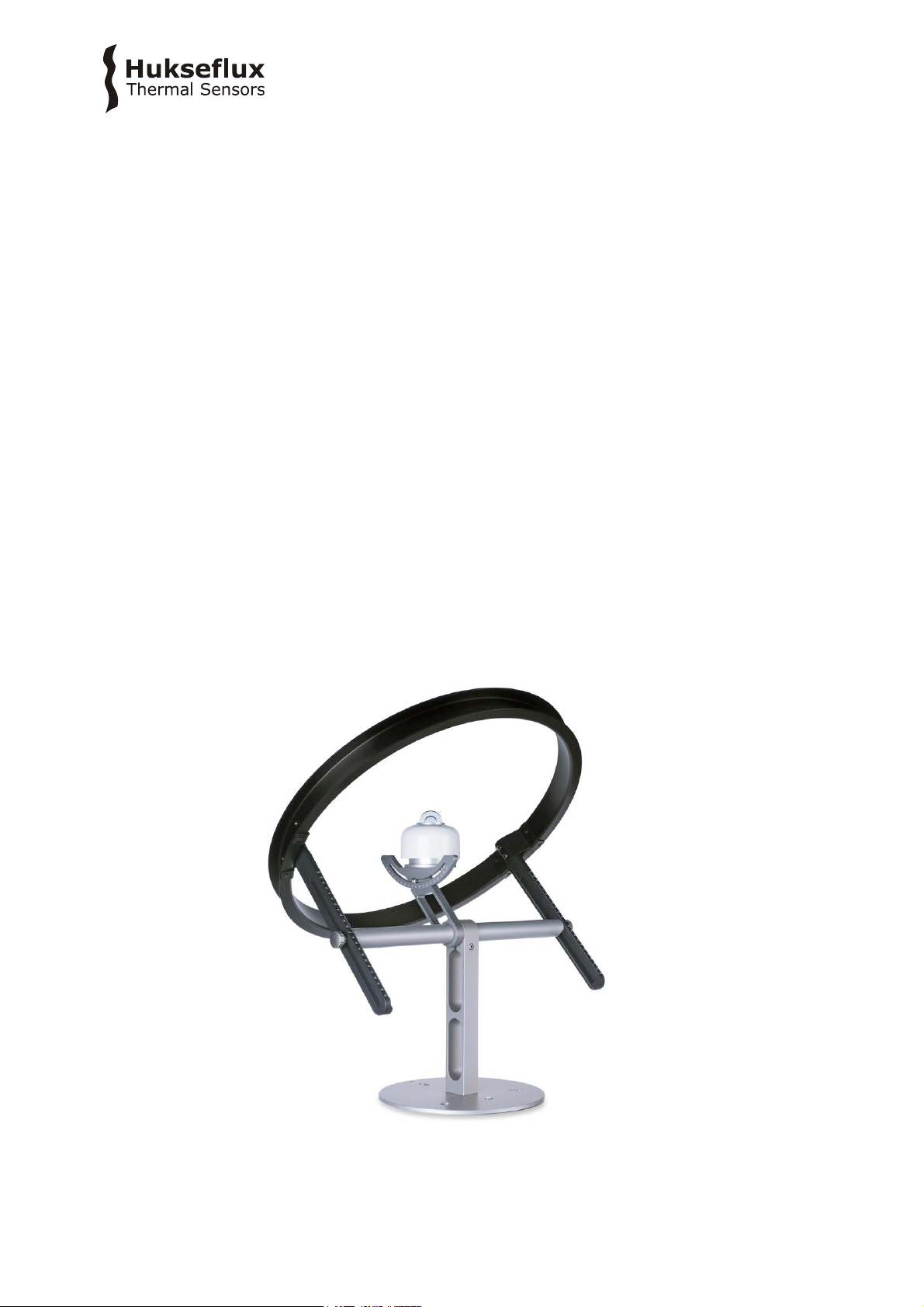
Figure 0.1 SHR02 shadow ring with a Hukseflux SR30 pyranometer, together forming a
diffusometer (a pyranometer is not included in SHR02 delivery).
SHR0 2 manu al v1 8 01 5/ 47
Page 6
Using SHR02 has several advantages:
relatively small size / light weight
low-investment alternative for a sun tracker with shading-disc
high accuracy when used with Hukseflux (low zero-offset) pyranometers
save costs on expensive external ventilation; compatible with SR30 with internal
ventilation
Suggested use of SHR02:
meteorological observations
building energy performance
solar energy studies
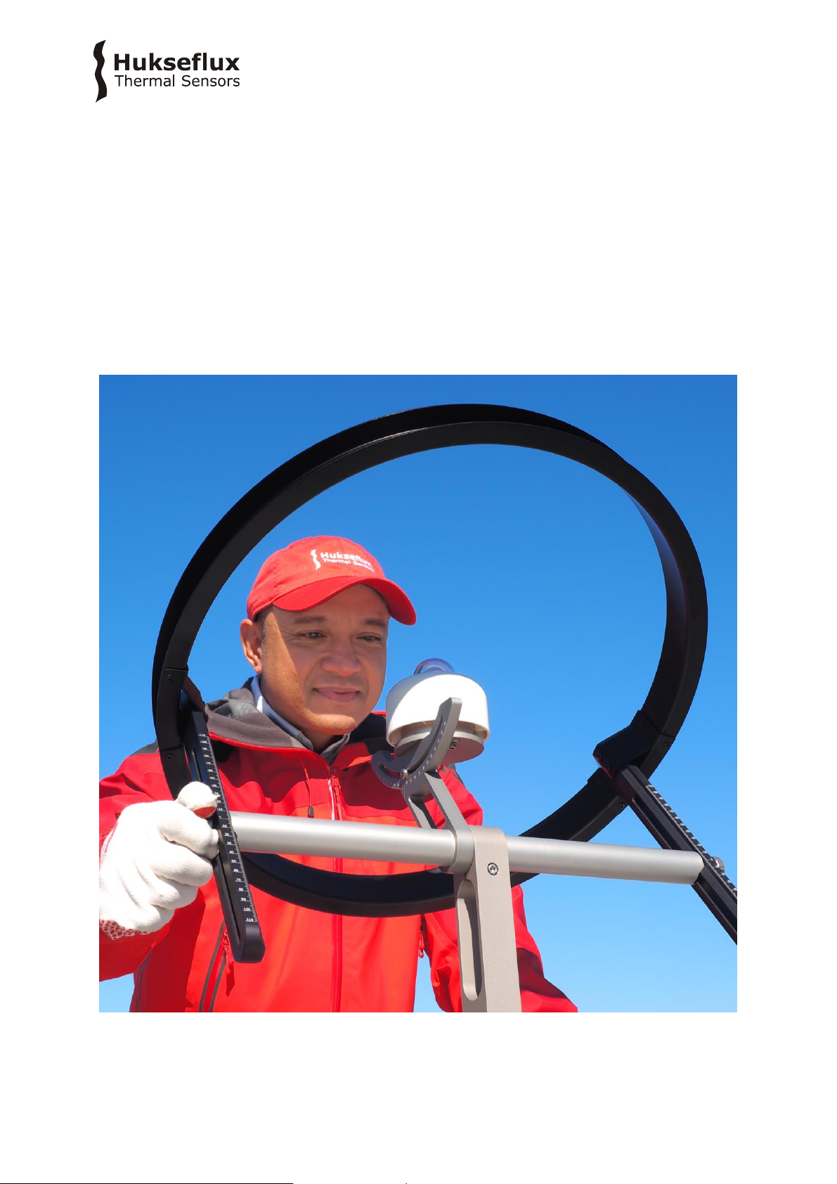
Figure 0.2 Installation of the SHR02 shadow ring with a Hukseflux pyranometer is easy.
SHR0 2 manu al v1 8 01 6/ 47
Page 7
The altitude of the sun varies throughout the year and this influences the shadow cast by
the shadow ring. Aside from adjusting the shadow ring on a regular basis to compensate
for this, it should be taken into account that part of the diffuse radiation obscured by the
shadow ring will change. Hukseflux provides a specifically tuned model that will aid the
user in setting up the SHR02 without the need for in-depth knowledge of diffusometers.
In this user manual a set-up table with required correction factors for the measured
diffuse radiation is provided, for a range of latitudes and declinations. The manual also
provides theory for creating individual models when even higher accuracy is required.
Compatible sensors are model SR30 and SR15 pyranometers. With the optional mounting
adapter, also models SR20, SR22 and SR25 may be used. This user manual covers
installation and use of SHR02 with pyranometer models SR30, SR15, SR20, SR22 and
SR25.
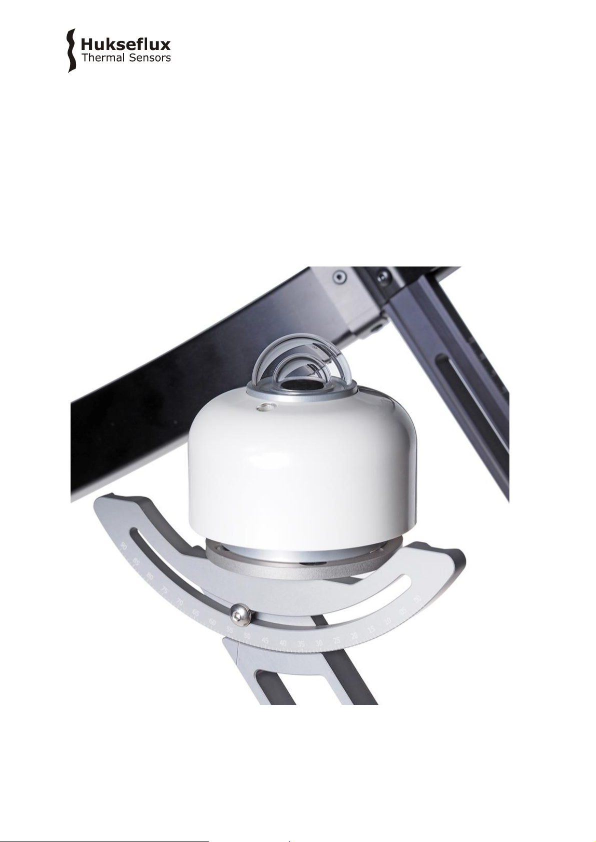
Figure 0.3 Pyranometer example: SR15, combined with SHR02 forming a diffusometer.
SHR0 2 manu al v1 8 01 7/ 47
Page 8
SHR02
Shadow ring for pyranometers, combined with a
pyranometer forming a diffusometer
(pyranometer is not included in SHR02 delivery)
PMA01
SR20 / SR22 / SR25 mounting adapter for
SHR02
1 Ordering and checking at delivery
1.1 Ordering and checking at delivery
The standard configuration of SHR02 is for use with SR15 / SR30 sensor.
Common options are:
Mounting adapter for SR20 / SR22 / SR25. Specify PMA01
Table 1.1.1 Ordering codes for SHR02
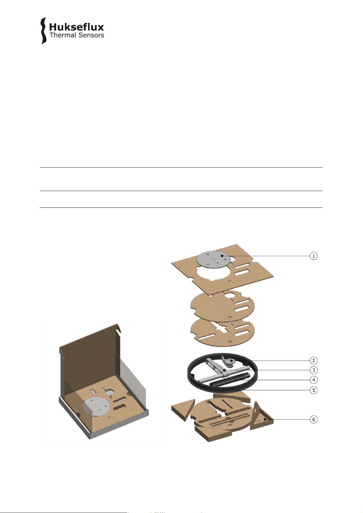
1.2 What’s in the box
SHR0 2 manu al v1 8 01 8/ 47
Page 9
Arriving at the customer, the delivery should include:
1. 1 x base plate
2. 1 x tilt adjustment stage (with engraved rotation scale in °)
with pyranometer mounting plate
3. 1 x central support, horizontal bar connected to pyranometer support arm
4. 2 x sliding bar, with engraved scale in mm
5. 1 x shadow ring
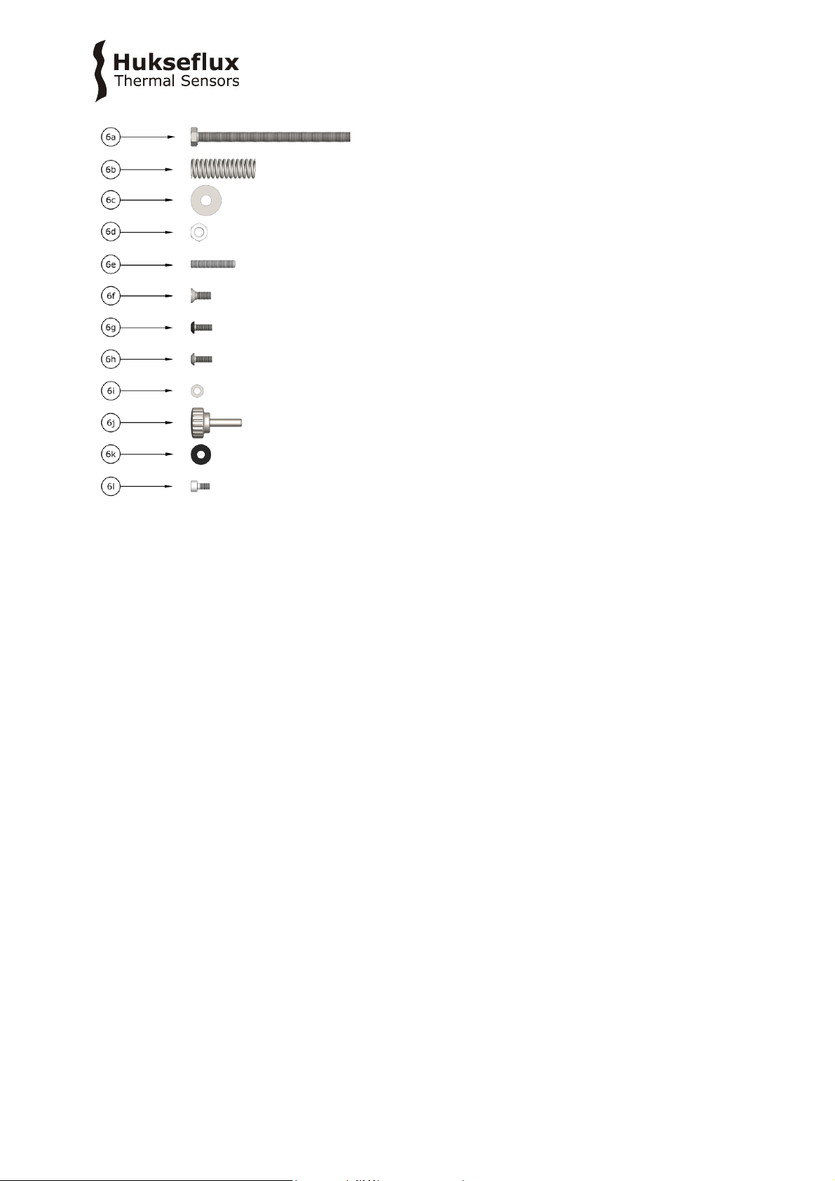
6. 1 x bag with nuts, bolts, set screws:
a. 3 x A4 stainless steel M8 x 120 hexagon head bolt
b. 3 x A4 stainless steel spring
c. 9 x A4 stainless steel M8 washer
d. 3 x A4 stainless steel M8 nut
e. 3 x A4 stainless steel M6 x 35 flat point socket set screw
f. 2 x A4 stainless steel M6 x 16 countersunk socket head cap bolt
g. 4 x A4 stainless steel M5 x 14 black button head cap bolt
h. 1 x A4 stainless steel M5 x 14 button head cap bolt
i. 1 x A4 stainless steel M5 washer
j. 2 x A4 stainless steel M6 x 35 thumbscrew
k. 2 x Plastic M6 washer
l. 2 x A4 stainless steel M5 x 10 socket cap head bolt
SHR0 2 manu al v1 8 01 9/ 47
Page 10

1.3 Recommended tooling
For assembling and mounting the shadow ring, the following tooling is recommended:
hex key 3 mm
hex key 4 mm
2 x spanner 13 mm
For levelling and or adjusting the shadow ring, the following tooling is recommended:
hex key 3 mm
hex key 4 mm
Consult your pyranometer user manual for tooling recommended for removal of the
pyranometer feet.
SHR0 2 manu al v1 8 01 10/47
Page 11
5
1
2
4
3
6
7
8
9
10
11
2 Instrument principle and theory
2.1 Instrument overview
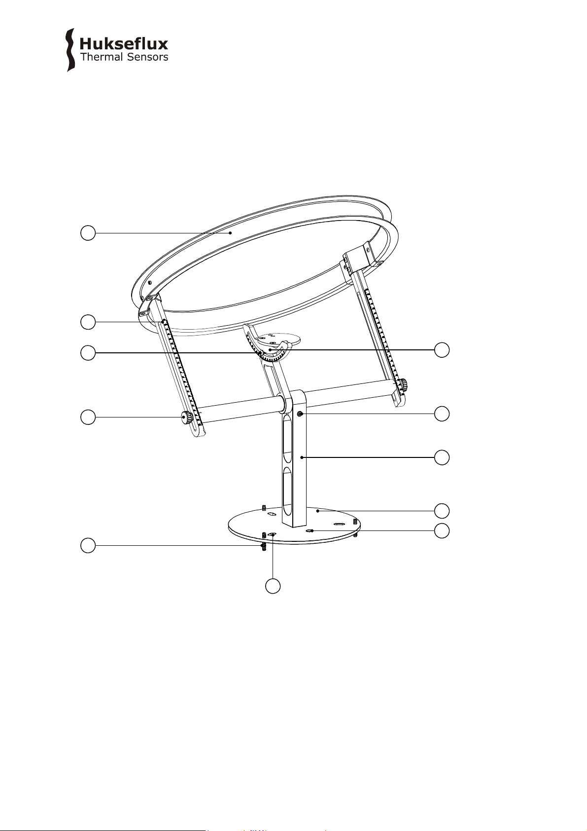
Figure 2.1.1 below shows SHR02 shadow ring, listing the main functional parts.
Figure 2.1.1 Overview of SHR02:
(1) levelling set screw
(2) thumbscrew for adjustment of sliding bars
(3) screw for adjustment of tilt stage
(4) sliding bar
(5) shadow ring
(6) tilt adjustment stage
(7) screw for latitude adjustment
(8) central support with horizontal bar connected to pyranometer support arm
(9) base plate
(10) bubble level
(11) mounting hole
SHR0 2 manu al v1 8 01 11/47
Page 12
Understanding the basic set-up, working principles and operation of a shadow ring
instrument is essential to attain accurate, reliable measurement data. This chapter
describes the basic principles, the main sources of error in data and some practical
considerations regarding installation and operation.
A view angle is an important specification for a shadow ring instrument. The view angle
is determined purely by the geometrical properties of the ring, assuming the sensitive
area of the pyranometer is small compared to the apparent width of the ring. The rims
on the ring not only provide mechanical stability but also minimize the seasonal
dependence of the view angle on the seasonal variations. The chapter on specifications
lists the mean value of the view angle. Due to the ring design, this view angle varies less
than 2 % throughout the year, depending on the declination. Note that the correction
factors provided in Appendix 8.2 of this manual do not assume this angle to be constant,
but take the dependence on the declination into account.
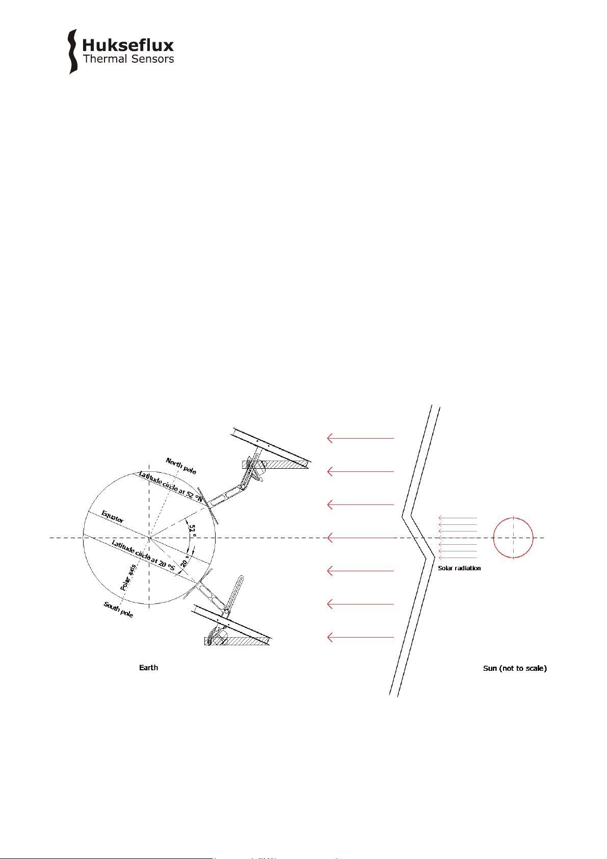
2.2 Operating principles
A shadow ring is used together with a pyranometer to measure diffuse global irradiance.
Direct radiation from the sun is blocked by the ring. To achieve this the entire day, the
ring is set up parallel to the equatorial plane; see Figure 2.2.1. This is practically done by
setting the plane of the ring compared to the horizon under an angle equal 90 ° minus
the local latitude in °.
Figure 2.2.1 The principle of a shadow ring
During the seasons, the sun’s trajectory changes its position in the sky due to variation
in the declination of the earth-sun system. The shadow ring is adjusted regularly to block
the pyranometer from the sun at all times. Adjustable sliding bars are used to put the
SHR0 2 manu al v1 8 01 12/47
Page 13
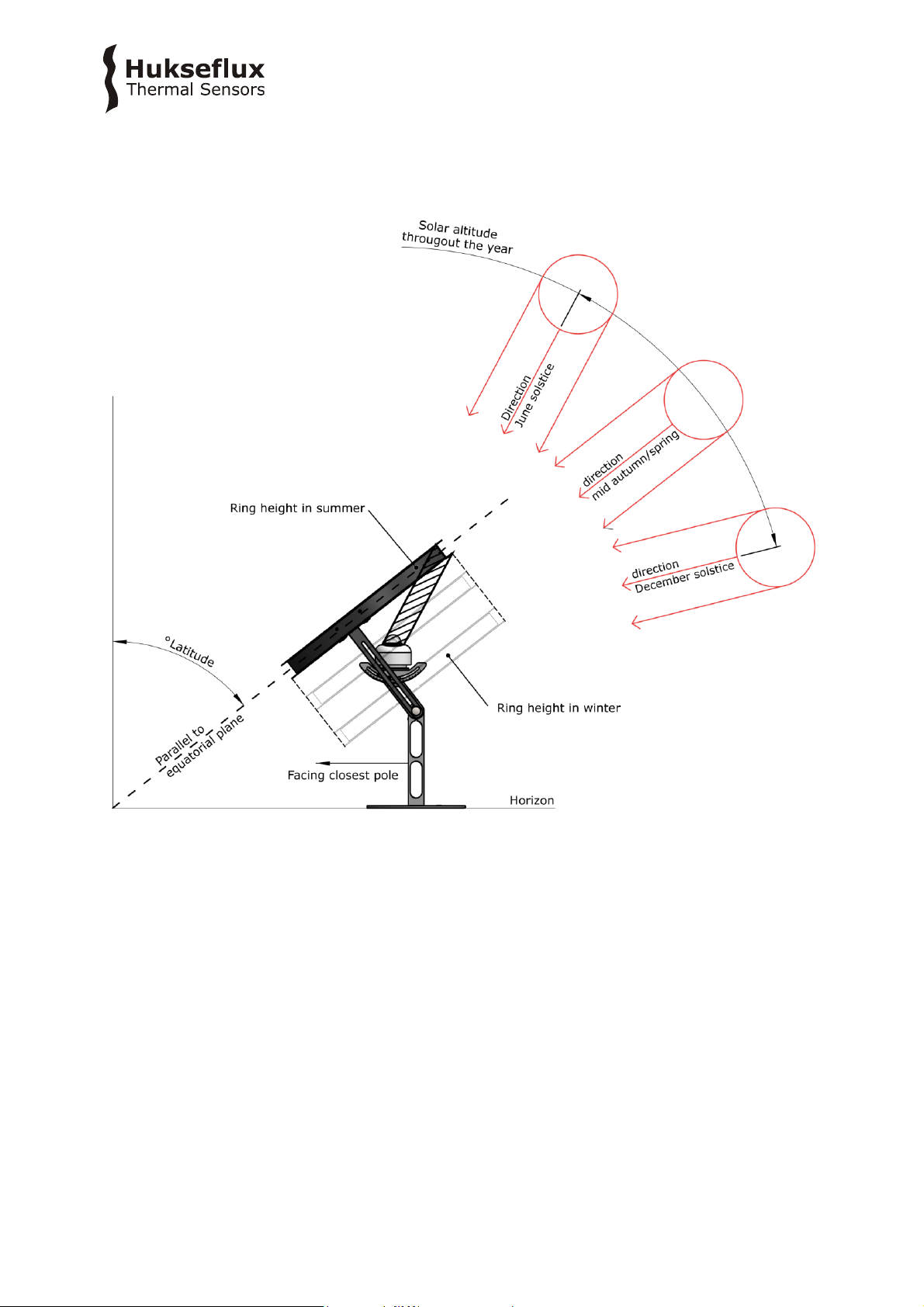
shadow ring in the correct position, compensating for the declination. Figure 2.2.2
schematically explains how a shadow ring is correctly set up. Depending on the time of
the year and the local latitude, adjustments need to be made between every day and
less than only once every 3 weeks.
Figure 2.2.2: Regular adjustment needs to be done to compensate for the position of
the sun in the sky throughout the year.
Most shadow rings are used with the pyranometer mounted horizontally. Using the
incorporated tilt adjustment stage, the pyranometer can also be mounted in a tilted
position. In this case, the diffuse irradiance in the tilted plane is measured. To keep the
pyranometer shaded, the ring must stay aligned with the equatorial plane.
2.3 Sources of error
There are two main sources of error that may affect the accuracy of the diffuse irradiance
component:
measurement errors
errors due to unintentional blockage by the ring
SHR0 2 manu al v1 8 01 13/47
Page 14

Measurement errors, inherent to the type of pyranometer and data logger used, can
generally be practically eliminated, but unintentional blockage by the ring is inherent to
the instrument operation principle and cannot be avoided. In the next two sections, these
sources of error are explained and, if possible, suggestions to remediate them are made.
2.3.1 Unintentional blockage of diffuse radiation
Seen from the centre of the pyranometer, the ring blocks a band of the sky aligned with
the trajectory of the sun during the day. Thus, not only the direct radiation from the sun
is blocked, but also part of the quantity of interest, the diffuse component. Apart from
other possible errors made, this always causes an underestimation of the diffuse
irradiance component. In other words, the measured diffuse component is a lower bound
for the actual diffuse irradiance component. Depending on the latitude, the declination
and the distribution of diffuse radiation, this underestimation is in the range of 5 % to 20
% or even larger.
In an attempt to improve on this and more closely approach the true value of the diffuse
irradiance, a correction factor can be calculated or estimated. This correction factor, f, is
defined by:
DHI = DHI
with DHI the diffuse radiation and DHI
the shadow ring. In terms of the corrected and uncorrected diffuse radiation the factor f
is given by:
f = 1 - DHI
The simplest possible model to calculate this correction factor assumes a uniform
distribution of the diffuse component and computes the fraction of sky that is blocked by
the ring, and is also known as the Drummond model. This correction factor depends on
the latitude and the declination and is given by:
f =2 (w+h |tan(dec)|) / (pi R) cos3(dec) [t0 sin(lat) sin(dec) + cos(lat) cos(dec) sin(t0)]
(Formula 2.3.1.3)
with R the diameter of the ring, h the height of the rims on the ring, w the width of the
ring, dec the declination, lat the latitude and t0 the hour angle at sunset and sunrise.
Refer to the specification table in Chapter 4 for the instrument dimensions. For
convenience, the table in Appendix 8.2 lists correction factors for a range of latitudes and
declinations. There are more sophisticated correction models possible, but these depend
on the local conditions and require more assumptions and tuning to local conditions.
These models are not discussed here.
/ (1 - f) (Formula 2.3.1.1)
obscured
the part of the diffuse radiation obscured by
obscured
/ DHI (Formula 2.3.1.2)
obscured
2.3.2 Measurement accuracy
A significant error source for diffuse sky radiation measurement is the zero offset a of the
pyranometer, i.e the signal at zero irradiation. Under clear sky conditions, the zero
SHR0 2 manu al v1 8 01 14/47
Page 15

irradiance signal may approach 30 W/m2 for a second class pyranometer and may be up
to 7 W/m2 for a secondary standard instrument. Since the diffuse irradiance component
is typically small, this may be up to 22 % for a second class pyranometer and 5 % for a
much more accurate secondary standard instrument under the same conditions. Thus
using pyranometers with a low zero offset, such as SR30 or SR25, will result in an
improved measurement accuracy. These instrument typically have a zero offset < 2
W/m2, resulting in an error in the diffuse component < 1 %. This is the most important
source of instrumentation error, but also the data logger accuracy needs to be
considered.
Since, as mentioned earlier, the diffuse sky radiation from a cloudless sky is small and
may be less than one tenth of the global radiation, relative contribution of pyranometer
measurement errors are large. Therefore, particularly in case of an analogue pyranometer,
the data acquisition should have a high resolution and small zero offset as well.
2.4 Daily adjustment
The position of the sun in the sky changes depending on the time of the year. To keep
the pyranometer shaded by the shadow ring, the position of the ring with respect to the
pyranometer is adjusted using the sliding bars. There are different approaches possible
to make the correct setting. The simplest, most pragmatic method is to centre the cast
shadow around the pyranometer outer dome every day at the time the sun is at its
highest point in the sky, at solar noon. This method does require daily attendance and is
therefore labour intensive, but may tolerate larger errors in the set-up and alignment of
the shadow ring.
An alternative method is to compile a table listing dates and corresponding settings.
There are several levels of sophistication possible within this approach. The table in
Appendix 8.2 lists a table that can be used at all latitudes and should be seen as a
starting point for a pyranometer that is installed horizontally. This table is computed
taking the shading effect of the flanges on the ring into account, and attempts to shade
the outer dome of the pyranometer for the majority of the time. The formula used to
compute this table is:
x
symmetrical
This equation results in a symmetrical shading around the centre of the pyranometer. In
the table, a setting for every 1 ° in declination is computed. In general, there are two
dates during the year at which the declination is the same. To improve on this, the
asymmetrical projection of the half-sphere formed by the pyranometer dome can be
taken into account as well. Since this projection depends on the angle of the sun with the
horizontal this equation depends on the latitude and the declination. Given a setting
x
symmetrical
x
dome
with r the diameter of the dome or half-sphere to be shaded. This correction becomes
particularly significant at large latitudes and small declinations.
= (R + h/2) tan(dec) (Formula 2.4.1)
the amount x
can be added to improve the ring adjustment:
dome
= r / 2 (1 – cos(lat - dec)) / cos(dec) (Formula 2.4.2)
SHR0 2 manu al v1 8 01 15/47
Page 16

2.5 General usage recommendations
Shadow ring devices must be used according the recommendations of ISO TR9901
paragraph 5.3 “pyranometer for diffuse solar radiation”, and WMO Guide 7.3.3.3
“installation of pyranometers for measuring diffuse sky radiation”. Note that the WMO
denotes a shadow ring device as “shading ring”.
Points of attention summarised:
pay attention to zero offset a of pyranometers;
carefully set the shadow ring alignment and check the alignment regularly;
use the appropriate correction factor to correct for the part of the DNI that is
obscured by the shadow ring;
make sure the shadow ring does not cast a shadow on neighbouring pyranometers;
use data acquisition with high accuracy and low zero offsets
SHR0 2 manu al v1 8 01 16/47
Page 17

STANDARDS FOR INSTRUMENT USE FOR HEMISPHERICAL SOLAR RADIATION
ISO STANDARD
EQUIVALENT
ASTM STANDARD
WMO
ISO/TR 9901:1990
Solar energy -- Field
pyranometers -- Recommended
practice for use
paragraph 5.3
“pyranometer for diffuse solar
radiation”
ASTM G183 - 05
Standard Practice for Field
Use of Pyranometers,
Pyrheliometers and UV
Radiometers
WMO-No. 8; Guide to
Meteorological Instruments
and Methods of Observation,
chapter 7, measurement of
radiation, 7.3 measurement
of global and diffuse solar
radiation
Paragraph 7.3.3.3
“installation of pyranometers
for measuring diffuse sky
radiation”
3 Standards and recommended practices
for use
Shadow rings and their associated pyranometers must be used in accordance with the
recommended practices of ISO, IEC, WMO and / or ASTM.
Pyranometers are classified according to the ISO 9060 standard and the WMO-No. 8
Guide.
3.1 General use for diffuse solar radiation measurement
Table 3.1.1 Standards with recommendations for instrument use in solar radiation
measurement
3.2 Specific use in meteorology and climatology
The World Meteorological Organization (WMO) is a specialised agency of the United
Nations. It is the UN system's authoritative voice on the state and behaviour of the
earth's atmosphere and climate. WMO publishes WMO-No. 8; Guide to Meteorological
Instruments and Methods of Observation, in which a table is included on “level of
performance” of pyranometers. Nowadays WMO conforms itself to the ISO classification
system.
SHR0 2 manu al v1 8 01 17/47
Page 18

STANDARDS FOR INSTRUMENT CLASSIFICATION
ISO STANDARD
EQUIVALENT
ASTM STANDARD
WMO
ISO 9060:2018
Solar energy -- specification and
classification of instruments for
measuring hemispherical solar and
direct solar radiation
Not available
WMO-No. 8; Guide to
Meteorological Instruments
and Methods of Observation,
chapter 7, measurement of
radiation, 7.3 measurement
of global and diffuse solar
radiation
3.3 Pyranometer classification standard
Table 3.3.1 Standards for pyranometer classification. See the appendix for definitions of
pyranometer specifications, and a table listing the specification limits.
SHR0 2 manu al v1 8 01 18/47
Page 19

SHR02 SPECIFICATIONS
Function
forming a diffusometer when combined with a
pyranometer
Diffusometer measurand
diffuse solar radiation in W/m2
Diffusometer measurand in SI
radiometry units
irradiance in W/m2
Expected DNI range
0 to 250 W/m2
Instrument compatibility
SR30, SR15 pyranometers (recommended)
Instrument compatibility
SR25, SR22, SR20 pyranometers
(with optional mounting adapter)
Diffusometer zero offset a
with SR30: 2 W/m2
with SR15: 5 W/m2
with SR25: 1 W/m2
with SR20: 5 W/m2
Use with heating
with SR30 and SR25
Use with ventilation
with SR30
MATERIALS
Main construction elements
anodised aluminium
Main construction elements, black parts)
anodised aluminium, anaorganic dye
Fasteners
stainless steel A4
DIMENSIONS
Ring inner diameter
476 x 10-3 m
Ring rim height
20
Ring width
44
Ring profile
U-profile
Average view angle
10.6 °
Ring height/radius ratio
0.185
Maximum diameter shaded area
40 x 10-3 m
Pyranometer tilt angle range
-90 to 90 °
Sliding bar resolution
1 x 10⁻³ m
Sliding bar accuracy
±0.5 x 10⁻³ m
Sliding bar range
±110 x 10-3 m
Maximum bounding box height
770 x 10-3 m
Maximum bounding box depth
725 x 10-3 m
Maximum bounding box width
516 x 10-3 m
Horizontal bar height
246 x 10-3 m
Base plate diameter
250 x 10-3 m
Net weight
3.75 kg
Gross weight (including packaging)
5.90 kg
Packaging
box of 560 x 610 x 80 mm
OTHER SPECIFICATIONS
Rated operating temperature range
-40 to +80 °C
Levelling
adjustable levelling screws and bubble level are
included, bubble level of SHR02 and of mounted
pyranometer are used
11.
4 Specifications
4.1 Specifications of SHR02
SHR02 allows making diffuse solar irradiance measurements with pyranometers. In this
combination it forms a “diffusometer”. SHR02 should be used in accordance with the
recommended practices of ISO, IEC, WMO and ASTM.
Table 4.1.1 Specifications of SHR02
SHR0 2 manu al v1 8 01 19/47
Page 20

Table 4.1.1 Specifications of SHR02 (continued)
Bubble level accuracy
< 0.1 ° bubble entirely in ring
Mounting screws
included
Application of correction factors
responsibility of the user
(see appendix)
Standards governing use of the
instrument
ISO/TR 9901:1990 Solar energy -- Field pyranometers
-- Recommended practice for use
ASTM G183 - 05 Standard Practice for Field Use of
Pyranometers, Pyrheliometers and UV Radiometers
WMO-No. 8; Guide to Meteorological Instruments and
Methods of Observation, chapter 7, measurement of
radiation, 7.3 measurement of global and diffuse solar
radiation
INSTALLATION AND USE
Required adjustment interval
according to adjustment table
Manual adjustment
use the adjustment table in Appendix 8.2
this table refers to the scales which are engraved in
the sliding bars
Mounting
follow directions of this manual
Required azimuth (north-south)
alignment
1 °
Required zenith alignment (levelling)
1 °
Required latitude alignment of sliding
bars
1 °
OPTIONS
mounting adapter for pyranometer model
SR20, SR22, SR25
option code = PMA01
SHR0 2 manu al v1 8 01 20/47
Page 21

Ø 250
Ø 516
246
Max width: 725
Max height: 770
4.2 Dimensions of SHR02
Figure 4.2.1 Dimensions of SHR02 in x 10-3 m. The depicted pyranometer is not
included in SHR02 delivery.
SHR0 2 manu al v1 8 01 21/47
Page 22

5 Installation of SHR02
5.1 Assembly
The shadow ring assembly takes about thirty minutes. Before assembling, ensure that
the set is complete; see the chapter on ordering and checking at delivery.
The intended result can be seen on the cover of this manual. An exploded view followed
by the recommended assembly steps is shown in Figure 5.1.1. The numbers depicted in
the exploded view match the part numbers as described in the What’s in the box chapter.
The part numbers are referenced throughout the assembly guide, in the format [#],
where # is the part number.
Figure 5.1.1 Exploded view of the SHR02 for assembly overview
SHR0 2 manu al v1 8 01 22/47
Page 23

5.1.1 Step 1
Take the base plate [1] and the pre-assembled central support with horizontal bar [3].
Fasten the two with 2 x countersunk M6 x 16 mm screws [6f], ensuring that the bubble
level on the base plate is facing towards the central support. Fasten the screws with the
long end of a 4 mm hex key in the screw to prevent over-tightening and damaging of
threads, see Figure 5.2.1.1
Figure 5.2.1.1 Assembling the base plate to the central support
SHR0 2 manu al v1 8 01 23/47
Page 24

5.1.2 Step 2
Place the assembly of Step 1 on a flat surface. Using a 4 mm hex key, loosen the screw
of the clamp in the central support [3] to release the horizontal bar. Turn the horizontal
bar so that the in the pyranometer support is in the upright position, and fasten the
screw again with the long end of the 4 mm hex key to keep it in place.
Figure 5.1.2.1 Adjusting the pyranometer support arm
SHR0 2 manu al v1 8 01 24/47
Page 25

5.1.3 Step 3
Attach the tilt adjustment stage with the sensor mounting plate [2] to the pyranometer
support that has been pointed upwards in the previous step. Insert the uncoated M5 x 14
mm button socket head cap bolt [6h] with the M5 washer [6i] through the tilt adjustment
stage and into the pyranometer support arm. Tighten the screw with the long end of 3
mm hex key.
Figure 5.1.3.1 Attaching the tilt adjustment stage to the pyranometer support arm
SHR0 2 manu al v1 8 01 25/47
Page 26

5.1.4 Step 4
Attach the two sliding bars [4] to the ends of the horizontal bar using the thumbscrews
[6j] and plastic M6 washers [6k]. The flat end of the sliding bars should point upwards.
Adjust the position of the sliding bars so that position ‘0’ aligns with the position marker
engraved on the horizontal bar. When in position, lock the sliding bars in place with the
thumbscrews.
Figure 5.1.4.1 Attaching a sliding bar to the horizontal bar
SHR0 2 manu al v1 8 01 26/47
Page 27

5.1.5 Step 5
The shadow ring [5] has two brackets attached to it. Fit the shadow ring onto the sliding
bars [4]. The flanges folding over the shadow ring should be facing downwards. Imagine
a line through both brackets; this divides the shadow ring into two areas. The bigger
area of the ring should be pointing towards the bubble level on the base plate [1].
Fasten de brackets of the shadow ring to the sliding bars with 4 M5 x 14 mm black
button socket head cap bolt [6g] by using the long end of a 3 mm hex key.
Figure 5.1.5.1 Attaching the ring to the sliding bars
SHR0 2 manu al v1 8 01 27/47
Page 28

The assembly is now complete and should look like in Figure 5.1.5.2.
Figure 5.1.5.2 The shadow ring when set up correctly
5.2 Site selection
Follow the general directions in the pyranometer manual. The main requirement is to
have a horizon that is as free from obstacles as possible.
SHR0 2 manu al v1 8 01 28/47
Page 29

5.3 On site mounting
The installation of a pyranometer on a shadow ring is similar to that of a pyranometer
which measures GHI. The distance to a neighbouring pyranometer should be
sufficient to guarantee that the shading ring does not cast a shadow on it. This may be
more difficult at high latitudes where the solar zenith angle can be very low.
Mounting of the shadow ring can be done with the three mounting holes on the base
plate. M8 bolts [6a] with springs [6b], washers [6c] and nuts [6d] are included, which
are needed for easy levelling.
5.3.1 Hole pattern and relation to azimuth alignment
Before drilling holes or otherwise preparing the mounting platform, make sure the
horizontal bar of the instrument can be aligned perpendicular to the true (as opposed to
the magnetic) north-south axis. Figure 5.3.1.1 depicts the required orientation. See the
next subchapter on alignment for detailed alignment instructions.
Figure 5.3.1.1 Required orientation of shadow ring
SHR0 2 manu al v1 8 01 29/47
Page 30

When the correct azimuthal (north-south) orientation is determined, the mounting holes
can be drilled. Please refer to the mounting pattern in Appendix 8.1 as a template to
scale for proper mounting/drilling, so that SHR02 is installed in the required orientation.
5.3.2 Preferred spring-loaded mounting
The instrument is supplied with mounting bolts [6a], including springs [6b], washers [6c]
and nuts [6d]. Recommended mounting is shown in Figure 5.3.2.2. Before mounting the
instrument to the mounting platform, insert the three M6 x 35 flat point socket set
screws [6e] into the base plate [1]. The screws should be inserted roughly half way into
the base plate. Place a washer between the bolt and the base plate [1]. The spring
should be attached with washers on both ends. This will keep the spring in place and
reduce wear in you mounting platform.
Figure 5.3.2.2 SHR02 mounting fasteners. For easy levelling of the instrument, insert
the bolts pointing downwards. Use the washers as shown to keep the springs in place.
SHR0 2 manu al v1 8 01 30/47
Page 31

5.4 Alignment
The shadow ring needs to be aligned so that only diffuse radiation is observed by the
pyranometer. Aligning the instrument is done in four steps:
1. azimuthal alignment (north-south orientation)
2. zenithal alignment (levelling)
3. latitudinal alignment (tilt of the shadow ring)
4. solar altitude adjustment (shadow ring height versus the pyranometer)
5.4.1 Step 1: Azimuthal alignment
The highest part of the shadow ring should cast a shadow on the pyranometer when the
sun is at its highest altitude of the day. This is obtained by adjusting the azimuth so that
the back side (lowest part of the shadow ring) is facing to the nearest pole; the northsouth orientation.
The north-south orientation can be obtained using three methods:
using a map
using GPS coordinates
using the sun transit time (“solar noon”)
The recommended method is by using a map. This method provides the highest accuracy.
5.4.1.1 Azimuthal alignment using a map
Find your current location on map and mark it on the map. Draw a line directly north or
south of that location and try to find an easily distinguishable landmark along that line,
but one that is still as far away as possible. Find the landmark in your surroundings and
draw an imaginary line from your marked starting point towards the landmark. The
shadow ring should be oriented along the found north/south line as depicted earlier in
Figure 5.8.1.1. Ensure that the side of the central support, the side with the holes in it, is
set parallel to the north/south line. Setting a landmark in the far distance will increase
the accuracy of the alignment.
5.4.1.2 Azimuthal alignment using GPS coordinates
This technique can be used when it is hard to find a landmark directly north or south of
the location at which the shadow ring should be installed.
Record the GPS coordinates of the location at which the shadow ring will be installed.
Find a coordinate north or south from the recorded location that is as far away as
possible, but still visible from the starting location. Travel to the set location and place
marker that will be visible from the starting location. Travel back to the starting location
and draw a line between the starting coordinate and the placed marker. This line should
now align with true north/south. The shadow ring should be oriented along the found
SHR0 2 manu al v1 8 01 31/47
Page 32

north/south line as depicted earlier in Figure 5.3.1.1. Ensure that the side of the central
support, the side with the holes in it, is set parallel to the north/south line.
5.4.1.3 Azimuthal alignment using the sun transit time
The sun transit time, also known as solar noon, is the time of day when the sun is
reaches it highest position in the sky. At this time, the shadow of the instrument can be
used to align itself. At solar transit time, turn the instrument so that the shadow of the
vertical central support is parallel to sides of the central support, the sides with the
vertical slot. See Figure 5.4.1.3.1 for a render of how the the shadow should align. This
method provides a less accurate alignment than the previous methods, since the sun is
only at its highest point for roughly two minutes and the referencing line is much shorter
than when set out with a map. Besides this, the position of the sun’s highest point
changes with respect to the earths rotation axis throughout the year according to the
“equation of time”.
Figure 5.4.1.3.1 Aligning the shadow parallel to the vertical support
Note: solar transit time varies with each day and also depends on the location on earth.
The most accurate alignment achievable using this method can be attained when
performing the alignment during an equinox.
SHR0 2 manu al v1 8 01 32/47
Page 33

5.4.2 Step 2: Zenithal alignment
After the instrument is assembled, oriented to true north/south and mounted on a
platform, it needs to be levelled. To do so, the base plate has three hexagon socket set
screws [6e] which can be adjusted with a 3 mm hex key. Adjust the screws until the
bubble level next to the vertical support has its bubble in the centre of its inner ring. If
the instrument was mounted using the recommended springs, levelling can be done
solely by adjusting the levelling screws. If the instrument was mounted without using the
recommended springs, loosen the mounting bolts a little to allow movement for levelling.
Fasten again after levelling.
Figure 5.4.2.1 Levelling the instrument. Set screws [6e], bubble level (10)
5.4.3 Step 3: Latitudinal alignment
The shadow ring needs to be tilted so that it is parallel to the equatorial plane. The
required tilt depends on the latitudinal positon on earth. The shadow ring can be set
parallel to the equatorial plane by setting the tilt adjustment stage to the corresponding
latitude: round the determined latitude to a whole number and set the tilt adjustment
stage to that number; see Figure 5.4.3.1.
For example: Delft, the Netherlands is located at 52.0116° N, 4.3571° E . The latitude
(North) is 52 °, so the rotating tilt adjustment stage should be secured at 52 °.
SHR0 2 manu al v1 8 01 33/47
Page 34

Figure 5.4.3.1 Setting the tilt adjustment stage to the corresponding latitude
After setting up a correct latitudinal alignment, the pyranometer should be mounted. The
mounting procedure depends on the type of pyranometer. For all types of mounted
pyranometers: ensure that the cable of the pyranometer is facing towards the closest
pole.
SHR0 2 manu al v1 8 01 34/47
Page 35

5.4.3.1 Mounting an SR15 or SR30 pyranometer
Remove the feet from the pyranometer before mounting. Mount the pyranometer on the
pyranometer mounting plate, which is connected to the tilt adjustment stage [2], and
secure the pyranometer with two M5x10 bolts [6i], see Figure 5.4.3.1.1. The bolts should
fit into the inner holes in the mounting plate.
Figure 5.4.3.1.1 Mounting an SR15 pyranometer on SHR02
SHR0 2 manu al v1 8 01 35/47
Page 36

5.4.3.2 Mounting an SR20, SR22 or SR25 pyranometer
When mounting an SR20, SR22 or SR25 pyranometer, a mounting adapter is required,
which can be ordered separately (see chapter on ordering and checking at delivery).
Remove the feet from the pyranometer before mounting. Mount the pyranometer on the
pyranometer mounting plate, which is connected to the tilt adjustment stage [2], and
secure the pyranometer with two M5x20 bolts; see Figure 5.4.3.2.1. These bolts are
provided with the mounting adapter. The bolts should fit into the outer holes in the
mounting plate.
Figure 5.4.3.2.1 Mounting an SR20 pyranometer on SHR02, using the optional
mounting adapter PMA01
After mounting the sensor, release the bolt on the central support, freeing the horizontal
bar for rotational adjustments. Turn the horizontal bar until the bubble level of the
pyranometer is level in that axis of rotation. Then, tighten the screw again. See Figure
5.4.3.2.2 for reference.
SHR0 2 manu al v1 8 01 36/47
Page 37

Figure 5.4.3.2.2 Rotational axis of the horizontal bar for levelling the instrument after
placement of the pyranometer
As a reference for levelling of the entire instrument, use the bubble level on the base
plate. Only use the bubble level of the pyranometer for setting the correct latitudinal
alignment.
Note: The pyranometer bubble level of secondary standard pyranometers is accurate to
0.1 degrees. This accuracy is not needed when measuring diffuse radiation.
5.4.4 Step 5: day of year adjustment
The maximum altitude of the sun varies throughout the year. The changing angle will
cause the shadow created by the shadow ring to vary along with this change. To
compensate for this change, the sliding bars can be used to adjust the position of the
shadow ring in respect to the pyranometer.
Look up the required setting of the sliding bars corresponding with the day of the year in
table in Appendix 8.2. Loosen the thumbscrews and slide the sliding bars to the correct
SHR0 2 manu al v1 8 01 37/47
Page 38

position. Retighten the thumbscrews to lock the found position. The sliding bars and
thumbscrews are designed to prevent the shadow ring from sliding down abruptly when
the knobs are loosened simultaneously. This feature prevents damage to the instrument.
If the bars seem to be stuck, gently slide one bar back a little, then try again.
Figure 5.4.4.1 Sliding the bars to the correct position using the thumbscrews
SHR0 2 manu al v1 8 01 38/47
Page 39

MINIMUM RECOMMENDED PYRANOMETER + SHADOW RING MAINTENANCE
INTERVAL
SUBJECT
ACTION
1
according to
adjustment
table
manual
adjustment
adjust sliding bars
2
1 week
data analysis
compare measured data to maximum possible / maximum
expected diffuse DNI irradiance and to other measurements
nearby (redundant instruments).
Use correction factors for DHI.
Compare to GHI measurements.
Also historical seasonal records can be used as a source for
expected values. Analyse night time signals. These signals
may be negative (down to - 5 W/m2 on clear windless nights),
for most pyranometers, less for Hukseflux SR25 and SR30 due
to zero offset a.
3
2 weeks
cleaning
use a soft cloth to clean the dome of the pyranometers,
persistent stains can be treated with soapy water or alcohol
4
6 months
inspection
Inspect shadow ring mounting + alignment
inspect cable quality, inspect connectors, inspect mounting
position, inspect cable, clean instrument, clean cable, inspect
levelling, change instrument tilt in case this is out of
specification, inspect mounting connection, inspect interior of
dome for condensation
5
2 years
pyranometer
recalibration
recalibration by side-by-side comparison to a higher standard
instrument in the field according to ISO 9847
request “power user” status and a password at the factory
permitting to write to registers holding the sensitivity and the
calibration history data via the Sensor Manager (digital sensors)
6
> 5 years
desiccant
replacement
desiccant replacement. Typically during calibration desiccant is
replaced. Ask the manufacturer for directions
7 lifetime
assessment
judge if the instrument should be reliable for another 2 years,
or if it should be replaced
8 parts
replacement
if applicable / necessary replace the parts that are most
exposed to weathering; cable, connector. NOTE: use Hukseflux
approved parts only
6 Maintenance
6.1 Recommended maintenance and quality assurance
For maintenance and trouble shooting of the pyranometer mounted on SHR02, consult the
manual of this pyranometer. SHR02 and its pyranometers can measure reliably at a low
level of maintenance in most locations. Usually unreliable measurements will be detected
as unreasonably large or small measured values. As a general rule this means that regular
visual inspection combined with a critical review of the measured data, preferably checking
against other measurements, is the preferred way to obtain a reliable measurement.
Table 6.1.1 Recommended maintenance of diffusometers. If possible the data analysis
and cleaning (2 and 3) should be done on a daily basis.
SHR0 2 manu al v1 8 01 39/47
Page 40

7 Trouble shooting
For maintenance and trouble shooting of the pyranometer mounted on SHR02, consult
the manual of this pyranometer. SHR02 and its recommended pyranometers can
measure reliably at a low level of maintenance in most locations. Usually unreliable
measurements will be detected as unreasonably large or small measured values. As a
general rule this means that regular visual inspection combined with a critical review of
the measured data, preferably checking against other measurements, is the preferred
way to obtain a reliable measurement.
7.1 Irradiance level too high
Expected DNI levels are between -10 (zero offset) and 250 W/m2. In case the measured
irradiance is too high, the shadow ring might be above or below the perceived trajectory
of the sun. The following can be done to ensure the instrument is properly aligned:
go the site and see what occurs
consult your adjustment scheme and check if the sliding bars are set at the
correct setting for the day of the year
check if the rotating tilt adjustment stage is set to the correct latitude of its
position on earth
check if the instrument is aligned properly to true north/south (see Appendix 8.2)
it is not aligned 180 degrees turned
7.2 Alignment errors
Alignment errors can cause the shadow ring to not fully obstruct direct solar radiation
from reaching the pyranometer. This will result in measuring higher irradiance levels
than the actual diffuse solar radiation. Expected DNI levels are between -10 (zero offset)
and 250 W/m2. Regular inspection of the shadow ring ensures that the instrument is set
up correctly.
7.2.1 Incorrect azimuthal alignment
As is explained in Chapter 2.3.2 and 5.4.1, it is important that the shadow ring has
proper azimuthal alignment (aligned correctly to the north/south axis). If there are large
errors in orientation, the alignment error will be easily visible at the sun transit time. If
the shadow ring is properly aligned, the shadow cast by shadow ring should look as
shown in Figure 7.2.1.1.
SHR0 2 manu al v1 8 01 40/47
Page 41

Figure 7.2.1.1 Shadow cast by the shadow ring when correctly aligned
If the azimuthal alignment is off by a few degrees or more, the tangent at the symmetry
plane (through the centre of the dome) of the cast shadow will not be parallel to the
horizontal bar; see Figure 7.2.1.2. For small angles, < 5 °, it will be hard to judge if the
shadow is parallel, so this method will only be useful to detect large alignment errors.
Also, the tangent of the shadow can only be perfectly parallel during an equinox.
Figure 7.2.1.2 Tangent to cast shadow should be parallel to axle
SHR0 2 manu al v1 8 01 41/47
Page 42

7.2.2 Incorrect zenithal/latitudinal alignment
As is explained in Chapter 2.2 and 5.4.3/5.4.4, the ring of the shadow ring has to be set
parallel to the equatorial plane. In a normal, non-tilted set-up, the pyranometer should
be level. This can be adjusted by setting the tilt adjustment stage. Errors in this set-up
are hard to detect by observing the shadow ring. To ensure correct alignment, run
through chapter 5.4.3 and 5.4.4 again.
7.2.3 Incorrect day of year adjustment
As is explained in Chapter 2.2 and 5.4.4, the shadow ring will have to be adjusted
regularly using the sliding bars to compensate for the change in solar altitude. To check if
the sliding bars are set correctly, refer to figure 7.2.3.1 and 7.2.3.2; the shadow should
be cast to envelope the entire outer dome of the pyranometer. This can best be judged
during solar transit time, as the shadow will turn around the pyranometer during the day,
making it hard to distinguish azimuthal, zenithal/latitudinal errors from errors in the
sliding bar setting.
During solar transit time, a shadow as shown in Figure 7.2.3.1 shows that the sliding
bars are set too high, casting the shadow further away over the pyranometer. Figure
7.2.3.2 shows the shadow when the sliding bars are set too low.
Figure 7.2.3.1 Sliding bars set too high Figure 7.2.3.2 Sliding bars set too low
SHR0 2 manu al v1 8 01 42/47
Page 43

8 Appendices
SHR0 2 manu al v1 8 01 43/47
Page 44

Page 45

8.1 Mounting pattern
Please ensure the image is printed to scale (10 = 10 mm)
SHR02 manual
Page 46

Start date End date setting [mm] Declination (negative for southern hemisphere)
-90 -85 -80 -75 -70 -65 - 60 - 55 -50 - 45 -40 - 35 -30 - 25 - 20 -15 - 10 -5 0 5 10 15 20 25 30 35 40 45 50 55 60 65 70 75 80 85 90
22/Dec 30/Nov -107 1.16 1.16 1.15 1.15 1.15 1.14 1.14 1.14 1.14 1.14 1.14 1.14 1.14 1.14 1.13 1.13 1.12 1.12 1.11 1.1 1.1 1.09 1.08 1.07 1.06 1.05 1.04 1.03 1.02 1.01 1.01 1 1 1 1 1 1
13/Jan 12/Nov -90 1.15 1.15 1.15 1.14 1.14 1.14 1.14 1.14 1.14 1.14 1.14 1.14 1.14 1.14 1.14 1.13 1.13 1.12 1.12 1.11 1.1 1.09 1.08 1.07 1.06 1.05 1.04 1.03 1.03 1.02 1.01 1 1 1 1 1 1
31/Jan 31/Oct -71 1.13 1.13 1.12 1.12 1.12 1.12 1.13 1.13 1.14 1.14 1.14 1.14 1.14 1.14 1.14 1.14 1.13 1.13 1.12 1.12 1.11 1.1 1.09 1.08 1.07 1.06 1.05 1.04 1.03 1.03 1.02 1.01 1 1 1 1 1
12/Feb 21/Oct -56 1.1 1.1 1.1 1.1 1.1 1.11 1.12 1.12 1.13 1.13 1.14 1.14 1.14 1.14 1.14 1.14 1.14 1.14 1.13 1.13 1.12 1.11 1.1 1.09 1.08 1.07 1.06 1.05 1.04 1.03 1.02 1.01 1.01 1 1 1 1
22/Feb 12/Oct -41 1.08 1.08 1.08 1.08 1.09 1.1 1.1 1.11 1.12 1.13 1.13 1.14 1.14 1.14 1.14 1.14 1.14 1.14 1.13 1.13 1.12 1.12 1.11 1.1 1.09 1.08 1.07 1.06 1.05 1.04 1.03 1.02 1.01 1 1 1 1
03/Mar 04/Oct -28 1.05 1.05 1.06 1.06 1.07 1.08 1.09 1.1 1.11 1.12 1.12 1.13 1.13 1.14 1.14 1.14 1.14 1.14 1.14 1.13 1.13 1.12 1.12 1.11 1.1 1.09 1.08 1.07 1.06 1.05 1.04 1.03 1.02 1.01 1 1 1
11/Mar 26/Se p -14 1.03 1.03 1.04 1.05 1.06 1.07 1.08 1.09 1.1 1.11 1.11 1.12 1.13 1.13 1.13 1.14 1.14 1.14 1.14 1.13 1.13 1.13 1.12 1.11 1.11 1.1 1.09 1.08 1.07 1.06 1.05 1.04 1.03 1.02 1.01 1 1
19/Mar 19/Se p -1 1.01 1.02 1.03 1.04 1.05 1.06 1.07 1.08 1.09 1.1 1.1 1.11 1.12 1.12 1.13 1.13 1.13 1.14 1.14 1.13 1.13 1.13 1.12 1.12 1.11 1.1 1.1 1.09 1.08 1.07 1.06 1.05 1.04 1.03 1.02 1.01 1
26/Mar 13/Se p 10 1 1.01 1.02 1.03 1.04 1.05 1.06 1.07 1.08 1.09 1.1 1.11 1.11 1.12 1.12 1.13 1.13 1.13 1.13 1.13 1.13 1.13 1.13 1.12 1.12 1.11 1.1 1.09 1.09 1.08 1.07 1.06 1.05 1.04 1.02 1.01 1.01
01/Apr 06/Sep 21 1 1 1.01 1.02 1.03 1.04 1.05 1.06 1.07 1.08 1.09 1.1 1.11 1.12 1.12 1.13 1.13 1.13 1.14 1.14 1.14 1.13 1.13 1.13 1.12 1.12 1.11 1.1 1.09 1.08 1.08 1.07 1.06 1.04 1.03 1.02 1.02
08/Apr 31/Aug 32 1 1 1 1.01 1.02 1.04 1.05 1.06 1.07 1.08 1.09 1.1 1.1 1.11 1.12 1.13 1.13 1.13 1.14 1.14 1.14 1.14 1.14 1.13 1.13 1.12 1.12 1.11 1.1 1.09 1.09 1.08 1.07 1.06 1.05 1.04 1.04
14/Apr 25/Aug 42 1 1 1 1.01 1.02 1.03 1.04 1.05 1.06 1.07 1.08 1.09 1.1 1.11 1.12 1.12 1.13 1.13 1.14 1.14 1.14 1.14 1.14 1.14 1.13 1.13 1.12 1.12 1.11 1.1 1.09 1.09 1.08 1.07 1.06 1.06 1.06
20/Apr 20/Aug 50 1 1 1 1.01 1.01 1.02 1.03 1.04 1.05 1.07 1.08 1.09 1.09 1.1 1.11 1.12 1.13 1.13 1.14 1.14 1.14 1.14 1.14 1.14 1.14 1.13 1.13 1.12 1.12 1.11 1.1 1.09 1.09 1.08 1.07 1.07 1.07
25/Apr 14/Aug 59 1 1 1 1 1.01 1.02 1.03 1.04 1.05 1.06 1.07 1.08 1.09 1.1 1.11 1.12 1.12 1.13 1.13 1.14 1.14 1.14 1.14 1.14 1.14 1.14 1.13 1.13 1.12 1.12 1.11 1.1 1.09 1.09 1.09 1.09 1.09
01/May 08/Aug 68 1 1 1 1 1.01 1.01 1.02 1.03 1.04 1.05 1.07 1.08 1.08 1.09 1.1 1.11 1.12 1.13 1.13 1.14 1.14 1.14 1.14 1.14 1.14 1.14 1.14 1.13 1.13 1.12 1.12 1.11 1.1 1.1 1.1 1.1 1.1
07/May 03/Aug 75 1 1 1 1 1 1.01 1.02 1.03 1.04 1.05 1.06 1.07 1.08 1.09 1.1 1.11 1.11 1.12 1.13 1.13 1.14 1.14 1.14 1.14 1.14 1.14 1.14 1.14 1.13 1.13 1.12 1.12 1.11 1.11 1.11 1.11 1.11
12/May 29/Jul 82 1 1 1 1 1 1.01 1.02 1.03 1.04 1.05 1.06 1.07 1.08 1.09 1.09 1.1 1.11 1.12 1.13 1.13 1.14 1.14 1.14 1.14 1.14 1.14 1.14 1.14 1.13 1.13 1.13 1.12 1.12 1.12 1.12 1.12 1.12
17/May 23/Jul 88 1 1 1 1 1 1.01 1.01 1.02 1.03 1.04 1.05 1.06 1.07 1.08 1.09 1.1 1.11 1.12 1.12 1.13 1.13 1.14 1.14 1.14 1.14 1.14 1.14 1.14 1.14 1.13 1.13 1.13 1.12 1.13 1.13 1.13 1.13
23/May 18/Jul 94 1 1 1 1 1 1 1.01 1.02 1.03 1.04 1.05 1.06 1.07 1.08 1.09 1.1 1.1 1.11 1.12 1.13 1.13 1.14 1.14 1.14 1.14 1.14 1.14 1.14 1.14 1.14 1.13 1.13 1.13 1.13 1.14 1.14 1.14
28/May 13/Jul 98 1 1 1 1 1 1 1.01 1.02 1.03 1.04 1.05 1.06 1.07 1.07 1.08 1.09 1.1 1.11 1.12 1.12 1.13 1.13 1.14 1.14 1.14 1.14 1.14 1.14 1.14 1.14 1.14 1.13 1.14 1.14 1.14 1.14 1.15
02/Jun 08/Jul 102 1 1 1 1 1 1 1.01 1.02 1.02 1.03 1.04 1.05 1.06 1.07 1.08 1.09 1.1 1.11 1.11 1.12 1.13 1.13 1.14 1.14 1.14 1.14 1.14 1.14 1.14 1.14 1.14 1.14 1.14 1.14 1.15 1.15 1.15
07/Jun 03/Jul 105 1 1 1 1 1 1 1.01 1.01 1.02 1.03 1.04 1.05 1.06 1.07 1.08 1.09 1.1 1.11 1.11 1.12 1.13 1.13 1.14 1.14 1.14 1.14 1.14 1.14 1.14 1.14 1.14 1.14 1.14 1.15 1.15 1.15 1.15
12/Jun 28/Jun 107 1 1 1 1 1 1 1.01 1.01 1.02 1.03 1.04 1.05 1.06 1.07 1.08 1.09 1.1 1.1 1.11 1.12 1.13 1.13 1.13 1.14 1.14 1.14 1.14 1.14 1.14 1.14 1.14 1.14 1.14 1.15 1.15 1.15 1.16
17/Jun 22/Jun 107 1 1 1 1 1 1 1.01 1.01 1.02 1.03 1.04 1.05 1.06 1.07 1.08 1.09 1.1 1.1 1.11 1.12 1.12 1.13 1.13 1.14 1.14 1.14 1.14 1.14 1.14 1.14 1.14 1.14 1.15 1.15 1.15 1.16 1.16
Correction factor
8.2 Adjustment table: sliding bar settings and corresponding correction factors
SHR0 2 manu al v1 8 01 46/47
Page 47

© 2018, Hukseflux Thermal Sensors B.V.
Hukseflux Thermal Sensors B.V. reserves the right to change specifications without notice.
www.hukseflux.com
 Loading...