

Page 1
Copyright by Hukseflux | manual v1710 | www.hukseflux.com | info@hukseflux.com
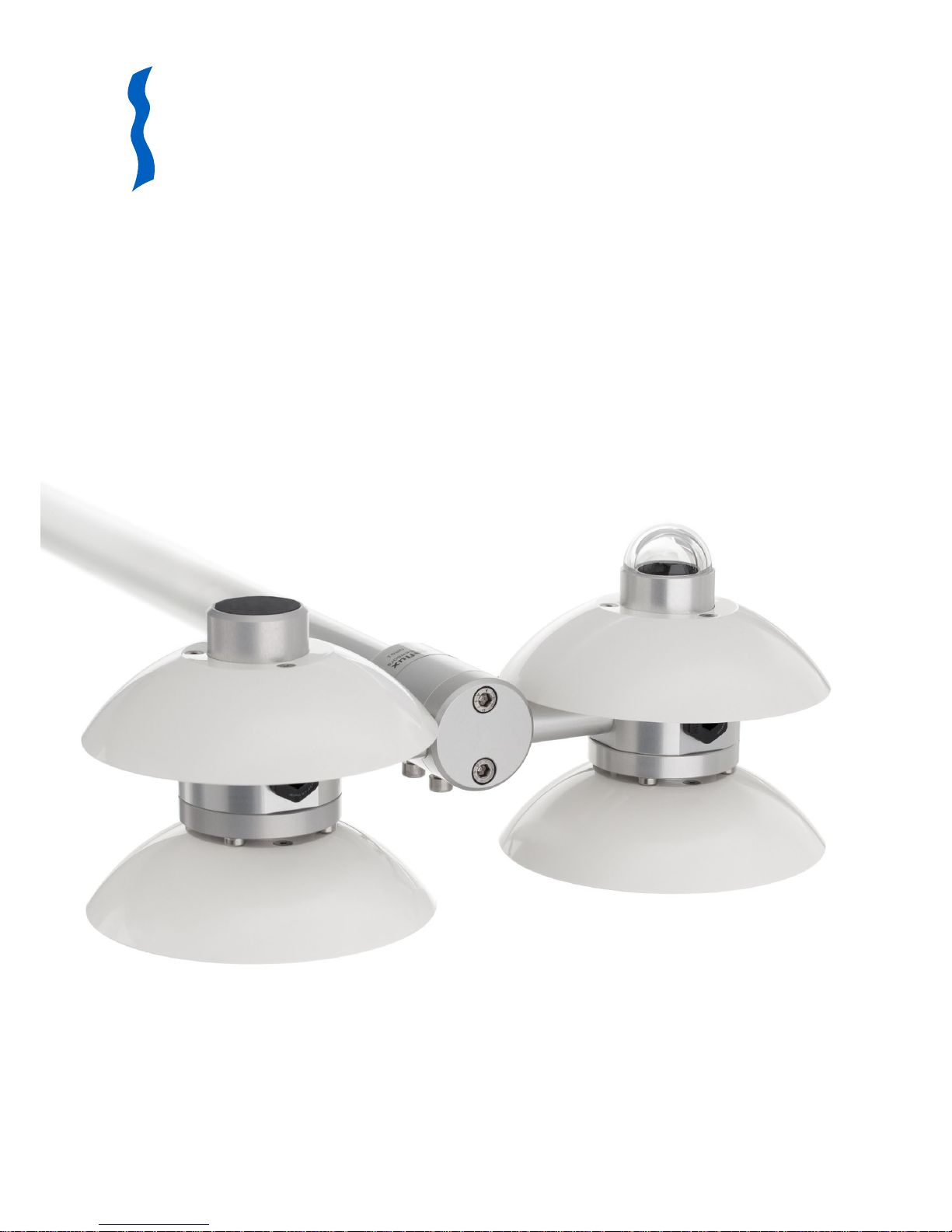
USER MANUAL NR01 / RA01
NR01 4-component net radiometer
RA01 2-component radiometer
Hukseflux
Thermal Sensors
Page 2
NR01 RA01 manual v1710 2/71
Warning statements
Putting more than 12 Volt across the sensor wiring
can lead to permanent damage to the sensor.
Do not use “open circuit detection” when measuring
the sensor outputs.
Page 3

NR01 RA01 manual v1710 3/71
Contents
Warning stat em e nts 2
Contents 3
List of symbols 5
Introduction 6
1 Ordering and checking at delivery 9
1.1 Ordering NR01 9
1.2 Included items 9
1.3 Quick instrument check 10
2 Instrument principle and theory 12
2.1 General 12
2.2 Pyranometers model SR01 15
2.3 Pyrgeometers model IR01 16
2.4 Typical measurement results 18
2.5 Optional heating 19
3 Specifications of NR01 20
3.1 Specifications of NR01 20
3.2 Specifications of pyranometer SR01 23
3.3 Specifications of pyrgeometer IR02 24
3.4 Dimensions of NR01 26
4 Standards and recommended practices for use 27
4.1 Classification standard for pyranometers and pyrradiometers 27
4.2 General use for net radiation measurement 28
4.3 General use for sunshine duration measurement 28
4.4 Specific use in meteorology and climatology 29
5 Installation of NR01 30
5.1 Site selection and installation 30
5.2 Installation of the sun screens 31
5.3 Mounting NR01 on a tube 31
5.4 Electrical connection of NR01 32
5.5 Requirements for data acquisition / amplification 34
6 Making a dependable measureme nt 35
6.1 The concept of dependability 35
6.2 Reliability of the measurement 36
6.3 Repair and maintenance 37
6.4 Uncertainty evaluation 37
7 Maintenance and trouble shooting 41
7.1 Recommended maintenance and quality assurance 41
7.2 Trouble shooting 42
7.3 Calibration and checks in the field 45
7.4 Data quality assurance 47
8 RA01 2-component radiometer 48
8.1 Introduction RA01 48
8.2 Specifications of RA01 49
8.3 Dimensions of RA01 52
8.4 Electrical connection of RA01 55
9 Appendices 57
9.1 Appendix on cable extension / replacement 57
9.2 Appendix on tools for NR01 58
9.3 Appendix on spare parts for NR01 58
Page 4

NR01 RA01 manual v1710 4/71
9.4 Appendix on standards for classification and calibration 59
9.5 Appendix on calibration hierarchy 60
9.6 Appendix on meteorological radiation quantities 63
9.7 Appendix on ISO and WMO classification tables 64
9.8 Appendix on definition of pyranometer specifications 65
9.9 Appendix on terminology / glossary 66
9.10 Appendix on older NR01 models 68
9.11 EU declaration of conformity 69
Page 5

NR01 RA01 manual v1710 5/71
List of symbols
Quantities Symbol Unit
Voltage output U V
Sensitivity S V/(W/m
2
)
Temperature T °C
Longwave and solar irradiance E W/m
2
Stefan–Boltzmann constant (5.67 x 10
-8
) σ W/(m2∙K4)
Sunshine duration SD h
(see also appendix 9.6 on meteorological quantities)
Subscripts
sky relating to the atmosphere
surface relating to the ground surface
ambient relating to ambient air
body relating to the instrument body
sensor relating to the sensor
Page 6

NR01 RA01 manual v1710 6/71
Introduction
NR01 is a market leading 4-component net radiation sensor, mostly used in scientificgrade energy balance and surface flux studies. It offers 4 separate measurements of
global and reflected solar and downwelling and upwelling longwave radiation, using 2
sensors facing up and 2 facing down. NR01 owes its popularity to its excellent price /
performance ratio. Advantages include its modular design, low weight, ease of levelling,
and low solar offsets in the longwave measurement. The unique capability to heat the
pyrgeometers reduces measurement errors caused by dew deposition.
NR01 measures the 4 separate components of the surface radiation balance: downward
and upward solar and longwave radiation. The solar radiation sensors are called
pyranometers and the longwave sensors are called pyrgeometers. From these 4 separate
components the net radiation is derived. For calculation of sky- and surface
temperatures, it is necessary to compensate for irradiated heat by the pyrgeometers
themselves (Stefan-Boltzmann law). A Pt100 temperature sensor is included in NR01’s
body for that purpose. Sunshine duration may be estimated according to the WMO
approved pyranometric method.
The solar irradiance is measured by pyranometers model SR01, the longwave radiation is
measured by pyrgeometers model IR01.
In order to prevent condensation of water on the pyrgeometer windows the NR01 has
internal heating close to the pyrgeometers. This keeps the instrument above dew point.
As water blocks longwave radiation, heating will improve the reliability of longwave
radiation measurement, in particular at night, when the risk of condensation is highest.
Solar offsets in the longwave radiation measurement are very low. Features like these
have made NR01 net radiometers popular in energy balance and surface flux studies. In
addition, NR01 net radiometer is practical to mount; it is much lighter than competing
models and a 2-axis levelling assembly is included. The levelling assembly fits a 1 inch
NPS tube (the tube’s recommended outer diameter equals 33.4 x 10
-3
m). With the NR01
shim, included in NR01’s delivery, a ¾ inch NPS tube may also be used.
Using NR01 net radiometer is easy. It can be connected directly to commonly used data
logging systems. The irradiance levels in W/m
2
are calculated by dividing the NR01
outputs, small voltages, by the sensitivities. The longwave irradiance should be corrected
using the instrument body temperature. The sensitivities of all sensors are provided with
NR01 on its product certificate.
NR01 net radiometer has a modular design: it is possible to take the instrument apart
and replace or re-calibrate individual sensors. For this reason it is often selected for use
in large monitoring networks.
Suggested use for NR01:
• energy balance studies
• surface flux measurements
• climatological networks
Page 7
NR01 RA01 manual v1710 7/71
The solar irradiance in W/m2 is calculated by dividing the SR01 output, a small voltage,
by the sensitivity. The sensitivity is provided with SR01 on its calibration certificate.
The central measurement equation governing solar radiation measurement with
pyranometers is:
E = U/S (Formula 0.1)
The longwave irradiance in W/m
2
is calculated by dividing the IR01 output, a small
voltage, by the sensitivity and taking in account the irradiated heat by the sensor itself
(Stefan-Boltzmann law). The sensitivity is provided with IR01 on its calibration
certificate.
The central measurement equation governing longwave measurement with pyrgeometers
is:
E = U/S + σ·(T + 273.15)
4
(Formula 0.2)
From the upward and downward solar radiation, it is possible to calculate net solar
radiation and albedo or surface reflectance. From all 4 solar and longwave components,
the net radiation, sky temperature and surface temperature can be derived.
The instrument should be used in accordance with the recommended practices of ISO,
WMO and ASTM.
Applicable instrument-classification standards are ISO 9060 and WMO-No. 8; Guide to
Meteorological Instruments and Methods of Observation.
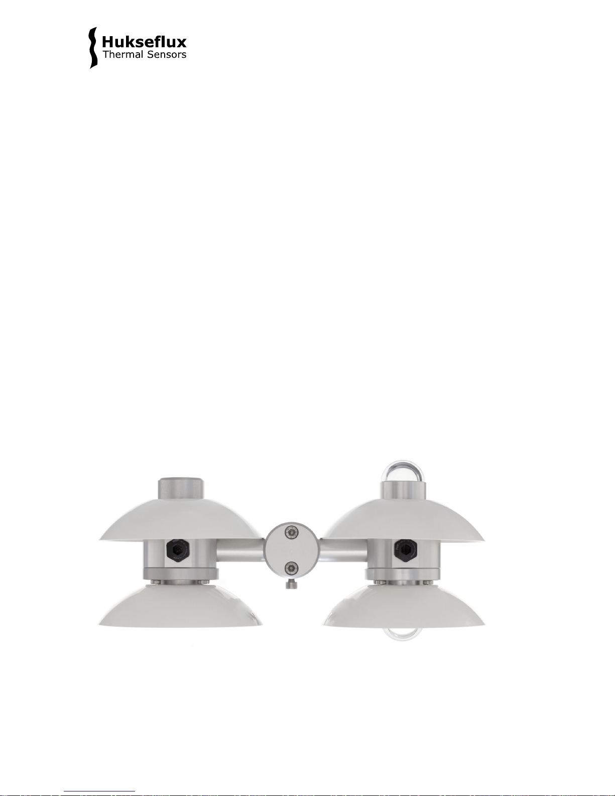
Figure 0.1 NR01 4-component net radiometer
Page 8
NR01 RA01 manual v1710 8/71
RA01 is a single-sided version of NR01. It measures the 2 incoming components of the
surface radiation balance; global solar and downward longwave radiation. RA01 is used
for estimating (not measuring) net radiation, in particular when local surface properties
are not representative, or if system costs need to be reduced. However, when using
RA01 for net radiation estimates, the reflected solar radiation or albedo and the surface
temperature or upwards longwave radiation must be estimated by the user.
This manual is written for NR01 4-component net radiometer. For RA01
2-component radiometer please consult the dedicated RA01 chapter.
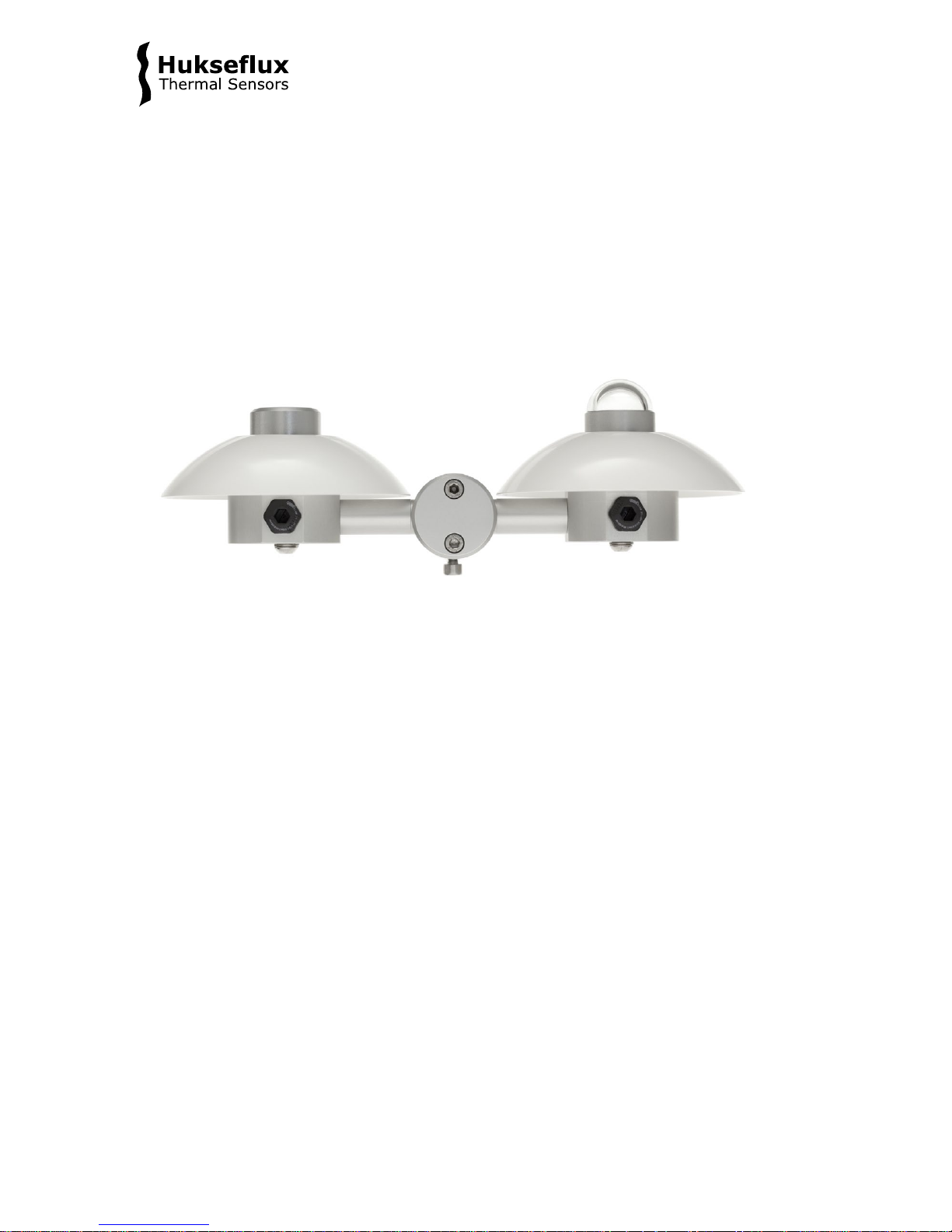
Figure 0.2 RA01 2-component radiometer
Page 9

NR01 RA01 manual v1710 9/71
1 Ordering and checking at delivery
1.1 Ordering NR01
The standard configuration of NR01 is with two cables, each of 5 metres.
Common options are:
• Longer cables (in multiples of 5 m). Specify total cable length. (cable lengths above
20 m in multiples of 10 m)
• Internal temperature sensor. This can be either a Pt100 (standard configuration) or a
10 kΩ thermistor (optional). Specify respectively T1 or T2.
1.2 Included items
Arriving at the customer, the delivery should include:
• NR01 4-component net radiometer, including a 2-axis levelling assembly
• cable of the length as ordered
• including 4 sun screens
• 1 x product certificate matching the instrument serial number, including
4 x calibration certificate of the sensors
• 1 x hex key (2 mm) for fixation and removal of sun screens
• 1 x shim for optionally mounting NR01 on a ¾ inch NPS tube instead of on a 1 inch
NPS tube (tubes are not included)
Please store the certificates in a safe place.
Page 10

NR01 RA01 manual v1710 10/71
1.3 Quick instrument check
For checking the instrument see the wiring diagram on the product certificate or in the
chapter on electrical connection of this manual.
1.3.1 General check
1. Inspect the instrument for any damage.
2. remove the sun screens, using the hex key (see chapter on installation of the sun
screen). Inspect the bubble levels.
3. check the instrument serial numbers against the certificates supplied with the
instrument.
4. check the levelling assembly for x- and y-axis by unlocking the 4 x hex bolts for
levelling adjustment.
1.3.2 Check of pyranometers SR01
A quick test of the instrument can be done by using a simple hand held multimeter and a
lamp.
1. Check the electrical resistance of the sensor between the minus (-) and plus (+) wire.
Use a multimeter at the 200 Ω range. Measure the sensor resistance first with one
polarity, than reverse the polarity. Take the average value. The typical resistance of the
wiring is 0.1 Ω/m. Typical resistance should be the typical sensor resistance of 40 to 60
Ω plus 1.5 Ω for the total resistance of two wires (back and forth) of each 5 m. Infinite
resistance indicates a broken circuit; zero or a low resistance indicates a short circuit.
2. Check if the sensor reacts to light: put the multimeter at its most sensitive range of
DC voltage measurement, typically the 100 x 10
-3
VDC range or lower. Expose the sensor
to a strong light source, for instance a 100 W light bulb at 0.1 m distance. The signal
should read > 2 x 10
-3
V now. Darken the sensor either by putting something over it or
switching off the light. The instrument voltage output should go down and within one
minute approach 0 V.
1.3.3 Check of pyrgeometers IR01
A quick test of the instrument can be done by using a simple hand held multimeter and a
thermal source.
1. Check the electrical resistance of the sensor between the minus (-) and plus (+) wire.
Use a multimeter at the 1000 Ω range. Measure the sensor resistance first with one
polarity, than reverse the polarity. Take the average value. The typical resistance of the
wiring is 0.1 Ω/m. Typical resistance should be the typical sensor resistance of 100 to
400 Ω plus 1.5 Ω for the total resistance of two wires (back and forth) of each 5 m.
Infinite resistance indicates a broken circuit; zero or a low resistance indicates a short
circuit.
2. Check if the sensor reacts to heat: put the multimeter at its most sensitive range of
DC voltage measurement, typically the 100 x 10
-3
VDC range or lower. Make sure that
the sensor is at 25 °C or lower. Expose the sensor to a heat source at a short distance
from the window of more than 50 °C, for instance a heavy (> 5 kg) painted block of
Page 11

NR01 RA01 manual v1710 11/71
metal, or a painted metal container holding hot water. Face the side of the container to
avoid condensation of water on the pyrgeometer window. Stir the water to attain
homogeneity. A painted surface will act as a blackbody in the far-infra-red (FIR),
irrespective of the visible colour. The signal should read positive and > 1 x 10
-3
V now. In
case of using your hand as a heat source, the signal should be significantly lower.
1.3.4 Check of the Pt100
1. Check the electrical resistance of the Pt100. The resistance between 2 wires at
opposite ends of the Pt100 should be in the 100 Ω range.
2. Check the electrical resistance of the Pt100. The resistance between 2 wires at the
same end of the Pt100 should be in the 10 Ω range or 0.1 Ohm per metre cable.
1.3.5 Check of the heater
1. Check the electrical resistance of the heater. This should be in the 100 Ω range.
1.3.6 Optional check for trouble shooting: short circuit check
1. Check the electrical resistance between the sensor wires of different sensors; this
should be higher than 1 x 10
6
Ω. Most multimeters cannot measure in this range, so
please use the highest range. Also check between sensors and heater and between
sensors and Pt100. Check the resistance between sensors and body.
Page 12

NR01 RA01 manual v1710 12/71
2 Instrument principle and theory
2.1 General
NR01 is a 4-component net-radiometer, consisting of 2 pyranometers type SR01, 2
pyrgeometers type IR01, a heater, levelling assembly for x- and y-axis and a Pt100
instrument body temperature sensor. The design is fully modular, which is easy for
servicing and calibration. This chapter describes the instrument measuring principle and
theory.
Pyranometers and pyrgeometers (the latter with additional input of the body temperature
measurement) measure the solar and longwave radiation received by a plane surface, in
W/m
2
. The most common application of NR01 is measurement of net radiation.
From the 4 individual components measured by NR01, the net radiation and several
other measurands are calculated.
The following equations apply.
For terminology: see also the appendix on meteorological radiation quantities.
For the upfacing and downfacing pyranometers, global and reflected solar radiation:
E
g
↓ h = U/S (Formula 2.1.1)
E
r
↑ = U/S (Formula 2.1.2)
For the upfacing and downfacing pyrgeometers downward and upward longwave
irradiance:
E
l
↓ = U/S + σ·(T + 273.15)4 (Formula 2.1.3)
E
l
↑ = U/S + σ·(T + 273.15)4 (Formula 2.1.4)
Net radiation and albedo (please note that in the calculation of the net radiation, the
instrument temperature measurement is no longer included):
E* = E ↓ – E ↑ = E
g
↓ h - Er ↑ + El ↓ - El ↑ (Formula 2.1.5)
Albedo = E
r
↑ / Eg ↓ h (Formula 2.1.6)
Equivalent blackbody temperatures of the surface and sky:
T
surface
= (El ↑/σ)
1/4
- 273.15 (Formula 2.1.7)
T
sky
= (El ↓/σ)
1/4
- 273.15 (Formula 2.1.8)
Page 13
NR01 RA01 manual v1710 13/71
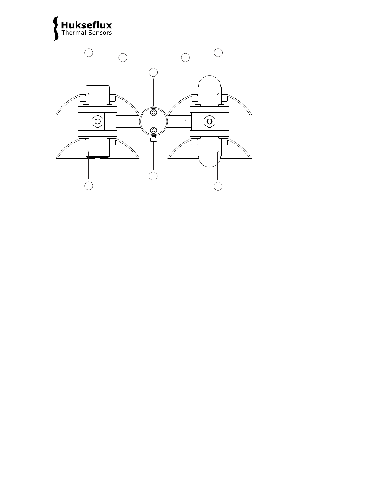
Figure 2.1.1 Overview of NR01:
(1) upfacing pyrgeometer model IR01
(2) sun screens
(3,4) levelling assembly for x- and y-axis
(5) upfacing pyranometer model SR01
(6) downfacing pyranometer model IR01
(7) 4 x hex bolts for levelling adjustment
(8) downfacing pyrgeometer model IR02
1
2
3
4
5
6
7
8
Page 14
NR01 RA01 manual v1710 14/71
1
2
32
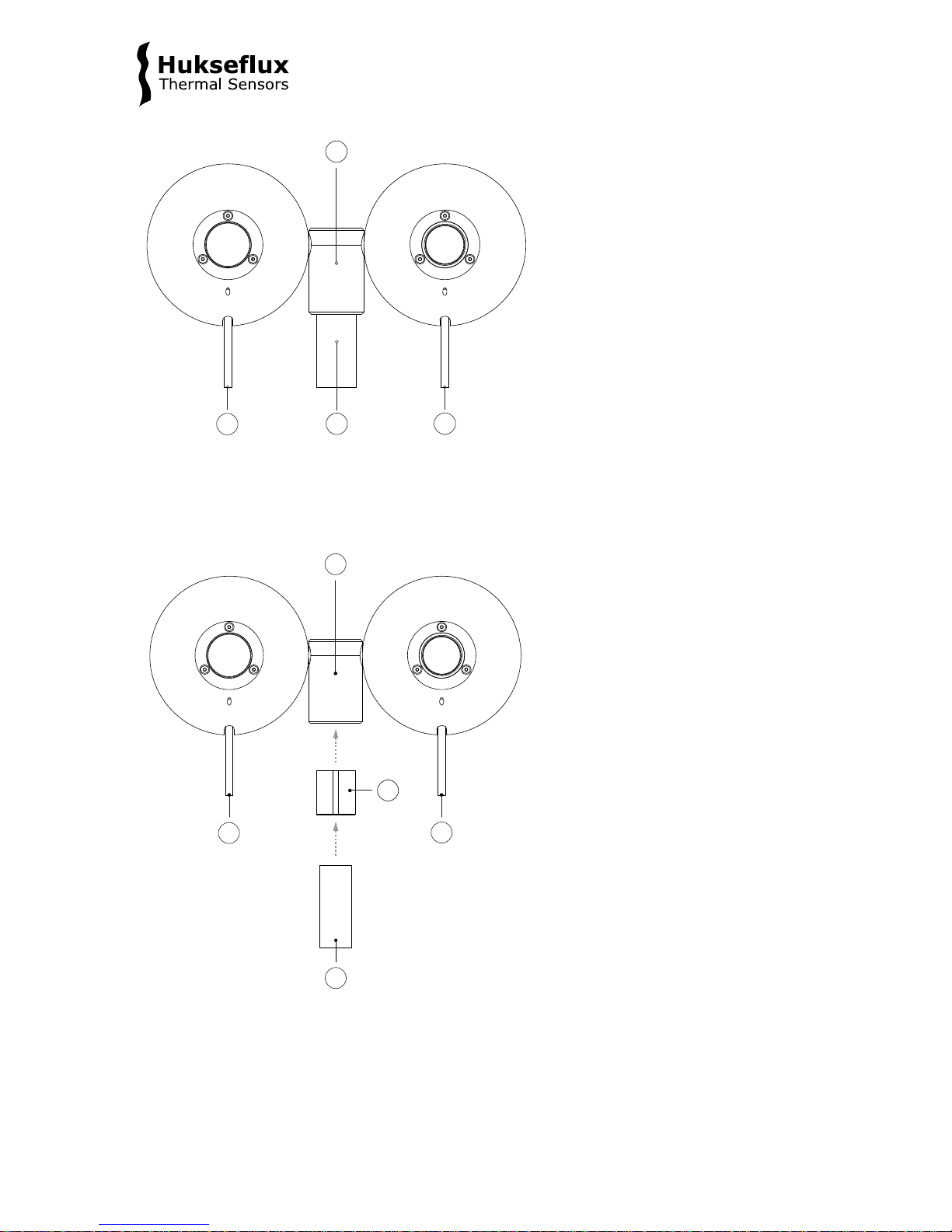
Figure 2.1.2 Top view of NR 01 fitting a 1 inch NPS tube:
(1) levelling assembly for x- and y-axis
(2) cable (cable 1 at the left, at pyranometer side, cable 2 at the right, at pyrgeometer side)
(3) 1 inch NPS mounting tube (not included)
Figure 2.1.3 Top view of NR01 fitting a ¾ inch NPS tube (alternative mounting method):
(1) levelling assembly for x- and y-axis
(2) cable (cable 1 at the left, at pyranometer side, cable 2 at the right, at pyrgeometer side)
(3) ¾ inch NPS mounting tube (not included)
(4) shim, included with NR01 delivery
1
2
3
2
4
Page 15

NR01 RA01 manual v1710 15/71
2.2 Pyranometers model SR01
SR01’s scientific name is pyranometer. A pyranometer measures the solar radiation
received by a plane surface from a 180° field of view angle. This quantity, expressed in
W/m
2
, is called “hemispherical” solar radiation. NR01 typically is mounted horizontally.
Measuring in the horizontal plane, downward solar radiation is called global solar
radiation, upward solar radiation is called reflected solar radiation. The solar radiation
spectrum extends roughly from 285 to 3000 x 10
-9
m. By definition a pyranometer
should cover that spectral range with a spectral selectivity that is as “flat” as possible.
In an irradiance measurement by definition the response to “beam” radiation varies with
the cosine of the angle of incidence; i.e. it should have full response when the solar
radiation hits the sensor perpendicularly (normal to the surface, sun at zenith, 0 ° angle
of incidence), zero response when the sun is at the horizon (90 ° angle of incidence, 90 °
zenith angle), and 50 % of full response at 60 ° angle of incidence.
A pyranometer should have a so-called “directional response” (older documents mention
“cosine response”) that is as close as possible to the ideal cosine characteristic.
In order to attain the proper directional and spectral characteristics, a pyranometer’s
main components are:
• a thermal sensor with black coating. It has a flat spectrum covering the 200 to 50000
x 10
-9
m range, and has a near-perfect directional response. The coating absorbs all
solar radiation and, at the moment of absorption, converts it to heat. The heat flows
through the sensor to the sensor body. The thermopile sensor generates a voltage
output signal that is proportional to the solar irradiance.
• a glass dome. This dome limits the spectral range from 285 to 3000 x 10
-9
m (cutting
off the part above 3000 x 10
-9
m), while preserving the 180° field of view angle.
Another function of the dome is that it shields the thermopile sensor from the
environment (convection, rain).
Pyranometers can be manufactured to different specifications and with different levels of
verification and characterisation during production. The ISO 9060 - 1990 standard, “Solar
energy - specification and classification of instruments for measuring hemispherical solar
and direct solar radiation”, distinguishes between 3 classes; secondary standard (highest
accuracy), first class (second highest accuracy) and second class (third highest
accuracy). SR01 is a second-class pyranometer.
Page 16
NR01 RA01 manual v1710 16/71
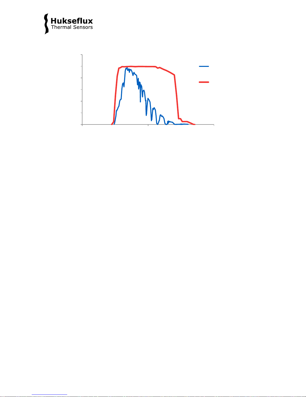
Figure 2.2.1 Spectral response of the pyranometer compared to the solar spectrum. The
pyranometer on l y cuts off a negligible part of the total solar spectrum.
2.3 Pyrgeometers model IR01
IR01’s scientific name is pyrgeometer. IR01 measures the longwave or far-infra-red (FIR)
radiation received by a plane surface, in W/m
2
, ideally from a 180 ° field of view angle.
In meteorological terms pyrgeometers are used to measure “downward and upward
longwave irradiance” (WMO definition). In case of IR01 the ideal 180 ° field of view angle
has been reduced to 150 °. This makes it possible to offer an instrument at an attractive
price level, while the loss of accuracy is relatively small.
As secondary measurands, the sky temperature T
sky
, and the equivalent surface (ground)
temperature T
surface
can be measured. Both are so-called equivalent blackbody radiative
temperatures, i.e. temperatures calculated from the pyrgeometer measurement
assuming these are uniform-temperature blackbodies with an emission coefficient of 1.
Longwave radiation is the part of the radiation budget that is not emitted by the sun. The
spectral range of the longwave radiation is not standardised. A practical cut-on is in the
range of 4 to 5 x 10
-6
m (see figure 2.3.1).
In the longwave spectrum, the sky can be seen as a temperature source; colder than
ground level ambient air temperature, with its lowest temperatures at zenith, getting
warmer (closer to ambient air temperature) at the horizon. The uniformity of this
longwave source is much better than that in the range of the solar spectrum, where the
sun is a dominant contributor. The “equivalent blackbody” temperature, as a function of
zenith angle, roughly follows the same pattern independent of the exact sky condition
(cloudy or clear). This explains why for pyrgeometers the directional response is not very
critical.
0
0,2
0,4
0,6
0,8
1
1,2
100 1000 10000
relative spectral content /
response [arbitrary units]
wavelength [x 10
-9
m]
solar radiation
pyranometer
response
Page 17
NR01 RA01 manual v1710 17/71
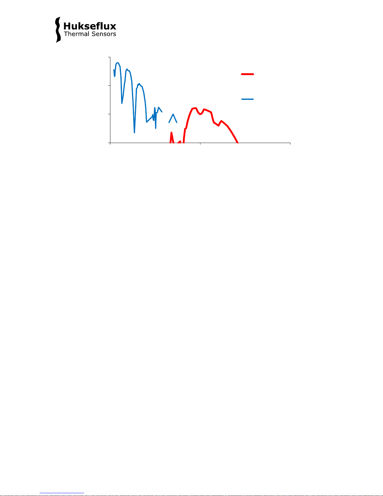
Figure 2.3.1 Atmospheric radiation as a function of wavelength plotted along two
logarithmic axes to highlight the longwave radiation. Longwave radiation is mainly
present in the 4 to 50 x 10
-6
m range, whereas solar radiation is mainly present in the
0.3 to 3 x 10
-6
m range. In practice, the two are measured separately using
pyrgeometers and pyranometers
The downwelling longwave radiation essentially consists of several components:
1. low temperature radiation from the universe, filtered by the atmosphere. The
atmosphere is transparent for this radiation in the so-called atmospheric window (roughly
the 10 to 15 x 10
-6
m wavelength range).
2. higher temperature radiation emitted by atmospheric gasses and aerosols.
3. in presence of clouds or mist, the low temperature radiation from the universe is
almost completely blocked by the water droplets. The pyrgeometer then receives the
radiation emitted by the water droplets.
Upwelling longwave irradiance is measured with downfacing instruments. These are
presumably looking directly at the surface (absorption and emission of the atmosphere is
low over a short distance of around 2 m), which behaves like a normal blackbody.
0,001
0,010
0,100
1,000
1 10 100
spectral irradiance
[x 10
-9
W/(m
2
/m)]
wavelength [x 10-6 m]
downwelling
longwave
solar
Page 18

NR01 RA01 manual v1710 18/71
2.4 Typical measurement results
2.4.1 Pyranometer measurement results
Pyranometers theoretically only generate an output when the sun is in their field of view;
i.e, when the sun is above the horizon.
The extraterrestial global solar irradiance (GHI) can serve as the expected range limit to
the local global solar irradiance. This range limit depends depends on time of day,
coordinates and daynumber. Lower values than the range limit will be measured
depending on the local weather. Under some circumstances values may exceed the range
limit, for instance when there is reflection against large cumulus clouds or snow-covered
mountain slopes. Under these circumstances even the extraterrestial solar direct normal
irradiance or solar constant E
0
of around 1350 W/m2 may be exceeded.
Reflected solar irradiance depends largely on the incoming GHI and surface properties.
The study of albedo versus time offers a good method of quality assurance. In case of
constant surface properties, the albedo over the day should not vary very much below
solar zenith angles of 60°. Also in case of constant surface properties the albedo should
show consistent patterns over the day from one day to the next.
The upfacing pyranometer may generate a negative signal at night, as specified by “zero
offset a”. For SR01 the specification is < 15 W/m
2
(unventilated).
2.4.2 Pyrgeometer measurement results
Pyrgeometers generate an output both during daytime and during nighttime.
Please note that the output generated by an upfacing pyrgeometer usually has a
negative sign.
The most important factors determining downward longwave irradiance are:
• ambient air temperature
• sky condition / cloud cover
• atmospheric moisture content
The largest errors in measurement of downward longwave irradiance are made during
clear nights when dew is deposited on the instrument. In that case the output rises from
a large negative value, in the order of of – 100 W/m
2
(the correct value) to 0 W/m2 (an
incorrect value and a large error). The daytime measurement of downward longwave
may contain a solar offset as specified under “solar offset” as < 15 W/m
2
at 1000 W/m2
solar irradiance.
Page 19
NR01 RA01 manual v1710 19/71
Table 2.4.2.1 Expected pyrgeometer output U/S for an upfacing pyrgeometer at
different ambient air temperatures, T
ambient
, and at different cloud conditions. Under clear
sky conditions the U/S is around -100 W/m
2
while under cloudy conditions it will be close
to 0 W/m
2
. Also calculated: the sky temperature, T
sky
, and the downward longwave
irradiance E
l
↓.
EXPECTED PYRGEOMETER OUTPUT DOWNWARD LONGWAVE IRRADIANCE
T
ambient
Sky condition U/S T
sky
El ↓
[°C]
[cloudy], [clear]
[W/m2]
[°C]
[W/m2]
-20
cloudy
0
-20
232
-20
clear sky
-100
-53
132 0 cloudy
0
0
314
0 clear sky -100 -24 214
+30
cloudy
0
+30
477
+30 clear sky -100 +12 377
A downfacing pyrgeometer will typically generate a voltage output signal very close to
zero. The ground surface temperature usually is very close to the instrument
temperature, so that the radiative exchange between instrument and surface is low.
Table 2.4.2.2 Expected pyrgeometer output U/S for an downfacing pyrgeometer at
different ambient air temperatures, T
ambient
, and at different cloud conditions. Under clear
sky conditions as well as under cloudy conditions it will be close to 0 W/m
2
. Also
calculated: the surface temperature, T
surface
, and the upward longwave irradiance El ↑
EXPECTED PYRGEOMETER OUTPUT UPWARD L ON G W AVE I R RADIANCE
T
ambient
Sky condition U/S T
surface
El ↑
[°C]
[cloudy], [clear]
[W/m2]
[°C]
[W/m2]
-20
cloudy
0
-20
232
-20
clear sky
0
-20
232
0
cloudy
0
0
314
0
clear sky
0
0
314
+30
cloudy
0
+30
477
+30 clear sky 0 +30 477
2.5 Optional heating
A low-power heater is located in the body of the net radiometer at the pyrgeometer side.
The heater is not necessarily switched on; recommended operation is to activate the
heater when there is a risk of dew deposition. In case power is available, many users
choose to keep the heater continuously on.
Page 20
NR01 RA01 manual v1710 20/71
3 Specifications of NR01
3.1 Specifications of NR01
NR01 is a 4-component net radiometer, consisting of 2 pyranometers type SR01, 2
pyrgeometers type IR01, a heater, levelling assembly for x- and y-axis and a Pt100
instrument body temperature sensor.
Pyranometers and pyrgeometers (the latter with additional input of the body temperature
measurement) measure the solar and longwave radiation received by a plane surface, in
W/m
2
. For compensation of pyrgeometer emission in the longwave calculation and for
calculation of sky- and surface temperature, a Pt100 temperature sensor is included in
the instrument body. Working completely passive, using a thermopile sensor, the sensors
generate a small output voltage proportional to these fluxes. Optional measurands
include solar albedo and sunshine duration. NR01 can only be used in combination with a
suitable measuring system. The instrument should be used in accordance with the
recommended practices of ISO, IEC, WMO and ASTM.
Table 3.1.1 Specifications of NR01 (continued on next pages)
NR01 GENERAL SPECIFICATIONS
Product type
4-component net radiometer
Included sensors 2 x identical ISO 9060 second class pyranometer
(see separate specification table for model SR01)
2 x identical pyrgeometer with 150 ° field of view
angle
(see separate specification table for model IR01)
Spectral range solar
285 to 3000 x 10-9 m
Spectral range longwave
4.5 to 40 x 10-6 m
Levelling
Bubble level and a levelling assembly for x- and yaxis are included
Required sensor power
zero (passive sensor)
Temperature sensor
Pt100
Heater on pyrgeometer
12 VDC, 1.5 W (see below for details)
Rated operating temperature range
-40 to +80 °C
Rated operating relative humidity range
0 to 100 %
Required readout 4 x differential voltage channel or 4 x single ended
voltage channel, input resistance > 10
6
Ω
1 x temperature channel for Pt100
Standards governing use of the
instrument
ISO/TR 9901:1990 Solar energy -- Field
pyranometers -- Recommended practice for use
ASTM G183 - 05 Standard Practice for Field Use of
Pyranometers, Pyrheliometers and UV Radiometers
WMO-No. 8, Guide to Meteorological Instruments and
Methods of Observation, seventh edition 2008,
paragraph 7.4 "measurement of total and long-wave
radiation"
Page 21

NR01 RA01 manual v1710 21/71
Table 3.1.1 Specifications of NR01 (continued)
NR01 MEASURANDS
Measurand all 4 radiometers
net radiation
Measurand in SI units
irradiance in W/m2
Measurement function / required
programming net radiation
E* = E ↓ – E ↑ = Eg ↓
h - Er
↑ + El ↓ - El ↑
Measurand upfacing pyranometer
global solar radiation
Measurand in SI units
irradiance in W/m2
Measurement function / required
programming global solar irradiance
Eg ↓ h = U/S
Measurand downfacing pyranometer
reflected solar radiation
Measurand in SI units
irradiance in W/m2
Measurement function / required
programming reflected solar irradiance
E
r
↑
= U/S
Measurand upfacing pyrgeometer
downward longwave radiation*
Measurand in SI units
irradiance in W/m2
Measurement function / required
programming downward longwave
radiation
El ↓ = U/S + σ·(T + 273.15)4
Measurand downfacing pyrgeometer
upward longwave radiation*
Measurands in SI units
irradiance in W/m2
Measurement function / required
programming upward longwave irradiance
El ↑ = U/S + σ·(T + 273.15)4
Optional measurand downfacing
pyrgeometer
surface temperature*
Optional measurand in SI units
equivalent blackbody radiative temperature in °C
Measurement function / required
programming surface temperature
T
surface
= (El ↑/σ)
1/4
- 273.15
Optional measurand upfacing
pyrgeometer
sky temperature*
Optional measurand in SI units
equivalent blackbody radiative temperature in °C
Measurement function / required
programming sky temperature
T
sky
= (El ↓/σ)
1/4
- 273.15
Optional measurand pyranometers
albedo or solar reflectance
Optional measurand in SI units
albedo or solar reflectance in (W/m2)/(W/m2)
Measurement function / required
programming albedo
albedo = solar reflectance = E
r
↑
/ Eg ↓ h
Optional measurand upfacing pyranomete
sunshine duration
Optional measurand in SI units
sunshine duration in h
Measurement function / optional
programming sunshine duration
according to WMO guide paragraph 8.2.2
Measurand Pt100
instrument body temperature T
body
Measurand in SI units
temperature in ° C
*required measurand: instrument body temperature.
Page 22

NR01 RA01 manual v1710 22/71
Table 3.1.1 Specifications of NR01 (continued)
NR01 MOUNTING, CABLING, TRANSPORT
Standard cable length (see options)
2 x 5 m
Cable diameter
5.3 x 10⁻³ m
Cable replacement cable can be removed and installed by the user
provided that the cable is sealed at the instrument
side against humidity ingress. Consult Hukseflux for
instructions or use Hukseflux-supplied parts.
Instrument mounting a levelling assembly for x- and y-axis is included. It
fits a 1 inch NPS tube (the tube’s recommended outer
diameter equals 33.4 x 10⁻³ m). Attach mounting tube
to levelling assembly using a a hex key size 4.0 mm
(not included) for bolt size M5. With the NR01 shim,
included in NR01’s delivery, a ¾ inch NPS tube may
also be used. This tube’s recommended outer diameter
equals 26.8 x 10⁻³ m. Tubes are not included.
Levelling accuracy
< 0.6 ° bubble entirely in ring
IP protection class
IP67
Gross weight including 2 x 5 m cable
2.05 kg
Net weight including 2 x 5 m cable
1.35 kg
Packaging
box of (330 x 250 x 220) mm
HEATING
Heater operation the heater is not necessarily switched on;
recommended operation is to activate the heater
when there is a risk of dew deposition
Required heater power
1.5 W at 12 VDC. (The heater is not necessarily active)
Heater resistance
95 Ω
CALIBRATION
Calibration traceability solar
to WRR (see SR01 for details)
Calibration traceability longwave
to WISG (see IR01 for details)
Calibration traceability Pt100
to ITS-90
Validity of calibration
based on experience the instrument sensitivity will not
change during storage. During use under exposure to
solar radiation the instrument “non-stability”
specification is applicable.
Recommended recalibration interval
2 years
MEASUREMENT ACCURACY
Uncertainty of the measurement
statements about the overall measurement
uncertainty can only be made on an individual basis.
See the chapter on uncertainty evaluation
Temperature sensor accuracy class
Pt100 DIN EN 60751 class A
Uncertainty Pt100
± (0.15 °C + 0.002·|T|)
WMO ESTIMATE OF ACHIEVABLE MEASUREMENT UNCERTAINTY
Achievable measurement accuracy for daily
sums of net radiation, E*, according to
WMO under nominal and recommended
exposure (WMO guide annex 1.B)
± 0.4 x 10⁶ J/m2 for < 8 x 10⁶ J/m2
± 5 % for > 8 x 10
6
J/m
2
see also SR01 and IR01 specifications
VERSIONS / OPTIONS
longer cable, in multiples of 5 m, cable
lengths above 20 m in multiples of 10 m
option code = total cable length
Internal temperature sensor
measuring the instrument body temperature:
version code = T1 for Pt100 DIN class A,
version code = T2 for thermistor 10 kΩ at 25 °C
Page 23

NR01 RA01 manual v1710 23/71
3.2 Specifications of pyranometer SR01
SR01 pyranometer measures the solar radiation received by a plane surface from a from
a 180
o
field of view angle. This quantity, expressed in W/m2, is called “hemispherical”
solar radiation. NR01, in which 2 x SR01 are incorporated, is typically mounted
horizontally. Measuring in the horizontal plane, downward solar radiation is called global
solar radiation, upward solar radiation is called reflected solar radiation. Working
completely passive, using a thermopile sensor, SR01 generates a small output voltage
proportional to this flux. It can only be used in combination with a suitable measurement
system. The instrument is classified according to ISO 9060 and should be used in
accordance with the recommended practices of ISO, IEC, WMO and ASTM.
Table 3.2.1 Specifi ca t i on s of SR01 (continued on next page)
SR01 PYRANOMETER MEASUREMENT SP ECIFICATIONS:
LIST OF CLASSIFICATION CRITERIA OF ISO 9060*
ISO classification (ISO 9060: 1990)
second class pyranometer
WMO performance level (WMO-No-8,
seventh edition 2008)
moderate quality pyranometer
Response time (95 %)
18 s
Zero offset a (response to 200 W/m2
net thermal radiation)
< ± 15 W/m
2
unventilated
Zero offset b (response to 5 K/h
change in ambient temperature)
< ± 4 W/m2
Non-stability
< ± 1 % change per year
Non-linearity
< ± 1 % (100 to 1000 W/m2)
Directional response
< ± 25 W/m2
Spectral selectivity
< ± 5 % (0.35 to 1.5 x 10
-6
m)
Temperature response
< ± 3 % (-10 to +40 °C)
Tilt response
< ± 2 % (0 to 90 ° at 1000 W/m2)
*For the exact definition of pyranometer ISO 9060 specifications see the appendix.
Page 24

NR01 RA01 manual v1710 24/71
Table 3.2.1 Specifications of SR01 (continued)
SR01 PYRANOMETER ADDITIONAL SPECIFICATIONS
Measurand
global and reflected solar radiation
Measurand in SI radiometry units
irradiance in W/m2
Field of view angle
180 °
Measurement range
0 to 2000 W/m-2
Sensitivity range
7 to 25 x 10-6 V/(W/m2)
Sensitivity (nominal)
15 x 10-6 V/(W/m2)
Expected voltage output
application under natural solar radiation: -0.1 to + 50
x 10-6 V
Measurement function / required
programming
E = U/S
Sensor resistance range
40 to 60 Ω
Required sensor power
zero (passive sensor)
Spectral range (20 % transmission
points)
285 to 3000 x 10-9 m
CALIBRATION
Calibration traceability
to WRR
Calibration hierarchy
from WRR through ISO 9846 and ISO 9847, applying
a correction to reference conditions
Calibration method
indoor calibration according to ISO 9847, Type IIc
Calibration uncertainty
< 1.8 % (k = 2)
Reference conditions
20 °C, normal incidence solar radiation, horizontal
mounting, irradiance level 1000 W/m2
MEASUREMENT ACCURACY
Uncertainty of the measurement
statements about the overall measurement
uncertainty can only be made on an individual basis.
See the chapter on uncertainty evaluation
Global horizontal irradiance:
WMO estimate on achievable accuracy
for daily sums (see appendix for a
definition of the measurement conditions)
± 10 %
Global horizontal irradiance:
WMO estimate on achievable accuracy
for hourly sums (see appendix for a
definition of the measurement conditions)
± 20 %
3.3 Specifications of pyrgeometer IR02
IR01 pyrgeometer measures the longwave irradiance received by a plane surface, in
W/m
2
, from a 150° field of view angle, which approximates the ideal 180° field of view
angle. NR01 contains two IR01's; one facing up, the other facing down. In meteorological
terms these IR01's measure downward and upward longwave irradiance. Working
completely passive, using a thermopile sensor, IR01 generates a small output voltage
proportional to the radiation balance between the instrument and the source it faces. The
instrument is not subject to classification. IR01 measures during both day and night. It
should be used in accordance with the recommended practices of WMO. For high
accuracy measurements the user should consider to use NR01's incorporated heater.
Page 25

NR01 RA01 manual v1710 25/71
Table 3.3.1 Specifications of IR01
IR01 PYRGEOMETER SPECIFICATIONS
MEASURANDS
Measurand
longwave radiation
Measurand in SI radiometry units
longwave irradiance in W/m2
Optional measurand
equivalent blackbody radiative temperature in °C
Spectral range
4.5 to 40 x 10-6 m
Solar offset
< 15 W/m2
(at 1000 W/m
2
global horizontal irradiance on the
window)
MAIN SPECIFICATIONS
ISO and WMO classification
not applicable
Field of view angle
150 °
Response time (95 %)
18 s
Sensitivity (nominal)
15 x 10-6 V/(W/m2)
Sensitivity range
5 to 15 x 10-6 V/(W/m2)
Temperature dependence
< ± 3 % (-10 to +40 °C)
Required sensor power
zero (passive sensor)
ADDITIONAL SPECIFICATIONS
Zero offset b (response to 5 K/h change
in ambient temperature)
< ± 4 W/m2
Non-stability
< ± 1 % change per year
Non-linearity
< ± 2.5 % (100 to 300 W/m2, relative to 200 W/m2
sensor to source exchange)
Measurement range -300 to +300 W/m2
(sensor to source exchange: U/S)
Tilt dependence
< ± 2 % (0 to 90° at 300 W/m2)
Sensor resistance range
100 to 400 Ω
Expected voltage output application for outdoor measurement of downward
longwave irradiance: -7.5 to +7.5 x 10⁻³ V
Measurement function / required
programming for irradiance in W/m2
E = U/S + σ·(T + 273.15)4
Measurement function / optional
programming for equivalent blackbody
radiative temperature in °C
T = (E/σ)
1/4
- 273.15
CALIBRATION
Calibration traceability
to WISG
Calibration hierarchy from WISG through Hukseflux internal IRC calibration
procedure employing a blackbody
Calibration method
indoor calibration under a blackbody, by comparison
reference pyrgeometer traceable to WISG
Calibration uncertainty
< 7 % (k = 2)
Reference conditions horizontal mounting, atmospheric longwave
irradiance, clear sky nights, 20 °C
MEASUREMENT ACCURACY
Uncertainty of the measurement statements about the overall measurement
uncertainty can only be made on an individual basis.
See the chapter on uncertainty evaluation
Page 26

NR01 RA01 manual v1710 26/71
3.4 Dimensions of NR01
Figure 3.4.1 Dimensions of NR01 in x 10
-3
m. NR01 fits a 1 inch NPS tube (recommended
outer tube diameter is 33.4 x 10
-3
m). Alternatively (displayed in grey), NR01 may be
mounted on a ¾ inch NPS tube using NR01’s shim.
123
268
112
36
Ø 33.4
Ø 26.8
Page 27

NR01 RA01 manual v1710 27/71
4 Standards and recommended practices
for use
Pyranometers are classified according to the ISO 9060 standard and the WMO-No. 8
Guide. The combination of a pyranometer and pyrgeometer can be considered a
pyrradiometer (covering the full spectrum together). These are standardised by WMO.
Pyrgeometers are not subject to standardisation.
In any application the instrument should be used in accordance with the recommended
practices of ISO, IEC, WMO and / or ASTM.
4.1 Classification standard for pyranometers and pyrradiometers
Table 4.1.1 Standards for pyranometer classification. See the appendix for definitions of
pyranometer specifications, and a table listing the specification limits.
STANDARDS FOR PYRANOMETER CLASSIFICATION
ISO STANDARD EQUIVALENT
ASTM STANDARD
WMO
ISO 9060:1990
Solar energy -- specification and
classification of instruments for
measuring hemispherical solar and
direct solar radiation
Not available
WMO-No. 8; Guide to
Meteorological Instruments
and Methods of Observation,
chapter 7, measurement of
radiation, 7.3 measurement
of global and diffuse solar
radiation
Table 4.1.2 Standards for pyrradiometer classification. NOTE: Hukseflux does not use
the WMO classification because its specifications are not sufficiently clear.
STANDARDS FOR PYRRADIOMETER CLASSIFICATION
ISO STANDARD EQUIVALENT
ASTM STANDARD
WMO
Not available
Not available
WMO-No. 8; Guide to
Meteorological Instruments
and Methods of Observation,
chapter 7, measurement of
radiation, 7.4 "measurement
of total and long-wave
radiation".
Page 28

NR01 RA01 manual v1710 28/71
4.2 General use for net radiation measurement
Table 4.2.1 Standards with recommendations for instrument use in net radiation
measurement
STANDARDS FOR INSTRUMENT USE FOR NET RADIATION
ISO STANDARD EQUIVALENT
ASTM STANDARD
WMO
ISO/TR 9901:1990
Solar energy -- Field
pyranometers -- Recommended
practice for use
ASTM G183 - 05
Standard Practice for Field
Use of Pyranometers,
Pyrheliometers and UV
Radiometers
WMO-No. 8; Guide to
Meteorological Instruments
and Methods of Observation,
chapter 7, measurement of
radiation, 7.3 measurement
of global and diffuse solar
radiation, 7.4 "measurement
of total and long-wave
radiation".
4.3 General use for sunshine duration measurement
According to the World Meteorological Organization (WMO, 2003), sunshine duration
during a given period is defined as the sum of that sub-period for which the direct solar
irradiance exceeds 120 W/m
2
.
WMO has approved the “pyranometric method” to estimate sunshine duration from
pyranometer measurements (Chapter 8 of the WMO Guide to Instruments and
Observation, 2008). This implies that a pyranometer may be used, in combination with
appropriate software, to estimate sunshine duration. Ask for our application note.
Table 4.3.1 Standards with recommendations for instrument use in sunshine duration
measurement
STANDARDS FOR INSTRUMENT USE F O R SUNSHINE DURATION
WMO
WMO-No. 8; Guide to Meteorological Instruments and Methods of Observation, chapter 8,
measurement of sunshine duration, 8.2.2 Pyranometric Method
Page 29

NR01 RA01 manual v1710 29/71
4.4 Specific use in meteorology and climatology
The World Meteorological Organization (WMO) is a specialised agency of the United
Nations. It is the UN system's authoritative voice on the state and behaviour of the
earth's atmosphere and climate. WMO publishes WMO-No. 8; Guide to Meteorological
Instruments and Methods of Observation, in which a table is included on “level of
performance” of pyranometers and a table with “characteristics of operational
pyrradiometers” (table 7.7). For pyranometers, nowadays WMO conforms itself to the
ISO classification system. Hukseflux does not use the WMO characteristics of
pyrradiometers because its specification is not sufficiently clear.
For high accuracy measurements, the following manual may serve as a reference:
Baseline Surface Radiation Network (BSRN) Operations Manual, Version 2.1, L. J. B.
McArthur, April 2005, WCRP-121, WMO/TD-No. 1274.
This manual also includes chapters on installation (paragraph 4.1) and calibration
(paragraph 8.4).
Page 30

NR01 RA01 manual v1710 30/71
5 Installation of NR01
5.1 Site selection and installation
Table 5.1.1 Recommendations for installation of NR01 and RA01
Location the horizon should be as free from obstacles as
possible. Ideally there should be no objects between
the course of the sun and the instrument
The soil surface should be representative of the area
under observation. If this is not the case, consider
using RA01.
Mechanical mounting / thermal insulation a levelling assembly for x- and y axis is included with
NR01. NR01 is suitable for mounting on a 1 inch NPS
tube and, alternatively, on a ¾ inch NPS tube using
the shim included with NR01’s delivery.
Recommended outer tube diameters are 33.4 x 10
-3
m
(1 inch tube) and 26.8 x 10
-3
m (¾ inch tube).
Fixation is done using a 4 mm hex key. Do not mount
the instrument on objects that become very hot (black
coated metal plates).
Levelling use the bubble level and levelling assembly for x- and
y axis. Remove a sun screen for inspection of the
bubble level. Alternatively put an external levels on
the pyrgeometer window.
Instrument orientation
by convention with the cable exit pointing to the
nearest pole (so the cable exit should point north in
the northern hemisphere, south in the southern
hemisphere).
Installation height WMO recommends a distance of 1.5 to 2 m between
soil surface and downfacing sensors (reducing the
effect of shadows and in order to obtain good spatial
averaging).
Page 31

NR01 RA01 manual v1710 31/71
5.2 Installation of the sun screens
NR01 includes 4 sun screens. For the downfacing sensors these are actually employed as
“glare screens”, to prevent that solar radiation falls onto the downfacing sensors when
the sun is at a high zenith angle. The SCR01 sun screen can be installed and removed
using a hex key (size 2 mm). See the drawing below.
Figure 5.2.1 SCR01 sun sc ree n an d its ins ta ll ati on an d re mov a l: t ur n th e se t sc re w us i ng
the hex key and lift off the sun screen to remove. (1) hex key, (2) sun screen, (3) set screw
5.3 Mounting NR01 on a tube
A levelling assembly for x- and y axis is included with NR01. NR01 is suitable for
mounting on a 1 inch NPS tube. The recommended outer diameter of such a tube is 33.4
x 10
-3
m. This tube is not included with NR01 deliveries. Use a 4 mm hex key for fixation.
Optionally, NR01 may be mounted on a ¾ inch NPS tube. Such a tube is not included
with NR01 deliveries. Included with NR01 is a metal shim. The shim allows mounting
NR01 on a ¾ inch tube (with a recommended outer diameter of 26.8 x 10
-3
m).
Otherwise the shim is not needed for installing NR01. Fixation is done using a 4 mm hex
key.
Figure 2.1.3 shows an ‘exploded view’ of mounting NR01 on a ¾ inch NPS tube.
Figure 5.3.1 Shim, included with NR01 delivery, for optional mounting on a ¾ inch tube
1
2
3
Page 32

NR01 RA01 manual v1710 32/71
5.4 Electrical connection of NR01
In order to operate, NR01 should be connected to a measurement system, typically a socalled datalogger. NR01 contains passive sensors that do not need any power, however
there is an on-board heating resistor in the instrument body, that may be switched on to
prevent dew-deposition. Cables generally act as a source of distortion, by picking up
capacitive noise. We recommend keeping the distance between a datalogger or amplifier
and the sensor as short as possible. For cable extension, see the appendix on this subject.
NOTE: upfacing sensors measuring downward radiation are indicated by SR01 ↓ and IR01 ↓.
downfacing sensors measuring upward radiation are indicated by SR01 ↑ and IR01 ↑.
Table 5.4.1 The electrical connection of the standard NR01 with Pt100. PCB04 and
PCB05 are internal printed circuit boards. There are two cables, marked cable 1 and
cable 2, cable 1 at the pyranometer side, cable 2 at the pyrgeometer side.
CONNECTIONS CABLE 1
PCB04
WIRE
1 Blue
SR01
↓
[−]
2
Red
SR01 ↓ [+]
3
Yellow
IR01 ↓ [−]
4
Brown
IR01 ↓ [+]
5 Grey
IR01
↑
[−]
6
Pink
IR01 ↑ [+]
7
Green
SR01 ↑ [−]
8
White
SR01 ↑ [+]
11 Black shield
CONNECTIONS CABLE 2
PCB05
WIRE
1 Brown heater
2
Red
Pt100 [+]
3
White
Pt100 [+]
4
Blue
Pt100 [−]
5 Green Pt100 [−]
6
Yellow
heater
Pink
not connected
Grey
not connected
10 Black shield
Table 5.4.2 The electrical connection of the optional NR01-T2 with 10 kΩ thermistor.
PCB04 and PCB05 are internal printed circuit boards. There are two cables, marked cable
1 and cable 2, cable 1 at the pyranometer side, cable 2 at the pyrgeometer side.
CONNECTIONS CABLE 1
PCB04
WIRE
1 Blue
SR01 ↓ [−]
2
Red
SR01 ↓ [+]
3
Yellow
IR01 ↓ [−]
4
Brown
IR01 ↓ [+]
5
Grey
IR01 ↑ [−]
6
Pink
IR01 ↑ [+]
7
Green
SR01 ↑ [−]
8
White
SR01 ↑ [+]
11
Black
shield
CONNECTIONS CABLE 2
PCB05
WIRE
1 Brown
heater
2
Red
10 kΩ thermistor [+]
3
White
10 kΩ thermistor [+]
4
Blue
10 kΩ thermistor [−]
5
Green
10 kΩ thermistor [−]
6
Yellow
heater
Pink
not connected
Grey
not connected
10
Black
shield
Note 1: optional 10 kΩ thermistors are internally connected in a 4-wire configuration like
the Pt100 but usually connected to electronics used in 2-wire configuration.
Note 2: the heater is not necessarily connected. In case it is connected, the polarity of
the connection is not important.
Note 3: signal wires are insulated from ground wire and from the sensor body. Insulation
resistance is tested during production and is larger than 1 x 10
6
Ω.
Page 33

NR01 RA01 manual v1710 33/71
Table 5.4.3 Internal connection diagram of NR01 for servicing purposes only.
NOTE: internal connections are replaced by non-serviceable fl e x foil connectors in the
latest models.
INTERNAL ELECTRICAL CONNECTION FOR SERVICING (EARLY NRO1 MODELS)
PCB04
connection
PCB04
terminal
PCB05
connection
PCB05
terminal
Polarity
3 8
IR01 ↓ [−]
-
4 7
IR01 ↓ [+]
+
5 12
IR01 ↑ [−]
- 6
11
IR01 ↑ [+]
+
13
SR01 ↓ [−]
+
14
SR01 ↓ [+]
-
9
SR01 ↑ [−]
+
3
SR01 ↑ [+]
-
Page 34

NR01 RA01 manual v1710 34/71
5.5 Requirements for data acquisition / amplification
The selection and programming of dataloggers is the responsibility of the user. Please
contact the supplier of the data acquisition and amplification equipment to see if
directions for use with the NR01 are available.
In case programming for similar instruments is available, this can typically also be used.
NR01 can usually be treated in the same way as other 4-component net radiometers.
Table 5.5.1 Requirements for data acquisition and amplification equipment for NR01 in
the standard configuration
Voltage measurement uncertainty
requirements
4 input channels
Recommended: < ± 5 x 10
-6
V
Accepted: < ± 20 x 10
-6
V
(valid for the entire expected temperature range of the
acquisition / amplification equipment)
NOTE: a 15 x 10
-6
V uncertainty translates to 1 W/m2
NOTE: some soures of uncertainty cancel when measuring
the net-radiation
Capability for the data logger or the
software
to store data, and to perform division by the sensitivity to
calculate the solar and longwave and irradiance and other .
optional measurands.
Voltage measurement input
resistance
> 1 x 10
6
Ω
Open circuit detection
(WARNING)
open-
circuit detection should not be used, unless this is done
separately from the normal measurement by more than 5
times the sensor response time and with a small current
only. Thermopile sensors are sensitive to the current that is
used during open circuit detection. The current will generate
heat, which is measured and will appear as an offset.
Temperature measurement
uncertainty requirements
< ± 0.2 °C. (Pt100 or optional 10 kΩ thermistor)
measurement.
NOTE: a 0.2 °C uncertainty translates to 1 W/m
2
NOTE: the uncertainty of the temperature measurement
does not play a role when measuring the net-radiation
Optional heating on pyrgeometer
NR01 has a 12 VDC, 1.5 W heater on board, which may
optionally be activated to keep the pyrgeometers above dew
point. Some users prefer to have the heater on full time,
others prefer to switch it on during nighttime only.
Page 35

NR01 RA01 manual v1710 35/71
6 Making a dependable measurement
6.1 The concept of dependability
A measurement is called “dependable” if it is reliable, i.e. measuring within required
uncertainty limits, for most of the time and if problems, once they occur, can be solved
quickly.
The requirements for a measurement with a net radiometer may be expressed by the
user as:
• required uncertainty of the measurement (see following paragraphs)
• requirements for maintenance and repairs (possibilities for maintenance and repair
including effort to be made and processing time)
• a requirement to the expected instrument lifetime (until it is no longer feasible to
repair)
It is important to realise that the uncertainty of the measurement is not only determined
by the instrument but also by the way it is used.
See also ISO 9060 note 5. In case of pyranometers and pyrgeometers the measurement
uncertainty as obtained during outdoor measurements is a function of:
• the instrument class (applicable to pyranometers)
• the calibration procedure / uncertainty
• the duration of instrument employment under natural sunlight (involving the
instrument stability specification)
• the measurement conditions (such as tilting, ventilation, shading, instrument
temperature)
• maintenance (mainly fouling)
• the environmental conditions* (such as temperature, position of the sun, presence of
clouds, horizon, representativeness of the location). For pyrgeometers, this also
involves the presence of natural sunlight which produces a solar offset)
Therefore statements about the overall measurement uncertainty under outdoor
conditions can only be made on an individual basis, taking all these factors into account.
* defined at Hukseflux as all factors outside the instrument that are relevant to the
measurement such as the cloud cover (presence or absence of direct radiation), sun
position, the local horizon (which may be obstructed) or condition of the ground (when
tilted). The environmental conditions also involve the question whether or not the
measurement at the location of measurement is representative of the quantity that
should be measured.
Page 36

NR01 RA01 manual v1710 36/71
6.2 Reliability of the measurement
A measurement is reliable if it measures within required uncertainty limits for most of the
time. We distinguish between two causes of unreliability of the measurement:
• related to the reliability of the net radiometer and its design, manufacturing,
calibration (hardware reliability).
• related to the reliability of the measurement uncertainty (measurement reliability),
which involves hardware reliability as well as condition of use.
Most of the hardware reliability is the responsibility of the instrument manufacturer.
The reliability of the measurement however is a joint responsibility of instrument
manufacturer and user. As a function of user requirements, taking into account
measurement conditions and environmental conditions, the user will select an instrument
of a certain class, and define maintenance support procedures.
In many situations there is a limit to a realistically attainable accuracy level. This is due
to conditions that are beyond control once the measurement system is in place. Typical
limiting conditions are:
• the measurement conditions, for instance when working at extreme temperatures
when the instrument temperature is at the extreme limits of the rated temperature
range.
• the environmental conditions, for instance when installed at a sub-optimal
measurement location with obstacles in the path of the sun.
• the environmental conditions, for instance when assessing net radiation, the
downfacing pyrgeometer measurement may not be representative of irradiance
received in that particular area.
The measurement reliability can be improved by maintenance support. Important aspects
are:
• dome / window fouling by deposition of dust, dew, rain or snow. Fouling results in
undefined measurement uncertainty (sensitivity and directional error are no longer
defined). With pyrgeometers the most important source of unreliability is deposition
of water on the window. Water completely blocks the longwave radiation flux between
sensor and sky. In particular at clear nights this causes very large errors. Water
deposition under clear-sky nighttime conditions can largely be prevented by using the
instrument heater. This should be solved by regular inspection and cleaning.
• sensor instability. Maximum expected sensor aging is specified per instrument as its
non-stability in [% change / year]. In case the sensor is not recalibrated, the
uncertainty of the sensitivity gradually will increase. This is solved by regular
recalibration.
• moisture condensing under pyranometer domes resulting in a slow change of
sensitivity (within specifications). This is solved by regular replacement of desiccant
or by maintenance (drying the entire sensor) in case the sensor allows this. For nonserviceable sensors like Hukseflux second class pyranometers (for example model
SR01 in NR01), this may slowly develop into a defect. For first class and secondary
Page 37

NR01 RA01 manual v1710 37/71
standard models (for instance model SR11 first class pyranometer) extra desiccant
(in a set of 5 bags in an air tight bag) is available.
• One of the larger errors in the daytime measurement of downwelling longwave
irradiance is the offset caused by solar radiation; the “solar offset”. Errors due to
solar offset, are of the order of +15 W/m
2
at 1000 W/m2 global horizontal irradiance.
For ultra-high accuracy measurements this offset can be reduced by around 60% by
“shading”, which means preventing the direct radiation to reach the instrument.
Shading is typically done by using a shading disk on a solar tracker. Shading is often
applied with research-grade pyrgeometers like Hukseflux model IR20. The overall
accuracy of model IR02 does not justify use of shading.
Another way to improve measurement reliability is to introduce redundant sensors.
• The use of redundant instruments allows remote checks of one instrument using the
other as a reference, which leads to a higher measurement reliability.
6.3 Repair and maintenance
Dependability is not only a matter of reliability but also involves the reaction to
problems; if the processing time of service and repairs is short, this contributes to the
dependability.
Hukseflux net radiometers are designed to allow easy maintenance and repair. The main
maintenance actions are:
• replacement of desiccant (not applicable for NR01)
• replacement of cabling
For optimisation of dependability a user should:
• design a schedule of regular maintenance
• design a schedule of repair or replacement in case of defects
When operating multiple instruments in a network, Hukseflux recommends keeping
procedures simple and having a few spare instruments to act as replacements during
service, recalibrations and repair.
6.4 Uncertainty evaluation
The uncertainty of a measurement under outdoor or indoor conditions depends on many
factors, see paragraph 1 of this chapter. It is not possible to give one figure for
pyranometer, pyrgeometer or net radiometer measurement uncertainty. The work on
uncertainty evaluation of measurements with pyranometer is “in progress”. There are
several groups around the world participating in standardisation of the method of
calculation. The effort aims to work according to the guidelines for uncertainty evaluation
(according to the “Guide to Expression of Uncertainty in Measurement” or GUM).
Page 38

NR01 RA01 manual v1710 38/71
Uncertainty evaluation of measurements with pyrgeometers and net-radiometers at
present (2015) has not yet received attention from standardisation organisations.
6.4.1 Evaluation of pyranometer measurement uncertainty
Hukseflux actively participates in the discussions about pyranometer measurement
uncertainty; we also provide spreadsheets, reflecting the latest state of the art, to assist
our users in making their own evaluation. The input to the assessment is summarised:
1) The formal evaluation of uncertainty should be performed in accordance with ISO 98-3
Guide to the Expression of Uncertainty in Measurement, GUM.
2) The specifications of the instrument according to the list of ISO 9060 classification of
pyranometers and pyrheliometers are entered as limiting values of possible errors, to be
analysed as type B evaluation of standard uncertainty per paragraph 4.3.7. of GUM. A
priori distributions are chosen as rectangular.
3) A separate estimate has to be entered to allow for estimated uncertainty due to the
instrument maintenance level.
4) The calibration uncertainty has to be entered. Please note that Hukseflux calibration
uncertainties are lower than those of alternative equipment. These uncertainties are
entered in measurement equation (equation is usually Formula 0.1: E = U/S), either as
an uncertainty in E (zero offsets, directional response) in U (voltage readout errors)
or in S (tilt error, temperature dependence, calibration uncertainty).
5) In uncertainty analysis for pyranometers, the location and date of interest is entered.
The course of the sun is then calculated, and the direct and diffuse components are
estimated, based on a model; the angle of incidence of direct radiation is a major factor
in the uncertainty.
6) In uncertainty analysis for modern pyrheliometers: tilt dependence often is so low that
one single typical observation may be sufficient.
7) In case of special measurement conditions, typical specification values are chosen.
These should for instance account for the measurement conditions (shaded / unshaded,
ventilated/ unventilated, horizontal / tilted) and environmental conditions (clear sky /
cloudy, working temperature range).
8) Among the various sources of uncertainty, some are “correlated”; i.e. present during
the entire measurement process, and not cancelling or converging to zero when
averaged over time; the off-diagonal elements of the covariance matrix are not zero.
Paragraph 5.2 of GUM.
9) Among the various sources of uncertainty, some are “uncorrelated”; cancelling or
converging to zero when averaged over time; the off-diagonal elements of the covariance
matrix are zero. Paragraph 5.1 of GUM.
10) Among the various sources of uncertainty, some are “not included in analysis”; this
applies for instance to non-linearity for pyranometers, because it is already included in
the directional error, and the spectral response for pyranometers and pyrheliometers
because it is already taken into account in the calibration process.
Page 39

NR01 RA01 manual v1710 39/71
Table 6.4.1.1 Preliminary estimates of achievable uncertainties of measurements with
pyranometers. For SR01, included in NR01, see the row on “second class” pyranometers.
The estimates are based on typical pyranometer properties and calibration uncertainty,
for sunny, clear sky days and well maintained stations, without uncertainty loss due to
lack of maintenance and due to instrument fouling. The table specifies expanded
uncertainties with a coverage factor of 2 and confidence level of 95 %. Estimates are
based on 1 s sampling. IMPORTANT NOTE: there is no international consensus on
uncertainty evaluation of pyranometer measurements, so this table should not be used
as a formal reference.
Pyranometer
class
(ISO 9060)
season latitude uncertainty
minute totals
at solar noon
uncertainty
hourly totals
at solar noon
uncertainty
daily totals
secondary
standard
summer
mid-latitude
2.7 %
2.0 %
1.9 %
equator
2.6 %
1.9 %
1.7 %
pole
7.9 %
5.6 %
4.5 %
winter
mid-latitude
3.4 %
2.5 %
2.7 %
first class
summer
mid-latitude
4.7 %
3.3 %
3.4 %
equator
4.4 %
3.1 %
2.9 %
pole
16.1%
11.4 %
9.2 %
winter mid-latitude 6.5 % 4.5 % 5.2 %
second class
summer
mid-latitude
8.4 %
5.9 %
6.2 %
(LP02, SR01)
equator
7.8 %
5.5 %
5.3 %
pole
29.5 %
21.6 %
18.0 %
winter
mid-latitude
11.4 %
8.1 %
9.9 %
Page 40

NR01 RA01 manual v1710 40/71
6.4.2 Evaluation of pyrgeometer measurement uncertainty
The uncertainty of measurements with pyrgeometers has not yet been formalised.
The main ingredients of the uncertainty evaluation for pyrgeometers are:
• Calibration uncertainty, which is in the order of ±7 % (k = 2) for upfacing
instruments measuring downward longwave irradiance
• Calibration uncertainty, which is larger for other than upfacing instruments; for
downfacing instruments a blackbody calibration seems preferable. Blackbody
calibration will result in a lower sensitivity, S, than WISG traceable calibration.
• Errors due to water deposition at clear nights; these completely block the longwave
irradiance exchange between pyrgeometer and may cause the signal U/S to change
from a large negative value (-100 W/m
2
) to around 0 W/m2 . Water deposition at
clear nights may largely be avoided by using the on-board heater of NR01.
• Errors due to solar offset, which is of the order of +15 W/m
2
at 1000 W/m2 global
horizontal irradiance. This uncertainty is not taken into account in the WISG
calibration of the reference instrument.
• Errors due to the choice of the cut-on wavelength of the pyrgeometer. Depending on
the atmospheric water content, the pyrgeometer will block a variable percentage of
the downward longwave irradiance. This causes an uncertainty of the sensitivity S.
With IR01, this uncertainty is already taken into account in the WISG calibration of
the reference instrument.
• Errors due to instrument non-stability. This is now estimated at < ±1 % change per
year. The main factor in instrument non-stability is the aging of the pyrgeometer
solar blind filter.
• Errors due to the temperature measurement T. For this a Pt100 or optional 10 kΩ
thermistor must be read-out. Required accuracy of the readout is ±0.2 °C, which
results in around 1 W/m
2
uncertainty of the irradiance measurement. To this the
uncertainty of the thermistor itself should be added. In measurement of net radiation,
in case the upfacing and downfacing instruments are thermally coupled, the
temperature measurement (and also its uncertainty) cancel from the equation.
6.4.3 Evaluation of net radiometer measurement uncertainty
The WMO Guide Annex 1.B table “operational measurement uncertainty requirements
and instrument performance” states under the subject net radiation:
Requirements for radiant exposure, daily sums net radiation, as well as achievable
measurement uncertainty:
0.4 x 10
6
J/m2 for ≤ 8 x 10⁶ J/m2
5 % for > 8 x 10
6
J/m2
The origin of these figures is unknown. The first impression is that these estimates are
achievable under very favourable condition conditions when the solar component
dominates.
Page 41

NR01 RA01 manual v1710 41/71
7 Maintenance and trouble shooting
7.1 Recommended maintenance and quality assurance
NR01 can measure reliably at a low level of maintenance in most locations. Usually
unreliable measurements will be detected as unreasonably large or small measured
values. As a general rule this means that regular visual inspection combined with a
critical review of the measured data, preferably checking against other measurements, is
the preferred way to obtain a reliable measurement.
Table 7.1.1 Recommended maintenance of NR01. If possible the data analysis and
cleaning (1 and 2) should be done on a daily basis.
MINIMUM RECOMMENDED PYRANOMETER MAI NTENANCE
INTERVAL
SUBJECT
ACTION
1 1 week data analysis compare measured data to maximum possible / maximum
expected solar irradiance and to other measurements nearby
(redundant instruments). Analyse patterns in albedo. Analyse
patterns longwave versus solar radiation. Also historical
seasonal records can be used as a source for expected values.
Analyse upfacing pyranometer night time signals. These
signals may be negative (down to -5 W/m
2
on clear windless
nights), due to zero offset a. Look for any patterns and events
that deviate from what is normal or expected.
2
2 weeks
cleaning
use a soft cloth to clean the dome of the instrument,
persistent stains can be treated with soapy water or alcohol
3 6 months inspection inspect cable quality, inspect cable glands, inspect mounting
position, inspect cable, clean instrument, clean cable, inspect
levelling, change instrument tilt in case this is out of
specification, inspect mounting connection, inspect interior of
dome for condensation
Perform the instrument inversion test and a test of instrument
body temperature measurement (chapter 7)
4 2 years recalibration recalibration by side-by-side comparison to a higher standard
instrument or a recently calibrated instrument in the field
5 lifetime
assessment
judge if the instrument should be reliable for another 2 years,
or if it should be replaced
6
6 years
parts
replacement
if applicable / necessary replace the parts that are most
exposed to weathering; cable, cable gland, sun screens.
NOTE: use Hukseflux approved parts only.
7 internal
inspection
open instrument and inspect / replace O-rings; dry internal
cavity around the circuit board
8 recalibration recalibration by side-by-side comparison to a higher standard
instrument at the manufacturer or a reference institute.
Also recalibrate the temperature sensor
Page 42

NR01 RA01 manual v1710 42/71
7.2 Trouble shooting
For checking the instrument see the wiring diagram on the product certificate or in
chapter 5 of this manual.
7.2.1 Check of pyranometers SR01
Table 7.2.1.1 Trouble shooting for SR01
The sensor
does not give
any signal
Check the electrical resistance of the sensor between the (-) and (+) wire. Use a
multimeter at the 200 Ω range. Measure the sensor resistance first with one
polarity, than reverse the polarity. Take the average value. The typical resistance
of the wiring is 0.1 Ω/m. Typical resistance should be the typical sensor resistance
of 40 to 60 Ω plus 1.5 Ω for the total resistance of two wires (back and forth) of
each 5 m. Infinite resistance indicates a broken circuit; zero or a low resistance
indicates a short circuit. Check if the sensor reacts to light: put the multimeter at
its most sensitive range of DC voltage measurement, typically the 100 x 10
-3
VDC
range or lower. Expose the sensor to strong light source, for instance a 100 W
light bulb at 1 x 10⁻¹ m distance. The signal should read > 2 x 10⁻³ V now. Darken
the sensor either by putting something over it or switching off the light. The
instrument voltage output should go down and within one minute approach 0 V.
Check the data acquisition by applying a 1 x 10
-6
V source to it in the
1 x 10
-6
V range.
The sensor
signal is
unrealistically
high or low.
Note that nighttime signals may be negative (down to -5 W/m
2
on clear windless
nights), due to zero offset a.
Check if the pyranometer has clean domes.
Check the location of the pyranometer; are there any obstructions that could
explain the measurement result.
Check the orientation / levelling of the pyranometer.
Check if the right calibration factor is entered into the algorithm. Please note that
each sensor has its own individual calibration factor, as documented in its
calibration certificate.
Check if the voltage reading is divided by the calibration factor in review of the
algorithm.
Check the condition of the wiring at the logger.
Check the cable condition looking for cable breaks.
Check the range of the data logger; signal can be negative (this could be out of
range) or the amplitude could be out of range.
Check the data acquisition by applying a 1 x 10
-6
V source to it in the
1 x 10
-6
V range. Look at the output. Check if the output is as expected.
Check the data acquisition by short circuiting the data acquisition input with a 100
Ω resistor. Look at the output. Check if the output is close to 0 W/m2.
The sensor
signal shows
unexpected
variations
Check the presence of strong sources of electromagnetic radiation (radar, radio
etc.)
Check the condition of the shielding.
Check the condition of the sensor cable.
Check if the cable is not moving during the measurement
The dome
shows internal
condensation
Arrange to send the sensor back to Hukseflux for diagnosis.
Page 43

NR01 RA01 manual v1710 43/71
7.2.2 Check of pyrgeometers IR01
Table 7.2.2.1 Trouble shooting for IR01
The sensor
does not give
any signal
Check the electrical resistance of the sensor between the (-) and (+) wire. Use a
multimeter at the 1000 Ω range. Measure the sensor resistance first with one
polarity, than reverse the polarity. Take the average value. The typical resistance
of the wiring is 0.1 Ω/m. Typical resistance should be the typical sensor resistance
of 100 to 400 Ω plus 1.5 Ω for the total resistance of two wires (back and forth) of
each 5 m. Infinite resistance indicates a broken circuit; zero or a low resistance
indicates a short circuit.
Check if the sensor reacts to heat: put the multimeter at its most sensitive range
of DC voltage measurement, typically the 100 x 10
-3
VDC range or lower. Make
sure that the sensor is at 25 °C or lower. Expose the sensor to a heat source at a
short distance from the window of more than 50 °C, for instance a heavy (> 5 kg)
painted block of metal, or a painted metal container holding hot water. Face the
side of the container to avoid condensation of water on the pyrgeometer window.
Stir the water to attain homogeneity. A painted surface will act as a blackbody in
the far-infra-red (FIR), irrespective of the visible colour. The signal should read
positive and > 1 x 10
-3
V now. In case of using your hand as a heat source, the
signal should be significantly lower.
Check the data acquisition by applying a 1 x 10
-6
V source to it in the
1 x 10
-6
V range.
The sensor
signal is
unrealistically
high or low.
Check if the measurement function, has been implemented properly. Please note
that each sensor has its own individual calibration factor and constants, as
documented in its production certificate.
Check the electrical resistance of the Pt100. This should be in the 100 Ω range. In
case of use of the optional 10 kΩ thermistor it should be in the 10
4
Ω range
Check if the pyrgeometer has a clean window.
Check the location of the pyrgeometer; are there any obstructions / sources that
could explain the measurement result.
Check the condition of the wiring at the logger.
Check the cable condition looking for cable breaks.
Check the range of the data logger; signal is usually negative (this could be out of
range) or the amplitude could be out of range.
Check the data acquisition by applying a 1 x 10
-6
V source to it in the
1 x 10
-6
V range. Look at the output. Check if the output is as expected.
Check the data acquisition by short circuiting the data acquisition input with a 100
to 1000 Ω resistor. Look at the output. Check if the output is close to 0 W/m
2
.
The sensor
signal shows
unexpected
variations
Check the presence of strong sources of electromagnetic radiation (radar, radio
etc.)
Check the condition of the shielding.
Check the condition of the sensor cable.
Check if the cable is not moving during the measurement
When trouble shooting, inspect the instrument and cables for any damage and check the
instrument serial numbers against the certificates supplied with the instrument.
If the trouble shooting steps were followed and further diagnosis is needed, contact
Hukseflux and arrange to send an Excel file containing raw sensor data of a few days of
measurement for diagnostics. Include time of day, coordinates, raw voltages and
instrument temperature.
Page 44

NR01 RA01 manual v1710 44/71
7.2.3 Check of the Pt100
1. Check the electrical resistance of the Pt100. The resistance between 2 wires at
opposite ends of the Pt100 should be in the 100 Ω range.
2. Check the electrical resistance of the Pt100. The resistance between 2 wires at the
same end of the Pt100 should be in the 10 Ω range or 0.1 Ohm per metre cable.
7.2.4 Check of the heater
Check the electrical resistance of the heater. This should be in the 100 Ω range.
7.2.5 Short circuit check between sensors, body and heater
Check the electrical resistance between the sensor wires of all different sensors, heater
and instrument body; all these should be higher than 1 x 10
6
Ω. Most multimeters cannot
measure in this range, so please use the highest range. Also check between sensors and
heater and between sensors and Pt100. Check the resistance between sensors wires and
and body/cable shield; this should be higher than 1 x 10
6
Ω. Check the electrical
resistance between the wires of the heater and the wires of the sensors; this should be
higher than 1 x 10
6
Ω.
Page 45

NR01 RA01 manual v1710 45/71
7.3 Calibration and checks in the field
A check or calibration of a 4-component net radiometer consists of 2 pyranometer
calibrations, 2 pyrgeometer calibrations and calibration of the instrument body
temperature sensor.
7.3.1 Instrument body temperature sensor test
Compare the reading of the instrument body temperature to an ambient air temperature
measurement on a cloudy night (to be verified with upward pyrgeometer measuring an
exchange with an absolute value |U/S| of less than 20 W/m
2
with a wind speed above 5
m/s. Deviations should be less than 0.5 ° C
7.3.2 Net-radiometer inversion test
Hukseflux recommends to perform a so-called instrument-inversion-test after
installation. This test consists of inverting the instrument orientation (turn around the
mounting tube 180 °), and looking at the ouput signals. For testing pyranometers,
perform this test on a clear day, preferably around noon (with the sun high in the sky).
For testing of pyrgeometers the test should be repeated at a clear night, without any
solar radiation. It is assumed both downwelling and upwelling radiation are the same as
measured prior to the test within a time interval of several minutes. For this crude test
deviations within ± 10 % or 10 W/m
2
(choose the largest value) between U/S readings of
individual sensors may pass as acceptable.
7.3.3 Calibration and checks for pyranometers
Recalibration of field pyranometers is typically done by comparison in the field to a
reference pyranometer. The applicable standard is ISO 9847 “International StandardSolar Energy- calibration of field pyranometers by comparison to a reference
pyranometer”. At Hukseflux an indoor calibration according to the same standard is used.
Hukseflux recommendation for re-calibration: if possible, perform calibration indoor by
comparison to an identical reference instrument, under normal incidence conditions.
In case of field comparison; ISO recommends field calibration to a higher class
pyranometer. Hukseflux suggests also allowing use of sensors of the same model and
class, because intercomparisons of similar instruments has the advantage that they
suffer from the same offsets. It is therefore just as good to compare to pyranometers of
the same brand and type as to compare to an instrument of a higher class. ISO
recommends to perform field calibration during several days; 2 to 3 days under cloudless
conditions, 10 days under cloudy conditions. In general this is not achievable. In order to
shorten the calibration process Hukseflux suggests to allow calibration at normal
incidence, using hourly totals near solar noon.
Page 46

NR01 RA01 manual v1710 46/71
Hukseflux main recommendations for field intercomparisons are:
1) to take normal incidence as a reference and not the entire day.
2) to take a reference of the same brand and type as the field pyranometer or a
pyranometer of a higher class, and
3) to connect both to the same electronics, so that electronics errors (also offsets) are
eliminated.
4) to mount all instruments on the same platform, so that they have the same body
temperature.
5) assuming that the electronics are independently calibrated, to analyse radiation values
at normal incidence radiation (possibly tilting the radiometers to approximately normal
incidence); if this is not possible to compare 1 hour totals around solar noon for
horizontally mounted instruments.
6) for second class radiometers, to correct deviations of more than ± 10 %. Lower
deviations should be interpreted as acceptable and should not lead to a revised
sensitivity (applicable to pyranometer type SR01 as used in the NR01).
7) for first class pyranometers, to correct deviations of more than ± 5 %. Lower
deviations should be interpreted as acceptable and should not lead to a revised
sensitivity (not applicable to NR01).
8) for secondary standard instruments, to correct deviations of more than ± 3 %. Lower
deviations should be interpreted as acceptable and should not lead to a revised
sensitivity (not applicable to NR01).
7.3.4 Calibration and checks for pyrgeometers
Recalibration of field pyrgeometers is typically done by comparison in the field to a
reference pyrgeometer. There is no standard for this procedure.
Hukseflux recommendation for re-calibration: if possible, perform calibration outdoor by
comparison to an identical or a higher class reference instrument, under nighttime as
well as daytime conditions. Use nighttime data only to determine S.
Hukseflux main recommendations for field intercomparisons are:
1) perform field calibration during several days; 2 to 3 days and if possible under
cloudless conditions.
2) to take a reference of the same brand and type as the field pyrgeometer or a
pyrgeometer of a higher class, and
3) to connect both to the same electronics, so that electronics errors (also offsets) are
eliminated.
4) to mount all instruments on the same platform, so that they have the same body
temperature.
5) to analyse downward irradiance values at nighttime only to determine S.
6) to analyse the daytime data, independently, and look at the residuals between the
calibration reference and calibrated instrument as a function of solar irradiance. The solar
offset can serve as a quality indicator of the pyrgeometer filter condition.
Page 47

NR01 RA01 manual v1710 47/71
7.4 Data quality assurance
Quality assurance of global solar irradiance can be done by:
• analysing trends in solar irradiance signal
• plotting the measured irradiance against mathematically generated expected values
• comparing irradiance measurements between sites
• analysis of night time signals
Quality assurance of reflected solar irradiance can be done by:
• analysing trends albedo over the day and from day to day
• comparing reflected irradiance and albedo measurements between sites
• analysis of night time signals
Quality assurance of downward longwave can be done by:
• analysing trends in longwave irradiance signal
• plotting the measured irradiance against mathematically generated expected values
• comparing irradiance measurements between sites
• analysis of daytime signals against solar irradiance
• analysis of nighttime data against zero offsets in the global solar irradiance
measurement
Quality assurance of upward longwave can be done by:
• plotting the measured irradiance against mathematically generated expected values;
upward longwave signal U/S will aways be close to zero
• comparing irradiance measurements between sites
The main idea is that one should look out for any unrealistic values. There are programs
on the market that can automatically perform data screening. See for more information
on such a program http://www.dqms.com.
Page 48

NR01 RA01 manual v1710 48/71
8 RA01 2-component radiometer
8.1 Introduction RA01
RA01 is a 2-component radiation sensor, mostly used for scientific-grade energy balance
and surface flux studies. It offers separate measurements of solar and longwave
radiation. When combined with estimates of solar albedo and of local surface
temperature, this instrument can also be used for estimation of net radiation. The
advantages of this approach are cost reduction and independence from local surface
properties.
RA01 radiometer measures 2 separate components of the surface radiation balance:
solar and longwave radiation. The solar radiation sensor is called pyranometer and the
longwave sensor is called pyrgeometer. For calculation of sky temperature, it is
necessary to compensate for irradiated heat by the pyrgeometer (Stefan-Boltzmann
law). A Pt100 temperature sensor is included in RA01’s ’s body for that purpose. To
prevent deposition of dew, the pyrgeometer has internal heating. A 2-axis levelling
assembly is included.
Using RA01 radiometer is easy. It can be connected directly to commonly used data
logging systems. The irradiance levels in W/m2 are calculated by dividing the RA01
outputs, small voltages, by the sensitivities. The longwave irradiance should be corrected
using the instrument body temperature. The sensitivities of all sensors are provided with
RA01 on its product certificate.
RA01 radiometer has a modular design: it is possible to take the instrument apart and
replace or re-calibrate individual sensors. The included 2-axis levelling assembly fits a 1
inch NPS tube (the tube’s recommended outer diameter equals 33.4 x 10
-3
m). With the
RA01 shim, included in RA01’s delivery, a ¾ inch NPS tube may also be used.
Suggested use:
• energy balance studies
• surface flux measurements
• climatological networks
Figure 8.1.1 RA01 2-component radiometer
Page 49

NR01 RA01 manual v1710 49/71
8.2 Specifications of RA01
RA01 is a 2-component radiometer, consisting of a pyranometer type SR01, a
pyrgeometer type IR01, a heater, levelling assembly for x- and y-axis and a Pt100
instrument body temperature sensor.
Pyranometers and pyrgeometers (the latter with additional input of the body temperature
measurement) measure the solar and longwave radiation received by a plane surface, in
W/m
2
. For compensation of pyrgeometer emission in the longwave calculation and for
calculation of sky- temperature, a Pt100 temperature sensor is included in the
instrument body. Working completely passive, using a thermopile sensor, the sensors
generate a small output voltage proportional to these fluxes. An optional measurand is
sunshine duration. RA01 can only be used in combination with a suitable measuring
system. The instrument should be used in accordance with the recommended practices of
ISO, IEC, WMO and ASTM.
Table 8.2.1 Specifications of RA01 (continued on next pages)
RA01 RADIOMETER GENERAL SPECI F I CATI O NS
Product type
2-component radiometer
Included sensors 1 x ISO 9060 second class pyranometer (see
separate specification table for model SR01)
1 x pyrgeometer with 150 ° field of view angle
(see separate specification table for model IR01)
Levelling Bubble level and a levelling assembly for x- and y-
axis are included
Required sensor power
zero (passive sensor)
Temperature sensor
Pt100
Heater on pyrgeometer
12 VDC, 1.5 W (see below for details)
Rated operating temperature range
-40 to +80 °C
Rated operating relative humidity range
0 to 100 %
Required readout 2 x differential voltage channel or 2 x single ended
voltage channel, input resistance > 10
6
Ω
1 x temperature channel for Pt100
Standards governing use of the
instrument
ISO/TR 9901:1990 Solar energy -- Field
pyranometers -- Recommended practice for use
ASTM G183 - 05 Standard Practice for Field Use of
Pyranometers, Pyrheliometers and UV Radiometers
WMO-No. 8, Guide to Meteorological Instruments and
Methods of Observation, seventh edition 2008,
paragraph 7.4 "measurement of total and long-wave
radiation"
Page 50

NR01 RA01 manual v1710 50/71
Table 8.2.1 Specifications of RA01 (continued)
RA01 RADIOMETER MEASURANDS
Measurand upfacing pyranometer
global solar radiation
Measurand in SI units
irradiance in W/m2
Measurement function / required
programming global solar irradiance
Eg ↓ h = U/S
Measurand upfacing pyrgeometer
downward longwave radiation*
Measurand in SI units
irradiance in W/m2
Measurement function / required
programming downward longwave
radiation
El ↓ = U/S + σ·(T + 273.15)4
Optional measurand upfacing
pyrgeometer
sky temperature*
Optional measurand in SI units
equivalent blackbody radiative temperature in °C
Measurement function / required
programming sky temperature
T
sky
= (El ↓/ σ)
1/4
- 273.15
Optional measurand upfacing
pyranometer
sunshine duration
Optional measurand in SI units
sunshine duration in h
Measurement function / optional
programming sunshine duration
programming according to WMO guide paragraph
8.2.2
Measurand Pt100
instrument body temperature T
body
Measurand in SI units
temperature in ° C
*required measurand: instrument body temperature.
Page 51

NR01 RA01 manual v1710 51/71
Table 8.2.1 Specifications of RA01 (continued)
RA01 MOUNTING, CABLING, TRANSPORT
Standard cable length (see options) 2 x 5 m
Cable diameter 5.3 x 10⁻³ m
Cable replacement cable can be removed and installed by the user
provided that the cable is sealed at the instrument
side against humidity ingress. Consult Hukseflux for
instructions or use Hukseflux-supplied parts.
Instrument mounting a levelling assembly for x- and y-axis is included. It
fits a 1 inch NPS tube (the tube’s recommended outer
diameter equals 33.4 x 10⁻³ m). Attach mounting tube
to levelling assembly using a a hex key size 4.0 mm
(not included) for bolt size M5. With the RA01 shim,
included in RA01’s delivery, a ¾ inch NPS tube may
also be used. This tube’s recommended outer diameter
equals 26.8 x 10
-3
m. Tubes are not included.
Levelling accuracy < 0.6 ° bubble entirely in ring
IP protection class IP67
Gross weight including 2 x 5 m cable 1. kg
Net weight including 2 x 5 m cable 1. kg
Packaging box of (330 x 250 x 220) mm
HEATING
Heater operation the heater is not necessarily switched on;
recommended operation is to activate the heater
when there is a risk of dew deposition
Required heater power 1.5 W at 12 VDC. (The heater is not necessarily
active)
Heater resistance 95 Ω
CALIBRATION
Calibration traceability solar to WRR (see SR01 for details)
Calibration traceability longwave to WISG (see IR01 for details)
Calibration traceability Pt100 to ITS-90
Validity of calibration
based on experience the instrument sensitivity will not
change during storage. During use under exposure to
solar radiation the instrument “non-stability”
specification is applicable.
Recommended recalibration interval 2 years
MEASUREMENT ACCURACY
Uncertainty of the measurement statements about the overall measurement
uncertainty can only be made on an individual basis.
See the chapter on uncertainty evaluation
Achievable measurement accuracy see SR01 and IR01 specifications
Temperature sensor accuracy class Pt100 DIN EN 60751 class A
Uncertainty Pt100 ± (0.15 °C + 0.002·|T|)
VERSIONS / OPTIONS
longer cable, in multiples of 5 m, cable
lengths above 20 m in multiples of 10 m
option code = total cable length
Internal temperature sensor measuring the instrument body temperature:
version code = T1 for Pt100 DIN class A,
version code = T2 for thermistor 10 kΩ at 25 °C
Page 52

NR01 RA01 manual v1710 52/71
8.3 Dimensions of RA01
Figure 8.3.1 Dimensions of RA01 in x 10
-3
m. RA01 fits a 1 inch NPS tube (recommended
outer tube diameter is 33.4 x 10
-3
m). Alternatively (displayed in grey), RA01 may be
mounted on a ¾ inch NPS tube (recommended outer tube diameter is 26.8 x 10
-3
m) using
RA01’s shim.
268
112
80
36
Ø 33.4
Ø 26.8
Page 53

NR01 RA01 manual v1710 53/71
Figure 8.3.2 Overview of RA01:
(1) upfacing pyrgeometer
(2) sun screens
(3,4) levelling assembly for x- and y-axis
(5) upfacing pyranometer
(6) instrument body
(7) levelling assembly for x- and y-axis
Figure 8.3.3 Top view of RA01 fitting a 1 inch tube:
(1) levelling assembly for x- and y-axis
(2) cables (cable 1 at the left, at pyranometer side, cable 2 at the right, at pyrgeometer side)
(3) 1 inch mounting tube (not included)
1
2
3
4
5
6
7
1
2
3
2
Page 54

NR01 RA01 manual v1710 54/71
Figure 8.3.4 Top view of RA01 fitting a ¾ inch NPS tube (alternative mounting method):
(1) levelling assembly for x- and y-axis
(2) cable (cable 1 at the left, at pyra nometer side, c able 2 at the rig ht, at py rgeo meter side )
(3) ¾ inch mounting tube (not incl ud ed)
(4) shim, included with RA01 delivery
1
2
3
2
4
Page 55

NR01 RA01 manual v1710 55/71
8.4 Electrical connection of RA01
In order to operate, RA01 should be connected to a measurement system, typically a socalled datalogger. RA01 contains passive sensors that do not need any power, however
there is an on-board heating resistor in the instrument body, that may be switched on to
prevent dew-deposition. Cables generally act as a source of distortion, by picking up
capacitive noise. We recommend keeping the distance between a datalogger or amplifier
and the sensor as short as possible. For cable extension, see the appendix on this subject.
NOTE: upfacing sensors measuring downward radiation are indicated by SR01 ↓ and IR01 ↓.
Table 8.4.1 The electrical connection of the standard RA01 with Pt100. PCB 04 and PCB
05 are internal printed circuit boards. There are two cables, marked cable 1 and cable 2,
cable 1 at the pyranometer side, cable 2 at the pyrgeometer side.
CONNECTIONS CABLE 1
PCB04
WIRE
1
Blue
SR01 ↓ [−]
2
Red
SR01 ↓ [+]
3
Yellow
IR01 ↓ [−]
4
Brown
IR01 ↓ [+]
5
Grey
not connected
6
Pink
not connected
7
Green
not connected
8
White
not connected
11
Black
shield
CONNECTIONS CABLE 2
PCB05
WIRE
1
Brown
heater
2
Red
Pt100 [+]
3
White
Pt100 [+]
4
Blue
Pt100 [−]
5
Green
Pt100 [−]
6
Yellow
heater
Pink
not connected
Grey
not connected
10
Black
shield
Note 1: the heater is not necessarily connected. In case it is connected, the polarity of
the connection is not important.
Note 2: signal wires are insulated from ground wire and from the sensor body. Insulation
resistance is tested during production and is larger than 1 x 10
6
Ω.
Page 56

NR01 RA01 manual v1710 56/71
Page 57

NR01 RA01 manual v1710 57/71
9 Appendices
9.1 Appendix on cable extension / replacement
The sensor cables can be removed and installed by the user provided that the cables are
sealed at the sensor side against humidity ingress. Please consult Hukseflux for
instructions on cable preparation or use Hukseflux-supplied parts.
NR01 is equipped with two cables. Keep the distance between data logger or amplifier
and sensor as short as possible. Cables act as a source of distortion by picking up
capacitive noise. In an electrically “quiet” environment the NR01 cable can however be
extended without problem to 100 meters. If done properly, the sensor signal, although
small, will not significantly degrade because the sensor resistance is very low (so good
immunity to external sources) and because there is no current flowing (so no resistive
losses).
Cable and connection specifications are summarised below.
NOTE: the body of NR01 contains connector blocks that can be used for the internal
connection of a new cable. See the chapter on electrical connections. Usually it is easier
to connect a new extended cable inside the instrument body cable than to make a good
(weatherproof) connection to an existing cable.
Table 9.1.1 Preferred specifications for cabl e e xt en si on / replacement of NR01
General
please consult Hukseflux for instructions or use Hukseflux-supplied parts.
Cable
8-wire, shielded, with copper conductor
Sealing
sealed at the sensor side against humidity ingress
Core resistance
< 0.1 Ω/m
Outer diameter
5 to 6.5 x 10
-3
m to fit cable gland. Clamping should be conforming with
installations according to UL (Underwriters Laboratories) standards
Length
cables should be kept as short as possible, in any case the total cable
length should be less than 100 m
Outer sheet
with specifications for outdoor use
(for good stability in outdoor applications)
Connection
either solder the new cable core and shield to the original sensor cable,
and make a waterproof connection using cable shrink, or use gold plated
waterproof connectors. Always connect the cable shield.
Page 58

NR01 RA01 manual v1710 58/71
9.2 Appendix on tools for NR01
Table 9.2.1 Specifications of tools for NR01
tooling required for sun screen fixation and removal
hex key 2 mm
tooling required for cable gland fixation and removal
spanner size 15 mm
tooling required for wire fixation and removal
(internal wiring inside NR01 body)
screwdriver blade width 2 mm
tooling required for pyranometer and pyrgeometer to body
connection
hex key 2.5 mm
tooling required for plastic plugs on NR01 body
spanner size 15 or
hex key size 6 mm
tooling required for 2-axis levelling assembly
hex key 4 mm
9.3 Appendix on spare parts for NR01
• NR01 cable (specify length in multiples of 5 m), sealed at one end (2 cables per
instrument)
• cable gland NR01
• o-ring NR01
• shim NR01
• sun screen SCR01
• pyranometer SR01
• pyrgeometer IR01
Page 59

NR01 RA01 manual v1710 59/71
9.4 Appendix on standards for classification and calibration
Both ISO and ASTM have standards on instrument classification and methods of
calibration for pyranometers, not for pyrgeometers. The World Meteorological
Organisation (WMO) has largely adopted the ISO classification system.
Table 9.4.1 Pyranometer standardisation in ISO and ASTM.
STANDARDS ON INSTRUMENT CLASSIFICATI O N AND CALIBRATION
ISO STANDARD
EQUIVALENT ASTM STANDARD
ISO 9060:1990 Solar energy -- Specification
and classification of instruments for measuring
hemispherical solar and direct solar radiation
not available
Comment: work is in progress on a new ASTM
equivalent standard
Comment: a standard “Solar energy --Methods
for testing pyranometer and pyrheliometer
characteristics” has been announced in ISO
9060 but is not yet implemented.
not available
ISO 9846:1993 Solar energy -- Calibration of
a pyranometer using a pyrheliometer
ASTM G167 - 05 Standard Test Method for
Calibration of a Pyranometer Using a
Pyrheliometer
ISO 9847:1992 Solar energy -- Calibration of
field pyranometers by comparison to a
reference pyranometer
ASTM E 824 -10 Standard Test Method for
Transfer of Calibration from Reference to Field
Radiometers
ASTM G207 - 11 Standard Test Method for
Indoor Transfer of Calibration from Reference to
Field Pyranometers
ISO 9059:1990 Solar energy -- Calibration of
field pyrheliometers by comparison to a
reference pyrheliometer
ASTM E 816 Standard Test Method for
Calibration of Pyrheliometers by Comparison to
Reference Pyrheliometers
Unlike pyranometers, pyrgeometers are not subject to a system of classification.
At Hukseflux we distinguish between normal pyrgeometers, like model IR01, and
“research grade” pyrgeometers, like IR20 and IR20WS. The term “research grade” is
used to indicate that this instrument has the highest attainable specifications.
WMO-No.-8, Guide to Meteorological Instruments and Methods of Observation, seventh
edition 2008, table 7.7 gives 3 levels of performance of pyrradiometers. Hukseflux does
not use this classification system because its specifications are not sufficiently clear.
Page 60

NR01 RA01 manual v1710 60/71
9.5 Appendix on calibration hierarchy
9.5.1 Calibration hierarchy for pyranometers
The World Radiometric Reference (WRR) is the measurement standard representing the
SI unit of irradiance. It was introduced in order to ensure worldwide homogeneity of solar
radiation measurements and is in use since 1980. The WRR was determined from the
weighted mean of the measurements of a group of 15 absolute cavity radiometers which
were fully characterised. It has an estimated accuracy of 0.3 %. The WMO introduced its
mandatory use in its status in 1979.
The worldwide homogeneity of the meteorological radiation measurements is guaranteed
by the World Radiation Center in Davos Switzerland, by maintaining the World Standard
Group (WSG) which materialises the World Radiometric Reference.
See http://www.pmodwrc.ch
The Hukseflux standard is traceable to an outdoor WRR calibration. Some small
corrections are made to transfer this calibration to the Hukseflux standard conditions:
sun at zenith and 1000 W/m
2
irradiance level. During the outdoor calibration the sun is
typically at 20 to 40 ° zenith angle, and the total irradiance at a 700 W/m
2
level.
Page 61

NR01 RA01 manual v1710 61/71
Table 9.5.1.1 Calibration hierarchy for pyranometers
WORKING STANDARD CALIBRATION AT PMOD / WRC DAVOS
Calibration of working standard pyranometers:
Method: ISO 9846, type 1 outdoor. This working standard has an uncertainty “uncertainty of
standard”. The working standard has been calibrated under certain “test conditions of the
standard”. The working standard has traceability to WRR world radiometric reference.
CORRECTION OF (WORKING) STANDARD CALIBRATION TO STANDARDISED
REFERENCE CONDITIONS
Correction from “test conditions of the standard” to “reference conditions” i.e. to normal
incidence and 20 °C:
Using known (working) standard pyranometer properties: directional, non-linearity, offsets,
temperature dependence). This correction has an uncertainty; “uncertainty of correction”.
At Hukseflux we also call the working standard pyranometer “standard”.
INDOOR PRODUCT CALIBRATION
Calibration of products, i.e. pyranometers:
Method: according to ISO 9847, Type IIc, which is an indoor calibration.
This calibration has an uncertainty associated with the method.
(In some cases like the BSRN network the product calibration is with a different method; for
example again type 1 outdoor)
CALIBRATION UNCERTAINTY CALCULAT ION
ISO 98-3 Guide to the Expression of Uncertainty in Measurement, GUM Determination of
combined expanded uncertainty of calibration of the product, including uncertainty of the
working standard, uncertainty of correction, uncertainty of the method (transfer error). The
coverage factor must be determined; at Hukseflux we work with a coverage factor k = 2.
Page 62

NR01 RA01 manual v1710 62/71
9.5.2 Calibration hierarchy of pyrgeometers
Hukseflux pyrgeometers are traceable to the World Infrared Standard Group (WISG).
WISG is composed of a group of pyrgeometers. The calibration hierarchy of Hukseflux
IR01 is from WISG through Hukseflux internal calibration procedures. The calibration of
the IR01 working standard involves outdoor comparison at Hukseflux of the IR01 working
standard to a working standard of a higher level, a pyrgeometer of model IR20 calibrated
against the WISG. IR02 pyrgeometers are calibrated using an indoor procedure under an
infra-red source (blackbody).
The WISG group of instruments is maintained by World Radiation Center (WRC), in
Davos Switzerland. An absolute sky-scanning radiometer provides the absolute longwave
irradiance reference. Comparisons between the reference and the WISG are performed
on a regular basis to maintain the WISG and supervise its long-term stability. It is
essential that these intercomparisons take place under various sky conditions, but the
predominant condition is a clear sky, which means that the validity of WISG calibration is
a clear-sky spectrum. Typical exchange between pyrgeometer and sky is in the -70 to
-120 W/m
2
.
Table 9.5.2.1 Calibration hierarchy for pyrgeometers with 150 ° field of view angle
WORKING STANDARD IR20 CALIBRATION AT PMOD / WR C DAVO S
Calibration of working standard IR20 (180 ° field of view angle) pyrgeometers traceable to
WISG. A typical uncertainty of S is 4.2 % (k = 2).
CORRECTION OF (WORKING) STAN DAR D IR20 CAL IB R ATI O N TO STANDARDISED
REFERENCE CONDITIONS
Correction from “test conditions of the standard” to “reference conditions” :
No corrections are applied. Reference conditions are: horizontal mounting, atmospheric
longwave irradiance, clear sky nights, 20 °C.
OUTDOOR IR02 WORKING STANDARD CALIBRATION AT H UK SEFLUX
Calibration of working standard IR02 (150 ° degrees field of view angle) pyrgeometer at
Hukseflux
INDOOR PRODUCT CALIBRATION
Calibration of products, i.e. pyrgeometers of type IR01:
Method: Calibration according to Hukseflux internal procedure IRC. Indoor side by side
comparison to a working standard IR02 pyrgeometer under an infra-red blackbody source
This calibration has an uncertainty associated with the method.
CALIBRATION UNCERTAINTY CALCULATION
ISO 98-3 Guide to the Expression of Uncertainty in Measurement, GUM Determination of
combined expanded uncertainty of calibration of the product, including uncertainty of the
working standard, uncertainty of correction, uncertainty of the method (transfer error). The
coverage factor must be determined; at Hukseflux we work with a coverage factor k = 2.
Hukseflux specifies a calibration uncertainty of < 7 % (k = 2).
Page 63

NR01 RA01 manual v1710 63/71
9.6 Appendix on meteorological radiation quantities
A pyranometer measures irradiance. The time integrated total is called radiant exposure.
In solar energy radiant exposure is often given in W∙h/m
2
.
Table 9.6.1 Meteorological radiation quantities as recommended by WMO (additional
symbols by Hukseflux Thermal Sensor). POA stands for Plane of Array irradi an ce. The
term originates from ASTM and IEC standards.
SYMBOL DESCRIPTION CALCULATION UNITS ALTERNATIVE
EXPRESSION
E ↓
downward irradiance
E ↓ = Eg ↓ + El ↓
W/m2
H ↓
downward radiant exposure
for a specified time interval
H ↓ = H
g
↓ + Hl ↓
J/m
2
W∙h/m2 Change of
units
E ↑
upward irradiance
E ↑ = E
g
↑
+ E
l
↑
W/m2
H ↑
upward radiant exposure
for a specified time interval
H ↑ = H
g
↑ + Hl ↑
J/m
2
W∙h/m2 Change of
units
E direct solar irradiance
normal to the apparent
solar zenith angle
W/m2 DNI Direct
Normal
Irradiance
E0 solar constant W/m2
E
g
↓
h
global irradiance;
hemispherical irradiance on
a specified, in this case
horizontal surface.*
E
g
↓
= E cos θh + E
d
↓
W/m2
GHI
Global
Horizontal
Irradiance
Eg ↓ t
global irradiance;
hemispherical irradiance on
a specified, in this case
tilted surface.*
Eg ↓ = E∙cos θt +
E
d
↓ t + Er ↑ t ***
W/m2 POA Plane of
Array
Ed ↓
downward diffuse solar
radiation
W/m
2
DHI Diffuse
Horizontal
Irradiance
E
l
↑
, E
l
↓
upward / downward long-
wave irradiance
W/m2
E
r
↑
reflected solar irradiance
W/m2
E* net irradiance
E* = E ↓ – E ↑
W/m2
T
surface
equivalent blackbody
radiative temperature of
the surface**
ºC or K
T
sky
equivalent blackbody
radiative temperature of
the sky**
ºC or K
SD
sunshine duration
h
θ is the apparent solar zenith angle θ
h
relative to horizontal, θt relative to a tilted surface
g = global, l = long wave, t = tilted *, h = horizontal*
* distinction horizontal and tilted by Hukseflux
** T symbols introduced by Hukseflux,
*** contributions of E
d
↓ t and Er↑ t are Ed ↓ and E
r↑
both corrected for the tilt angle of the
surface
Page 64

NR01 RA01 manual v1710 64/71
9.7 Appendix on ISO and WMO classification tables
Table 9.7.1 Classification table for pyranometers per ISO 9060 and WMO.
NOTE: WMO specification of spectral selectivity is different from that of ISO. Hukseflux
conforms to the ISO limits. WMO also specifies achievable accuracies. ISO f inds this not
to be a part of the classification system because it also involves calibration. Please note
that WMO achievable accuracies are for clear days at mid latitudes and that the
uncertainty estimate does not include uncertainty due to calibration*.
ISO CLASSIFICATION** T ABLE
ISO CLASS
SECONDARY
STANDARD
FIRST CLASS
SECOND
CLASS
Specification limit
Response time (95 %) 15 s 30 s 60 s
Zero offset a (response to 200 W/m2 net
thermal radiation)
+ 7 W/m2 + 15 W/m2 + 30 W/m2
Zero offset b (response to 5 K/h in ambient
temperature)
± 2 W/m2 ± 4 W/m2 ± 8 W/m2
Non stability (change per year) ± 0.8 % ± 1.5 % ± 3 %
Non linearity (100 to 1000 W/m2)
± 0.5 %
± 1 %
± 3 %
Directional response
± 10 W/m2
± 20 W/m2
± 30 W/m2
Spectral selectivity (350 to 1 500 x 10-9 m)
(WMO 300 to 3 000 x 10
-9
m)
± 3 % ± 5 % ± 10 %
Temperature response (interval of 50 K)** 2 % 4 % 8 %
Tilt response
(0 to 90 ° at 1000 W/m2)
± 0.5 %
± 2 %
± 5 %
ADDITIONAL WMO SPECIFICATIONS
WMO CLASS HIGH QUALITY GOOD QUALITY MODERATE
QUALITY
WMO: achievable accuracy for daily sums*
2 %
5 %
10 %
WMO: achievable accuracy for hourly sums* 3 % 8 % 20 %
WMO: achievable accuracy for minute sums* not specified not specified not specified
WMO: resolution
(smallest detectable change)
1 W/m2
5 W/m2
10 W/m2
CONFORMITY TESTING***
ISO 9060 individual
instrument only:
all specs must
comply
group compliance group
compliance
* WMO 7.2.1: The estimated uncertainties are based on the following assumptions: (a)
instruments are well-maintained, correctly aligned and clean; (b) 1 min and 1 h figures
are for clear-sky irradiances at solar noon; (c) daily exposure values are for clear days at
mid-latitudes. WMO 7.3.2.5: Table 7.5 lists the expected maximum deviation from the
true value, excluding calibration errors.
** At Hukseflux we use the expression ± 1 % instead of a range of 2 %.
*** an instrument is subject to conformity testing of its specifications. Depending on the
classification, conformity compliance can be proven either by group- or individual
compliance. A specification is fulfilled if the mean value of the respective test result does
not exceed the corresponding limiting value of the specification for the specific category
of instrument.
Page 65

NR01 RA01 manual v1710 65/71
9.8 Appendix on definition of pyranometer specifications
Table 9.8.1 Definition of pyranometer specifications
SPECIFICATION DEFINITION SOURCE
Response time
(95 %)
time for 95 % response. The time interval between the instant
when a stimulus is subjected to a specified abrupt change and the
instant when the response reaches and remains within specified
limits around its final steady value.The response time is a measure
of the thermal inertia inherent in the stabilization period for a final
reading.
ISO
90601990
WMO
1.6.3
Zero offset a:
(200 W/m
2
net
thermal
radiation )
response to 200 W/m
2
net thermal radiation (ventilated).
Hukseflux assumes that unventilated instruments have to specify
the zero-offset in unventilated – worst case – conditions.
Zero offsets are a measure of the stability of the zero-point.
Zero offset a is visible at night as a negative offset, the instrument
dome irradiates in the far-infra-red to the relatively cold sky. This
causes the dome to cool down. The pyranometer sensor irradiates
to the relatively cool dome, causing a negative offset. Zero offset
a is also assumed to be present during daytime.
ISO
90601990
Zero offset b:
(5 K/h in ambient
temperature)
response to 5 K/h change in ambient temperature.
Zero offsets are a measure of the stability of the zero-point.
ISO
9060-
1990
Non stability
(change per
year)
percentage change in sensitivity per year. The dependence of
sensitivity resulting from ageing effects which is a measure of the
long-term stability.
ISO
9060-
1990
Non linearity
(100 to 1000
W/m
2
)
percentage deviation from the sensitivity at 500 W/m
2
due to the
change in irradiance within the range of 100 W/m
2
to 1000 W/m2.
Non-linearity has an overlap with directional response, and
therefore should be handled with care in uncertainty evaluation.
ISO
90601990
Directional
response
the range of errors caused by assuming that the normal incidence
sensitivity is valid for all directions when measuring from any
direction a beam radiation whose normal incidence irradiance is
1000 W/m2 . Directional response is a measure of the deviations
from the ideal “cosine behaviour” and its azimuthal variation.
ISO
90601990
Spectral
selectivity (350
to 1500 x 10
-9
m)
(WMO 300 to
3000 x 10-9 m)
percentage deviation of the product of spectral absorptance and
spectral transmittance from the corresponding mean within mean
within the specified spectral range. Spectral selectivity is a
measure of the spectral selectivity of the sensitivity.
ISO
90601990
Temperature
response
(interval of 50 K)
percentage deviation of the sensitivity due to change in ambient
temperature within an interval of 50 K the temperature of the
pyranometer body.
ISO
9060-
1990
Tilt response
(0° to 90° at
1000 W/m
2
)
percentage deviation from the sensitivity at 0° tilt (horizontal) due
to change in tilt from 0° to 90° at 1000 W/m
2
irradiance. Tilt
response describes changes of the sensitivity due to changes of
the tilt angle of the receiving surface.
ISO
90601990
Sensitivity
the change in the response of a measuring instrument divided by
the corresponding change in the stimulus.
WMO
1.6.3
Spectral range the spectral range of radiation to which the instrument is
sensitive. For a normal pyranometer this should be in the 0.3 to 3
x 10
-6
m range. Some pyranometers with coloured glass domes
have a limited spectral range.
Hukseflux
Page 66

NR01 RA01 manual v1710 66/71
9.9 Appendix on terminology / glossary
Table 9.9.1 Definitions and references of used terms
TERM DEFINITION (REFERENCE)
Solar energy
or solar
radiation
solar energy is the electromagnetic energy emitted by the sun. Solar energy is
also called solar radiation and shortwave radiation. The solar radiation incident
on the top of the terrestrial atmosphere is called extra-terrestrial solar radiation;
97 % of which is confined to the spectral range of 290 to 3 000 x 10
-9
m. Part of
the extra-terrestrial solar radiation penetrates the atmosphere and directly
reaches the earth’s surface, while part of it is scattered and / or absorbed by the
gas molecules, aerosol particles, cloud droplets and cloud crystals in the
atmosphere. The former is the direct component, the latter is the diffuse
component of the solar radiation. (ref: WMO, Hukseflux)
Hemispherical
solar radiation
solar radiation received by a plane surface from a 180 ° field of view angle (solid
angle of 2 π sr).(ref: ISO 9060)
Global solar
radiation
the solar radiation received from a 180 ° field of view angle on a horizontal
surface is referred to as global radiation. Also called GHI. This includes radiation
received directly from the solid angle of the sun’s disc, as well as diffuse sky
radiation that has been scattered in traversing the atmosphere. (ref: WMO)
Hemispherical solar radiation received by a horizontal plane surface.
(ref: ISO 9060)
Plane-of-array
irradiance
also POA: hemispherical solar irradiance in the plane of a PV array.
(ref: ASTM E2848-11 / IEC 61724)
Direct solar
radiation
radiation received from a small solid angle centred on the sun’s disc, on a given
plane. (ref: ISO 9060)
Terrestrial or
Longwave
radiation
radiation not of solar origin but of terrestrial and atmospheric origin and having
longer wavelengths (3 000 to 100 000 x 10
-9
m). In case of downwelling El ↓ also
the background radiation from the universe is involved, passing through the
”atmospheric window”. In case of upwelling E
l
↑, composed of long-wave
electromagnetic energy emitted by the earth’s surface and by the gases, aerosols
and clouds of the atmosphere; it is also partly absorbed within the atmosphere.
For a temperature of 300 K, 99.99 % of the power of the terrestrial radiation has
a wavelength longer than 3 000 x 10
-9
m and about 99 per cent longer than
5 000 x 10
-9
m. For lower temperatures, the spectrum shifts to longer
wavelengths. (ref: WMO)
World
Radiometric
Reference
(WRR)
measurement standard representing the Sl unit of irradiance with an uncertainty
of less than ± 0.3 % (see the WMO Guide to Meteorological Instruments and
Methods of Observation, 1983, subclause 9.1.3). The reference was adopted by
the World Meteorological Organization (WMO) and has been in effect since 1 July
1980. (ref: ISO 9060)
Albedo ratio of reflected and incoming solar radiation. Dimensionless number that varies
between 0 and 1. Typical albedo values are: < 0.1 for water, from 0.1 for wet
soils to 0.5 for dry sand, from 0.1 to 0.4 for vegetation, up to 0.9 for fresh snow.
Angle of
incidence
angle of radiation relative to the sensor measured from normal incidence (varies
from 0° to 90°).
Zenith angle angle of incidence of radiation, relative to zenith. Equals angle of incidence for
horizontally mounted instruments
Azimuth angle
angle of incidence of radiation, projected in the plane of the sensor surface.
Varies from 0 ° to 360 °. 0 is by definition the cable exit direction, also called
north, west is + 90 °.
Sunshine
duration
sunshine duration during a given period is defined as the sum of that sub-period
for which the direct solar irradiance exceeds 120 W/m
2
. (ref: WMO)
Page 67

NR01 RA01 manual v1710 67/71
WISG World Infra Red Standard Group. Group of pyrgeometers, maintained by PMOD
Davos Switzerland that forms the reference for calibration of pyrgeometers.
WISG is traceable to international standards through an absolute sky scanning
radiometer. WISG has been formally recognised by the World Meteorological
Organisation WMO as “interim WMO Pyrgeometer Infrared Reference”.
Sky
temperature
equivalent blackbody radiative temperature of the sky; i.e. the temperature
calculated from pyrgeometer data measuring downwelling longwave radiation,
assuming the sky behaves as a blackbody with an emission coefficient of 1.
Surface
temperature
equivalent blackbody radiative temperature of the surface; i.e. the temperature
calculated from pyrgeometer data measuring upwelling longwave radiation,
assuming the ground behaves as a blackbody with an emission coefficient of 1.
Page 68

NR01 RA01 manual v1710 68/71
9.10 Appendix on older NR01 models
Since its product introduction, Hukseflux has improved some specifications of model NR01.
For mounting purposes, current NR01’s fit a 1 inch NPS tube, and with the included metal
shim, a ¾ inch NPS tube as well.
Earlier NR01’s, with serial numbers up to #2782, either did only fit a ¾ inch NPS tube,
or, when manufactured and sold as NR01-C, solely a 1 inch tube. The current model
NR01 has a width of 268 mm, wheras the earlier model NR01 had a width of 262 mm, as
Table 9.10.1 shows.
Table 9.10.1 Differences earlier and latest model NR01
DIFFERENCES EARLIER AND LATEST MODE L NR01
SERIAL NO.
MODEL FITS WIDTH (X 10-3 M)
up to #2768
NR01
¾ inch NPS tube
262
up to #2768 NR01-C 1 inch NPS tube 268
#2768 and up NR01 both 1 inch and ¾ inch NPS tubes;
the latter with the included shim
268
The current model NR01, having serial numbers of 2768 and higher, fits a 1 inch NPS
mounting tube (with an outer tube diameter of 33.4 x 10
-3
m) and is delivered with a
shim allowing alternative mounting on a ¾ inch NPS tube (with an outer tube diameter of
26.8 x 10
-3
m).
Page 69

NR01 RA01 manual v1710 69/71
9.11 EU declaration of conformity
We, Hukseflux Thermal Sensors B.V.
Delftechpark 31
2628 XJ Delft
The Netherlands
in accordance with the requirements of the following directive:
2014/30/EU The Electromagnetic Compatibility Directive
hereby declare under our sole responsibility that:
Product model: NR01 and RA01
Product type: (Net) radiometer
has been designed to comply and is in conformity with the relevant sections and
applicable requirements of the following standards:
Emission: EN 61326-1 (2006)
Immunity: EN 61326-1 (2006)
Emission: EN 61000-3-2 (2006)
Emission: EN 61000-3-3 (1995) + A1 (2001) + A2 (2005).
Report: 08C01340RPT01, 06 January 2009
Kees VAN DEN BOS
Director
Delft
20 April, 2016
Page 70

Page 71

© 2017, Hukseflux Thermal Sensors B.V.
www.hukseflux.com
Hukseflux Thermal Sensors B.V. reserves the right to change specifications without notice.
 Loading...