

Huidu Technology HDP901 User Manual
1
Video Processor
HDP901
V1.2 20171218

2
Contents
Safety Instructions ......................................................................................................................... 3
Note ................................................................................................................................................ 3
Warning .......................................................................................................................................... 3
Copyright ....................................................................................................................................... 3
Trademarks .................................................................................................................................... 3
Splice Wizard ................................................................................................................................. 4
Contests ................................ ............................................................................................... 4
introduction .................................................................................................................................... 5
About LED Video Processor ................................................................................................ 5
Panel ............................................................................................................................................... 6
Rear Panel ............................................................................................................................ 6
Menu System ................................................................................................................................. 9
Menu Structure ..................................................................................................................... 9
Operation menu.................................................................................................................. 10
Default menu ............................................................................................................ 10
Main menu ................................................................................................ ................ 10
Setting and Operation .................................................................................................................. 11
Language ............................................................................................................................ 11
Reset ................................................................................................................................... 11
Output Resolution .............................................................................................................. 11
Switching Effect ................................................................................................................. 12
Fade time settings .................................................................................................... 12
Black and Freeze settings ........................................................................................ 12
Splicing applications ................................................................................................................... 13
Equal Splicing(Left and right splicing) ............................................................... 13
Unequal Splicing ...................................................................................................... 13
Capture ............................................................................................................................... 14
PIP ................................................................................................................................................ 14
Keying ................................................................................................................................. 15
Preset.................................................................................................................................. 16
Save Preset ............................................................................................................... 16
Recall Preset ............................................................................................................. 16
Key Lock ............................................................................................................................. 16
VGA Adjust ......................................................................................................................... 17
Specifications .............................................................................................................................. 18

3
Safety Instructions
This symbol prompts the user, the device user manual has important operating and
maintenance instructions.
This symbol warns the user of the equipment inside the enclosure exposed to
hazardous voltages, there
is the risk of electric shock.
Note
Read the manual• Read and understand all safety and operating instructions before using the
equipment.
Save the manual• The safety instructions should be kept for future reference.
Follow Warnings • Follow all warnings and instructions marked on the equipment or in the user
information.
Avoid Attachments • Do not use tools or attachments that are not recommended by the
equipment manufacturer because they may be hazardous.
Warning
Power sources • This equipment should be operated only from the power source indicated on the
product. This equipment is intended to be used with a main power system with a grounded (neutral)
conductor. The third (grounding) pin is a safety feature, do not attempt to bypass or disable it.
Power disconnection • To remove power from the equipment safely, remove all power cords from
the rear of the equipment, or the desktop power module (if detachable), or from the power source
receptacle (wall plug).
Power cord protection • Power cords should be routed so that they are not likely to be stepped on or
pinched by items placed upon or against them.
Servicing • Refer all servicing to qualified service personnel. There are no user-serviceable parts
inside. To prevent the risk of shock, do not attempt to service this equipment yourself because
opening or removing covers may expose you to dangerous voltage or other hazards.
Slots and openings • If the equipment has slots or holes in the enclosure, these are provided to
prevent overheating of sensitive components inside. These openings must never be blocked by other
objects.
Copyright
Copyrigh © 2016Rgbsky The splicing processor and the video processor manufacturers all rights
reserved.
Trademarks
VGA and XGA are registered trademarks of IBM Corporation.
VESA is a trademark of the Video Electronics Standards Association.
HDMI logo and High-Definition Multimedia Interface (High-Definition Multimedia Digital Interface) are
HDMI Licensing LLC. Trademarks.
4
SYSTE
PIP
OUTPUT
SPLIE
IMAGE
FUNC
splice setup wizard 》》》
Splicing synchronization open
Splie A 》》》
Splie B 》》》
Please set the size of the A screen
Horizontal width: 1408
Vertical height: 896
Please set the size of the A screen
Horizontal width: 1280
Vertical height: 896
Please set the splicing mode
Horizontal splice
A B
OK key
splicing success
OK key
OK key
OK key
OK key
output
Output A
Ouput B
Common
resolution or
custom
resolution
Output A width and height
Output A width and height
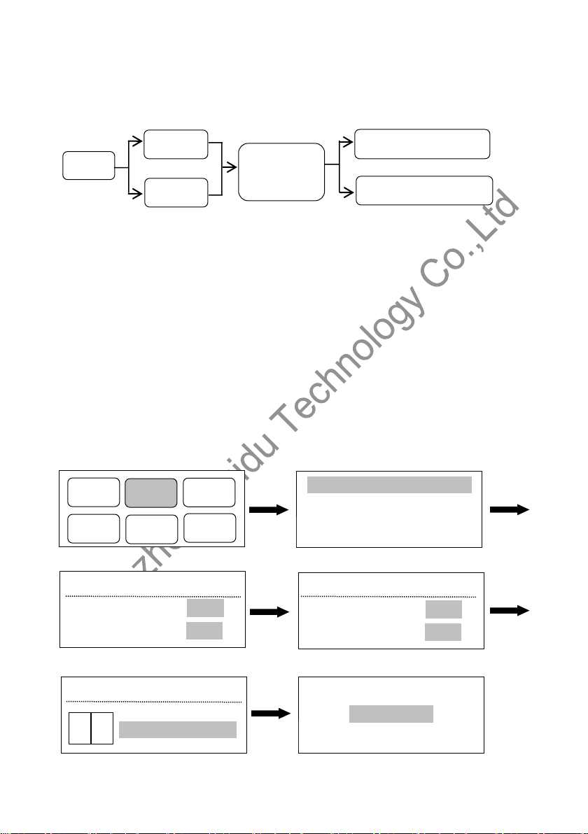
-----Splice Wizard----
1、 set the channel A, B resolution
Output A channel:Default menu→Output→Output A→Custom resolution→Horizontal width(Knob
adjustment size)→Vertical height(Knob adjust size)→Change resolution
Output B channel:Default menu→Output→Output A→Custom resolution→Horizontal width(Knob
adjustment size)→Vertical height(Knob adjust size)→Change resolution
2、Set up splicing
Default menu →splice→ splice setup wizard→Set A screen size(Horizontal width、Vertical height,
OK key selection determination)→Set B screen size(Horizontal width、Vertical height,OK key
selection determination) →Set splicing mode(Horizontal / vertical splicing, OK key selection
determination)
Schematic diagram is as follows:(such as one screen is 1408 x896,Another screen is 1280x896,
The resolution of the entire large screen is 2688 x 896)

5
introduction
This manual contains information about how to use, install and configure the LED video processor, in
addition, also relates to knowledge LED video processor and LED video systems. Users are LED
video processor, please read this manual in detail.
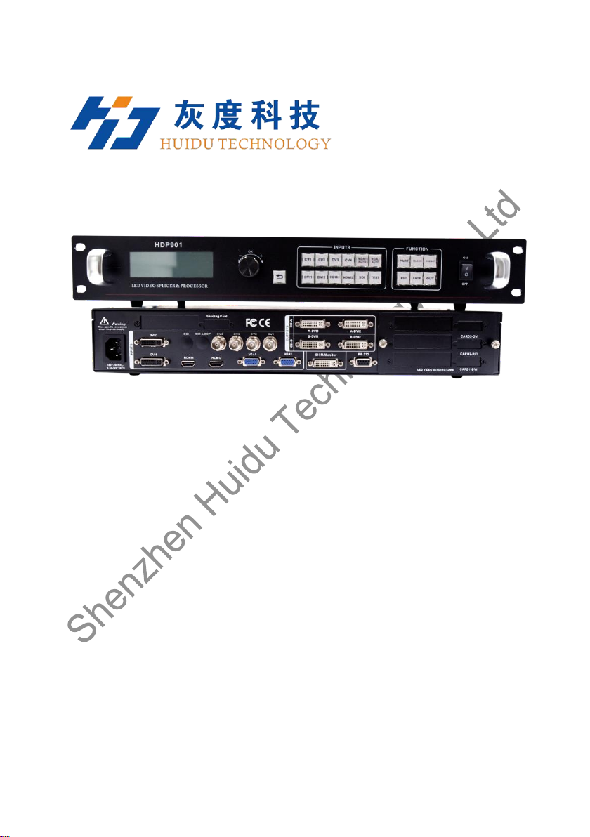
About LED Video Processor
The LED splicing processor has three powerful video processing core, multi input multi graphics
intelligent splicing processor, can be widely used in performing arts activities, command and control
center, video conference, hotel, meeting room and court.
LED splicing processor can accommodate a wide range of input sources,Two channels for splicing,
A channel for monitoring. 2 * 1 or 1 * 2 channel hybrid splicing、Single maximum splicing can achieve
5 million 300 thousand pixel custom output.More simple splicing settings,1 minutes can be set to
complete
LED splicing processor can accommodate a wide range of input sources.Can access up to eleven
channels of video input,Contains two DVI,Contains two HDMI,Contains four VIDEO,One
3G-SDI(Optional)。Each channel can receive standard resolution or high resolution video signal.DVI,
and VGA can receive up to 1920 x 1200@60Hz of resolution input,Meet all kinds of HD output.
splicing processor design more humane,It is easier to use under the powerful function,Simple use of
the button panel and menu system,As long as the touch of your finger to complete the complex
set.Use the front panel and RS-232 can achieve the complete set and operation.Provides rich
physical interface,Can meet the needs of common output devices.Provides up to 4 LED send card
installation location,Simplify the installation of a large number of settings.Rotate quickly adjust the
screen or related parameters,User settings handy.
6
Panel
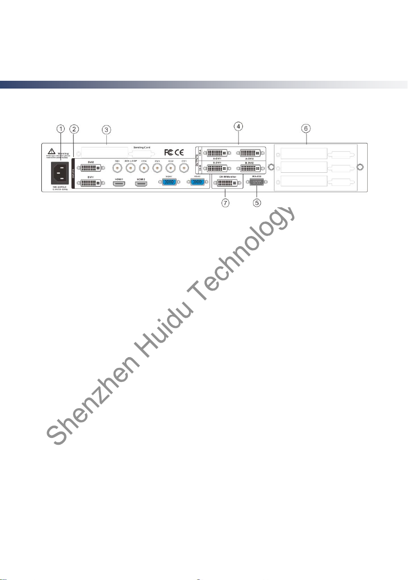
Rear Panel
Figure 1-Video processor rear panel
① AC power input - using IEC standard power cable video processor, the input power is 100-240
VAC, 50-60Hz.
② ideo input — Input criteria for each interface。
● CV1, CV2, CV3 , CV4 CVBS video input, BNC connector, input video support PAL, PAL-M / N,
NTSC, SECAM formats. You can connect DVD players and camcorders.
● DVI1, DVI2 input, DVI-I standard interface, use the DVI-I or DVI-D cable, the video input format
supports VESA standard.
● HDMI HD video input, HDMI-A standard interface, support HDMI1.3 standard video inputs and
VESA standards. Used to connect desktop computers and HDMI high-definition player.
● VGA1, VGA2 video input, using the standard DB-25 connector, supports the VESA standard video
input for connecting a desktop computer, laptop or other VGA video output device.
● SDI digital video input,SDI-LOOP,SDI Signal ring out,Using BNC interface,Enter the video
support HD video camera, etc..
④ video output - video output interface processor programming
● DVI output, using the DVI-I connector, the output video format is set by the processor, two DVI
outputs the same signal at the same time. Used to send the card or connected to the LED monitor.
⑦ CH-M/Monitor output,using the DVI-I connector,Output video to display,As a display of the user's
real-time operating image location and switching effects.
⑤ RS-232 - Serial communication connector for engineering testing, the device is programmed, PC
software control, communication baud rate is 115200bps.
③⑥ LED sending card - LED sending card installation location aside, you can install one or two to
send cards. When installed, the user can first open the back cover and the small bracket, mounting,
internal set aside four 5V power connector, four 2.0x4PIN connectors. After installing the plug 5V
power supply.
 Loading...