

www.hugo-mueller.de BA HUpro GB -22989- 2014-07-V03 - ED - A3 Seite 1
GB
Additional instruction master clock Site 1 / 2
PLEASE NOTE!!!
SAFETY INSTRUCT IONS
(SC 58.17 pro / SC 98.47 pro / S C 53.17 pro / SC 93.47 pro)
Please note the following for masterclock with time switch functionality:
This manual de scribes only masterclock features. Time switch relevant description can be
found in the standard time switch manual!
Only the connection diagram, initial operations and the safety instructions of this manual is
valid.
!!ATTENTION!! DANGER OF LIFE / RISK OF FIRE AND ELECTRIC SHOCK!!!
=> Installation and assembly of electrical equipment must be carried out only by a skilled person!!!
=> Disconnect device from power supply for wiring and installation purposes!!!
=> Defective devices have to be put out of service immediately!!!
Connect the supply voltage/frequency as stated on the product!
Warranty void if housing opened by unauthorised person!
The electronic circuit is protected against a wide range of external influences. Incorrect operating may occur if
external influences exceed certain limits!
Installation and assembly of electrical equipment must be in accordance with local building and electrical
codes!
The disposal of the device (and batteries) must be in accordance with the valid environmental and national law!
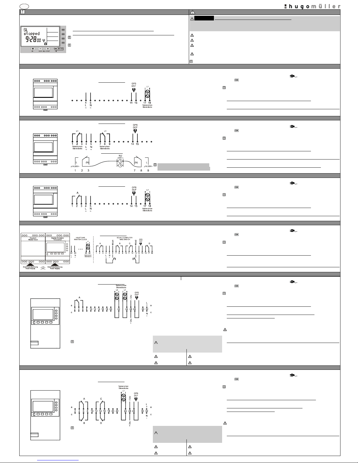
SC 58.07 pro ( DIN rail mounting – master clock)
Technical data slave-clock-line (SL)
Initial operation
SC 58.07 pro
Connection diagram
Number of lines: 1
Output voltage: 24VDC
Output current: 35mA
Conn. terminals: 17 / 18
Max. number clocks: approx. 5 slave clocks
Output signal: Pole changing pulse
Pulse sequence: Normal opera tion = 1/min
During adjustment = 10/min
Pulse length: 2 se c.
(Pulse sequence/length adjustable)
The time switch is delivered in power back up mode (battery mode).
The display shows the power plug symbol [flashing ].
Press -button for 1 second. The display switches to automatic-mode.
(Displaying the time and the current status of the slave-clock- line (SL)).
The master clock is already programmed with the current date and time and European
daylight savings time is activated. The slave-clock- line is preset as follows: Minute-line
activated / start time 12:00 / Slave-clo ck-line (SL) is stopped.
Power supply master clock ( See connection diagram on the left)
Connect the supply voltage/frequency as stated on the product!
Connection slave-clock- line (SL) => master clock (See
connection diagram on the left)
Connect slave-clock- line to terminal no. 17 and 18 of the master clock.
SC 58.08 pro ( DIN rail mounting – master clock)
Technical data slave-clock-line (SL)
Initial operation
SC 58.08 pro
Connection diagram
Connection sample
Number of lines: 1
Output voltage: Max. 250V~ (potential -free)
Output current: 1A
Conn. terminals: 2 / 8
Max. number clocks: Depends on the slave clocks
Pulse sequence: Norm al operation = 1/min
During adjustment = ca. 6/min
Pulse length: 8 sec.
(Pulse sequence/length adjustable)
PLEASE NOTE: The two relays are
energized alternately every minute.
The time switch is delivered in power back up mode (battery mode).
The display shows the power plug symbol [flashing ].
Press -button for 1 second. The display switches to automatic-mode
(Displaying the time and the current status of the slave-clock- line (SL)).
The master clock is already programmed with the current date and time and European
daylight savings time is activated. The slave- clock-line is preset as follows: Minute-line
activated / start time 12:00 / Slave-cl ock-line (SL) is stopped.
Power supply master clock (See connection diagram on the left)
Connect the supply voltage/frequency as stated on the product!
Connection slave-clock- line (SL) => master clock (See
connection diagram on the left)
Connect slave-clock- line to terminal no. 2 and 8 of the master clock.
Power supply slave-clock-line (S L) (See connection diagram on the left)
Connect power suppl y for clock motor(s) to terminals 1 / 9 and 3 / 7
SC 58.17 pro ( DIN rail mounting – master clock with t ime switch functianali ty / weekly time switch)
Technical data slave-clock-line (SL)
Initial operation
SC 58.17 pro
Connection diagram
Number of lines: 1
Output voltage: 24VDC
Output current: 150mA
Conn. terminals: 17 / 18
Max. number clocks: approx. 20 slave clocks
Output signal: Pole changing pulse
Pulse sequence: Normal opera tion = 1/min
During adjustment = 10/min
Pulse length: 2 sec.
(Pulse sequence/length adjustable)
The time switch is delivered in power back up mode (battery mode).
The display shows the power plug symbol [flashing ].
Press -button for 1 second. The display switches to automatic-mode
(Displaying the time and the current status of the slave-clock- line (SL)).
The master clock is already programmed with the current date and time and European
daylight savings time is activated. The slave- clock-line is preset as follows: Minute-line
activated / start time 12:00 / Slave-cl ock-line (SL) is stopped.
Power supply master clock (See connection diagram on the left)
Connect the supply voltage/frequency as stated on the product!
Connection slave-clock- line (SL) => master clock (S ee
connection diagram on the left)
Connect slave-clock- line to terminal no. 17 and 18 of the master clock.
SC 98.47 pro ( DIN rail mounting – master clock with t ime switch functianalit y / yearly time switch)
Technical data slave-clock-line (SL)
Initial operation
SC 98.47 pro
Connection diagram
Number of lines: 1
Output voltage: 24VDC
Output current: 300mA
Conn. terminals: 35 / 36
Max. number clocks: approx. 40 slave clocks
Output signal: Pole changing pulse
Pulse s equence: Normal operation = 1/min
During adjustment = 10/min
Pulse length: 2 sec.
(Pulse sequence/length adjustable)
The time switch is delivered in power back up mode (battery mode).
The display shows the power plug symbol [flashing ].
Press -button for 1 second. The display switches to automatic-mode
(Displaying the time and the current status of the slave-clock- line (SL)).
The master clock is already programmed with the current date and time and European
daylight savings time is activated. The slave- clock-line is preset as follows: Minute-line
activated / start time 12:00 / Slave-cl ock-line (SL) is stopped.
Power supply master clock (See connection diagram on the left)
Connect the supply voltage/frequency as stated on the product!
(Master clock = terminals 22/23 / Time switch = terminals 4/5).
Connection slave-clock- line (SL) => master clock (S ee
connection diagram on the left)
Connect the sla ve-clock-line (SL) to the master clock on termina ls 35 and 36
SC 53.17 pro ( 19”-housing – master clock with time sw itch functianality / weekly time swit ch)
Technical data slave-clock-line (SL)
Initial operation
SC 53.17 pro
Connection diagram
SC 53.17: 2 NU-Linie
The signal output for line 1 and line 2 can be configured
independently to emit pulses either every second or every minute!
NOTE! Power supply from a third party supplier:
The usage of a switched-mode power supply to drive the slave clock line
might disturb the reception of the FU 20.00 pro radio receiver. If the radio
receiver has no reception (the green LED on the bottom of the radio
receiver flashes rapidly or not at all) please connect GND of your
switched-mode power supply via an Y-capacitor with protective earth.
Number of lines: 2
Input USL: 24V DC (12VDC/48VDC/60V DC)
(Monitoring USL - switch able)
Output current: up to 1500mA for each l ine
(Depends on the power supply)
Conn. terminals: See conn. diagram on the left
Max. number clocks: approx. 200 slave clocks
(each line)
Output signal: Pole changing pulse
Pulse sequence: Normal opera tion = 1/min
During adjustment = 10/min
Pulse length: 2 sec.
(Pulse sequence/length adjustable)
Module: NT 73 (Power adapter slave line)
Not included in delivery!
The time switch is delivered in power back up mode (battery mode).
The display shows the power plug symbol [flashing ].
Press -button for 1 second. The display switches to automatic-mode
(Displaying the time and the current status of the slave-clock- line (SL)).
The master clock is already programmed with the current date and time and European
daylight savings time is activated. The slave- clock-line is preset as follows: Minute-line
activated / start time 12:00 / Slave-clock-line (SL) is stopped.
Power supply master clock (See connection diagram on the left)
Connect the supply voltage/frequency as stated on the product! (Terminals 32a und 32c).
Connection power supply the slave-clock-line (SL) => master clock
(See connection diagram on the left)
Depending on the specifications of the slave clocks, connect 12VDC; 24VDC; 48VDC; or
60VDC to terminals 26a and 26c.
Check polarity.
For voltages of slave clocks which differ from 24VDC, the dip switches on the PCB have to
be configured as stated within the table on the left.
Connection slave-clock- line (SL) => master clock (S ee
connection diagram on the left)
Connect slave-clock- line to:
Line 1 [L1] => terminals 24a und 24c
Line 2 [L2] => terminal s 22a und 22c
Table dip switches
(Power supply monitoring of the slave-clockline)
SL S1 S2
SL S1 S2
12VDC ON ON 48VDC OFF ON
24VDC ON OFF 60VDC OFF OFF
SC 93.47 pro ( 19”-housing – master clock with tim e switch functian ality / yearly time switch)
Technical data slave-clock-line (SL)
Initial operation
SC 93.47 pro
Connection diagram
NOTE! Power supply from a third party supplier:
The usage of a switched-mode power supply to drive the slave clock line
might disturb the reception of the FU 20.00 pro radio receiver. If the radio
receiver has no reception (the green LED on the bottom of the radio
receiver flashes rapidly or not at all) please connect GND of your
switched-mode power supply via an Y-capacitor with protective earth.
Number of lines: 1
Input USL: 24V DC (12VDC/48VDC/60V DC)
(Monitoring USL - switchable)
Output current: up to 1500mA
(Depends on the power supply)
Conn. terminals: See conn. diagram on the left
Max. number clocks: approx. 200 slave clocks
Output signal: Pole changing pulse
Pulse sequence: Normal operation = 1/min
During adjustment = 10/min
Pulse length: 2 sec.
(Pulse sequence/length adjustable)
Module: NT 73 (Power adap ter slave line)
Not included in delivery!
The time switch is delivered in power back up mode (battery mode).
The display shows the power plug symbol [flashing ].
Press -button for 1 second. The display switches to automatic-mode
(Displaying the time and the current status of the slave-clock- line (SL)).
The master clock is already programmed with the current date and time and European
daylight savings time is activated. The slave- clock-line is preset as follows: Minute-line
activated / start time 12:00 / Slave-cl ock-line (SL) is stopped.
Power supply the master clock (See connection diagram on the left)
Connect the supply voltage/frequency as stated on the product! (Terminals 32a und 32c)
Connection power supply slave clockline => master clock
(See connection diagram on the left)
Depending on the specifications of the slave clocks, connect 12VDC; 24VDC; 48VDC; or
60VDC to terminals 26a and 26c.
Check polarity.
For voltages of slave clocks w
hich differ from 24VDC, the dip switches on the PCB have to
be configured as stated within the table on the left.
Connection slave-clock- line (SL) => master clock (S ee
connection diagram on the left)
Connect slave-clock- line to terminal no. 24a and 24c of the master clock.
Table dip switches
(Power supply monitoring of the slave-clockline)
SL S1 S2
SC S1 S2
12VDC ON ON 48VDC OFF ON
24VDC ON OFF 60VDC OFF OFF
www.hugo-mueller.de BA HUpro GB -22989- 2014-07-V03 - ED - A3 Seite 2
GB
Additional instruction master clock Site 2 / 2
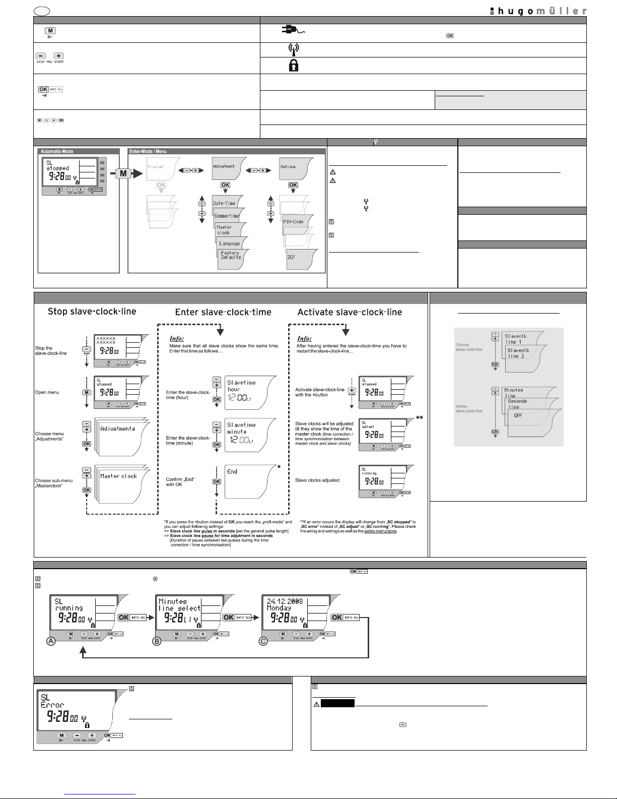
Button function
Symbol legend
1. Automatic-Mode: To access the enter-mode
2. Enter-Mode: To revert to the beginning of the curr ent (sub-)menu.
Power plug symbol (flashing): While the power supply is disconnected, the display shows a power plug symbol. The
time switch is then operated in the battery mode. Press
-button for 1 sec. to “wake up” the time switch.
1. Automatic-Mode: STOP = Deactivation slave-clock-line (SL)
2. Automatic-Mode: START = Activation slave- clock-line (SL)
3. Enter-Mode: To adjust the flashing digit. To scroll through a choice
DCF/GPS: The master clock receives the signal for the DCF77 time standard.
PIN: The time switch is locked; to unlock the device the PIN has to be entered.
1. To activate the time switch when operated without power supply.
2. Automatic-Mode: INFO NU (INFO S L) => Press OK [Info NU] to change the displayed
information while the device is in the Automatic-Mode.
3. Enter-Mode: To confirm the selection or the entered data.
SL stopped
The slave clocks receive no pulses from the master clock . The sla ve clocks are stopped . The missing pulses are stored.
After reactivation these pulses will be caught up.
SL running
Slave clocks are pulsed / clocked every minute
Exception SC53.17pro:
If you have selec ted minutes-line: Slave clocks are pulsed every minute
If you have selected seconds-line : Slave clocks are pulsed ever y second
RESET: Press all front keys for 2 seconds. The time switch is reset. The values for date
and time will be deleted and have to be re-entered. The switching program has not been
deleted!
SL adju st
Slave clocks will be adjusted till they show the time of the master clock (time correction / time synchronisation)
SL err or
There is a power failure, overload or short circuit of the slave-clock- line (SL).
No pulses are sent to the slave- clock-line (SL).
Menu overview (Automatic-Mode / Enter-Mode)
DCF / GPS rec eiver
Summertime / W intertime
*Menu only available for master clocks with time switch functionality. For details please see the manual of the time switch:
SC 58.17 pro (DIN rail mounting) / SC 98.47 pro ( DIN rail mounting) / SC 53.17 pr o (19”-housing) / SC 93.47 pro (19”- housing)
The device can process a DCF77-type telegram. The
antenna (receiver) is not included in delivery.
Initial operation of the antenna for DCF/GPS time
NOTE SAFETY INSTRUCTION!!
DISCONNECT POWER SUPPLY!!
Connect antenna as stated (manual of antenna)
Connect power suppl y
DCF-Symbol flashes (approx. 3 minutes)
DCF-Symbol appears static and synchronization
succeeded
Permanent blin king of DCF-Symbol = permitted s ignal no
reception possible (time base is the internal quar tz)
No DCF-Symbol = antenna not connected
(time base is the internal quartz)
Adjustment of the atomic clock b ase:
Within menu
Options
->
DCF
an offset to GMT is already
configured and can be adjusted! Standard: GMT+1 => CET
The daylight saving time will be adjusted automatically
according to the selected settings (
Adjustments
->
Summertime:
(standard European rule))
Details daylights saving tim e slave clocks
With 60 additional pulses of 1 h. pulse suppression of the
slave-clock- line (SL).
Factory Default s
Within the menu Adjustments - > Factory defaults you
can reset the master clock to the state of delivery. Date,
time and switching pr ogram will be lost!
PIN-Code
Within the menu Options -> PIN-Code the device can be
locked with a 4-digit PIN-
Code. The code can be adjusted,
activated and deactivated. If you have forgotten the code
please call customer service.
Set and define slave-clock-line (SL) / Activate slave-clock-line (SL)
Exception SC 53. 17 pro
The SC 53.17 pro has two slave-clo ck-lines!!!
Before entering the standard settings of the master clock
(see on the left)
you have to confirm or adjust following line configurations:
INFO function
During regular operation (Automatic-Mode) different informations and adjustments of master clock and slave-clock-line can be displayed by pressing .
After 1 minute the clock changes to standard display automatically!!!
If
SL error
is shown an info query is not possible. Please carry out corrective actions first!!!
NU = SL [slave-clock-line]
Error / Recovery system of the slave-clock-line (SL)
Failure: Sla ve clocks are 1 minute to late / Slave clocks are 1 minute to early
If there is a power failure, overload, short-
circuit or incorrect wiring of the
slave-clock- line as well as a power failure of the slave-clock-powersupply “
SL error””
is displayed!!
Recovery system:
If “
SL error””
is displayed no pulses are sent via slave-clock-line. The
complete quantity of suppressed pulses are saved and emitted
(SL adjust
)
after corrective actions or power resumption (
SL running
).
If a slave clock is poled reversely the slave clocks are 1 minute late or early!!!
Corrective action:
!!ATTENTION!! DANGER OF LIFE / RISK OF FIRE AND ELECTRIC SHOCK!!!
=> Installation and assembly of electrical equipment must be carried out only by a skilled person!!!
=> Disconnect device from power supply for wiring and installation purposes!!!
Stop sla ve-clock-line (SL)!! Press the -button [STOP] . „
SL stopped
“ is displ ayed.
Switch the corresponding wiring !!!PLEASE NOTE THE SAFETY INSTRUCTIONS!!!
Enter slave-clock-time
Activate slave-clock -line
 Loading...