

Page 1

1.0
BEDIENUNGSANLEITUNG
MANUAL
ENGLISH
Page 2

PROJECTOR MANUAL
Table of Contents
1. PROJECTOR System Components . . . . . .6
1.1 PROJECTOR MID-HIGH UNIT . . . . . . . . . . . . . .6
1.2 PROJECTOR SUB 1 and SUB 2 . . . . . . . . . . . . .7
2. Setting up the System . . . . . . . . . . . . . .8
2.1 Standard System . . . . . . . . . . . . . . . . . . . . . .8
2.2 Standard System with Tilt Unit . . . . . . . . . . . .8
2.3 How to Fly the MID-HIGH UNIT . . . . . . . . . . .9
2.4 Double PROJECTOR System . . . . . . . . . . . . . .9
3. Connections . . . . . . . . . . . . . . . . . . . . .10
4. Powering Up . . . . . . . . . . . . . . . . . . . .10
5. Settings . . . . . . . . . . . . . . . . . . . . . . . .10
6. Helpful Hints . . . . . . . . . . . . . . . . . . . .11
WELCOME TO THE
HK AUDIO FAMILY!
Congratulations on choosing PROJECTOR, a three-way active
sound reinforcement system with the power of a large PA and
the advantages of state-of-art active electronics. Not only is it
easy to transport, you’ll also find that it takes no time at all to
set up and connect PROJECTOR. These advantages and its
remarkable ease of use make PROJECTOR a professional
sound reinforcement system well-suited for larger events.
PROJECTOR is comprised of three different cabinets that come
complete with all the required electronic components on board.
As its name would indicate, the MID-HIGH UNIT reproduces
the middle and upper range frequencies via a 12" speaker and
a 2" driver, each powered by a 300-watt power block. SUB 1
and SUB 2 are two different subwoofers equipped with an
18" speaker and a 600-watt power amp each. For maximum
performance and reliability, all cabinets feature a built-in
controller with a limiter and crossover.
A complete PROJECTOR PA system consists of
a MID-HIGH UNIT,a SUB 1 and a SUB 2 on each side.
ENGLISH
7. Technical Specifications . . . . . . . . . . . .11
8. Safety Instructions for Flying the System .12
With all the circuitry integrated into the housings, this system
benefits from shorter signal paths, electronic circuitry that is
fine-tuned specifically to match the built-in speakers, and
active frequency compensation. Taken together, this results in
excellent dynamic and pulse response, maximum protection
against overload, and superior sound. Those tedious soundchecking and fine-tuning chores fall by the wayside, and you’ll
only need to fall back on an equalizer if you have to
compensate for a given venue’s acoustic peculiarities.
5
Page 3
PROJECTOR MANUAL
LONG THROW
MID THROW
PROJECTORPROJECTOR
1. PROJECTOR SYSTEM COMPONENTS
1.1 MID-HIGH UNIT
-6 dB
SIGNAL/
117 V~ 6.0 A
SOFT LIMIT/
FULL LIMIT
0 dB
ON LIFT
GAINLONG THROW
HF MF
GROUND
SELF-POWERED
LONG THROW SYSTEM
PROJECTOR
600 W RMS MID-HIGH UNIT
MAINS
INPUT
POWER
ON
CAUTION!
SUB
TO PREVENT THE RISK OF FIRE
OFF
50 - 60 HZ
BEFORE RESETTING
CIRCUIT BREAKER!
Ser.No.
REFER SERVICING TO QUALIFIED
MID-HIGH
AND SHOCK HAZARD DON´T
EXPOSE THIS APPLIANCE TO
CIRCUIT
MOISTURE OR RAIN. DO NOT
BREAKER
SERVICEABLE PARTS INSIDE.
TURN OFF SYSTEM
OPEN CASE; NO USER
SERVICE PERSONNEL.
2
SUB
1
MID THROW
INPUT THROUGH
®
MADE IN GERMANY
NRTL (Fairfield)
NRTL (Fairfield)
UL 6500
UL 6500
MAX. POWER CONSUMPTION 950 VA
CAUTION!
TO PREVENT THE RISK OF FIRE AND SHOCK HAZARD
DON´T EXPOSE THIS APPLIANCE TO MOISTURE OR
RAIN. DO NOT OPEN CASE.
NO USER SERVICEABLE PARTS INSIDE.
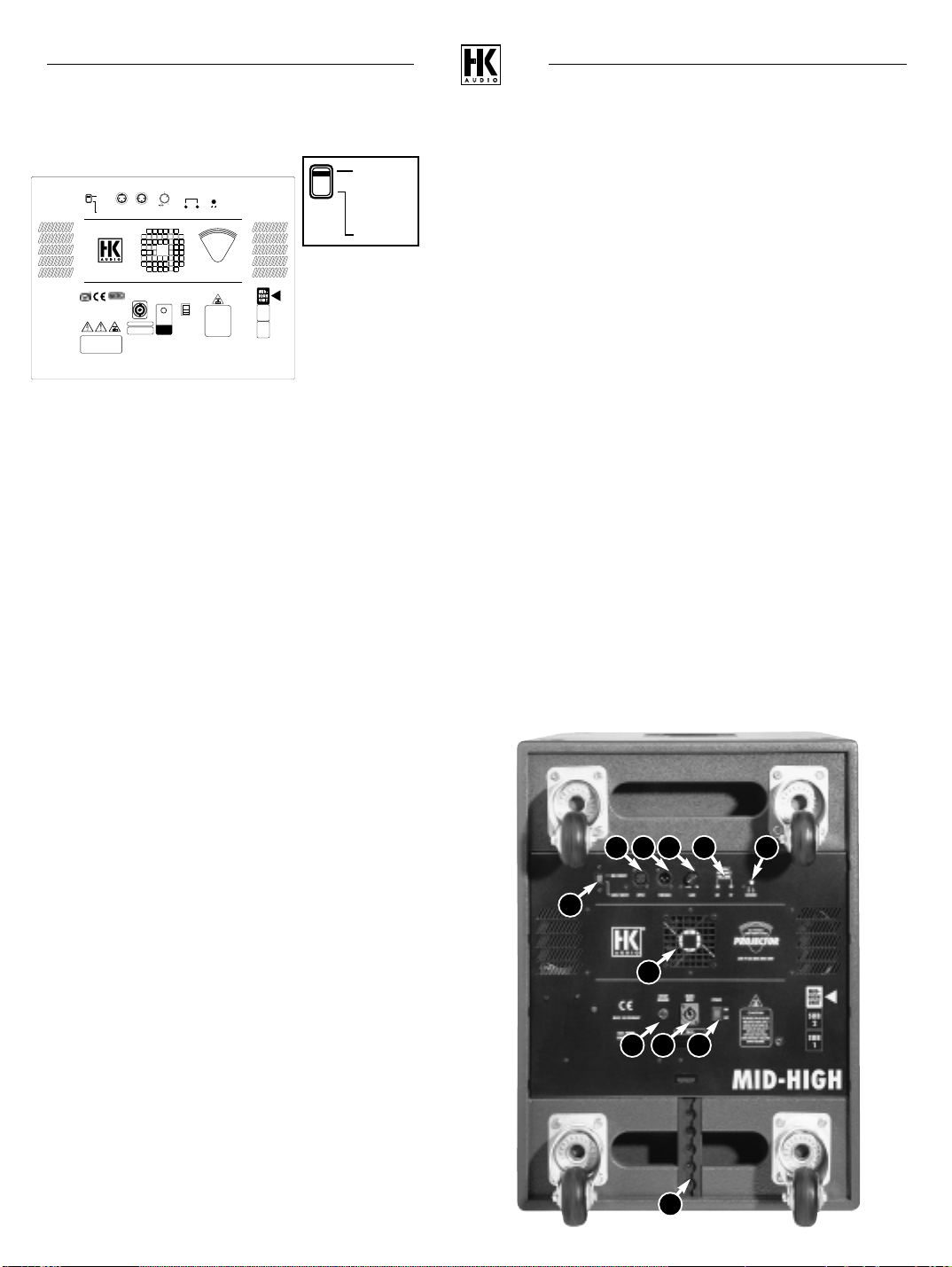
The top unit of the active PROJECTOR system houses a 12” B&C woofer
and a B&C 2" high-frequency driver, both loaded onto 60° x 40°
concentric horns, as well as all the necessary active electronic components
to control and drive them. The Mid Throw / Long Throw switch lets you
choose one of two frequency compensation options for either short and
middle distances or long distances. For distances up to 20 meters, set the
switch to Mid Throw; for distances greater than 20 meters, set it to
Long Throw.
The enclosure is equipped with casters and Aeroquip flight rails as
standard features. These rails, which are mounted on both sides and in a
recessed groove on the rear panel, make it easy to fly the cab.
6. MID THROW / LONG THROW SWITCH
Selects appropriate frequency compensation depending on distance. In
LONG THROW mode, the system’s EQ boosts high frequencies by about
three decibels so that the top end is not lost when the signal is projected
over greater distances. For distances up to 20 meters, set the switch to
MID THROW, for greater distances to LONG THROW.
7. VENTILATION UNIT
This ventilating fan keeps the power amp modules cool. Always make sure
that the fan and the vents are kept free of dirt and debris and that they
remain unobstructed so air can circulate freely.
8. CIRCUIT BREAKER
This automatic circuit breaker serves the same purpose as the standard
fuses that you may be familiar with. If it trips, once you have identified
the problem you can reset the circuit breaker by simply pressing it.
Caution: Always switch the system off before you reset the circuit breaker
(take a look at the mains power switch and make sure it is set to OFF)!
9. MAINS INPUT
This Neutrik Powercon socket accepts the mains cable. This is a relatively
new type of connector system featuring a locking mechanism which
prevents the mains cord from being pulled out inadvertently.
10. "POWER" SWITCH
On/off switch for the electronics in the speaker cabinet. It lights up red
when the cab is powered up.
Rear Panel:
1. INPUT
Electronically balanced input designed to accept the balanced output
signal coming from the mixer (1= ground, 2= +, 3= -)
2. THROUGH
This is a parallel output you can use for routing the LINE signal to
additional equipment, such as other systems, individual components,
monitor power amps, etc.
3. GAIN
This knob lets you adjust the power amp to match the input signal level;
reduce it to prevent distortion when you’re patching in signals that are
already fairly hot.
4. MF AND HF LIMITER LED
Indicates the operating status of the limiter. Green = signal present,
yellow = soft limit, red = full limit. NOTE: This is not a clipping indicator;
it is acceptable for it to light up every now and then in red. This tells you
that the limiter is operating at full capacity. The limiter status of the
middle (MF) and high (HF) frequency ranges is indicated in each case by a
dedicated LED.
5. GROUND
Ground lift switch for separating the signal and chassis ground when you
encounter problems with hum due to ground loops resulting from
duplicate paths to ground. The connection from signal ground to chassis
is interrupted when you press the button in.
6
11. AEROQUIP FLIGHT RAILS
These rails are designed to accept steel cables equipped with Aeroquip
studs (see the chapter on Setup / Stacking) to fly the cabinets safely
and securely.
1 2 3 4 5
6
7
8 9 10
11
Page 4

PROJECTOR MANUAL
®
SUB 1
SUB
2
SUB
1
CAUTION!
TO PREVENT THE RISK OF FIRE
AND SHOCK HAZARD DON´T
EXPOSE THIS APPLIANCE TO
MOISTURE OR RAIN. DO NOT
OPEN CASE; NO USER
SERVICEABLE PARTS INSIDE.
REFER SERVICING TO QUALIFIED
SERVICE PERSONNEL.
INPUT THROUGH
POWER
GAIN
ON
OFF
600 W RMS SUBWOOFER
SIGNAL/
SOFT LIMIT/
FULL LIMIT
SELF-POWERED
LONG THROW SYSTEM
PROJECTORPROJECTORPROJECTOR
-6 dB
0 dB
ON LIFT
GROUND
Ser.No.
MAINS
INPUT
50 - 60 HZ
MAX. POWER CONSUMPTION 950 VA
117 V~ 6.0 A
NRTL (Fairfield)
UL 6500
NRTL (Fairfield)
UL 6500
CAUTION!
TO PREVENT THE RISK OF FIRE AND SHOCK HAZARD
DON´T EXPOSE THIS APPLIANCE TO MOISTURE OR
RAIN. DO NOT OPEN CASE.
NO USER SERVICEABLE PARTS INSIDE.
MADE IN GERMANY
CIRCUIT
BREAKER
TURN OFF SYSTEM
BEFORE RESETTING
CIRCUIT BREAKER!
1.2 SUB 1 and SUB 2
The PROJECTOR SUB 1 and SUB 2 subwoofers
are each equipped with a horn-loaded 18" B&C speaker. The horn and
pressure chamber of these cabinets are designed so that sound pressure
waves actively cool the massive magnet and voice coil of the 600-watt
speaker; the harder it works, the stronger the cooling effect.
The interiors of the two subwoofers are identical, though the SUB 2’s
layout is actually a mirror image of the SUB 1’s. There is a simple yet very
compelling reason for this design. When you stack the subwoofers (see the
diagram "Stacking subwoofers") as intended, the two halves actually form
a full horn so that the configuration delivers more bottom-end sound
pressure over a greater distance.
6. VENTILATION UNIT
This ventilating fan keeps the power amp modules cool. Always make sure
that the fan and the ventilation vents are kept free of dirt and debris and
that they remain unobstructed so air can circulate freely.
7. CIRCUIT BREAKER
This automatic circuit breaker serves the same purpose as the standard
fuses that you may be familiar with. If it trips, once you have identified
the problem you can reset the circuit breaker by simply pressing it.
Caution: Always switch the system off before you reset the circuit breaker
(take a look at the mains power switch and make sure it is set to OFF)!
8. MAINS INPUT
Neutrik Powercon socket designed to take the mains cord. A new type of
connector system featuring a locking mechanism, it prevents the mains
cord from being pulled out inadvertently.
9. "POWER" SWITCH
On/off switch for the speaker cabinet. Lights up red when the cab is
powered up.
Rear Panel:
1. INPUT
Electronically balanced input designed to accept the balanced output
signal from the mixing console by way of the THROUGH output of the
Projector Mid/High Unit (1= ground, 2= +, 3= -)
2. THROUGH
This is a parallel output you can use for routing the LINE signal to
additional equipment, such as other systems, individual components,
monitor power amps, etc
3. GAIN
This knob lets you adjust the power amp to match the input signal level;
reduce it to prevent distortion when you’re patching in signals that are
already fairly hot.
4. LF LIMITER LED
Indicates the operating status of the limiter. Green = signal present,
yellow = soft limit, red = full limit. NOTE: This is not a clipping indicator;
it is acceptable for it to light up every now and then in red. This tells you
that the limiter is operating at full capacity.
5. GROUND
Ground lift switch for separating the signal and chassis ground from each
other when you encounter problems with hum due to ground loops
resulting from duplicate paths to ground. The connection from signal
ground to chassis is interrupted when you press this button in.
1 2 3 4 5
ENGLISH
6
7 8 9
7
Page 5

PROJECTOR MANUAL
Stage
35 m
6 m
8 m
6 m
Stage
35 m
6 m
5 m
tilt 0°
tilt 5°
10 m
reflection
reflection
23 m
30 m
Stage
35 m
6 m
4 m
tilt 10°
14 m
reflection
30 m
15 m
Stage
35 m
6 m
3 m
tilt 15°
23 m
reflection
30 m
10 m
2. SETTING UP THE SYSTEM
2.1 Standard System
Setup/Stacking: SUB 1 – SUB 2 – MID-HIGH UNIT!
Here’s how you set up the standard system configuration: Always set up
the cabinets as illustrated in the diagram. Set SUB 1 on the floor, SUB 2
on SUB 1, and the MID-HIGH UNIT on top of the stack.
In this configuration, the subwoofers form a full horn and provide the
greatest possible output.
2.2 Standard System with Tilt Unit
PROJECTOR Tilt Unit
(Cabinets with serial number 317961 and higher are factory-equipped
with mounting units. For all PROJECTOR cabinets with lower serial
numbers HK Audio provides a retrofit kit with instructions and all
required parts.)
The Tilt Unit (see the diagram) is a practical tool designed to assist in
aiming stacked PROJECTOR MID-HIGH UNITS directly at the area that
you want the system to cover. This ensures that the sonic energy projected
by the system can be used more effectively. The Tilt Unit offers three
angles of tilt: 5°, 10° and 15°. These options let you adjust the
MID-HIGH UNITS to match the venue and the given position of the
PROJECTOR system. For example, if the system is set on a relatively high
platform (one meter or higher), you should select tilt angles of 10° or 15°
for shorter distances, and 5° for longer distances (e.g. in a big tent or
long hall). If the system is set on a low platform, for example at a height
of 0.2 to 0.6 meters (1 - 2 ft.), you should tilt the mid-high units at an
angle no greater than 5° to 10°.
If at all possible, be sure to place the system on a raised platform or stage
so that the mid-high unit is situated above the heads of the audience.
We recommend a platform with a height of about 2 to 3 feet, or 0.5 to
1 meters, depending on the size of the venue and how far you want the
system to project. The rule of thumb is, the longer the venue or greater
the distance you want to cover, the higher you should position the MID-
HIGH UNITS. To aid in positioning, we offer the PROJECTOR Tilt Unit as
an option, which lets you adjust the angle of the MID-HIGH UNIT with
greater precision so that it faces the audience directly (more on this in the
following section).
8
Page 6

PROJECTOR MANUAL
A
A
A
25°
To mount the Tilt Unit, proceed as follows:
1. Set the PROJECTOR system up as described above
2. Remove the recessed socket head screws (A) from the SUB 2’s side
panels (two screws per side) as well as from the MID-HIGH UNIT’s
panels (1 screw per side)
3. Attach the Tilt Unit’s steel brackets (B) to the SUB 2’s housing using
two star grip screws (C) each. Make sure that the screws are fastened
tightly and that they hold the steel brackets firmly in place.
4. Insert the star grip screws with bearings (D) through the Tilt Unit’s steel
brackets into the threads on the mid-high unit and fasten them tightly.
5. Now tilt the back of the mid-high unit upwards by applying pressure
to the back of the housing. Allow the Tilt Unit to engage at the
desired angle.
2.3 Flying the Mid-High Units
The PROJECTOR MID-HIGH UNITS are equipped with three eightposition Aeroquip flight rails that allow the cabinets to be flown
(i.e. allow the cabs to be hung from a cross beam or flight rig). These rails
are designed to be used with steel cables that are available as an optional
accessory. The rails on the left and right side of the housing serve to
actually “fly,” i.e. suspend the cabinet. The rear rail, in turn, is designed to
accept an additional steel cable that lets you adjust the tilt angle of the
MID/HIGH UNITs. The proper angle for the Mid/High units depends on
the height at which they are suspended and of course the type of venue.
The tilt angle can be varied slightly by means of the eight-position angles
on the rails as well as by the tension exerted by a cable attached to the
rail on the rear panel.
CAUTION! Always make absolutely sure that the points at which you attach the
Mid-High units (e.g. aluminum cross beam or a rigging point in the ceiling of the
venue) have sufficient load-carrying capacity and satisfy the applicable safety
standards. If you are in doubt, be sure to seek the advice of a structural engineer,
rigger or the venue’s technician.
(See notes on flying safety)
2.4 Double Projector System
You can add a second Projector system to expand the standard
PROJECTOR system setup. Please follow the instructions on setting up the
PROJECTOR components SUB 1, SUB 2 and MID-HIGH in section 2.1.
Note:
To prevent phase cancellation, place the PROJECTOR system so that the
side panels are set at an angle of 25° relative to each other. The edges of
the back panels should be set to the same height and they should touch
each other. A distance of some 30 cm (1 ft.) between the two front faces
of the cabinets will give you an angle of 25°.
This 25° angle is the best possible compromise for the majority of
applications. Angles between 20° and 30° are possible, depending on
local factors such as the height, depth or width of the venue and the
distance between the loudspeakers and the walls.
ENGLISH
9
Page 7

PROJECTOR MANUAL
INPUT THROUGH GAIN
-6 dB
0 dB
THROUGH GAIN
-6 dB
0 dB
INPUT THROUGH GAIN
-6 dB
0 dB
GAIN INPUT GAIN
-6 dB
0 dB
INPUT GAIN
-6 dB
0 dB
INPUT THROUGH GAIN
-6 dB
0 dB
INPUT THROUGH GAIN
-6 dB
0 dB
THROUGH GAIN
-6 dB
0 dB
THROUGH
-6 dB
0 dB
INPUT THROUGH GAINLONG THROW
MID THROW
ON LIFT
GROUND
SIGNAL/
SOFT LIMIT/
FULL LIMIT
0 dB
+6 dB
HF MF
3. CONNECTING CABLES
The integrated design of the PROJECTOR system minimizes the effort
involved in connecting cables.
Make sure that all of the system’s mains switches are set to the OFF
position.
Connect the signal-carrying cable from your mixer (master left/right, line
out or a similar circuit) to the balanced input on one of the system’s components. It doesn’t matter which component you plug into, either a subwoofer or top will do. Use a standard XLR microphone cord to patch the
signal from the THROUGH output to the INPUT of the next component,
and continue plugging cords into components in this manner until they are
all connected. Make sure that the XLR connectors you are using have the
following pin assignments: 1= GROUND, 2= +, 3= -.
4. POWERING UP
Turn the GAIN knob on the cabinets all the way down (counterclockwise
as far as the knob will go).
Make sure that the entire system is connected before you power it up and
that all connected peripheral components are already in operation. The
connected mixer and all signal sources such as keyboards, instrument
amps, effects and so forth should be switched on first.
The PROJECTOR should always be switched on last, that means after you
switch on all connected devices. And it should always be switched off first,
that means before you switch on all connected devices. After you power
the system up by activating the ON/OFF switch (it will light up red when it
is set to ON and is getting mains power) turn the GAIN knobs on all
cabinets all the way up (clockwise as far as the knobs will go).
5. SETTING LEVELS
If you hear distortion or overdriven signals, first check the signal sources
and, if possible, reduce the output signal level there. If the signal that you
are routing to PROJECTOR cannot be adjusted at the source, adjust the
power amps by backing off the GAIN knobs (see Tips and Tricks).
If you encounter low frequency hum, activate the GROUND LIFT switch on
the individual components. If this doesn’t take care of the problem, check
all cords and all signals routed into the mixer (see Helpful Hints) until you
pinpoint the problem.
Do not connect the mains power cord until you have made sure that the
mains voltage of the given venue matches the voltage specified on the
device. Connecting the system to the wrong mains voltage can destroy the
PROJECTOR system’s electronic components.
With the new locking Neutrik Powercon connectors, the mains cable can
no longer be pulled out accidentally while the system is up and running.
When you plug the connector in, insert it and then rotate it to the right
like you would a quarter-turn or bayonet-type connector. You have a
secure connection when the connector engages.
10
Page 8

PROJECTOR MANUAL
6. HELPFUL HINTS
1. Don’t expose electronic circuitry to moisture! When you set the system
up outdoors, be sure to protect it against rain. Keep soft drinks, beer or
any other liquids well away from the cabinets to protect their electronic
components from short circuits.
2. To assure proper ventilation, make sure that cabinets are placed a
sufficient distance away from walls and aren’t covered by curtains and
the like. This is crucial to prevent the power amps from overheating.
3. Ensure that the power amp ventilation screens always remain free of
dirt, debris and other obstructions, and that the fan can rotate freely.
Otherwise, the electronic components may overheat and the unit may
be damaged.
4. PROJECTOR delivers optimum sound, so you should provide it with
optimum input signals! Noise such as humming is generally caused by
defective cables, incorrectly wired cables, or unbalanced signals routed
into the mixing console. Check all signal and mains cables, use DI boxes
to balance unbalanced signals, and do everything you can to keep onstage noise to a minimum.
5. Prevent distortion! Not only is it unpleasant to the ears of your
audience, it can also endanger your equipment. Make sure that all
components connected (both directly and indirectly) to the PROJECTOR
system have sufficient power ratings and that they cannot distort
because they‘re running at their respective limits. Provide an
undistorted signal to the system that doesn’t have to be cleaned up by
backing off the GAIN knob.
6. Avoid ground loops! In spite of a balanced signal circuit, redundant
ground circuits in a single audio system may generate undesirable
humming. For example, you may encounter a ground loop when the
mixer is grounded via a mains cord which isn’t connected to the same
mains circuit as the PROJECTOR system. To prevent this problem,
always be sure to connect the cabinets (or more accurately, their power
amps) and the mixing console to the same electrical circuit (same
phase!). If your equipment hums despite this precaution, the
Ground Lift switch can be of help.
CAUTION: Never use electrician’s tape or anything similar
to cover the ground contact of the plug? this endangers
lives!
Parallel Out: XLR male (1= Ground; 2=+, 3= -)
Speakers: 1x 12” B&C speaker, 1x 2” B&C driver,
both in 60°x40° concentric horns
Total nominal impedance: 8 Ohms (passive)
Power output: 2x 300 watts (active)
Sound pressure level 1W/1m: 104 dB (full space), 110 db (half space)
Max. sound pressure level 119 dB @ 3% THD (200Hz – 5kHz average,
/ 1m: full space)
125 dB @ 10% THD (200Hz – 5kHz average,
full space)
Directivity: horizontal: ± 30°; 2 kHz – 20 kHz
vertical: ± 20°; 3 kHz – 20 kHz
Frequency response: 120 Hz – 19 kHz, ± 3dB
Crossover frequencies: 980 Hz; 24 dB / octave
Low cut 120 Hz, 24 dB
Protection circuit: active limiter
Weight: 65 kg / 132 lbs.
Dimensions incl. casters : 51 cm x 69 cm x 80 cm /
(WxHxD) 20.1” x 27.2” x 31.5”
SUB 1 / SUB 2
Inputs / Outputs:
Line In: XLR female (1= ground; 2= +, 3= -)
Type of input: electronically balanced & floating
Input impedance: 47 kOhms
Sensitivity: 6 dB (when set to the far right position)
Max input level: +24 dB
Parallel out: XLR male (1= ground; 2=+, 3= -)
Speakers: 1x 18” B&C woofer
Total nominal impedance: 8 Ohms (passive)
Power output: 600 watts (active)
Sound pressure level 1W/1m: 101 dB (full space), 110 db (half space)
Max. sound pressure level 119 dB @ 3% THD (200 Hz – 5 kHz average,
/ 1m: full space)
125 dB @ 10% THD (200 Hz – 5 kHz
average, full space)
Frequency response: 40 Hz – 160 Hz
Crossover frequencies: 120 Hz; 24 dB / octave
Low cut 43 Hz, 12 dB
Protection circuit: active limiter
Weight: 58 kg / 129 lbs.
Dimensions incl. casters: 51 cm x 69 cm x 80 cm /
(WxHxD) 20.1” x 27.2” x 31.5”
ENGLISH
7. TECHNICAL SPECIFICATIONS
MID-HIGH UNIT
Inputs / Outputs:
Line In: XLR female (1= ground; 2= +, 3= -)
Type of input: electronically balanced & floating
Input impedance: 47 kOhms
Sensitivity: 6 dB (when set to the far right position)
Max input level: +24 dB
General electrical data:
Protection class 1 (protectively earthed)
Max. current consumption: 3 A (230 V)
6 A (117 V)
8 A (100 V)
Max. power consumption: 950 VA
Mains voltage range: +/- 10%
Ambient temperature range: -10° C to +60° C (+14 F° to 140°F)
Internal fuses: 2 x slow-blow 4 A for preamp and
power amp operating voltage
11
Page 9

PROJECTOR MANUAL
8. SAFETY INSTRUCTIONS FOR
FLYING THE SYSTEM
PROJECTOR MID-HIGH
Installation Instructions According to TÜV Directives
TÜV (Technischer Überwachungsverein) is Germany’s safety standards authority. These instructions explain the installation procedure for HK AUDIO
PROJECTOR MID-HIGH speaker cabinets equipped with Aeroquip rails. The
following steps are in strict adherence with TÜV installation specifications.
Before you begin installing the cabinets, make sure that the mounting
points on the ceiling (e.g. pulleys, hoists, and so forth) comply with the
venue accident prevention regulations stipulated in section BGV C1 or the
equivalent safety regulations in your country, and that they are certified by
TÜV or the equivalent authority in your country to bear the overall weight
of the rig. (If in doubt, check with the local authorities.) Before each
installation, check the components to ensure that they are in perfect condition, particularly to make sure that the ends of the steel cables (starter
cable) protrude from the cable clamps, and that none of the Aeroquip rails
are damaged or deformed.
Speaker enclosures are referred to as cabinets in the following installation
instructions.
Components:
• You may attach another starter cable to the rear panel of the cabinet.
However, this starter cable is not a weight-bearing cable and therefore
may not be used as such to mount the cabinet to the ceiling! This cable
is merely an auxiliary cable that serves to adjust the cabinet’s horizontal
angle of tilt.
• Do not attach more than one cabinet with a maximum weight of 65 kg.
You may not mount several cabinets under each other in a stacked
multi-cabinet array!
• The tilt angle of the cabinets is determined by the position of the studs
in the Aeroquip rail. Since the length of the cables used to attach the
cabinets to the fixing point (the ceiling of the venue, a cross beam, or
similar base) will vary according to the given venue’s mounting options,
you must adjust the length of the cables accordingly. If the length of the
HK AUDIO starter cable does not suffice, you can commission any certified cable manufacturer to make cables with the required length using
the following parts.
Carabiner:
Carabiner with safety latch, load-carrying capacity 1 ton,
quality grade 8 (e.g. SOCS 6-8)
Stud:
AEROQUIP 5013 Series L double-stud fitting (ISO 9788)
HK AUDIO item no.: G 193195
Starter cable:
Steel-wire cable with a length of 270 mm (10-5/8”), a stud, and a
carabiner (snap link) for fastening the PROJECTOR MID-HIGH cabinet to
the fixing point.
HK AUDIO item no. G 193 543
Mounting:
• Attach the cabinet to the fixing point with two starter cables (carabiner,
a cable with the required length, and a stud). Caution! The starter
cables may not be angled any less than 0 degrees inwards, nor may they
may be angled any more than 30 degrees outwards (see the
illustration)!
right wrong
Cable:
Galvanized steel-wire cable, DIN 3060, Ø 6 mm, 1770 N/mm
2, sZ 6 x 19 + FE, calculated breaking strength: 22.8 kN; minimum breaking strength: 19.6 kN
Important notes on safety:
Use only the parts specified in this operating manual!
Be sure to protect cabinets against rain and moisture when
they are deployed out in the open air! These cabinets must be
mounted in accordance with the instructions stipulated in this
installation manual!
Keep all documents pertaining to the system in a safe place!
12
 Loading...