

Page 1
BEDIENUNGSANLEITUNG
l!l
.
400 WATTS
BASSAMPLlFlER
MANUAL
BASS TECHNOLOGY
Page 2
BASSBASE
400 - MANUAL
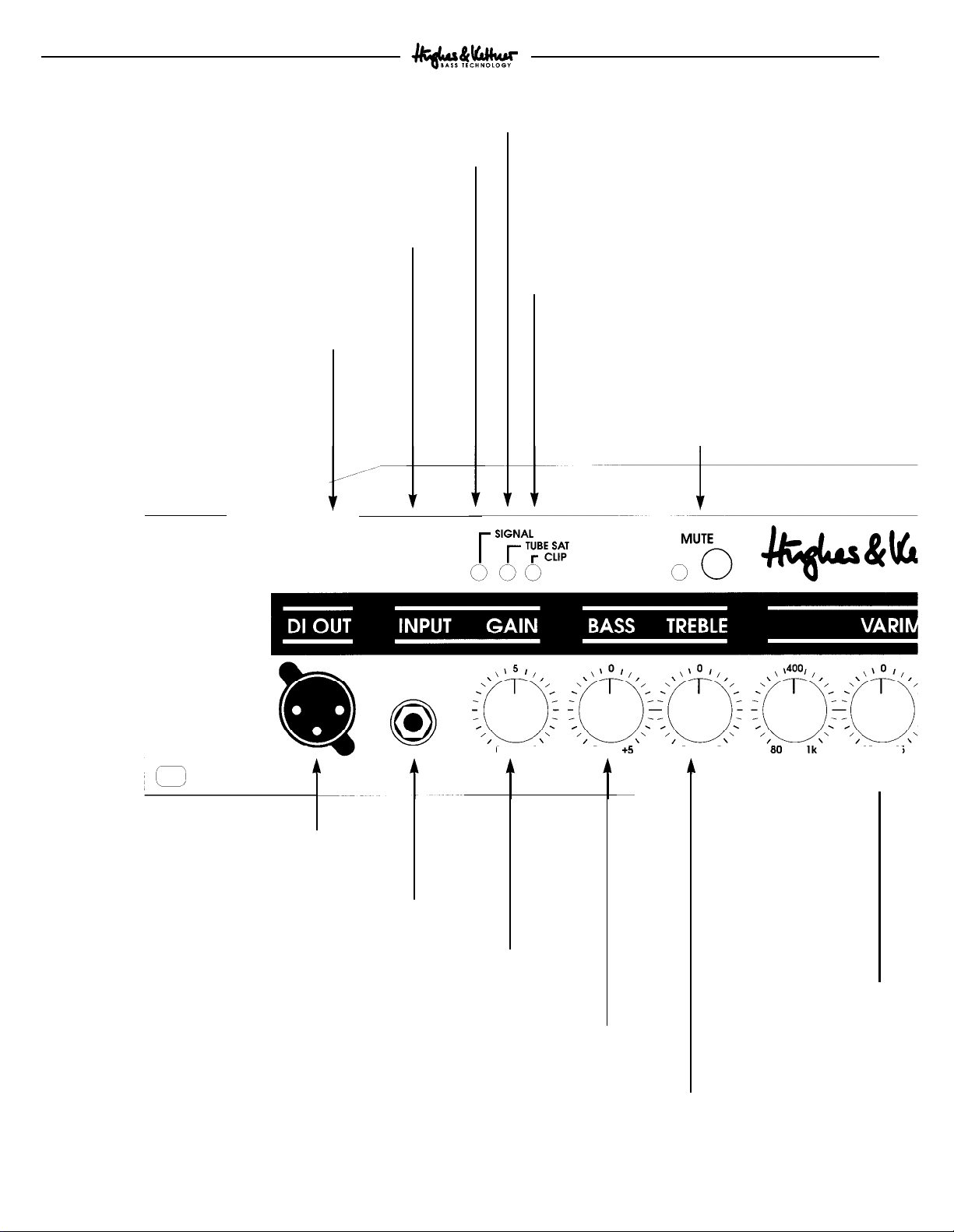
1 .O CONNECTIONS AND CONTROL FEATURES
SIGNAL LED:
instrument signal at the tube stage.
-10 db SWITCH: Lowers the
impedance (e.g. for active instruments).
Indicates the presence of an
BASSBASE'S
DIRECT: Press this button to send the original
instrument signal (unaffected by gain settings,
voicing controls, FX loop and notch filter)
directly to the DI OUT jack, at MIC level.
GROUND LIFT: Removes
the ground from the chassis
at the DI OUT jack.
,/’
,_‘.
,/,’
I
input
TUBE SATURATION LED: Indicates the
preamp is in tube overdrive mode.
CLIP LED: Indicates all types of clipping in the
BASSBASE’s
FX loop distortion). In other words, an illuminated
CLIP LED does not necessarily mean the GAIN
control is set too high, it may also indicate the FX
signal level is not adjusted properly.
MUTE: Switches all of the
except for the TUNER OUT off. Use this button for
breaks between sets, switching instruments, or
when tuning. The RED MUTE LED will illuminate
to indicate the amp is muted.
preamp (including post-EQ section and
BASSBASE
400’s outputs
GRND DIR
00
DI OUT: Use this jack to send signals to a
mixing console or additional power amp.
INPUT
-
Connect your bass to this jack.
CAIN: Controls the input sensitivity and drive
level of the
BASSBASE
BASS: This EQ control defines the bottom end. At the 12 o’clock
position, the signal remains completely unaffected.
dB
-10
0
0
10
preamp.
TREBLE: Use this control to adjust the high end,
particularly the sizzle and overtone range.
-5
-5
+5 -15 +15
FREQ
HZ
t
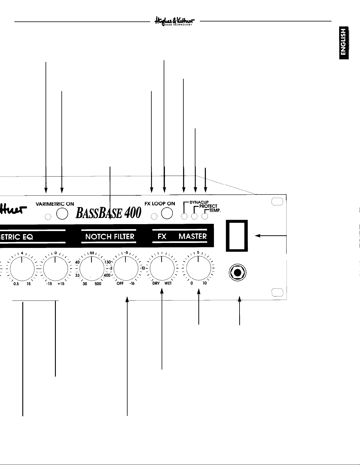
FREQ HZ: Defines
the center frequency
for the
EQ's
section. Please refer
to Section 3.2!
VARIMETRIC -
LOW RANGE
LEVEL: This control adjusts
the level of the frequency
you selected via the FREQ
HZ control. Turn
clockwise to increase,
counter-clockwise to
decrease.
LEVEL
dB
Page 3
BASSBASE
400 - MANUAL
Red VARIMETRIC LED:
Illuminates to indicate
the VARIMETRIC EQ is
active.
VARIMETRIC ON:
Activates the
VARIMETRIC EQ.
NOTCH FILTER: This
adjustable, extremely
narrow-band filter is not
used for normal
shaping, but to suppress
specific stage and room
resonances (e.g. a stage
floor’s sympathetic
vibrations).
FX LOOP ON: Press this button
to activate the E
parallel
FX
BASSBASE 400’s
loop
Green FX LED:
Indicates the FX
loop is active.
sound-
DYNACLIP LED:
Illuminates when the DYNACLIP power
amp circuit is active. DYNACLIP eliminates undesirable
power amp distortion and provides
20% additional
headroom in comparison with conventional power amps.
PROTECT LED: Illuminates when one of the power
amp circuit breakers has tripped. Inadequate
ventilation, a short circuit in the SPEAKER OUTS or
direct current in the output will trigger the circuit
breaker.
TEMP LED: Indicates that thermal overload
(overheating) is the reason why the protective
circuit has activated (e.g. when the ribbed
ventilation duct is obstructed).
,
FREQ
FREQ
KHZ
LEVEL
dB
HZ
FREQ: Use this control
to adjust the notch
filter’s center frequency
within a range of 30 to
500 Hz.
s
LEVEL: T
level of the center frequency you
selected via the FREQ KHZ control.
control adjusts the
CUT
-
MAINS: AC
power switch.
MAINS
dB
MASTER: Controls
the
BASSBASE
overall output.
FX-
MIX : The FX MIX pot adjusts the
balance between the original signal and
the processed signal. DRY = original
signal only, WET = processed signal only.
400’s PHONES: Plug headphones
PHONES
I
with an impedance rating
within the 4-600 ohm range
into this jack.
FREQ KHZ: Defines the center
EQ's
frequency for the
RANGE section.
HI
CUT: Turn this control up to suppress the
frequency you selected via the FREQ
control.
5
Page 4

BASSBASE
400 - MANUAL
REAR PANEL:
FOOTSWITCH VARIMETRIC: Connect a standard single-channel footswitch to this jack. If you use a
HUGHES & KETTNER
FS-1,
its LED will illuminate when you activate the VARIMETRIC EQ.
TUNER OUT: Output jack for an external tuning device.
I
FOOTSWITCH
Connect a standard singlechannel footswitch to this
jack. If you use a HUGHES
&
KETTNER
will illuminate when you
activate the FX LOOP.
FX LOOP:
FS-1,
its LED
MAINS SOCKET:
Connect the included
power cable (Euronorm) to this socket.
The fuse bracket is
integrated in the socket;
make certain you use
specified replacement
fuses only!
LINE OUT: The full-range signal from this jack can be sent
to a mixing console or additional power amp.
RETURN: Connect this jack to the FX processor’s OUTPUT jack.
-
10 db SWITCH: Press this damping switch to
lower the signal level sent to the input of effects
processors expecting an instrument-level signal
such as stomp boxes.
‘t
I
C
SEND: Connect this
jack to the FX
processor’s INPUT jack.
SPEAKER OUTPUTS: Output jacks for connecting external bass speaker cabinets (these jacks
are wired in parallel). The overall impedance rating is 4 ohms. For instance, you can connect
one 500 watt cabinet with a minimum rating of 4 ohms or two 500 watt cabinets with a
minimum rating of 8 ohms each. If you operate the BASSBASE 400 at a higher impedance
rating, power output will decrease accordingly.
It is very important that you heed the maximum rated handling capacity of any speaker
cabinets you choose to connect, especially if you have borrowed them from someone you
want to remain friends with.
Page 5

BASSBASE
400 - MANUAL
2.0 STANDARD SETUP
CABLE CONNECTIONS
/
TUNER
EXTERNAL POWER AMP
FOOTSWITCH
For safety purposes, the
exclusively equipped with
some cases, you may need to employ an adapter cable. The
requisite pin assignments are depicted on the SPEAKER OUT
panel.
NOTE: Under no circumstances should you use
for connecting speaker cabinets to the
are not designed to handle the amount of power this amp
puts out.
3.0 OPERATING THE
BASSBASE
Speaker
BASSBASE
400’s power amp is
and female XLR jacks. In
1/4"
plugs
BASSBASE
400; they
400
3.1 THE INPUT AND BASIC EQ SECTIONS
The response of the
largely on the instrument you are playing, its pickups and
signal level, as well as your playing style. The -10
GAIN controls simplify and significantly expedite your
search for the proper level. Although your ears are the
ultimate authority, the PREAMP
reference tools for this task.
To adjust the gain properly, turn your instrument’s volume all
the way up and spank the plank hard by slapping or really
BASSBASE
400 tube preamp depends
dB
and
LEDs
are also great visual
digging in with your pick. For the ideal setting, the RED CLIP
LED will illuminate briefly on peaks only. If the signal is too
dB
hot, press the -10
NOTE: The RED CLIP LED illuminates to indicate distortion
in the
BASSBASE
or incorrect FX processor levels.
It
will not show distortion caused by your bass, such as an
active instrument’s low batteries.
The yellow TUBE SATURATION LED indicates the
BASSBASE's
will now begin to hear that utterly desirable tube growl and
typical tube compression. For ultraclean sounds, only the
SIGNAL LED should illuminate. If you cannot achieve tube
saturation even with the gain wide open, deactivate the -10
dB button (not depressed).
Use the BASS and TREBLE controls to dial in the basic tone.
Note that the TREBLE control is situated before the tube
stage in the signal chain, yielding smoother harmonic
overtones. If the CLIP LED illuminates when you dial in
higher TREBLE settings, simply adjust the GAIN control to a
lower level.
tube is entering the mellow overdrive zone. You
button to damp it.
400 preamp caused by a saturated input
7
Page 6

BASSBASE
400 - MANUAL
3.2 THE VARIMETRIC
The
BASSBASE
400 VARIMETRIC EQ and FX LOOP can be
EQ
switched via the buttons on the front panel or remotely via
optional footswitches.
NOTE: Please make sure you set the front panel buttons fo
the OFF position (not depressed) when you want to activate
these functions via footswitch.
Handle the VARIMETRIC voicing sections as you would a
semiparametric EQ. The difference lies in the VARIMETRIC
EQ's auto-variable bandwidth and slope, which enable you
to achieve substantially more musical results. The easiest
way to use it (and the best way to acquaint yourself with
how it works) is to do the following:
-
Turn the LEVEL control all the way up so you can really
hear the results when you tune a frequency range in the
lower midrange.
-
Dial in the desired low-mids center frequency via the
FREQ HZ control. (You will hear a wah-wah effect when
turning this knob). If you stop rotating the pot at any point
you will hear that particular frequency especially
pronounced. You may find that a given frequency is
particularly annoying, but not to worry, help is near: simply
attenuate the culprit.
-
You can now use the LEVEL control to amplify/attenuate
selected frequencies as desired.
-
Use the same procedure to tune the upper-mid frequencies
via the FREQ KHZ and LEVEL controls (LEVEL to maximum,
tune FREQ KHZ, then adjust LEVEL to amplify/attenuate the
chosen frequencies.
-
Hit the EQ ON button if you need to compare your
EQed
tone to the basic tone.
-
If you leave the LEVEL control in the 12 o’clock position
for a given frequency, that frequency will not be affected.
With a bit of practice, you can tune an attenuated frequency
range (rather than artificially overemphasizing it first like we
just did), but keep in mind that for the human ear, attenuated
frequencies are generally more diffult to discern.
Why call if "VARIMETRIC" rather than “PARAMETRIC?”
Even though you handle the VARIMETRIC the same way you
would a conventional semi-parametric EQ with its fixed
filtering, it is a much more sophisticated sound-shaping tool.
The filters, rather than the being geared to a fixed frequency
range, are variable, enabling you to fine-tune your tone for a
truly musical result.
LOW/MID VARIMETRIC
20 dB
10 dB
0 dB
-10 dB
-20 dB
80
Hz
160Hz
250 Hz
400 Hz 560 Hz 800 Hz 1 kHz
This frequency diagram depicts the effects of the
VARIMETRIC EQ on the lower-midrange. As clearly
illustrated, the boost of a complete octave range is very
well-
rounded and even, ideal for clearly establishing the basic
sound character. Attenuation occurs at a much narrower
band width allowing you to accurately target undesirable
frequencies. If you amplify a given frequency range, the
frequencies bordering its outer parameters are smoothed out
with a touch of attenuation, and if you attenuate a given
frequency range, the frequencies bordering its outer
parameters are gently amplified, achieving an audio contour
which intensifies the
overall
EQ effect.
HIGH/MID VARIMETRIC
20 dB
10 dB
0 dB
-10 dB
-20 dB
-
0.5
kHz
0,85
kHz
2,5 kHz
kHz
4
6,5
kHz
10 kHz
15
kHz
Higher-midrange equalization: The higher the frequency, the
broader the bandwidth processed by the VARIMETRIC EQ,
much in the way the human ear registers the upper end.
Attenuation occurs at a much narrower band width so you
can accurately target undesirable frequencies and avoid the
dreaded broad-band hollow midrange effect.
Page 7

BASSBASE 400 - MANUAL
3.3 THE NOTCH FILTER
Undesirable frequencies such as those caused by resonant
object in the room or floor boards in the stage can be
suppressed via the NOTCH FILTER. The NOTCH FILTER
operates in extremely narrow bandwidths to avoid altering
the overall sound. Adjust the NOTCH FILTER as follows:
-
Turn the NOTCH FILTER LEVEL control all the way up so
you can clearly hear the attenuated frequency.
-
Turn the FREQUENCY knob until you locate the frequency
responsible for the sympathetic vibrations; the NOTCH
FILTER will suppress it.
-
Now can turn the LEVEL control just below the point
where the resonance sets in, thus ensuring that the filter has
a minimal effect on the overall sound.
It does take a bit of practice to get the hang of the NOTCH
FILTER, as the human ear cannot readily identify attenuated
narrow bandwidths.
-
Adjust the blend between the original and processed
signal via the FX MIX pot located on the front panel
Towards DRY = more original signal, towards WET = more
processed signal.
NOTE: Some signal processors cause phase cancella tions
that are detrimental to the overall sound (washed-out tone,
lower output level at the 12 o’clock position). In this case,
turn the
BASSBASE
FX control all the way to the right
(WET). The effects loop then
operates as a conventional serial loop, i.e. the balance
between the original and the processed signal must be
adjusted at the processor.
TIP 1:
If you choose not to connect a signal processor/effects
device to the FX loop, you can connect another instrument
or
tape
deck at the RETURN jack. For instance you could
connect a guitar, keyboard, drum machine, tape player, etc.
for rehearsals or practice sessions.
-
Connect the additional device as described above and use
the FX-MIX knob as the volume balance control between
your bass and the external signal source.
3.4 THE
The
BASSBASE
BASSBASE
400 AND FX PROCESSORS
400 is equipped with a parallel FX loop. The
processed signal is mixed with the original signal (i.e. the
BASSBASE
preamp signal) so that the original signal is still
audible during the brief interruptions caused by multieffects
processor switching. The FX-MIX knob controls the dry/wet
mix.
NOTE: As a rule of thumb, the best method for using signal
processors is to set the device so that its output is all effect,
then to mix the original signal with the processed signal via
the FX-MIX control. This avoids the tone degradation often
caused by effects devices.
CONNECTING AN FX PROCESSOR:
-
Connect the SEND jack to the processor’s INPUT, and the
RETURN jack to the processor’s output.
-
Activate the FX loop via the FX SELECTOR SWITCH.
-
Adjust the FX loop’s level to your FX processor’s input
level. Press the -10 db button for effects devices that are
designed for instrument levels. If the button is not pushed in,
the signal remains at standard line level for 19”
rackmounted processors.
TIP 2:
Another option is open to you if you do not connect a
signal processor: You can use the loop to activate an
additional MASTER volume for the BASSBASE. To use the FX
MIX control this way:
-
Activate the FX LOOP.
-
Dial in a separate MASTER VOLUME setting via the FX
MIX pot (to the left towards DRY = volume up, to the right
towards WET = volume down).
-
You can switch back and forth between the two MASTER
VOLUMES via the FX footswitch.
NOTE: Please make sure you set the appropriate front panel
button to the OFF position (not depressed) when you want
to activate this function via footswitch.
9
Page 8

BASSBASE
400 - MANUAL
4.0
SERVICE AND PREVENTIVE
MAINTENANCE
The
BASSBASE
many years. Tube fatigue is normal after several thousand
operating hours and becomes apparent through treble loss or
increased microphonics (audible as a ringing noise
reproduced by the tweeter).
Use a soft, slightly damp cloth to clean the
metal parts. Use a brush to clean the flock covering (combo
version).
Avoid exposure to mechanical shocks, extreme heat, dust
and moisture.
400 will not require service of any type for
BASSBASE
400’s
5.0 POSSIBLE ERROR SOURCES/
TROUBLE-SHOOTING
E1)
The
BASSBASE
-
Check the mains cable to see if it is connected properly.
-
The mains fuse is defective. Replace the fuse with another
identical fuse. If this fuse also blows, consult your Hughes &
Kettner dealer.
E2)
The
BASSBASE
audible.
-
The MUTE function is activated. Press the MUTE button!
-
One or several GAIN and MASTER controls are turned all
the way down. Dial in a higher setting.
- The FX-MIX control is turned all the way to WET but you
have not connected a processor to the FX loop. Turn the
MIX knob to DRY.
-
One of the circuit breakers has tripped. Locate and
eliminate the defect (e.g. inadequate ventilation, defective
speaker cable)
-
One of the internal fuses is blown (e.g. caused by a
permanent short in the speaker output jack). Locate and
eliminate the defect and have the fuse changed by a
qualified service technician (make sure the replacement fuse
bears the proper rating).
is not getting any power:
is connected properly, but no sound is
FX-
E3)
Using a footswitch, you are unable to turn off the
VARIMETRIC EQ or the FX LOOP:
-
The EQ or FX LOOP front panel selector switches were
inadvertently left in the ON position. Press the appropriate
selector switch to disengage the front panel control.
E4)
The
sound is thin and muddy when the
FX
processor is
active.
-
The signal processor is causing phase shifting that is being
added to the original signal in the parallel loop. Turn the
FX-MIX control all the way to the right (WET) to avoid phase
cancellations.
E5)
The red CLIP LED keeps illuminating.
-
The
BASSBASE
button or turn your instrument’s volume pot down.
-
The
BASSBASE
GAIN.
-
The
BASSBASE
disconnect the FX processor from the loop. If the CLIP LED
no longer illuminates, you must reduce the processor’s
output level.
E6)
When accessed, the DI OUT jack causes annoying hum.
-
The connected device’s input circuit is unbalanced and an
electrical or magnetic field is causing interference. Use a
balanced input or situate the cables to reduce interference to
a minimum.
-
The grounding of the connected devices are causing a
ground loop. Do not sever the ground of the connected
devices under any circumstances! Activate the GROUND
LIFT SWITCH. If this doesn’t eliminate the noise, you must
ensure the connection is galvanically separated by routing
the signal through a DI box.
400’s input is overloaded. Press the - 10
400 preamp is overloaded. Reduce the
400 FX LOOP is overloaded. Briefly
dB
10
Page 9

BASSBASE
400 - MANUAL
6.0 TECHNICAL DATA
TUBEPREAMP
TUBE TYPE:
PREAMP SECTION
BASS, FREQUENCY:
TREBLE, FREQUENCY:
VARIMETRIC EQ
LO MID, CENTER FREQUENCY:
HI MID, CENTER FREQUENCY:
NOTCHFILTER
CENTER FREQUENCY:
INPUTS
INSTRUMENT:
FX RETURN:
OUTPUTS:
FX SEND:
LINE OUT:
DI
OUT:
TUNER OUT:
ECC83/12AX7A
50 Hz/+15/-10 dB, active
2-20
kHz
+16/-12
dB,
active
Hz, +12/-16 dB,
80-l000
500 Hz -1
5 kHz
30-500 Hz,
-16dB
active
+12/-16 dB active
0 dB/-10 dB 470 kOhms switchable
0
dB /-10 dB
0
db/-10 dB,
0
dB,
-10
-10 dB,‘O
220 Ohms
dB,
200
Ohms,
dB, 4.7 kOhms
47
kOhms,
220 Ohms
balanced
switchable
POWER AMP:
SLEW RATE:
DAMPING FACTOR
FREQUENCY RESPONSE (1 w/
+/-
BANDWIDTH
MINIMUM IMPEDANCE:
INPUT SENSITIVITY:
SPEAKER (Combo)
TYPE:
OVERALL IMPEDANCE:
NOMINAL POWER HANDLING CAPACITY:
SOUND PRESSURE LEVEL 1 W/m
CROSSOVER
CROSSOVER FREQUENCY
ROLL OFF
GENERAL FEATURES
MAX. POWER CONSUMPTION:
MAINS FUSE:
INTERNAL FUSES
Watts
RMS into
396
260 Watts RMS into
612
390
Dynaclipinto 4 Ohms
Watts
Dynaclip
Watts
15 V/us
50Hz: >4000
(4 Ohms)
10 Hz to 60 kHz
20 Hz to 45
kHz
at nominal output
4 Ohms
+3 dBV
&
2x12” Hughes
Kettner Power Pro, 1
8 Ohms
300 Watts RMS
99
dB
kHz
3.5
12
dB/
Oct.
850 VA
230 V
117v/1oov
2 x 1000 mA/SB
2 x 500 mA/SB
1 x 100 mA/SB
4 Ohms (1%THD)
8
Ohms (1% THD)
into 8 Ohms
+/-1 dB
3.15 A/SB
6.3 A/SB
xCD-HF
Horn
WEIGHT AND DIMENSIONS:
Combo
LxHxD:
Weight:
Head
LxHxD:
Weight:
mms
605
approx 115 Ibs., 52 kgs
19”
approx. 33
x 713 mms x 460 mms,
2HU,
lbs.,
12 kgs
11
 Loading...