

Page 1

www.hughes-and-kettner.com
BEDIENUNGSANLEITUNG
HEAD / COMBO
MANUAL
ESPAñOL
ITALIANO
FRANÇAIS
DEUTSCH
2.0
ENGLISH
Page 2

IMPORTANT SAFETY INSTRUCTIONS
BEFORE CONNECTING, READ INSTRUCTIONS
• Read all of these instructions!
• Save these instructions for later use!
• Follow all warnings and instructions marked on the product!
• Do not use this product near water, i.e. bathtub, sink, swimming pool, wet basement,
etc.
• Do not place this product on an unstable cart, stand or table. The product may fall,
causing serious damage to the product or to persons!
• Slots and openings in the cabinet and the back or bottom are provided for ventilation; to ensure reliable operation of the product and to protect it from overheating,
these openings must not be blocked or covered. This product should not be placed
in a built-in installation unless proper ventilation is provided.
• This product should not be placed near a source of heat such as a stove, radiator, or
another heat producing amplifier.
• Use only the supplied power supply or power cord. If you are not sure of the type of
power available, consult your dealer or local power company.
• Do not allow anything to rest on the power cord. Do not locate this product where
persons will walk on the cord.
• Never break off the ground pin on the power supply cord.
• Power supply cords should always be handled carefully. Periodically check cords for
cuts or sign of stress, especially at the plug and the point where the cord exits the
unit.
• The power supply cord should be unplugged when the unit is to be unused for long
periods of time.
• If this product is to be mounted in an equipment rack, rear support should be
provided.
• This product should be used only with a cart or stand that is recommended by
Hughes & Kettner.
• Never push objects of any kind into this product through cabinet slots as they may
touch dangerous voltage points or short out parts that could result in risk of fire or
electric shock. Never spill liquid of any kind on the product.
• Do not attempt to service this product yourself, as opening or removing covers may
expose you to dangerous voltage points or other risks. Refer all servicing to qualified
service personnel.
• Unplug this product from the wall outlet and refer servicing to qualified service
personnel under the following conditions:
• When the power cord or plug is damaged or frayed.
• If liquid has been spilled into the product.
• If the product has been exposed to rain or water.
• If the product does not operate normally when the operating instructions are
followed.
• If the product has been dropped or the cabinet has been damaged.
• If the product exhibits a distinct change in performance, indicating a need of
service!
• Adjust only these controls that are covered by the operating instructions since
improper adjustment of other controls may result in damage and will often require
extensive work by a qualified technician to restore the product to normal operation.
• Exposure to extremely high noise levels may cause a permanent hearing loss.
• Individuals vary considerably in susceptibility to noise induced hearing loss, but
nearly everyone will lose some hearing if exposed to sufficiently intense noise for a
sufficient time. The U.S. Government´s Occupational Safety and Health Administration (OSHA) has specified the following permissible noise level exposures:
Duration Per Day In Hours Sound LeveldBA, Slow Response
• According to OSHA, any exposure in excess of the above permissible limits could
• Ear plug protectors in the ear canals or over the ears must be worn when operating
• Fuses: For continued protection against risk of fire, replace fuses only with the same
TO PREVENT THE RISK OF FIRE AND SHOCK HAZARD, DO NOT EXPOSE THIS APPLIANCE TO
MOISTURE OR RAIN. DO NOT OPEN CASE; NO USER SERVICE-ABLE PARTS INSIDE.
REFER SERVICING TO QUALIFIED SERVICE PERSONNEL.
2
2
890
692
495
397
2 100
11/
2
1 105
1
/
2
1
/
or less 115
4
102
110
result in some hearing loss.
this amplification system in order to prevent a permanent hearing loss if exposure is
in excess of the limits as set forth above. To ensure against potentially dangerous
exposure to high sound pressure levels, it is recommended that all persons exposed
to equipment capable of producing high sound pressure levels such as this amplification system be protected by hearing protectors while this unit is in operation.
type and ratings.
WICHTIGE SICHERHEITSHINWEISE!
BITTE VOR GEBRAUCH LESEN UND FÜR SPÄTEREN GEBRAUCH
AUFBEWAHREN!
• Das Gerät wurde von Hughes & Kettner gemäss IEC 60065 gebaut und hat das Werk in
sicherheitstechnisch einwandfreiem Zustand verlassen. Um diesen Zustand zu erhalten
und einen gefahrlosen Betrieb sicherzustellen, muss der Anwender die Hinweise und die
Warnvermerke beachten, die in der Bedienungsanleitung enthalten sind. Das Gerät entspricht der Schutzklasse I (schutzgeerdet).
• DIE SICHERHEIT, ZUVERLÄSSIGKEIT UND LEISTUNG DES GERÄTES WIRD VON HUGHES &
KETTNER NUR DANN GEWÄHRLEISTET, WENN:
• Montage, Erweiterung, Neueinstellung, Änderungen oder Reparaturen von Hughes &
Kettner oder von dazu ermächtigten Personen ausgeführt werden.
• die elektrische Installation des betreffenden Raumes den Anforderungen von IEC (ANSI)Festlegungen entspricht.
• das Gerät in Übereinstimmung mit der Gebrauchsanweisung verwendet wird.
WARNUNG:
• Wenn Abdeckungen geöffnet oder Gehäuseteile entfernt werden, ausser wenn dies von
Hand möglich ist, können Teile freigelegt werden, die Spannung führen.
• Wenn ein Öffnen des Gerätes erforderlich ist, muss das Gerät von allen Spannungsquellen getrennt sein. Berücksichtigen Sie dies vor dem Abgleich, vor einer Wartung, vor
einer Instandsetzung und vor einem Austausch von Teilen.
• Ein Abgleich, eine Wartung oder eine Reparatur am geöffneten Gerät unter Spannung
darf nur durch eine vom Hersteller autorisierte Fachkraft (nach VBG 4) geschehen, die
mit den verbundenen Gefahren vertraut ist.
• Lautsprecher-Ausgänge, die mit dem IEC 417/5036-Zeichen (Abb.1, s.unten) versehen
sind können berührungsgefährliche Spannungen führen. Deshalb vor dem Einschalten
des Gerätes Verbindung nur mit dem vom Hersteller empfohlenen Anschlusskabel zum
Lautsprecher herstellen.
• Alle Stecker an Verbindungskabeln müssen mit dem Gehäuse verschraubt oder verriegelt
sein, sofern möglich.
• Es dürfen nur Sicherungen vom angegebenen Typ und der angegebenen
Nennstromstärke als Ersatz verwendet werden.
• Eine Verwendung von geflickten Sicherungen oder Kurzschliessen des Halters ist unzulässig.
• Niemals die Schutzleiterverbindung unterbrechen.
• Oberflächen, die mit dem „HOT“-Zeichen (Abb.2, s.unten) versehen sind, Rückwände
oder Abdeckungen mit Kühlschlitzen, Kühlkörper und deren Abdeckungen, sowie Röhren
und deren Abdeckungen können im Betrieb erhöhte Temperaturen annehmen und sollten deshalb nicht berührt werden.
• Hohe Lautstärkepegel können dauernde Gehörschäden verursachen. Vermeiden Sie
deshalb die direkte Nähe von Lautsprechern, die mit hohen Pegeln betrieben werden.
Verwenden Sie einen Gehörschutz bei dauernder Einwirkung hoher Pegel.
NETZANSCHLUSS:
• Das Gerät ist für Dauerbetrieb ausgelegt.
• Die eingestellte Betriebsspannung muss mit der örtlichen Netzspannung übereinstimmen.
• Achtung: Der Netzschalter des Gerätes muss in 0 - Position stehen, wenn das Netzkabel
angeschlossen wird.
• Der Anschluss an das Stromnetz erfolgt mit dem mitgelieferten Netzteil oder Netzkabel.
• Netzteil: Eine beschädigte Anschlussleitung kann nicht ersetzt werden. Das Netzteil darf
nicht mehr betrieben werden.
• Vermeiden Sie einen Anschluss an das Stromnetz in Verteilerdosen zusammen mit vielen
anderen Stromverbrauchern.
• Die Steckdose für die Stromversorgung muss nahe am Gerät angebracht und leicht
zugänglich sein.
AUFSTELLUNGSORT:
• Das Gerät sollte nur auf einer sauberen, waagerechten Arbeitsfläche stehen.
• Das Gerät darf während des Betriebs keinen Erschütterungen ausgesetzt sein.
• Feuchtigkeit und Staub sind nach Möglichkeit fernzuhalten.
• Das Gerät darf nicht in der Nähe von Wasser, Badewanne, Waschbecken, Küchenspüle,
Nassraum, Swimmingpool oder feuchten Räumen betrieben werden. Keine mit Flüssigkeit
gefüllten Gegenstände -Vase, Gläser, Flaschen etc. auf das Gerät stellen.
• Sorgen Sie für ausreichende Belüftung der Geräte.
• Eventuelle Ventilationsöffnungen dürfen niemals blockiert oder abgedeckt werden. Das
Gerät muss mindestens 20 cm von Wänden entfernt aufgestellt werden. Das Gerät darf
nur dann in ein Rack eingebaut werden, wenn für ausreichende Ventilation gesorgt ist
und die Einbauanweisungen des Herstellers eingehalten werden.
• Vermeiden Sie direkte Sonneneinstrahlung sowie die unmittelbare Nähe von Heizkörpern
und Heizstrahlern oder ähnlicher Geräte.
• Wenn das Gerät plötzlich von einem kalten an einen warmen Ort gebracht wird, kann sich
im Geräteinnern Kondensfeuchtigkeit bilden. Dies ist insbesondere bei Röhrengeräten zu
beachten. Vor dem Einschalten solange warten bis das Gerät Raumtemperatur angenommen hat.
• Zubehör: Das Gerät nicht auf einen instabilen Wagen, Ständer, Dreifuß, Untersatz oder
Tisch stellen. Wenn das Gerät herunterfällt, kann es Personenschäden verursachen und
selbst beschädigt werden. Verwenden Sie das Gerät nur mit einem vom Hersteller empfohlenen oder zusammen mit dem Gerät verkauften Wagen, Rack, Ständer, Dreifuß oder
Untersatz. Bei der Aufstellung des Gerätes müssen die Anweisungen des Herstellers
befolgt und muss das vom Hersteller empfohlene Aufstellzubehör verwendet werden.
Eine Kombination aus Gerät und Gestell muss vorsichtigt bewegt werden. Plötzliches
Anhalten, übermässige Kraftanwendung und ungleichmässige Böden können das
Umkippen der Kombination aus Gerät und Gestell bewirken.
• Zusatzvorrichtungen: Verwenden Sie niemals Zusatzvorrichtungen, die nicht vom Hersteller
empfohlen wurden, weil dadurch Unfälle verursacht werden können
• Zum Schutz des Gerätes bei Gewitter oder wenn es längere Zeit nicht beaufsichtigt oder
benutzt wird, sollte der Netzstecker gezogen werden. Dies verhindert Schäden am Gerät
aufgrund von Blitzschlag und Spannungsstössen im Wechselstromnetz.
Abb.1 Abb.2
Page 3

IMPORTANT ADVICE ON SAFETY!
PLEASE READ BEFORE USE AND KEEP FOR LATER USE!
• The unit has been built by Hughes & Kettner in accordance with IEC 60065 and left
the factory in safe working order. To maintain this condition and ensure non-risk
operation, the user must follow the advice and warning comments found in the
operating instructions. The unit conforms to Protection Class 1 (protectively earthed).
• HUGHES & KETTNER ONLY GUARANTEE THE SAFETY, RELIABILITY AND EFFICIENCY OF THE
UNIT IF:
• Assembly, extension, re-adjustment, modifications or repairs are carried out by
Hughes & Kettner or by persons authorized to do so.
• The electrical installation of the relevant area complies with the requirements of IEC
(ANSI) specifications.
•The unit is used in accordance with the operating instructions.
• The unit is regularly checked and tested for electrical safety by a competent
technician.
WARNING:
• If covers are opened or sections of casing are removed, except where this can be
done manually, live parts can become exposed.
• If it is necessary to open the unit this must be isolated from all power sources. Please
take this into account before carrying out adjustments, maintenance, repairs and
before replacing parts.
• Adjustment, maintenance and repairs carried out when the unit has been opened
and is still live may only be performed by specialist personnel who are authorized by
the manufacturer (in accordance with VBG 4) and who are aware of the associated
hazards.
• Loudspeaker outputs which have the IEC 417/5036 symbol (Diagram 1, below) can
carry voltages which are hazardous if they are made contact with. Before the unit is
switched on, the loudspeaker should therefore only be connected using the lead
recommended by the manufacturer.
• Where possible, all plugs on connection cables must be screwed or locked onto the
casing.
• Replace fuses using only those of the specified type and current rating.
• It is not permitted to use repaired fuses or to short-circuit the fuse holder.
• Never interrupt the protective conductor connection.
• Surfaces which are equipped with the „HOT“ mark (Diagram 2, below), rear panels or
covers with cooling slits, cooling bodies and their covers, as well as tubes and their
covers are purposely designed to dissipate high temperatures and should therefore
not be touched.
• High loudspeaker levels can cause permanent hearing damage. You should therefore
avoid the direct vicinity of loudspeakers operating at high levels. Wear hearing
protection if continuously exposed to high levels.
MAINS CONNECTION:
• The unit is designed for continuous operation.
• The set operating voltage must match the local mains supply voltage.
• Caution: The unit mains switch must be in position ‘0’ before the mains cable is
connected.
• The unit is connected to the mains via the supplied power unit or power cable.
• Power unit: Never use a damaged connection lead. Any damage must be rectified
by a competent technician.
• Avoid connection to the mains supply in distributor boxes together with several other
power consumers.
• The plug socket for the power supply must be positioned near the unit and must be
easily accessible.
PLACE OF INSTALLATION:
• The unit should stand only on a clean, horizontal working surface.
• The unit must not be exposed to vibrations during operation.
• Keep away from moisture and dust where possible.
• Do not place the unit near water, baths, wash basins, kitchen sinks, wet areas,
swimming pools or damp rooms. Do not place objects containing liquid on the unit vases, glasses, bottles etc.
• Ensure that the unit is well ventilated.
• Any ventilation openings must never be blocked or covered. The unit must be
positioned at least 20 cm away from walls. The unit may only be fitted in a rack if
adequate ventilation is ensured and if the manufacturer’s installation instructions are
followed.
• Keep away from direct sunlight and the immediate vicinity of heating elements and
radiant heaters or similar devices.
• If the unit is suddenly moved from a cold to a warm location, condensation can form
inside it. This must be taken into account particularly in the case of tube units. Before
switching on, wait until the unit has reached room temperature.
• Accessories: Do not place the unit on an unsteady trolley, stand, tripod, base or table.
If the unit falls down, it can cause personal injury and itself become damaged. Use
the unit only with the trolley, rack stand, tripod or base recommended by the
manufacturer or purchased together with the unit. When setting the unit up, all the
manufacturer’s instructions must be followed and the setup accessories recommended by the manufacturer must be used. Any combination of unit and stand must be
moved carefully. A sudden stop, excessive use of force and uneven floors can cause
the combination of unit and stand to tip over.
• Additional equipment: Never use additional equipment which has not been
recommended by the manufacturer as this can cause accidents.
• To protect the unit during bad weather or when left unattended for prolonged
periods, the mains plug should be disconnected. This prevents the unit being
damaged by lightning and power surges in the AC mains supply.
Diagram 1 Diagram 2
CONSEILS DE SECURITE IMPORTANTS!
PRIERE DE LIRE AVANT L’EMPLOI ET A CONSERVER POUR UTILISATION ULTERIEURE!
• L’appareil a été conçu par Hughes & Kettner selon la norme IEC 60065 et a
quitté l’entreprise dans un état irréprochable. Afin de conserver cet état et
d’assurer un fonctionnement sans danger de l’appareil nous conseillons à l’utilisateur la lecture des indications de sécurité contenues dans le mode d’emploi.
L’appareil est conforme à la classification I (mise à terre de protection).
•SURETE, FIABILITE ET EFFICACITE DE L’APPAREIL NE SONT GARANTIS PAR
HUGHES & KETTNER QUE SI:
• Montage, extension, nouveau réglage, modification ou réparation sont
effectués par Hughes & Kettner ou par toute personne autorisée par
Hughes & Kettner.
• L’installation électrique de la pièce concernée correspond aux normes IEC
(ANSI).
• L’utilisation de l’appareil suit le mode d’emploi.
AVERTISSEMENT:
•A moins que cela ne soit manuellement possible, tout enlèvement ou ouverture
du boîtier peut entrainer la mise au jour de pieces sous tension.
• Si l’ouverture de l’appareil est nécessaire, celui-ci doit être coupé de chaque
source de courant. Ceci est à prendre en considération avant tout ajustement,
entretien, réparation ou changement de pieces.
• Ajustement, entretien ou réparation sur l’appareil ouvert et sous tension ne
peuvent être éffectués que par un spécialiste autorisé par le fabricant (selon
VBG4). Le spécialiste étant conscient des dangers liés à ce genre de
réparation.
• Les sorties de baffles qui portent le signe IEC 417/5036 (fig. 1, voir en bas)
peuvent être sous tension dangereuse. Avant de brancher l’appareil utiliser
uniquement le câble de raccordement conseillé par le fabricant pour
raccorder les baffles.
•Toutes les prises des câbles de raccordement doivent être, si possible, vissées
ou verrouillées sur le boîtier.
• Utilisez subsidiairement uniquement des fusibles de type et de puissance de
courant nominale donnés.
• L’utilisation de fusibles rafistolés ou court-circuites est inadmissible.
• Ne jamais interrompre la connexion du circuit protecteur.
• Il est conseillé de ne pas toucher aux surfaces pourvues du signe „HOT“ (fig. 2,
voir en bas), aux parois arrières ou caches munis de fentes d’aération,
éléments d’aération et leurs caches ansi qu’aux tubes et leurs caches. Ces
éléments pouvant atteindre des températures élévées pendant l’utilisation de
l’appareil.
• Les Niveaux de puissance élévés peuvent entrainer des lésions auditives
durables. Evitez donc la proximité de haut-parleurs utilisés à haute puissance.
Lors de haute puissance continue utilisez une protection auditive.
BRANCHEMENT SUR LE SECTEUR:
• L’appareil est conçu pour une utilisation continue.
• La tension de fonctionnement doit concorder avec la tension secteur locale.
• Attention: L’interrupteur de secteur de l’appareil doit être sur la position „0“,
lorsque le câble de réseau est raccordé.
• Le raccordement au réseau éléctrique s’effectue avec l’adaptateur ou le
cordon d´alimentation livré avec l’appareil.
• Adaptateur: Un câble de raccordement abimé ne peut être remplacé.
L’adaptateur est inutilisable.
• Evitez un raccordement au réseau par des boîtes de distribution surchargées.
• La prise de courant doit être placée à proximité de l’appareil et facile à
atteindre.
LIEU D’INSTALLATION:
• L’appareil doit être placé sur une surface de travail propre et horizontale.
• L’appareil en marche ne doit en aucun cas subir des vibrations.
• Evitez dans la mesure du possible poussière et humidité.
• L’appareil ne doit pas être placé à proximité d’eau, de baignoire, lavabo,
évier, pièce d’eau, piscine ou dans une pièce humide. Ne placez aucun vase,
verre, bouteille ou tout objet rempli de liquide sur l’appareil.
• L’appareil doit être suffisamment aéré.
• Ne jamais recouvrir les ouvertures d’aération. L’appareil doit être placé à 20
cm du mur au minimum. L’appareil peut être monté dans un Rack si une
ventilation suffisante est possible et si les conseils de montage du fabricant
sont suivis.
• Evitez les rayons de soleil et la proximité de radiateurs, chauffages etc.
•Une condensation d’eau peut se former dans l’appareil si celui-ci est transporté
brusquement d’un endroit froid à un endroit chaud. Ceci est particulièrement
important pour des appareils à tubes. Avant de brancher l’appareil attendre
qu’il ait la température ambiante.
• Accessoires: L’appareil ne doit être placé sur un chariot, support, trépied, bâti
ou table instable. Une chute de l’appareil peut entrainer aussi bien des
dommages corporels que techniques. Utilisez l’appareil uniquement avec un
chariot, Rack, support, trépied ou bâti conseillé par le fabricant ou vendu en
combinaison avec l’appareil. Les indications du fabricant pour l’installation de
l’appareil sont à suivre, et les accessoires d’installation conseillés par le
fabricant sont à utiliser. Un ensemble support et appareil doit être déplacé
avec précaution. Des mouvements brusques et des revêtements de sol
irreguliers peuvent entrainer la chute de l´ensemble.
• Equipements supplémentaires: Ne jamais utiliser un équipement supplémentaire
n’ayant pas été conseillé par le fabricant, ceci pouvant entrainer des
accidents.
• Afin de protéger l’appareil pendant un orage ou s’il ne doit pas être utilisé
pendant un certain temps, il est conseillé d’enlever la prise au secteur. Ceci
évite des dommages dûs à la foudre ou à des coups de tension dans le réseau
à courant alternatif.
Fig. 1 Fig. 2
3
3
Page 4

IMPORTANTI AVVERTIMENTI DI SICUREZZA!
Leggere attentamente prima dell’uso e conservare per
un utilizzo successivo:
• L’apparecchio è stato costruito dalla Hughes & Kettner secondo la normativa europea IEC 60065 ed ha lasciato il nostro stabilimento in stato ineccepibile. Per garantire il mantenimento di tale stato e un utilizzo assolutamente privo di rischi l’utente è
tenuto ad osservare le indicazioni e gli avvertimenti di sicurezza contenuti nelle
istruzioni per l’uso. L’apparecchio rispecchia il livello di sicurezza I (collegato a terra).
• Sicurezza, affidabilità e prestazioni dell’apparecchio vengono garantiti dalla Hughes
& Kettner solo ed esclusivamente se:
• Montaggio, ampliamento, rimessa a punto, modifiche e riparazioni vengono
eseguite dalla Hughes & Kettner stessa o da personale da essa autorizzato.
• Gli impianti elettrici nei locali prescelti per l’uso dell’apparecchio rispondono alle
normative stabilite dall’ANSI.
• L’apparecchio viene utilizzato come indicato nel libretto delle istruzioni per l’uso.
Avvertimenti:
• In caso di apertura di parti di rivestimento o rimozione di parti dell’involucro, a meno
che non si tratti di pezzi rimovibili semplicemente a mano, possono venire alla luce
parti dell’apparecchio conduttrici di tensione.
• Se l’apertura dell’apparecchio dovesse risultare necessaria è indispensabile
staccare precedentemente quest’ultimo da tutte le fonti di tensione. Rispettare tale
misura di prevenzione anche prima di un allineamento, di operazioni di manutenzione, della messa in esercizio o della sostituzione di componenti all’interno
dell’apparecchio.
• Allineamento, operazioni di manutenzione o eventuali riparazioni dell’apparecchio
in presenza di tensione vanno eseguite esclusivamente da personale specializzato
ed autorizzato, in grado di eseguire tali operazioni evitandone i rischi connessi.
• Le uscite degli altoparlanti contrassegnate dai caratteri IEC 417/5036 (vedi illustrazione 1 a fondo pag.) possono essere conduttrici di tensione pericolosa con cui
evitare il contatto. Per questo motivo, prima di accendere l’apparecchio, collegare
quest’ultimo agli altoparlanti servendosi esclusivamente del cavetto
d’allacciamento indicato dal produttore.
• Tutte le spine e i cavi di collegamento devono essere avvitati o fissati all’involucro
dell’apparecchio per quanto possibile.
• Tutti i fusibili di sicurezza vanno sostituiti esclusivamente con fusibili del tipo prescritto
e valore della corrente nominale indicato.
• L’utilizzo di fusibili di sicurezza non integri e la messa in corto circuito del sostegno di
metallo sono proibite.
• Non interrompere mai il collegamento con il circuito di protezione.
• Superfici contrassegnate dalla parola „HOT“ (vedi illustrazione 2 a fondo pag.), cosi
come griglie di aerazione, dispositivi di raffreddamento e i loro rivestimenti di
protezione, oppure valvole e i relativi rivestimenti protettivi possono surriscaldarsi
notevolmente durante l’uso e per questo motivo non vanno toccate.
• L’ascolto di suoni ad alto volume può provocare danni permanenti all’udito. Evitate
perciò la diretta vicinanza con altoparlanti ad alta emissione di suono e utilizzate
cuffie protettive in caso ciò non sia possibile.
Alimentazione:
• L’apparecchio è concepito per il funzionamento continuo.
• La tensione di esercizio deve corrispondere alla tensione di rete a cui ci si allaccia.
• Attenzione: l’interruttore di alimentazione dell’apparecchio deve essere in posizione
0 quando viene allacciato il cavetto d’alimentazione.
• L’allacciamento alla rete elettrica avviene tramite alimentatore o cavetto
d’alimentazione consegnato insieme all’apparecchio.
• Alimentatore: un cavo di connessione danneggiato non può essere sostituito.
L’alimentatore non può più essere utilizzato.
• Evitate un allacciamento alla rete di corrente utilizzando cassette di distribuzione
sovraccariche.
• La spina di corrente deve essere situata nelle vicinanze dell’apparecchio e
facilmente raggiungibile in qualsiasi momento.
Locali di collocamento:
• Opportuno collocare l’apparecchio su una superficie pulita e orizzontale.
• Non sottoporre l’apparecchio in funzione a scosse e vibrazioni.
• Proteggere l’apparecchio per quanto possibile da umidità e polvere.
• Non collocare l’apparecchio vicino ad acqua, vasche da bagno, lavandini, lavelli
da cucina, locali umidi o piscine. Non appoggiare recipienti contenenti liquidi - vasi,
bicchieri, bottiglie, ecc. - sull’apparecchio.
• Provvedere ad una buone aerazione dell’apparecchio.
• Eventuali aperture previste per la ventilazione dell’apparecchio non vanno ne
bloccate, ne mai coperte. L’apparecchio va collocato ad almeno 20 cm di
distanza dalle pareti circostanti e può essere inserito tra altre componenti di un
impianto solo in caso di sufficiente ventilazione e qualora le direttive di montaggio
del produttore vengano rispettate.
• Evitare di esporre l’apparecchio ai raggi del sole e di collocarlo direttamente nelle
vicinanze di fonti di calore come caloriferi, stufette, ecc.
• Se l’apparecchio viene trasportato rapidamente da un locale freddo ad uno
riscaldato può succedere che al suo interno si crei della condensa. Ciò va tenuto in
considerazione soprattutto in caso di apparecchi a valvole. Attendere che
l’apparecchio abbia assunto la temperatura ambiente prima di accenderlo.
• Accessori: non collocare l’apparecchio su carrelli, supporti, treppiedi, superfici o
tavoli instabili. Se l’apparecchio dovesse cadere a terra potrebbe causare danni a
terzi o danneggiarsi irreparabilmente. Utilizzate per il collocamento dell’apparecchio
supporti, treppiedi e superfici che siano consigliate dal produttore o direttamente
comprese nell’offerta di vendita. Per il collocamento dell’apparecchio attenetevi
strettamente alle istruzioni del produttore, utilizzando esclusivamente accessori da
esso consigliati. L’apparecchio in combinazione ad un supporto va spostato con
molta attenzione. Movimenti bruschi o il collocamento su pavimenti non piani
possono provocare la caduta dell’apparecchio e del suo supporto.
• Accessori supplementari: non utilizzate mai accessori supplementari che non siano
consigliati dal produttore, potendo essere ciò causa di incidenti.
• Per proteggere l’apparecchio in caso di temporali o nel caso questo non venisse
utilizzato per diverso tempo si consiglia di staccarne la spina di corrente. In questo
modo si evitano danni all’apparecchio dovuti a colpi di fulmine o ad improvvisi
aumenti di tensione nel circuito di corrente alternata.
Illustrazione 1 Illustrazione 2
¡INDICACIONES DE SEGURIDAD IMPORTANTES!
¡LÉANSE ANTES DE UTILIZAR EL APARATO Y GUARDENSE
PARA SU USO POSTERIOR!
• El aparato ha sido producido por Hughes & Kettner según el IEC 60065 y salió de la
fábrica en un estado técnicamente perfecto. Para conservar este estado y asegurar
un funcionamiento sin peligros el usuario debe tener en cuenta las indicaciones y
advertencias contenidas en las instrucciones de manejo. El aparato corresponde a la
clase de protección l (toma de tierra protegida).
• LA SEGURIDAD, LA FIABILIDAD Y EL RENDIMIENTO DEL APARATO SOLO ESTAN
GARANTIZADOS POR HUGHES & KETTNER CUANDO:
• el montaje, la ampliación, el reajuste, los cambios o las reparaciones se realicen por
Hughes & Kettner o por personas autorizadas para ello;
• la instalación eléctrica del recinto en cuestión corresponda a los requisitos de la
determinación del IEC (ANSI);
• el aparato se use de acuerdo con las indicaciones de uso.
ADVERTENCIA:
• Si se destapan protecciones o se retiran piezas de la carcasa, exceptuando si se
puede hacer manualmente, se pueden dejar piezas al descubierto que sean
conductoras de tensión.
• Si es necesario abrir el aparato, éste tiene que estar aislado de todas las fuentes de
alimentación. Esto se debe tener en cuenta antes del ajuste, de un entretenimiento,
de una reparación y de una sustitución de las piezas.
• Un ajuste, un entretenimiento o una reparación en el aparato abierto y bajo tensión
sólo puede ser llevado a cabo por un especialista autorizado por el productor (según
VBG 4) que conozca a fondo los peligros que ello conlleva.
• Las salidas de altavoces que estén provistas de la característica IEC 417/5036 (figura
1, véase abajo) pueden conducir tensiones peligrosas al contacto. Por ello es
indispensable que antes de poner en marcha el aparato; la conexión se haya
realizado únicamente con el cable de empalmes recomendado por el productor.
• Las clavijas de contacto al final de los cables conectores tienen que estar
atornilladas o enclavadas a la carcasa, en tanto que sea posible.
• Los fusibles de repuesto que se utilicen sólo pueden ser del tipo indicado y tener la
intensidad nominal indicada.
• El uso de fusibles reparados o la puesta en cortocircuito del soporte es inadmisible.
• El empalme del conductor de protección no se puede interrumpir en ningún caso.
• Las superficies provistas de la característica "HOT" (figura 2, véase abajo), los
paneles de fondo trasero o las protecciones con ranuras de ventilación, los cuerpos
de ventilación y sus protecciones, así como las válvulas electrónicas y sus
protecciones pueden alcanzar temperaturas muy altas durante el funcionamiento y
por ello no se deberían tocar.
• Niveles elevados de la intensidad de sonido pueden causar continuos daños
auditivos; por ello debe evitar acercarse demasiado a altavoces que funcionen a
altos niveles. En tales casos utilice protecciones auditivas.
ACOMETIDA A LA RED:
• El aparato está proyectado para un funcionamiento continuo.
• La tensión de funcionamiento ajustada tiene que coincidir con la tensión de la red
del lugar.
• Advertencia: el interruptor de la red del aparato tiene que estar en la posición 0
cuando se conecte el cable de red.
• La conexión a la red eléctrica se efectuará con la fuente de alimentación o con el
cable de red que se entreguen con el aparato.
• Fuente de alimentación: una linea de conexión dañada no se puede sustituir. La
fuente de alimentación no puede volver a ponerse en funcionamiento.
• Evite una conexión de la red eléctrica a distribuidores con muchas tomas de
corriente.
• El enchufe para el suministro de corriente tiene que estar cerca del aparato y ser de
fácil acceso.
SITUACION:
• El aparato debería estar situado en una superficie limpia y totalmente horizontal.
• El aparato no puede estar expuesto a ningún tipo de sacudidas durante su
funcionamiento.
• Se deben evitar la humedad y el polvo.
• El aparato no puede ponerse en funcionamiento cerca del agua, la bañera, el
lavamanos, la pila de la cocina, un recinto con tuberías de agua, la piscina o en
habitaciones húmedas. Tampoco se pueden poner objetos llenos de líquido - jarrones,
vasos, botellas, etc. - encima de él.
• Procure que el aparato tenga suficiente ventilación.
• Las aberturas de ventilación existentes no se deben bloquear ni tapar nunca. El
aparato debe estar situado como mínimo a 20 cm de la pared. El aparato sólo se
puede montar en un rack, si se ha procurado la suficiente ventilación y se han
cumplido las indicaciones de montaje del productor.
• Evite los rayos del sol directos así como la proximidad a radiadores, electroradiadores o aparatos similares.
• Si el aparato pasa repentinamente de un lugar frío a otro caliente, se puede
condensar humedad en su interior. Esto se debe tener en cuenta sobretodo en los
aparatos con válvulas electrónicas. Antes de poner en marcha el aparato se debe
esperar hasta que éste haya adquirido la temperatura ambiental.
• Accesorios: el aparato no se puede colocar encima de carros, estantes, trípodes,
soportes o mesas inestables. Si el aparato se cae puede causar daños personales y se
puede estropear. Coloque el aparato sólo en un carro, rack, estante, trípode o
soporte recomendado por el productor o que se le haya vendido junto con el aparato. En la instalación se deben seguir las indicaciones del productor así como utilizar los
accesorios recomendados por el mismo para colocarlo encima. El conjunto del
aparato con el pedestal se debe mover con mucho cuidado. Un paro brusco, la
aplicación de una fuerza desmesurada o un suelo irregular puede ocasionar la caida
de todo el conjunto.
• Piezas adicionales: no utilice nunca piezas adicionales que no estén recomendadas
por el productor, ya que se podrían provocar accidentes.
• Para protejer el aparato de una tormenta o si no se supervisa ni utiliza durante algún
tiempo, se debería desconectar la clavija de la red. Así se evitan daños en el aparato
a causa de un rayo y golpes de tensión en la red de corriente alterna.
Figura 1 Figura 2
4
4
Page 5

WARP 7 - MANUAL
WE ARE DELIGHTED THAT YOU OPTED
FOR A HUGHES & KETTNER®WARP 7™!
21st century metal is all about detuned guitars,
ponderous & ominous riffs, big & bold effected
clean sounds. No wonder that yesteryear’s
amplification can’t cut it in this brave new world
of sound. The WARP 7™ is designed specifically to
do the sound, vibe and feel of detuned guitars
justice. No quarter expected, none granted. The
WARP channel will hammer out every hard-as-nails
riff you send its way. Its CLEAN channel also packs
a mighty wallop; even the wildest effect sounds
slice through loud and clear. Both channels sport
dedicated 3-band EQs, letting you dial in great
tone and extreme contrasts, from nasty, paintpeeling riffs to glassy & glossy clean arpeggios
and chord work. With its beefy 100-watt power
amp, the WARP 7™ is the ideal tool for winning
friends and influencing people; particularly your
neighbors and parents are sure to be delighted.
The combo is loaded with Celestion®Hot 100
speakers and the 4x 12"cabinet with Celestion
RockDriver Junior speakers. Both are powerhouse
setups that your musical message across most
emphatically!
CONTENTS
THINGS TO DO BEFORE OPERATING THE AMP . . . . . . . .5
1.0 THE CHANNELS OF THE WARP 7™ . . . . . . . . . . . . . .6
2.0 CONNECTIONS AND CONTROL FEATURES . . . . . . .7
3.0 STANDARD SETUP / CABLE CONNECTIONS . . . . . . .8
4.0 OPERATING THE WARP 7™ . . . . . . . . . . . . . . . . . . . .8
4.1 SELECTING CHANNELS . . . . . . . . . . . . . . . . . . . . . . .8
4.2 THE WARP 7™ AND FX DEVICES . . . . . . . . . . . . . . . .8
4.3 THE WARP 7™ AND AUXILIARY POWERAMPS . . . . . .9
4.4 THE WARP 7™ AND MIXING CONSOLES . . . . . . . . .9
5.0 SERVICE AND PREVENTIVE MAINTENANCE . . . . . . . .9
6.0 POSSIBLE ERROR SOURCES/TROUBLE-SHOOTING . . .9
7.0 TECHNICAL SPECIFICATIONS . . . . . . . . . . . . . . . . . .10
THINGS TO DO BEFORE OPERATING THE AMP
You’re probably champing at the bit, impatient to
plug in and pound out your first riff. Before you do,
though, be sure to read these guidelines
thoroughly. They have been known to ensure
long life for many an amp.
• Check out the voltage rating displayed next to
the WARP 7™'s MAINS INPUT and make sure it
matches your local mains current before you
plug in.
• Make sure plenty of air can circulate around
your amp's ventilation ducts.
HERE’S WISHING YOU LOTS OF SUCCESS
AND FUN WITH THE TONE OF YOUR
WARP 7™!
• Place the amp on a sturdy, secure base and
avoid exposing it to mechanical shocks and
extreme temperatures that could endanger the
device or your and others' safety.
• The manufacturer disclaims any liability or
responsibility whatsoever for any damage or
defect to this and other devices resulting from
misuse.
5
5
ENGLISH
Page 6

WARP 7 - MANUAL
1.0 THE CHANNELS OF THE WARP 7™
What’s so special about the design of the
WARP 7™ circuitry?
Well, there are two new wrinkles particularly worth
noting:
1) The preamp is optimized for the signal and
frequency response of detuned guitars. The
WARP 7™ just starts to unleash the brunt of its
sonic fury at frequencies other amps can’t even
begin to render. This big bad beast likes the
taste of detuned riffs best, so be sure to feed it
regularly!
2) WARP 7™ sports two channels that are, sonically
speaking, polar opposites: ultra clean vs.
roaring high gain tone. And that calls for closer
examination:
CLEAN:
The CLEAN channel delivers razor-sharp tone
piercing enough to stop a charging rhino in its
tracks at a hundred paces. The signal remains
distortion-free even at a very high volume. Not
until the Volume knob is cranked to the hilt will the
amp begin to bare its teeth with a hint of snarl.
Nice but nasty are the adjectives that come to
mind.
Now what’s so remarkable about that? In a
nutshell, you can lather the wildest and weirdest
effects on your guitar signal and it will still cut
through loud and clear, with enough punch to put
the rest of the band’s instruments in their place.
Say goodbye and good riddance to those wimpy,
washed-out sounds. Now you can play with the
big boys’ toys - hip vibe, roto and tremolo effects
of the variety used by the headlining acts - and
still be heard at denture-rattling volume levels.
WARP:
CAUTION! This is the WARP 7™’s sonic heart of
darkness. This channel offers the kind of earsplitting
high gain sound that you have come to know and
love from your fave CDs. Its distortion can be best
be described as a throaty rumble - picture a
genetically engineered, steroid-addled lion with
an attitude problem. Depending on the setting, it
delivers a nasty nu metal thump, post-grunge
growl, alternative snarl or the doomsday thunder
so cherished by devotees of death and Goth
metal. The Presence knob tweaks the upper mids
to suit each genre. Case in point: Gain all the way
up, Bass cranked, Mid and High to 12 o'clock
positions, Presence to 11 o'clock – presto, there’s
that trademark "Bizkit" sound. Now you have some
idea of what the WARP 7™ is able to deliver in
terms of tone. But there’s more to it than that you’ll find truckloads of our trademark Technology
of Tone in the various connectors, buttons and
knobs as well. And that’s our cue to look at these
in detail:
6
6
Page 7
WARP 7 MANUAL
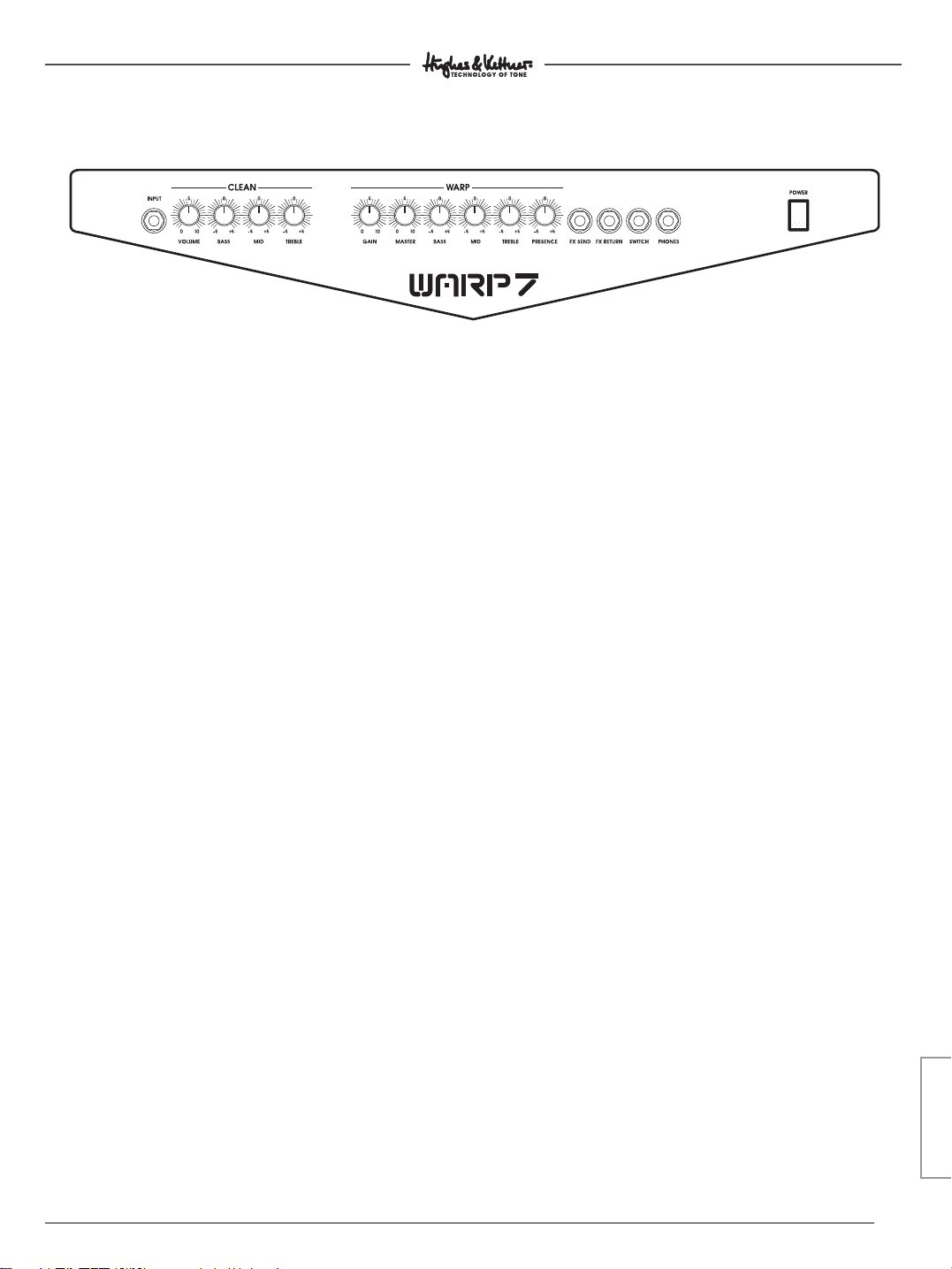
2.0 CONNECTIONS AND CONTROL FEATURES
INPUT: Input jack for guitars. It input sensitivity is
designed to take guitars with even very high
output levels, so feel free to slap this input silly with
powerful signals. Totally bulletproof (in this respect,
that is), it is built to take everything your guitar can
dish out and more.
CLEAN VOLUME: Determines the level of the
CLEAN channel. Even at high settings, the amp’s
output signal will remain virtually free of distortion.
You may want to take pity on your band mates
and hand out earplugs before the next rehearsal.
BASS, MID, TREBLE: The CLEAN channel’s 3-band
EQ. Again, this channel has oodles of headroom,
delivering tremendous clarity and packing the
kind of punch it takes to get heavily processed
signals across load and clear. If you don’t use
many effects, you’ll come up with the best results
if you turn the BASS knob well up and the TREBLE
knob to just to the left of the 12 o’clock position.
Then adjust the MID knob to tune the tone to your
guitar and taste.
YELLOW WARP LED: Illuminates to indicate the
CLEAN channel is active.
WARP GAIN: Controls the WARP channel’s
saturation level. This knob is your grit selector: Go
from merely dirty but tremendously punchy tone
at lower settings to an evil roar at higher GAIN
settings.
WARP MASTER: Controls the level of the WARP
channel; use it to dial in the desired balance between the CLEAN and WARP channels. If you want
to send your band buddies home with bleeding
ears, this is the knob to use. Witticisms aside,
though: The WARP 7™ is a truly loud amp and your
hearing is extremely sensitive. Please use common
sense and exercise restraint with volume levels
BASS, MID, TREBLE: 3-band EQ for the WARP
channel. You’ll find an example setting in section
2.0 above describing the WARP channel.
PRESENCE: Fine-tunes the upper mids (1,100 to
1,800 hertz). This frequency range has a
considerable influence on the overall flavor of
your sound. The amount of “bite” varies
depending on this knob’s setting. With a little
experimentation, this knob will soon help you
discover the sonic secrets of the big boys.
CHANNEL SELECT: Switches from the CLEAN
channel to the WARP channel. The WARP channel
is active when the pushbutton is pressed.
RED WARP LED: Illuminates to indicate the WARP
channel is active.
FX-SEND: If you want to employ an effect device,
connect this jack to the signal processor’s input.
(More on this in section 4.2). You can also use this
output to send the signal to another power amp
or a RED BOX®for the purposing of patching your
signal into a mixer. (More on this in section 4.3)
FX-RETURN: Connect this jack to the effect
device’s output.
7
7
ENGLISH
Page 8
WARP 7 - MANUAL
FUSE
SPEAKER OUTS
100 WATTS
4 - 8 OHMS
SPEAKER OUTS
100 WATTS
4 - 8 OHMS
Head version Combo version
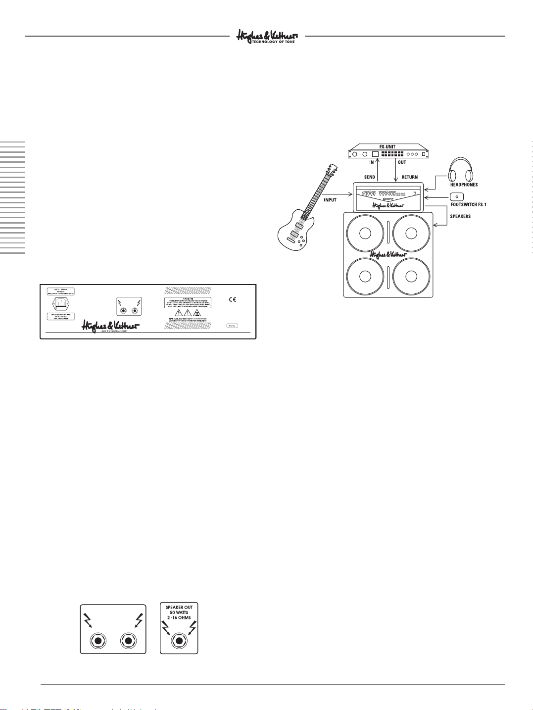
FOOTSWITCH: Jack designed to take a standard
footswitch (the HUGHES & KETTNER®FS-1 will do
nicely) for switching back and forth between the
CLEAN and WARP channels. To do this, the
CHANNEL SELECT switch on the front panel must
be set to CLEAN (red LED does not light up).
PHONES: Connect headphones to this jack.
The head’s SPEAKER OUT is automatically
disconnected when you insert a plug into this jack.
On the combo, both the SPEAKER OUT and
internal speaker are disabled, ensuring
conciliatory relationships with landlords.
REAR PANEL:
MAINS: Connect the included Euro norm mains
cable to this socket. Before you plug in the mains
cord, ensure your local mains voltage matches
the specification indicated on the device.
3.0 STANDARD SETUP /
CABLE CONNECTIONS
HEAD/COMBO:
4.0 OPERATING THE WARP 7™
Now that you know a bit about the key features,
let’s take a look at how the WARP 7™ handles. This
section also provides useful tips on connecting the
WARP 7™ to other devices.
SPEAKER OUTPUTS:
Serial (combo): Designed to connect an auxiliary
cabinet with a minimum impedance of 4 ohms.
Unless of course you want to use the WARP 7™
one last time as a hot air grill, barbecuing it in the
process. That’s an option we can’t advocate...
Parallel (heads): Designed to connect to the
included 4x12" cabinet and another auxiliary
cabinet with a rating of at least 8 ohms. The
minimum permissible impedance is 4 ohms. This
means if you connect cabinets to both outs, each
cabinet’s impedance may be no lower than
4 ohms! Unless of course…(see above)
8
8
4.1 SELECTING CHANNELS
You can activate the channels of the WARP 7™
via the front panel CHANNEL SELECT button or an
external footswitch. The HUGHES & KETTNER®range
of accessories offers a footswitch that fits the bill,
the FS 1.
4.2 THE WARP 7™ AND FX DEVICES
WARP 7™ is equipped with a serial effects loop.
This means that the preamp output signal is routed
through an inserted effect device in its entirety,
and that the entire signal is processed. Please
note that the sound quality of the processed
signal depends largely on the quality of the
employed effect device. A sorry signal processor
can corrupt your tone.
Page 9

WARP 7 - MANUAL
HOW TO CONNECT AN EFFECTOR:
• Connect the FX SEND jack to the input and the
FX RETURN jack to the output of your effects
device.
• Use high-quality patch cords only to avoid signal
loss, background noise and drop-outs.
• Ensure that the effect device is not being overdriven. Keep an eye on whatever type of level
meter, gain indicator or overload lamp the
effects device is equipped with, and adjust its
input and output controls accordingly.
• Unless you have a jones of lo-fi effects, distortion
devices simply don’t belong in an FX loop. Any
kind of device that compresses the signal should
be connected first in the signal chain.
Depending on the type of effect you want to
achieve, it may be preferable to plug a
compressor to the amp's input.
• Other stompboxes should also be plugged into
the front panel input.
4.3 THE WARP 7™ AND AUXILIARY
POWERAMPS
Connect FX-SEND (+ 6 dB output level with the
power amp’s line input. This port’s output level is
independent of the MASTER volume knob. -Again,
use high-quality patch cords only to avoid signal
loss, background noise and drop-outs.
4.4 THE WARP 7™ AND MIXING CONSOLES
When you want to connect the WARP 7™ to a
mixer, we recommend that you patch the signal
through a HUGHES & KETTNER®RED BOX®PRO first.
Connect it to the amp’s FX SEND jack. Here too,
the output level is independent of the MASTER
knob setting. The RED BOX® balances the signal
and simulates the sound of speakers. A RED BOX
may also be inserted between the speaker out
and the speakers. In this scenario, the output level
depends on the MASTER knob setting.
®
5.0 SERVICE AND PREVENTIVE
MAINTENANCE
The WARP 7™ amp does not require any type of
regular maintenance, and there are no userserviceable parts inside. However, there are a few
precautions you would be well-advised to take
because they will extend the life of your amp
tremendously:
• Make sure all peripheral devices, cords and cables
are in a state of good repair!
• Defective speaker cables (shorted cables, loose
connections) are by far the most common cause of
power amp failure.
• Low-quality patch cords lack adequate shielding;
they are noisy and often the source of annoying hum.
• Ensure plenty of air can circulate around your amp's
ventilation areas (that is, the back of the amp‘s
chassis) at all times.
• Definitely avoid exposure to mechanical shocks and
extreme heat, dust and particularly moisture.
• Be picky about the kind of peripheral devices that
you connect to your amp and always check out their
specs before you plug them in. Never connect
devices with high output signal levels (e.g. power
amps) to your amp's input.
• Be sure the AC power source delivers the current that
your amp is designed to handle before you plug it in.
When in doubt about the local rating, ask the venue's
sound technician or a stage hand.
• Refrain from DIY repairs! Be sure to take your to an
experienced technician when internal fuses need
replacing.
Use a soft damp cloth to clean the exterior surface of
the WARP 7™.
6.0 POSSIBLE ERROR SOURCES/
TROUBLE-SHOOTING
6.1 The WARP 7™ won’t power up when you
switch it on:
• It‘s not getting AC power. Check the mains
cable to see if it‘s connected properly!
• The mains fuse is defective. Replace it another
fuse bearing the identical rating. If another
defect occurs, please get in touch with your
local HUGHES & KETTNER dealer.
ENGLISH
9
9
Page 10
WARP 7 - MANUAL
6.2 The WARP 7™ is cabled up and connected
properly, but no sound is audible:
• One or several GAIN or MASTER controls is/are
turned all the way down. Dial in a higher setting.
• Your guitar cord may be defective; try another
cord.
• A short circuit in the speaker signal chain may
have tripped an internal fuse. Make sure none of
the connections are shorted out and have a
qualified service technician replace the fuse.
6.3 Your footswitch will not switch channels:
• The footswitch cord’s plug is not inserted pro-
perly into the jack,
• Check if you connected a suitable footswitch.
We recommend the FS-1, another great product
of the HUGHES & KETTNER®range of accessories.
6.4 When in use, the FX-SEND / FX-RETURN jacks
generate annoying hum:
• An electrical or magnetic field is causing inter-
ference. Use cables of a higher quality or
rearrange the cables you are using to reduce
interference to a minimum. If this still doesn't
improve the situation, use a DI box.
• The connected devices’ ground circuit may be
causing a ground loop. At least one device’s
connection must be galvanically using a DI box
or transformer.
CAUTION: Under no circumstances should you
sever the ground of the connected devices!
7.0 TECHNICAL SPECIFICATIONS
Preamp section:
INPUT: -10 dB/1 m ohms
FX SEND: +6 dBV/270 ohms
FX RETURN: 0 dB/220 ohms
Power amp:
'CURRENT FEEDBACK' solid state power amp
Output power: 100 watts RMS at 4 ohms
(2x 12” combo and head)
80 watts RMS at 4 ohms
(1x 12” combo)
Headphones out: 100 mW at 4 – 600 ohms
Frequency response: 20 Hz - 30 kHz
Combos:
Celestion
Speaker Cabinet:
4 CELESTION RockDriver 12”Junior speakers
200 watts RMS at 8 ohms
GENERAL DATA:
Voltage: 230 V~ (European model)
Max. power consumption:
175 VA at 4 ohms
Mains fuse:
T 500 mA (230 V model)
T 1000 mA (117 V model)
T 1000 mA (100 V model)
Internal fuses: 2x T2A
®
Hot 100 1x 12” and 2x 12” versions
117 V~ (North American model)
100 V~ (Japanese model)
6.5 The signal is totally distorted when you
connect an FX device (even when you dial in
a clean sound).
• The effector’s input is being overdriven.
Decrease the processor‘s input sensitivity by
backing off its input or gain knob.
6.6 The output signal level drops considerably
when you connect an effect device.
• The FX processor's output level is set to too low a
level. Turn it up
10
10
Dimensions (W x H x D):
1x 12” Combo: 590 x 500 x 320 mm
2x 12 Combo”: 654 x 565 x 330 mm
Head: 610 x 235 x 255 mm
Speaker cabinet: 765 x 825 x 345 mm
Weight:
1x 12” Combo: 20 kg
2x 12 Combo: 26 kg
Head: 9 kg
Speaker cabinet: 38 kg
Page 11

WARP 7 MANUAL
WIR FREUEN UNS, DASS DU DICH FÜR
EINEN HUGHES & KETTNER®WARP 7™
ENTSCHIEDEN HAST!
Das Soundverständnis im Metal des 21. Jahrhunderts wird von heruntergestimmten Gitarren,
bösartigen Riffs und wabernden, cleanen
Effektklängen geprägt. Klar, dass in dieser neuen
Soundwelt auch die Amps von gestern versagen.
Der WARP 7™ ist auf den Sound von “detuned”
Gitarren spezialisiert. Im WARP Kanal prügelt er
ultratiefe hammerharte Riffs gnadenlos heraus.
Sein CLEAN Kanal wurde so abgestimmt, dass sich
selbst die abgefahrensten Effektsounds im
Bandgefüge noch klar durchsetzen. Beide Kanäle
haben ihren eigenen 3Band EQ. So lässt sich der
WARP 7™ optimal für das krasse Wechselspiel von
bösen Riffs und gläsernen Cleansounds einstellen.
Mit seiner 100 Watt Endstufe eignet sich der
WARP 7™ ganz hervorragend dafür, sich bei
Nachbarn und Eltern mit Nachdruck beliebt zu
machen. Nicht ganz unschuldig daran sind die
Celestion®Hot 100 Speaker beim Combo, und die
Celestion®RockDriver Junior beim 4x 12“ Cabinet.
Das rumpelt so richtig fett!
INHALT
VOR DER INBETRIEBNAHME . . . . . . . . . . . . . . . . . . . . . .11
1.0 DIE KANÄLE DES WARP 7™ . . . . . . . . . . . . . . . . . .12
2.0 ANSCHLÜSSE UND BEDIENELEMENTE . . . . . . . . . . . .13
3.0 STANDARD SET UP/VERKABELUNG . . . . . . . . . . . . .14
4.0 BEDIENUNG DES WARP 7™ . . . . . . . . . . . . . . . . . .14
4.1 DAS ANWÄHLEN DER KANÄLE . . . . . . . . . . . . . . . .14
4.2 DER WARP 7™ MIT EFFEKTGERÄTEN . . . . . . . . . . . .14
4.3 DER WARP 7™ MIT ZUSÄTZLICHER ENDSTUFE . . . . .14
4.4 DER WARP 7™ AM MISCHPULT . . . . . . . . . . . . . . . .15
5.0 WARTUNG UND SERVICE . . . . . . . . . . . . . . . . . . . . .15
6.0 FEHLERBESEITIGUNG/TROUBLESHOOTING . . . . . . . .15
7.0 TECHNISCHE DATEN . . . . . . . . . . . . . . . . . . . . . . . .16
VOR DER INBETRIEBNAHME
Sicher willst Du jetzt gleich den ersten Riff
schrubben. Aber vorher solltest Du dies hier genau
durchlesen - das hat schon so manchem Amp ein
langes Leben beschert.
• Vergewissere Dich vor dem Anschluss des
WARP 7™, dass der am MAINS INPUT angegebene Spannungswert mit der ortsüblichen
Netzspannung übereinstimmt.
• Stelle eine ausreichende Luftzufuhr zu den
Kühlflächen des Gerätes sicher
VIEL ERFOLG UND SPASS AM ”TONE”
MIT DEINEM WARP 7™!
• Achte auf einen festen Stellplatz, der mechanische und thermische Fremdeinwirkungen,
welche die Betriebssicherheit des Gerätes oder
die Sicherheit von Personen beeinträchtigen
könnten, ausschließt.
• Für Schäden am Gerät oder anderer Geräte, die
durch unsachgemäßen Betrieb entstehen, wird
seitens des Herstellers keine Haftung übernommen.
11
11
DEUTSCH
Page 12

WARP 7 - MANUAL
WARP 7 - MANUAL
1.0 DIE KANÄLE DES WARP 7™
Was ist so besonders am Schaltungskonzept des
WARP 7™?
Nun, da gibt es zwei herausragende
Eigenschaften:
1) Die Vorstufe ist auf das Signal und den
Frequenzgang von heruntergestimmten
Gitarren optimiert. Wo andere Amps nicht hinkommen, geht der WARP 7™ erst so richtig ab.
“Detuned” schmeckt diesem Amp am besten.
Füttere ihn also regelmäßig!
2) Der WARP 7™ verfügt über zwei Kanäle, die
gegensätzlicher kaum sein können. Ultra-clean
trifft auf brüllendes High Gain. Werfen wir einmal
einen genauen Blick darauf.
CLEAN:
Der CLEAN Kanal liefert einen schneidenden Ton,
mit dem Du jedem, der in den Bannstrahl des
WARP 7™ gerät, messerscharf den Scheitel ziehen
kannst. Selbst bei hohem Volume bleibt das Signal
unverzerrt. Erst bei nahezu voll aufgedrehtem
Regler geht der Sound in einen leichten Crunch
über. Und was ist der Clou daran? Ganz einfach:
Du kannst den Sound mit den verrücktesten und
abgedrehtesten Effekten verfremden; er wird sich
immer noch glasklar gegen den Rest der Band
durchsetzen statt mulmig unterzugehen. Endlich
werden die coolen Vibe-, Roto-, Tremolo-Effekte,
die Du bei den großen Bands gehört hast, auch
für Dich in amtlicher Lautstärke realisierbar.
WARP:
ACHTUNG! Hier schlägt das böse Herz des
WARP 7™. Dieser Kanal bietet den brüllenden High
Gain Sound, den Du von Deinen Lieblings-CD´s her
kennst. Die Verzerrung lässt sich am besten mit
einem grollenden RRrrrrrrrr beschreiben. Je nach
Einstellung brettert dieser Kanal in bester Nu Metal
Manier daher, bewegt sich im Post-Grunge und
Alternative Sektor oder donnert knallhart durch
Death- und Gothic-Gefilde. Der PRESENCE Regler
liefert dabei immer die entsprechende
Feinabstimmung für die oberen Mitten.
Ein Beispiel: GAIN fast voll auf, BASS rein, MID und
TREBLE auf 12 Uhr Position, PRESENCE auf 11 Uhr
und schon steht ein “Bizkit”-Sound, der sich gewaschen hat. OK, jetzt haben wir also schon einmal
einen groben Überblick über die Grundsounds des
WARP 7™. Aber natürlich steckt auch in den einzelnen Anschlüssen, Schaltern und Reglern eine
ganze Menge Technology of Tone. Schauen wir
uns die einmal im Detail an:
12
12
Page 13

WARP 7 MANUAL
2.0 ANSCHLÜSSE UND BEDIENELEMENTE
INPUT: Anschlussbuchse für die Gitarre. Die Eingangsempfindlichkeit ist so ausgelegt, das der INPUT auch
Gitarren mit enorm hohem Output verträgt. Du
kannst den Amp also ruhig mit Vollgas ansteuern. Er
ist in dieser Hinsicht absolut kugelsicher.
CLEAN VOLUME: Regelt die Lautstärke des CLEAN
Kanals. Selbst bei hohen Einstellungen bleibt der
Sound nahezu unverzerrt. Deine Bandkollegen sollten
also schon mal die Ohrenstöpsel für die nächste
Probe bereit legen.
BASS, MID, TREBLE: 3Band Klangregelung für den
CLEAN Kanal. Wie bereits erwähnt, verfügt dieser
Kanal über enorm viel Biss, um dem Ton auch beim
Einsatz stark verfremdender Effekte die nötige
Durchsetzungskraft zu geben. Falls Du nicht so viele
Effekte einsetzt, erhältst Du die besten SoundResultate, wenn Du den BASS Regler ziemlich weit
aufdrehst und den TREBLE Regler etwas unter der
12 Uhr Position einstellst. Mit dem MID Regler kannst
Du den Sound dann ganz gezielt auf Deine Gitarre
und Deine Vorstellungen abstimmen.
GELBE WARP LED: Die leuchtende LED zeigt den
aktiven CLEAN Kanal an.
CHANNEL SELECT: Schaltet zwischen dem CLEAN
Kanal und dem WARP Kanal um. Bei gedrücktem
Schalter ist der WARP Kanal aktiv (Siehe auch
FOOTSWITCH).
ROTE WARP LED: Die leuchtende LED zeigt den
aktiven WARP Kanal an.
WARP GAIN: Kontrolliert den Übersteuerungsgrad des
WARP Kanals. Hier befindet sich die Schaltzentrale
des Bösen. Bei niedrigeren Einstellungen entwickelt
der Sound einen enormen Bumms, um bei höheren
GAIN Settings immer heftiger zu rollen.
WARP MASTER: Regelt die Lautstärke des WARP
Kanals im Verhältnis zum CLEAN Kanal. Wenn Du
Deine Band mit blutenden Ohren nach Hause
schicken willst, ist das der richtige Knopf dafür. Jetzt
mal im Ernst: Der WARP 7™ ist ein verdammt lauter
Amp und Dein Gehör ein sensibles Sinnesorgan. Ein
vernünftiger Umgang mit der Lautstärke ist also
durchaus angebracht.
BASS, MID, TREBLE: 3-Band Klangregelung für den
WARP Kanal. Einen Vorschlag für ein Setting findest
Du oben unter 2.0 bei der Beschreibung des WARP
Kanals.
PRESENCE: Liefert die Feinabstimmung für den
Bereich der oberen Mitten (1100 – 1800 Hz) und
verleiht dem Sound so seinen ganz typischen
Charakter. Je nach Einstellung erhält der Ton mehr
oder weniger Biss. Durch etwas Experimentieren wirst
Du ganz schnell den Sounds der Großen auf die
Schliche kommen.
FX-SEND: Falls Du ein Effektgerät verwenden
möchtest, so verbinde diese Buchse mit dem
Eingang des Effektgerätes (Mehr zu diesem Thema
findest Du unter 4.2) Weiterhin ist hier der Anschluss
einer zusätzliche Endstufe (siehe Punkt 4.3) oder einer
RED BOX
lich. (Mehr zu diesem Thema findest Du unter 4.4)
FX-RETURN: Verbinde diese Buchse mit dem Ausgang
des Effektgerätes.
®
zwecks Signalführung zum Mischpult mög-
13
13
DEUTSCH
Page 14

WARP 7 - MANUAL
FUSE
SPEAKER OUTS
100 WATTS
4 - 8 OHMS
SPEAKER OUTS
100 WATTS
4 - 8 OHMS
Head version Combo version
WARP 7 - MANUAL
FOOTSWITCH: Anschluss für einen handelsüblichen
Fußschalter (z.B. Hughes & Kettner
®
FS-1). Damit kann
zwischen CLEAN und WARP Kanal umgeschaltet werden. Der CHANNEL SELECT Schalter auf der Frontseite
muss dabei auf CLEAN geschaltet sein (gelbe LED
leuchtet).
PHONES: Klinkenbuchse zum Anschluss eines
Kopfhörers. Bei Verwendung eines Kopfhörers wird
der SPEAKER OUT (Topteil), bei den Combos die internen Speaker und der externe SPEAKER OUT stumm
geschaltet. Somit dürfte auch der sorgenfreie
Umgang mit dem Vermieter gesichert sein.
RÜCKSEITE:
MAINS: Netzbuchse für das mitgelieferte EuroNetzkabel. Bevor der Netzstecker eingesteckt wird,
vergewissere Dich, dass die ortsübliche Netzspannung mit der auf dem Gerät angegebenem
Wert übereinstimmt.
3.0 STANDARD SET UP /
VERKABELUNG
HEAD/COMBO:
4.0 BEDIENUNG DES WARP 7™
So, die wichtigsten Features haben wir ja nun kennengelernt. Nachfolgend gibt es nun noch ein
paar nützliche Infos über die Verbindung des
WARP 7™ mit anderen Geräten.
SPEAKER OUTPUTS:
Seriell bei den Combos, zum Anschluss einer
Zusatzbox mit einer Mindestimpedanz von 2 Ohm. Es
sei denn natürlich, Du möchtest den WARP 7™ in
einem allerletzten Einsatz als Heißluftgrill benutzen...
Würden wir nicht so gut finden...
Parallel bei den Tops, zum Anschluss der mitgelieferten 4x 12” Box und einer anderen Zusatzbox mit
mindestens 8 Ohm. Die Gesamtimpedanz von 4 Ohm
darf nicht unterschritten werden. Das heißt, bei
Belegung beider Buchsen dürfen nur Boxen mit je
8 Ohm angeschlossen werden. Es sei denn
natürlich....s. o.
14
14
4.1 DAS ANWÄHLEN DER KANÄLE
Die Kanäle des WARP 7™ werden über den CHAN-
NEL SELECT Schalter auf der Frontseite oder einen
externen Fußschalter angewählt. Ein geeigneter
Fußschalter (FS-1) wird im Zubehörprogramm von
Hughes & Kettner®angeboten.
4.2 DER WARP 7™ MIT EFFEKTGERÄTEN
Der WARP 7™ ist mit einem seriellen Effektweg aus-
gestattet. Dabei wird das Vorstufensignal des
Amps komplett durch ein eingeschliffenes
Effektgerät geführt und bearbeitet. Beachte bitte,
dass die Soundqualität entscheidend von der
Qualität des verwendeten Effektgerätes abhängt.
Ein schlechter Effektprozessor kann den Sound so
richtig kaputt machen.
Page 15

WARP 7 MANUAL
ANSCHLUSS DES EFFEKTGERÄTES:
• Verbinde die FX-SEND Buchse mit dem Input,
und die FX-RETURN Buchse mit den Output
Deines Effektgerätes.
• Verwende ausschließlich hochwertige
Patchkabel, um Signalverluste, Störgeräusche
oder Aussetzer zu vermeiden.
• Achte stets darauf, dass das Effektgerät nicht
übersteuert wird. Beachte dazu ggf. die
Aussteuerungsanzeige des Effektgerätes und
benutze die ”Input” und ”Output” Regler am
Effektgerät zum Auspegeln.
• ”Verzerrer” haben im Einschleifweg nichts zu
suchen. Auch Kompressoren sollten (je nach
gewünschtem Soundeffekt) ggf. vor den Input
des Amps geschaltet werden.
• Auch andere Fußpedale sollte man vor den
Input schalteten.
4.3 DER WARP 7™ MIT ZUSÄTZLICHER
ENDSTUFE
Verbinde die FX-SEND Buchse (Ausgangspegel
+6 dB) mit dem LINE INPUT der Endstufe. Der
Ausgangspegel ist masterunabhängig.
• Verwende auch hier ausschließlich hochwertige
Patchkabel, um Signalverluste, Störgeräusche
oder Aussetzer zu vermeiden.
4.4 DER WARP 7™ AM MISCHPULT
Zum Anschluss des WARP 7™ an ein Mischpult
empfehlen wir die Signalführung über eine
Hughes & Kettner®RED BOX®PRO. Diese kann an
der FX-SEND Buchse des Amps angeschlossen
werden. Der Ausgangspegel ist hier ebenso
masterunabhängig. Das Signal ist dann
symmetrisch ausgeführt (= balanced) und mit
einer Speakersimulation versehen. Die RED BOX
PRO kann allerdings auch zwischen Speakerausgang und Lautsprecherbox geschaltet
werden. In diesem Fall ist das Signal von der
MASTER Stellung abhängig.
®
5.0 WARTUNG UND SERVICE
Der WARP 7™ ist wartungsfrei. Dennoch gibt es
einige Grundregeln, deren Einhaltung die
Lebensdauer Deines Amps enorm verlängern.
• Sorge immer für eine technisch einwandfreie
Geräteperipherie!
• Defekte Boxenkabel sind mit Abstand die
häufigste Ursache für Endstufenausfälle.
• Schlechte Patch-Kabel führen wegen ihrer mangelhaften Schirmung immer wieder zu
Brummproblemen.
• Sorge stets für freie Luftzirkulation an den u die
Spezifikationen von Zusatzgeräten. Schließe nie
Ausgänge mit zu großem Pegel (z.B. Endstufen)
an den Amp an.
• Prüfe vor Anschluss des Gerätes immer die vorhandene Netzspannung. Kontaktiere im Zweifelsfall den Bühnentechniker, Hausmeister o.ä.
• Versuche keine ”do it yourself” Reparaturen!
Auch der Tausch interner Sicherungen muss von
einem erfahrenen Techniker vorgenommen
werden.
Die Oberfläche des WARP 7™ lässt sich am besten
mit einem leicht angefeuchteten Tuch säubern.
6.0 MÖGLICHE FEHLERQUELLEN /
TROUBLESHOOTING
6.1 Der WARP 7™ lässt sich nicht einschalten:
• Es liegt keine Netzspannung an. Überprüfe den
korrekten Anschluss des Netzkabels!
• Die Netzsicherung ist defekt. Bitte ersetze die
Netzsicherung durch eine neue Sicherung mit
dem gleichen Wert. Bei einem erneutem Defekt
wende Dich bitte an Deinen Hughes & Kettner
Fachhändler.
®
DEUTSCH
15
15
Page 16

WARP 7 - MANUAL
WARP 7 - MANUAL
6.2 Der WARP 7™ ist korrekt verkabelt, aber es ist
nichts zu hören:
• Einer oder mehrere der GAIN- bzw. MASTER-
Regler sind zugedreht. Drehe den/die Regler
auf. Das Gitarrenkabel ist evtl. nicht in Ordnung.
Probiere es mit einem anderen.
• Durch einen Kurzschluss am
Lautsprecheranschluss hat sicher, dass die Anschlüsse kurzschlussfrei sind und lasse die Sicherung durch einen Servicetechniker wechseln.
6.3 Die Kanäle können über einen externen
Fußschalter nicht umgeschaltet werden:
• Der Stecker des Fußschalters ist nicht korrekt
eingesteckt.
• Prüfe, ob der angeschlossene Fußschalter dem
richtigen Typ entspricht. Wir empfehlen den FS-1
aus dem Hughes & Kettner®Zubehörprogramm.
6.4 Beim Benutzen der FX-SEND / FX-RETURN
Buchse entsteht ein Brummgeräusch:
• Ein elektrisches / magnetisches Wechselfeld
streut auf die Leitung ein. Benutze ein besseres
Kabel und versuche durch geschicktes Verlegen
der Leitung die Einstreuung zu minimieren.
Hilft dies nicht, empfiehlt sich die Benutzung
einer DI Box.
• Über die Erdung der verbundenen Geräte
entsteht eine Brummschleife. Mindestens eine
Verbindung der Geräte muss mit einer DI Box
oder Übertrager galvanisch getrennt werden.
ACHTUNG: Unterbreche in keinem Fall die
Schutzleiter der Geräte
7.0 TECHNISCHE DATEN
Vorstufensektion:
INPUT: -10 dB/1 Mohm
FX-SEND: +6 dBV/270 Ohm
FX-RETURN: 0 dB/220 Ohm
Endstufe:
'CURRENT FEEDBACK' Halbleiterendstufe
Ausgangsleistung:
100 Watt RMS an 4 Ohm (2x 12“Combo und Topteil)
80 Watt RMS an 4 Ohm (1x 12“Combo)
Kopfhörerausgang: 100 mW an 4 – 600 Ohm
Frequenzgang: 20 Hz - 30 Khz
Combos: Celestion® Hot 100 beim 1x 12“
und 2x 12“ Speaker
Cabinet: 4x CELESTION® RockDriver Junior,
12”, 200 Watt RMS an 8 Ohm
ALLGEMEINE DATEN:
Betriebsspannung:
230 V~ (europäisches Modell)
117 V~ (nordamerikanisches Modell)
100 V~ (japanisches Modell)
Max. Leistungsaufnahme: 175 VA
Netzsicherung: T 500 mA (230 V Modell)
T 1000 mA (117 V Modell)
T 1000 mA (100 V Modell)
Interne Sicherungen: 2x T2A
Abmessungen (B x H x T):
Combo 1x 12“: 590 x 500 x 320
Combo 2x 12“: 654 x 565 x 330
Topteil: 610 x 235 x 255 mm
Cabinet: 765 x 825 x 345 mm
6.5 Beim Anschluss eines Effektgerätes ist das
Signal (selbst bei Clean Sounds) völlig verzerrt.
• Der Eingang des Effektgerätes wird übersteuert.
Regle die Eingangsempfindlichkeit (”Input” oder
”Gain”) am Effektgerät zurück.
6.6 Beim Anschluss eines Effektgerätes wird das
Ausgangssignal deutlich leiser.
• Das Effektgerät ist an seinem Ausgang falsch
ausgepegelt. Regele den ”Output” am
Effektgerät hoch.
16
16
Gewicht:
Combo 1x 12“: 20 kg
Combo 2x 12“: 26 kg
Topteil: 9 kg
Cabinet: 38 kg
Page 17

WARP 7 MANUAL
NOUS VOUS FÉLICITONS D'AVOIR CHOISI
LE HUGHES & KETTNER WARP 7TM!
Le son Metal du 21e siècle est l'apanage des
guitares « detuned », des riffs agressifs et des effets
clean empreints de vibrato. Il est clair que, dans
ce nouvel environnement sonore, les amplis d'hier
ne vous sont plus d'aucune utilité. Le WARP 7TMest
spécialisé dans le son des guitares « detuned ».
Le canal WARP résonne aux martèlements
impitoyables des riffs profonds. Grâce au réglage
de son canal CLEAN, les effets sonores les plus
discrets parviennent encore à s'exprimer
clairement au sein du groupe. Les deux canaux
sont dotés de leur propre égaliseur 3 bandes. Le
WARP 7TMpeut ainsi être réglé de façon optimale
pour reproduire les alternances marquées entre
riffs rageurs et sons clean cristallins. Avec son
étage de puissance de 100 watts, le WARP 7TMest
idéal pour la tranquillité des voisins et des parents.
Avec son Celestion®Hot 100 (pour le combo) et
son Celestion®RockDriver Junior (pour les hautparleurs 4 x 12"), il sait parfaitement ce qu'il fait.
Sans aucun doute, il « déménage » !
NOUS VOUS SOUHAITONS BEAUCOUP DE
SUCCÈS ET DE PLAISIR MUSICAL AVEC
VOTRE WARP 7TM!
SOMMAIRE
AVANT LA MISE EN FONCTION . . . . . . . . . . . . . . . . . . .17
1.0 LES CANAUX DU WARP 7™ . . . . . . . . . . . . . . . . . .18
2.0 RACCORDEMENTS ET ÉLÉMENTS DE COMMANDE .19
3.0 RÉGLAGES STANDARD ET CÂBLAGE . . . . . . . . . . . .20
4.0 COMMANDE DU WARP 7™ . . . . . . . . . . . . . . . . . .20
4.1 LE CHOIX DES CANAUX . . . . . . . . . . . . . . . . . . . . .20
TM
4.2 LE WARP 7
4.3 LE WARP 7
SUPPLÉMENTAIRE . . . . . . . . . . . . . . . . . . . . . . . . . . .21
4.4 LE WARP 7
5.0 ENTRETIEN ET MAINTENANCE . . . . . . . . . . . . . . . . .21
6.0 DÉPISTAGE DES PANNES . . . . . . . . . . . . . . . . . . . . .21
7.0 CARACTÉRISTIQUES TECHNIQUES . . . . . . . . . . . . . .22
AVANT LA MISE EN FONCTION
Vous êtes certainement impatient de gratter votre
premier riff. Cependant, nous vous conseillons de
commencer par lire attentivement les pages qui
suivent. Elles ont déjà eu l'occasion de prolonger
la vie de plus d'un ampli.
• Avant de brancher le WARP 7
vérifier que la valeur de tension indiquée près
de la prise de branchement (MAINS INPUT)
correspond bien à la tension secteur disponible.
• Veillez à garantir une aération suffisante des
surfaces de refroidissement de l'appareil.
• Installez l'appareil dans un endroit stable, à
l'abri des influences mécaniques et thermiques
extérieures susceptibles de compromettre la
sécurité de fonctionnement de l'appareil ou la
sécurité des personnes.
• Le fabricant décline toute responsabilité en cas
de dégâts causés à l'appareil ou à d'autres
appareils qui résulteraient d'une utilisation
inappropriée.
ET LES UNITÉS D'EFFETS . . . . . . . . . . . . .20
TM
AVEC UN ÉTAGE DE PUISSANCE
TM
À LA TABLE DE MIXAGE . . . . . . . . . . .21
TM
, n'oubliez pas de
FRANÇAIS
17
17
Page 18

WARP 7 - MANUAL
WARP 7 - MANUAL
1.0 LES CANAUX DU WARP 7™
En quoi le concept de circuit du WARP 7TMest-il
différent ?
En fait, il se distingue par deux propriétés
remarquables :
1) Le préampli est optimisé en fonction du signal
et de la réponse harmonique des guitares «
detuned ». Le WARP 7TMse sent seulement à l'aise
là où d'autres amplis jettent l’éponge. «
Detuned », voilà ce qu'il préfère. Par
conséquent, n'hésitez pas à lui en donner !
2) Le WARP 7TMest doté de deux canaux on ne
peut plus différents : Ultra-clean et High Gain.
Nous vous devons peut-être une petite
explication :
CLEAN:
Le canal CLEAN produit un son incisif qui décoiffe.
Le signal reste clair sur presque toute la plage de
puissance sonore et ne génère un léger crunch
qu'à fond. Le summum ? Très simple : vous pouvez
greffer sur le son les effets les plus fous et les plus
tordus ; il ne sera jamais éclipsé par le reste du
groupe, mais restera toujours aussi clair. Enfin, les
effets cool du type Vibe, Roto et Trémolo, dont
vous gratifient les grands groupes, seront aussi «
dans vos cordes ».
WARP:
ATTENTION ! C'est ici que bat le cœur agressif du
WARP 7TM. Ce canal produit un rugissement High
Gain qui vous rappellera immanquablement vos
CD favoris. Pour décrire la distorsion, rien de tel
qu'un bon RRrrrrrrrr qui gronde. Selon le réglage,
ce canal vous emportera aux rythmes brutaux du
New Metal ou aux coups de tonnerre du Death
ou du Gothic, mais il se sentira aussi à l'aise dans
le style Post Grunge ou Alternative. Le potentiomètre de Présence garantit toujours le réglage
fin approprié pour les médiums supérieurs. Un
exemple : Gain presque à fond, basses claires,
médiums et aigus sur « 12 heures », Presence sur «
11 heures » et vous obtenez un son « Bizkit ». OK,
vous avez maintenant une bonne idée du son de
base du WARP 7TM. Mais il est clair que les différents
raccords, commutateurs et potentiomètres
recèlent un véritable trésor de la Technology of
Tone. Nous vous invitons à les passer en revue :
18
18
Page 19

WARP 7 MANUAL
2.0 RACCORDEMENTS ET ÉLÉMENTS DE COMMANDE
INPUT : prise pour guitare. La sensibilité d'entrée est
telle qu'elle supporte également les guitares à fort
output. Ne craignez pas de pousser l'ampli dans
ses derniers retranchements, il est absolument
inébranlable.
CLEAN VOLUME : réglage du volume du canal
CLEAN. Même à fond, le son ne subit pratiquement pas de distorsions. Les autres musiciens du
groupe auront tout intérêt à prévoir des boules
Quiès pour la prochaine répétition.
BASS, MID, TREBLE : réglage de sonorité à trois
bandes pour le canal CLEAN. Comme nous
l'avons déjà expliqué, ce canal possède une
agressivité suffisante pour s'imposer, quels que
soient les effets utilisés. Si vous n'êtes pas un fana
des effets, nous vous conseillons de mettre le
potentiomètre BASS presque à fond et le potentiomètre TREBLE sur « 12 heures ». Le potentiomètre
MID vous permet alors d'adapter le son à votre
guitare et à votre jeu.
DEL JAUNE WARP : la DEL s'allume pour indiquer
que le canal CLEAN est actif.
CHANNEL SELECT : commutation entre les canaux
CLEAN et WARP. Le canal WARP est actif quand il
est enfoncé.
DEL ROUGE WARP : la DEL rouge s'allume pour
indiquer que le canal WARP est actif.
WARP GAIN : contrôle du taux de surmodulation
(la distorsion, le facteur RRrrrrrr) du canal WARP.
C'est ici que se trouve la centrale de commuta-
tion de l'agressivité. Sur les premiers niveaux de
réglage, le son génère un énorme boum, qui
s'amplifie lorsqu’on augmente le réglage.
WARP MASTER : régulation du volume sonore du
canal WARP par rapport au canal CLEAN. Si votre
objectif est de percer les tympans de tous les
autres membres du groupe, c'est assurément la
fonction à utiliser. Soyons sérieux : le WARP 7TMest
un ampli diablement puissant et vos oreilles sont
des organes sensoriels sensibles. Réglez le volume
dans des limites raisonnables !
BASS, MID, TREBLE : réglage de sonorité à trois
bandes pour le canal WARP. Pour un exemple de
réglage, reportez-vous à la section 2.0 (description
du canal WARP).
PRÉSENCE : réglage fin pour les médiums
supérieurs (1 100 – 1 800 Hz), qui confère son
caractère typique au son. Le son est plus ou moins
agressif selon le réglage. Après quelques tâtonnements, vous découvrirez rapidement le son des
plus grands.
FX-SEND : si vous comptez utiliser une unité
d'effets, reliez son entrée à cette prise (pour plus
d’informations à ce sujet, consultez la section 4.2).
En outre, vous pouvez aussi brancher un étage de
puissance supplémentaire (voir la section 4.3) ou
un RED BOX®afin d'acheminer les signaux à la
table de mixage (pour de plus d’informations à
ce sujet, consultez la section 4.4).
FX-RETURN : reliez la sortie de l'unité d'effets à
cette prise.
FRANÇAIS
19
19
Page 20

WARP 7 - MANUAL
FUSE
SPEAKER OUTS
100 WATTS
4 - 8 OHMS
SPEAKER OUTS
100 WATTS
4 - 8 OHMS
Head version Combo version
WARP 7 - MANUAL
PÉDALIER : prise pour un pédalier classique (par
exemple, Hughes & Kettner“ FS-1) permettant de
commuter entre les canaux CLEAN et WARP. Le
commutateur CHANNEL SELECT de la face avant
doit être réglé sur CLEAN (DEL jaune allumée).
PHONES : douille jack pour casque. L'utilisation
d'un casque coupe automatiquement le SPEAKER
OUT (head) ; sur un combo, les haut-parleurs
internes et le SPEAKER OUT externe sont coupés.
Cela évite tout conflit avec votre entourage.
FACE ARRIÈRE :
MAINS : prise pour câble secteur conforme aux
normes européennes compris dans la livraison.
Avant de brancher le câble secteur, assurez-vous
que la tension indiquée sur l'appareil correspond
bien à la tension secteur disponible.
Speaker Outputs :
Série pour combos, pour le branchement d'une
enceinte supplémentaire présentant une
impédance minimale de 4 ohms. Sauf si, bien
évidemment, vous avez envie de transformer le
WARP 7TMen barbecue... Ce que nous trouverions
moins intéressant...
Parallèle pour heads, pour le branchement de
l'enceinte 4x12" (comprise dans la livraison) et
d'une enceinte supplémentaire présentant une
impédance minimale de 8 ohms. L'impédance
minimale admissible est de 4 ohms. Cela signifie
que, si les deux prises sont occupées, seules des
enceintes de 8 ohms chacune peuvent être raccordées. Sauf si, bien évidemment, vous avez
envie de transformer le WARP 7TMen
barbecue... Ce que
nous trouverions
moins intéressant...
20
20
3.0 RÉGLAGES STANDARD ET
CÂBLAGE
HEAD/COMBO:
4.0 COMMANDE DU WARP 7™
Voilà, nous vous avons présenté les principales
fonctions du WARP 7TM. Vous trouverez ci-après
quelques informations utiles sur le raccordement
du WA RP 7TMà d'autres appareils.
4.1 LE CHOIX DES CANAUX
La sélection des canaux du WARP 7TMs’effectue
au moyen du commutateur CHANNEL SELECT situé
sur la face avant ou d'un pédalier externe. Vous
trouverez un pédalier idéal (FS-1) dans la liste
d'options de Hughes & Kettner®.
4.2 LE WARP 7TM ET LES UNITÉS D'EFFETS
Le WA RP 7TMest équipé d'une boucle d'effets série.
Le signal préamplifié de l'ampli passe intégralement par une unité d'effets incorporée où il est
traité. N'oubliez pas que la qualité de l'unité
d'effets utilisée a une influence déterminante sur
la qualité du son. Un processeur d'effets de piètre
qualité peut donner un son relativement mièvre.
Page 21

WARP 7 MANUAL
Connexion de l'unité d'effets :
• Reliez la prise FX-SEND à l'entrée (Input) et la
prise FX-RETURN à la sortie (Output) de votre
unité d'effets.
• Utilisez exclusivement des câbles de raccordement de qualité afin d'éviter les pertes de
signaux, les bruits parasites ou toute autre forme
de décrochage.
• Veillez toujours à éviter les distorsions dans l'unité
d'effets. Observez si nécessaire l'indicateur de
modulation de l'unité d'effets et utilisez les
potentiomètres « Input » et « Output » de l'unité
d'effets pour équilibrer votre réglage.
• Les « générateurs de distorsions » n'ont rien à
chercher dans la boucle d'effet. En principe, les
effets de compression apparaissent toujours au
début de la chaîne de signaux. Le cas échéant,
les compresseurs doivent eux aussi (selon l'effet
sonore cherché) être branchés en amont de
l'entrée de l'amplificateur.
• Des pédaliers supplémentaires doivent également être branchés en amont de l'entrée.
4.3 LE WARP 7TMAVEC UN ÉTAGE DE
PUISSANCE SUPPLÉMENTAIRE
Branchez la prise FX-SEND (niveau de sortie + 6 dB)
à la LINE INPUT de l'étage de puissance. Le niveau
de sortie est indépendant du Master.
• Ici aussi, utilisez exclusivement des câbles de
raccordement de qualité afin d'éviter les pertes
de signaux, les bruits parasites ou toute autre
forme de décrochage.
5.0 ENTRETIEN ET MAINTENANCE
L'ampli WARP 7TMne nécessite aucun entretien.
Néanmoins, vous allongerez sensiblement la durée de
vie de votre ampli en respectant quelques règles
élémentaires.
• Utilisez toujours des appareils périphériques en parfait
état de marche !
• Les câbles de haut-parleur défectueux constituent de
loin la cause la plus fréquente de panne des étages
de puissance. Des câbles défectueux provoquent
toujours des problèmes de ronflement.
• Des câbles de raccordement de piètre qualité
provoquent toujours des ronflements en raison de leur
blindage insuffisant.
• Veillez toujours à maintenir les fentes d'aération des
surfaces de refroidissement de l'ampli (arrière du
châssis de l'ampli) dégagées.
• En tout état de cause, évitez d'exposer l'appareil à
des vibrations mécaniques, des chaleurs extrêmes,
des poussières et – surtout – de l'humidité.
• Soyez particulièrement vigilant en ce qui concerne les
spécifications des appareils supplémentaires. Ne
branchez jamais de sorties à niveau trop élevé (par
exemple, des étages de puissance) à l'ampli.
• Vérifiez toujours la tension secteur avant de brancher
l'appareil. En cas de doute, contactez le technicien
de scène, le responsable de la salle, etc.
• Ne « bricolez » pas de réparations vous-même en cas
de problème ! Même pour le remplacement de
fusibles internes, il est préférable de faire appel à un
technicien qualifié. Il est conseillé de nettoyer la
surface du WARP 7
humide.
TM
avec un chiffon légèrement
6.0 DÉPISTAGE DES PANNES
FRANÇAIS
4.4 LE WARP 7TMÀ LA TABLE DE MIXAGE
Si vous raccordez le WARP 7TMà une table de
mixage, nous vous recommandons d'utiliser un
Hughes & Kettner“ RED BOX®PRO pour
l'acheminement des signaux. Celui-ci peut être
connecté à la prise FX-SEND de l'ampli. Le niveau
de sortie est ici aussi indépendant du Master. Le
signal est symétrisé (= balanced) et est doté d'une
simulation d'enceinte. Toutefois, le RED BOX®peut
aussi être inséré entre la sortie haut-parleur et
l'enceinte. Dans ce cas, le signal est dépendant
du MASTER.
6.1 Impossible d’allumer le WARP 7TM:
• L'ampli n'est pas alimenté. Vérifiez si le câble
secteur est bien raccordé !
• Le fusible secteur est défectueux. Remplacez-le
par un fusible de même valeur. En cas de
nouveau problème, contactez votre revendeur
Hughes & Kettner®.
21
21
Page 22

WARP 7 - MANUAL
WARP 7 - MANUAL
6.2 Le WARP 7TMest câblé correctement, mais
aucun son n'est audible :
• Un ou plusieurs potentiomètres GAIN ou MASTER
sont sur 0. Tournez le ou les boutons de réglage.
• Le câble de la guitare est peut-être défectueux.
Essayez avec un autre câble.
• Un court-circuit dans le branchement du haut-
parleur a fait déclencher un des fusibles
internes. Vérifiez l'absence de court-circuit dans
les branchements et appelez un technicien du
service après-vente pour remplacer le fusible.
6.3 Il est impossible de passer d'un canal à l'autre
au moyen d'un pédalier externe :
• Le pédalier n'est pas raccordé correctement.
• Vérifiez que le pédalier raccordé correspond
bien au type de pédalier requis. Nous
recommandons le pédalier FS-1 de la liste des
options Hughes & Kettner®.
6.4 L'utilisation de la prise FX-SEND / FX-RETURN
provoque un ronflement :
• Un champ électrique/magnétique alternatif
provoque des interférences sur la ligne. Utilisez
un câble de meilleure qualité et essayez de
réduire les interférences en posant la ligne de
façon adéquate. Si vous n'obtenez pas de
résultat, utilisez une boîte à entrée numérique.
• La mise à la terre des appareils connectés crée
une boucle de ronflement. Au moins une connexion doit être isolée électriquement par une
boîte à entrée numérique ou un transformateur.
ATTENTION : ne supprimez en aucun cas les
conducteurs de protection des appareils !!!
6.5 Lors du branchement d'une unité d'effets, le
signal est tout à fait distordu (même en son
Clean) :
• L'entrée de l'unité d'effets est surmodulée.
Baissez la sensibilité d'entrée («Input» ou «Gain»)
sur l'unité d'effets.
6.6 Le signal de sortie est manifestement trop bas
lors du branchement d'une unité d'effets :
• L'unité d'effets est mal équilibrée à sa sortie.
Augmentez « Output » sur l'unité d'effets.
7.0 CARACTÉRISTIQUES
TECHNIQUES
Section préampli :
INPUT : -10 dB/1 mégohms
FX-SEND : +6 dBV/270 ohms
FX-RETURN : 0 dB/220 ohms
Étage de puissance :
Étage de puissance à semi-conducteurs
« CURRENT FEEDBACK »
Puissance de sortie :
100 watts RMS à 4 ohms (2x12" combo et head)
80 watts RMS à 4 ohms (1x12" combo)
Sortie pour casque : 100 mW à 4 – 600 ohms
Réponse harmonique : 20 Hz - 30 KHz
Combos :
Celestion“ Hot 100 à 1x12" et 2x12"
Enceinte acoustique : 4 x CELESTION RockDriver Junior,
12", 200 watts RMS à 8 ohms
CARACTÉRISTIQUES GÉNÉRALES :
Tension du réseau :
230 V~ (modèle européen)
117 V~ (modèle nord-américain)
100 V~ (modèle japonais)
Consommation d'énergie maximale : 175 VA à 4 ohms
Fusible réseau :
T 500 mA (modèle 230 V)
T 1000 mA (modèle 117 V)
T 1000 mA (modèle 100 V)
Fusibles internes : 2 x T2A
Dimensions :
Combo 1x12" : 590 x 500 x 320
Combo 2x12" : 654 x 565 x 330
Head : 610 x 235 x 255 mm (l x h x p)
Enceinte acoustique : 765 x 825 x 345 mm (l x h x p)
Poids :
Combo 1x12" : 20 kg
Combo 2x12" : 26 kg
Head : 9 kg
Enceinte acoustique : 38 kg
22
22
Page 23

WARP 7 MANUAL
CONGRATULAZIONI E GRAZIE PER
AVER SCELTO IL WARP 7™
DI HUGHES & KETTNER
Il sound del metal nel nuovo millennio è
caratterizzato dalle chitarre accordate sulle basse
tonalità, da cattivissimi riffs e da incredibili soundeffects spaziali. È ovvio che in questo nuovo
universo di suono gli amplificatori di ieri non servono a nulla. Il WARP 7™ è costruito apposita-
mente per poter riprodurre perfettamente il sound
delle chitarre ”detuned”. Il suo canale WARP ti
permette di colpire i tuoi ascoltatori con
spietatissimi riffs abissali. Il suo canale CLEAN
invece è sintonizzato appositamente per poter
rendere ben udibili anche i più incredibili soundeffects nel insieme del tuo gruppo. Ogni canale
dispone di una sua propria sezione EQ a tre
canali. Questo ti permette di regolare il tuo
WARP 7™ secondo ogni situazione immaginabile;
sia per colpire coi tuoi cattivi riff sia per brillare con
suoni clean acuti e chiarissimi. Grazie alla sua
sezione finale di potenza 100 Watt, il WARP 7™
sarà ben presto famigerato presso i tuoi vicini o i
tuoi genitori; una fama dovuta da gran parte
anche dagli altoparlanti usati – nella versione
Combo i Celestion®Hot 100, nella versione
Cabinet 4x12 i Celestion®RockDriver Junior.
Risultato: un micidiale suono da terremoto!
®
TI AUGURIAMO MOLTO DIVERTIMENTO E
SUCCESSO CON IL TUO NUOVO WARP 7™!
INDICE
PRIMA DI UTILIZZARE LO STRUMENTO . . . . . . . . . . . . . .23
1.0 I CANALI DEL WARP 7™ . . . . . . . . . . . . . . . . . . . . .24
2.0 CARATTERISTICHE DEI JACK E DEI CONTROLLI . . . .25
3.0 CONFIGURAZIONE STANDARD/
COLLEGAMENTO DEI CAVI . . . . . . . . . . . . . . . . . . .26
4.0 UTILIZZARE IL WARP 7™ . . . . . . . . . . . . . . . . . . . . . .26
4.1 SELEZIONARE I CANALI . . . . . . . . . . . . . . . . . . . . . .26
4.1 IL WARP 7™ E I PROCESSORI EFFETTI . . . . . . . . . . .26
4.3 IL WARP7™ CON ADDIZIONALE SEZIONE FINALE
DI POTENZA . . . . . . . . . . . . . . . . . . . . . . . . . . . . . . .27
4.4 Il WARP 7™ E I MIXER . . . . . . . . . . . . . . . . . . . . . . .27
5.0 ASSISTENZA E MANUTENZIONE PREVENTIVA . . . . . .27
6.0 RICERCA E SOLUZIONE DEI PROBLEMI . . . . . . . . . .27
7.0 CARATTERISTICHE TECNICHE . . . . . . . . . . . . . . . . . .28
PRIMA DI UTILIZZARE LO STRUMENTO
Certamente non puoi più aspettare di suonare i
tuoi primi riff! Prima però ti consigliamo di leggere
attentamente i consigli elencati qui sotto – e di
rispettarli naturalmente perché garantiranno una
lunga vita al tuo amplificatore
• Verifica che la tensione elettrica locale corris-
ponda a quella indicata sull'amplificatore vicino
alla presa MAINS INPUT prima di collegare il
cavo di alimentazione alla presa di corrente.
• Assicurati che l'aria possa circolare liberamente
intorno alla parte posteriore dell'amplificatore.
• Posiziona l'amplificatore su una piattaforma
stabile dove non venga esposto a possibili
shock meccanici né a temperature estreme che
potrebbero danneggiare l'amplificatore o
attentare alla sicurezza di chi lo utilizza o gli è
vicino.
• Hughes & Kettner non è responsabile per nessun
danno causato da un utilizzo improprio dello
strumento.
ITALIANO
23
23
Page 24

WARP 7 - MANUAL
WARP 7 - MANUAL
1.0 I CANALI DEL WARP 7™.
Cosa c’è di speciale nel circuito del WARP 7™?
Bé, ci sono due caratteristiche che lo distinguono
da altri modelli:
1) La sezione di preamplificazione è stata
meticolosamente sintonizzata sulle caratteristiche del segnale e della risposta in frequenza
delle chitarre accordate sulle basse tonalità. In
un campo d’applicazione dove gli altri amplificatori devono dimettersi, il WARP 7™ si sente
perfettamente a suo agio. Il WARP 7™ digerisce
benissimo il sound ”detuned”. Nutrilo
regolarmente!
2) Il WARP 7™ è munito di due canali con
caratteristiche assolutamente contrarie. Ultra
Clean sta di fronte a un urlante High Gain.
Diamoci un occhiata un po’ più accurata.
CLEAN:
Il canale CLEAN produce un tono acutissimo che
ti permette di letteralmente rasare i peli a ognuno
che si avvicina troppo al tuo WARP 7™. Anche a
elevati livelli di volume, il segnale non è soggetto
alla minima distorsione; soltanto col regolatore
Volume girato al massimo il suono comincia a presentare un leggero crunch. E a che cosa serve
questo? Semplicissimo: Anche se stai usando i più
incredibili e stranissimi effetti per alterare il tuo
sound, riuscirai sempre a farti sentire forte e chiaramente invece di perderti nel frastuono degli
altri strumenti della tua band. Finalmente potrai
realizzare anche tu i fighi effetti vibe, roto o tremolo che hai sentito dai tuoi grandi idoli; e tutto ciò a
livelli di volume più che sufficienti.
WARP:
ATTENZIONE! È qui dove batte il cuore cattivo del
WARP 7™. Questo canale ti offre il potente sound
High Gain che conosci dai tuoi favoriti CD. Il
miglior modo per descrivere la sua distorsione è un
profondo rrrrrrruggito. Secondo la sua regolazione,
questo canale ti da la perfetta carica brutale per
il nu-metal, ti offre tutto lo spettro del post-grunge
o dell’alternative eppure ti permette di partire
sparato, con i cattivi e duri sound del death e del
gothic. Grazie al regolatore Presence, hai sempre
il controllo sulla sintonizzazione delle frequenze
medie-acute. Un esempio: Alza il Gain quasi fino
in fondo, aggiungi i bassi, metti i medi e acuti sulle
”12” e Presence sulle ”11” e voilà; pronto un
sonoro sound ”Limp Bizkit”. Va bene, per ora ti
abbiamo presentato una breve visione generale
sui suoni del WARP 7. Ma anche dietro ogni singolo
jack, controllo o tasto si nasconde un’importante
dose di Technology of Tone. Diamoci un occhiata
più dettagliata:
24
24
Page 25

WARP 7 MANUAL
2.0 CARATTERISTICHE DEI JACK E DEI CONTROLLI
INPUT: Presa d’ingresso per chitarre. La presa è
disegnata appositamente per trattare con chitarre
ad alti livelli d’ingresso, quindi puoi tranquillamente
alzare il volume output della tua chitarra al massimo
per ottenere un potentissimo sound senza correre il
rischio di saturare l’ingresso dell’amplificatore.
CLEAN VOLUME: Controllo per regolare il livello di
volume del canale CLEAN. Anche a livelli di volume
altissimi il suono risulta sempre pulito. Consigliamo
agli altri membri della tua band di procurarsi i
paraorecchi per la prossima prova.
BASS, MID, TREBLE: Sezione EQ a tre canali per il
canale CLEAN. Come ti abbiamo già fatto sapere,
questo canale riesce a dare al tuo sound un enorme
capacità a imporsi anche se stai usando effetti fortemente modulanti. Se non vuoi usare troppi effetti,
otterrai il miglior risultato alzando il controllo BASS a
un livello assai alto e mettendo il controllo TREBLE su
una posizione un po' inferiore alle ore 12. Azionando
il controllo MID, puoi regolare il suono secondo le tue
esigenze e le caratteristiche della tua chitarra.
LED GIALLA WARP: Il LED si accende quando il canale
CLEAN è attivato.
A bassi livelli, il suono sviluppa un enorme ”boom”.
Alzando il livello GAIN, questo ”boom” s’indebolisce
un po' e la bestia si libera con un potentissimo
ruggito.
WARP MASTER: Regola il volume del canale WARP in
relazione al canale CLEAN. Questo è il controllo
opportuno per causare orecchie sanguinanti agli
altri membri della tua band. Ma adesso sul serio:
Il WARP 7™ è un amplificatore molto potente e i tuoi
orecchi sono organi sensori molto sensibili. Quindi ti
consigliamo di non esagerarlo troppo col livello di
volume.
BASS, MID, TREBLE: Sezione EQ a tre canali per il
canale WARP. Ti abbiamo dato un esempio per il
settino più avanti nella descrizione del canale WARP
in cap. 2.0.
PRESENCE: Controllo per sintonizzare meticolosamente le frequenze medie-acute (1100 – 1800 Ha)
che danno al suono del WARP 7™ la sua tipica
caratteristica. Secondo la regolazione scelta, il suono
risulta più o meno mordente. Sperimentando un po',
ce la farai presto a scoprire i segreti del sound dei
tuoi idoli.
ITALIANO
CHANNEL SELECT: Tasto per cambiare fra il canale
CLEAN ed il canale WARP. A tasto schiacciato, il
canale WARP è attivato (vedere anche sotto FOOTSWITCH)
LED ROSSA WARP: Il LED si accende quando il canale
WARP è attivato.
WARP GAIN: Controlla il grado di saturazione del
canale WARP. Eccoci nella cuore della bestia.
FX SEND: Se vuoi usare un processore effetti, collega
l’ingresso del processore a questa presa. (troverai
ulteriori informazioni in cap. 4.2). Inoltre, puoi
collegare un’addizionale sezione finale di potenza
(vedere cap. 4.3) oppure una RED BOX
mandare il segnale a un mixer. (Troverai ulteriori
informazioni in cap. 4.4).
FX RETURN: Collega questa presa al jack OUTPUT del
tuo processore effetti.
®
per
25
25
Page 26

WARP 7 - MANUAL
FUSE
SPEAKER OUTS
100 WATTS
4 - 8 OHMS
SPEAKER OUTS
100 WATTS
4 - 8 OHMS
Head version Combo version
WARP 7 - MANUAL
FOOTSWITCH: Presa per collegare un selettore a
pedale (per esempio Hughes & Kettner
®
FS-1). che
puoi usare per cambiare fra i canali CLEAN e WARP.
Il tasto CHANNEL SELECT che si trova sul panello
frontale deve essere messo su CLEAN (LED gialla
accesa).
PHONES: Presa cuffia. Usando una cuffia, il SPEAKER
OUT dell’amplificatore (testata) oppure gli altoparlanti e il SPEAKER OUT esterno della versione
combo verranno automaticamente ammutiti. Un
fatto che ti permette di esercitarti a casa tua senza
minacciare i timpani della tua famiglia e dei tuoi
vicini. Naturalmente, se vuoi che ti buttano fuori, ne
puoi anche fare senza!
PANNELLO POSTERIORE:
3.0 CONFIGURAZIONE STANDARD/
COLLEGAMENTO DEI CAVI
HEAD/COMBO:
4. 0 UTILIZZARE IL WARP 7™
Hai già imparato i features più importanti, adesso
ti diamo utili informazioni su come collegare il
WARP 7™ ad altri aparrecchi.
MAINS: Serve a collegare il cavo incluso ad una
presa di corrente a norme Euro. Assicurati che la tensione elettrica dell’amplificatore corrisponda a quella della rete a cui ti stai collegando.
SPEAKER OUTPUTS:
Presa seriale delle versioni combo per collegare un
addizionale cabinet con un impedenza minima di
4 Ohm. Non sottopassare in nessun caso l’impedenza minima di 4 Ohm se non vuoi che il tuo WARP 7™
finirà la sua carriera con un ultimo impiego come
griglia ad aria calda - fatto spettacolare ma
certamente non approvabile... Presa parallela della
testata per collegare il cabinet 4x12” compreso e un
addizionale cabinet con un impedenza di almeno 8
Ohm. Non sottopassare in nessun caso l’impedenza
minima di 4 Ohm. Questo significa che, se vuoi usare
entrambe le prese, devi collegare due cabinet con
un impedenza di 8 Ohm.
Però, se vuoi usare il tuo
amplificatore come griglia...
;-)
26
26
4.1 SELEZIONARE I CANALI
I canali del WARP 7™ vengono selezionati tramite
il tasto CHANNEL SELECT oppure tramite un selettore a pedale esteriore. In vendita opzionale,
Hughes & Kettner®ti offre un selettore a pedale
adatto, il FS 1.
4.2 IL WARP 7™ E I PROCESSORI EFFETTI
Il WARP 7™ è fornito con un loop effetti seriale.
Questo significa che il segnale della sezione
preamp viene completamente elaborato nel
processore effetti collegato in serie nella catena
del segnale. Ti vogliamo gentilmente richiamare in
mente che la qualità del suono dipende altamente dalla qualità del processore effetti che stai
usando. Un processore effetti di scarsa qualità è in
grado di distruggere ogni tuo tentativo di creare
un buon suono.
Page 27

WARP 7 MANUAL
PER COLLEGARE UN PROCESSORE EFFETTI:
• Collega la presa FX-SEND con l’ingresso INPUT e
la presa FX-RETURN con l’uscita OUTPUT del tuo
processore effetti.
• Usa soltanto cavi di alta qualità per evitare
perdite di segnale, ronzii o altre malfunzioni
indesiderabili.
• Bada che l’ingresso del processore effetti non
venga mai saturato. Consulta eventualmente il
display del tuo processore effetti e riduci la sua
sensibilità d’ingresso tramite i controlli ”Input” e
”Output”.
• Mai collegare effetti di distorsione al loop seriale.
Gli effetti di questa categoria vengono sempre
collegati all’inizio della catena del segnale, cioè
prima dell’ingresso (Input) dell’amplificatore.
Secondo il sound-effect desiderato, ti consigliamo di collegare eventualmente anche un
compressore all’inizio della catena del segnale.
• Collega anche altri pedali-effetti all’inizio della
catena del segnale.
4.3 IL WARP7™ CON ADDIZIONALE SEZIONE
FINALE DI POTENZA
Collega la presa FX-SEND (livello d’uscita + 6 dB)
al LINE INPUT della sezione finale di potenza. Il
livello d’uscita non risulta influenzato dal
regolatore MASTER.
• Usa anche in questo caso soltanto cavi di alta
qualità per evitare perdite di segnale, ronzii e
altre malfunzioni indesiderabili.
4.4 Il WARP 7™ E I MIXER
Per collegare il tuo WARP 7™ a un mixer ti
consigliamo di usare la RED BOX®PRO di Hughes &
Kettner®. Puoi collegarla alla presa FX SEND
dell’amplificatore. Anche in questo caso, il controllo Master non influisce sul livello del segnale di
questa uscita ed il segnale viene trasmesso simmetricamente (=balanced) con una simulazione
di cabinet aggiunta dalla RED BOX®. Puoi
collegare la RED BOX®anche fra l’uscita Speaker
e il cabinet. In questo caso, il controllo MASTER
influisce sul livello del segnale.
5.0 ASSISTENZA E MANUTENZIONE PREVENTIVA
L’amplificatore WARP 7™ non richiede alcuna
manutenzione. Tuttavia, ci sono alcune precauzioni
da prendere per assicurare una lunga vita al tuo
amplificatore.
• Assicurati che tutte le unità esterne, i cavi e i cavi
di alimentazione siano sempre in ottimo stato.
• I cavi degli speaker difettosi sono tra le principali
cause della rottura degli amplificatori.
• I cavi patch di scarsa qualità causano rumori di
fondo e ronzii indesiderabili perché non
dispongono di una schermatura sufficiente.
• Assicurati che la ventilazione dell'amplificatore
(pannello posteriore, chassis) non venga mai
ostruita da nessun oggetto.
• Evita che lo strumento subisca shock meccanici o
che venga esposto ad eccessivo calore, polvere o
umidità.
• Quando vuoi collegare delle unità esterne fai
sempre attenzione alle loro specifiche tecniche.
Non collegare mai delle unità con livelli di uscita
del segnale troppo elevati (come altri
amplificatori) all'ingresso dell'amplificatore.
• Assicurati che la tensione della rete di corrente alla
quale stai per collegarti sia compatibile con quella
dell'amplificatore. Nel caso fosti in dubbio chiedi
informazioni al tecnico del suono o al custode del
locale in cui stai provando.
• Evita di riparare lo strumento da solo! Fai in modo
che sia un tecnico di assistenza qualificato a
sostituire anche i fusibili interni del tuo amplificato-
re.
Puoi pulire la superficie del tuo WARP 7™ con uno
straccio leggermente inumidito.
6.0 RICERCA E SOLUZIONE DEI
PROBLEMI
6.1 Il WARP 7™ non si accende:
• All'amplificatore non arriva corrente. Controlla il
cavo di alimentazione e verifica che sia collegato
correttamente.
• Il fusibile principale è difettoso. Sostituiscilo con un
altro a valore identico. Se anche quest'altro si bru-
cia, consulta il tuo rivenditore HUGHES & KETTNER
®
ITALIANO
.
27
27
Page 28

WARP 7 - MANUAL
WARP 7 - MANUAL
6.2 Il WARP 7™ è collegato correttamente ma non si
sente alcun suono:
• Uno o più controlli GAIN risp. MASTER potrebbero
trovarsi a livello zero. Gira i controlli ad un valore
più alto.
• Il cavo della tua chitarra potrebbe essere rotto.
Prova di usarne un altro.
• Un corto circuito nella catena del segnale dello
speaker può aver bruciato un fusibile interno.
Assicurati che nessun collegamento sia in corto
circuito e chiama un tecnico qualificato per la
sostituzione del fusibile (ovviamente con
caratteristiche identiche).
6.3 Risulta impossibile selezionare i canali tramite un
selettore a pedale esterno:
• Il selettore a pedale non è collegato
correttamente
• Assicurati che il selettore a pedale corrisponda al
tipo richiesto. Ti consigliamo di usare il FS-1, in
vendita opzionale presso il tuo rivenditore
®
Hughes & Kettner
.
6.4 Quando viene utilizzata, la presa FX-SEND /
FX-RETURN causa del rumore di fondo:
• Un campo elettrico o magnetico ne è la causa.
Utilizza cavi di alta qualità oppure prova di
sperimentare un po' con la sistemazione dei cavi
per ridurre le interferenze al minimo. Se tutto ciò
non migliora la situazione, utilizza un DI box.
• Le messe a terra delle unità esterne collegate
creano un loop di terra che causa ronzii
indesiderati. Prova a isolare in corrente continua
almeno un collegamento facendo passare il segnale attraverso un DI box o un altro trasformatore
di segnale. ATTENZIONE: Non staccare la messa a
terra delle unità collegate per nessun motivo!!!
6.6 Collegando un processore effetti esterno, il livello
di volume del segnale si diminuisce sensibilmente:
• Il livello del segnale all’uscita del processore effetti
risulta troppo basso. Alzalo tramite il controllo
”Output” del processore effetti.
7.0 CARATTERISTICHE TECNICHE
Sezione Preamp:
INPUT: -10 dB/1 MOhm
FX SEND: +6 dBV/270 Ohm
FX RETURN: 0 dB/220 Ohm
Sezione finale di potenza:
Sezione finale di potenza a semiconduttori 'CURRENT
FEEDBACK'
Potenza di uscita: 100 Watt RMS su 4 Ohm
Presa cuffia: 100 mW su 4 -600 Ohm
Risposta in frequenza: 20 Hz -30 KHz
Versioni combo
CELESTION
Speaker Cabinet:
4x CELESTION
200 Watt RMS su 8 Ohm
CARATTERISTICHE GENERALI:
Voltaggio:
230 V~ (modello per l’Europa)
117 V~ (modello per l’America settentrionale)
100 V~ (modello per il Giappone)
Assorbimento massimo: 175 VA
Fusibile di linea: T 500 mA (modello 230 V)
Fusibili interni: 2x T2A
Dimensioni:
Combo 1x 12”: 590 x 500 x 320
Combo 2x 12”: 654 x 656 x 330
Testata: 610 x 235 x 255 mm
Speaker Cabinet: 765 x 825 x 345 mm
®
Hot 100 nelle Versioni 1x 12 ” e 2x 12”
®
RockDriver Junior, 12”,
(2x 12”combo e testata)
80 Watt RMS su 4 Ohm
(1x12” combo)
T 1000 mA (modello 117 V)
T 1000 mA (modello 100 V)
6.5 Collegando un processore effetti esterno, il
segnale risulta tutto distorto:
• Il segnale sta saturando l’ingresso del processore
effetti. Abbassa la sensibilità d’ingresso usando i
controlli ”Input” o ”Gain”del processore effetti.
28
28
Peso:
Combo 1x 12”: 20 kg
Combo 2x 12”: 26 kg
Testata: 9 kg
Speaker Cabinet: 38 kg
Page 29

WARP 7 MANUAL
¡NOS COMPLACE QUE TE HAYAS DECIDIDO
®
POR UN HUGHES & KETTNER
WARP 7™
La comprensión sonora en el metal del siglo XXI
está marcada por las guitarras con afinación
baja, riffs cañeros y sonidos de efectos oscilantes.
Es evidente que en este nuevo mundo acústico
también fracasan los amplificadores del pasado.
El WARP 7™ está especializado en el sonido de las
guitarras “detuned”. En el canal WARP extrae a
golpes riffs ultragraves duros como martillos, sin
concesiones. Su canal CLEAN ha sido afinado de
forma que puede imponer claramente los sonidos
de efectos emitidos en la estructura de la banda.
Ambos canales tienen su propio EQ de 3 bandas.
De este modo el WARP 7™ puede ajustarse
óptimamente para el cambio intenso de riffs
cañeros y sonidos Clean cristalinos. Con su etapa
final de 100 W, el WARP 7™ es extraordinariamente
indicado para hacerse querer por los vecinos y los
padres. En buena parte, ello se debe al altavoz
Celestion®Hot 100 en el Combo y el Celestion
®
RockDriver Junior en la caja de 4x 12“. ¡Para
poder obtener ronquido a placer!
¡MUCHO PLACER Y ÉXITO EN EL ”TONE”
CON TU WARP 7™!
CONTENIDO
ANTES DE LA PUESTA EN MARCHA . . . . . . . . . . . . . . . .29
1.0 LOS CANALES DEL WARP 7™ . . . . . . . . . . . . . . . . .30
2.0 CONEXIONES Y ELEMENTOS DE MANDO . . . . . . . .31
3.0 CONFIGURACIÓN ESTÁNDAR/ CABLEADO . . . . . .32
4.0 MANEJO DEL WARP 7™ . . . . . . . . . . . . . . . . . . . . .32
4.1 LA SELECCIÓN DE LOS CANALES . . . . . . . . . . . . . .32
4.2 EL WARP 7™ CON APARATOS DE EFECTOS . . . . . .32
4.3 EL WARP 7™ EN EL PUPITRE DE MEZCLA . . . . . . . . .33
5.0 MANTENIMIENTO Y SERVICIO . . . . . . . . . . . . . . . . .33
6.0 SOLUCIÓN DE PROBLEMAS/ DIAGNÓSTICO
DE AVERÍAS . . . . . . . . . . . . . . . . . . . . . . . . . . . . . . .33
7.0 DATOS TÉCNICOS . . . . . . . . . . . . . . . . . . . . . . . . . .34
ANTES DE LA PUESTA EN MARCHA
Seguro que quieres barrer el primer riff. Pero antes
que nada debes leer atentamente este manual –
esto proporcionará una larga vida útil al
amplificador.
• Antes de conectar el WARP 7™, asegúrate de
que el valor de tensión indicado en la MAINS
INPUT coincide con la tensión de red local.
• Asegura una entrada de aire suficiente a las
superficies de refrigeración del aparato.
• Debes instalarlo en un lugar firme, donde no
existan influencias externas mecánicas o
térmicas que pudieran perjudicar la seguridad
de funcionamiento del aparato o la seguridad
de las personas.
ESPAñOL
• El fabricante no asume ninguna responsabilidad
por los daños en el aparato u otros aparatos
debido al funcionamiento inadecuado.
29
29
Page 30

WARP 7 - MANUAL
WARP 7 - MANUAL
1.0 LOS CANALES DEL WARP 7™
¿Qué tiene de especial el concepto de circuitos
del WARP 7™?
Ahora existen dos propiedades excelentes:
1) La etapa previa se ha optimizado para la señal
y la respuesta de frecuencia de las guitarras
afinadas bajas. Donde otros amplificadores no
llegan, el WARP 7™ se sale. “Detuned” es como
mejor suena este amplificador. ¡Dale de comer
regularmente!
2) El WARP 7™ dispone de dos canales, que
apenas pueden ser opuestos. Ultra-clean proporciona un High Gain. Vamos a dar un vistazo
rápido.
CLEAN:
El canal CLEAN suministra un sonido cortante, con
el que puedes obtener la cúspide, afilada como
un cuchillo, de todos los que caen en la
maldición del WARP 7™. Incluso con un volumen
alto, la señal no se distorsiona. Con el regulador
casi totalmente abierto, el sonido pasa a un
ligero Crunch. ¿Cuál es la clave de ello? Muy
sencillo: puedes deformar el sonido con los
efectos más locos y distorsionados; siempre se
impondrá con la transparencia del cristal frente al
resto de la banda, en lugar de extinguirse de
forma crítica. Por fin están a tu alcance los
efectos Vibe, Roto y Tremolo, que has escuchado
en las grandes bandas, con el volumen normal.
WARP:
¡ATENCIÓN! Aquí late el corazón malicioso del
WARP 7™. El canal ofrece el bullicioso sonido del
High Gain, que conoces gracias a tus CDs
favoritos. La distorsión, como mejor puede describirse es con un RRrrrrrrrr que retumba. Según el
ajuste, este canal tabletea con el estilo del mejor
metal desnudo, por lo que se mueve en el sector
post-grunge y alternativo o ruge durísimamente a
través del paisaje Death Gothic. El regulador
PRESENCE proporciona siempre la afinación
precisa correspondiente para los medios
superiores. Un ejemplo: GAIN casi totalmente
abierto, BASS puro, MID y TREBLE a las 12,
PRESENCE a las 11 y se obtiene un sonido “Bizkit”
impresionante. Muy bien, ya hemos obtenido una
amplia visión general sobre los sonidos básicos del
WARP 7™. Pero naturalmente, en las conexiones,
interruptores y reguladores hay también una gran
reserva de Technology of Tone. Veámoslo con
detalle:
30
30
Page 31

WARP 7 MANUAL
2.0 CONEXIONES Y ELEMENTOS DE MANDO
INPUT: Casquillo de conexión para la guitarra. La
sensibilidad de entrada está dimensionada de forma
que INPUT soporta también guitarras con una Output
enormemente alta. El amplificador puede excitarse
a plena potencia. En este sentido es totalmente a
prueba de balas.
CLEAN VOLUME: Regula el volumen del canal
CLEAN. Incluso con ajustes altos, el sonido prácticamente no sufre distorsión. Tus compañeros de banda
deben tener preparados los tapones de las orejas
para el próximo ensayo.
BASS, MID, TREBLE: Regulación del sonido de 3 bandas para el canal CLEAN. Como ya se ha mencionado, este canal dispone de un mordiente enorme
para proporcionar la fuerza de imposición necesaria
al sonido incluso cuando se usan efectos de deformación intensa. Si no empleas muchos efectos
obtendrás los mejores resultados de sonido subiendo
el regulador BASS bastante alto y ajustando el
regulador TREBLE un poco por debajo de la posición
de las 12. Con el regulador MID puedes adaptar el
sonido selectivamente a tu guitarra y a tus gustos.
LED AMARILLO WARP: Cuando se ilumina indica que
el canal CLEAN está activo.
CHANNEL SELECT: Conmuta entre el canal CLEAN y
el canal WARP. Con el interruptor pulsado, el canal
WARP está activo (véase también FOOTSWITCH).
conmutación del cañero. Con los ajustes más bajos,
el sonido desarrolla un zumbido enorme, para que
vaya más intensamente con los ajustes GAIN
superiores.
WARP MASTER: Regula el volumen del canal WARP
en comparación con el canal CLEAN. Si quieres
enviar a tu banda a casa con las orejas sangrando,
éste es el botón adecuado para lograrlo. Ahora en
serio: El WARP 7™ es un amplificador con una
potencia maldita y tu oído es un sentido sensible. Por
eso se trata con gran prudencia el volumen.
BASS, MID, TREBLE: Regulación del sonido de 3 bandas para el canal WARP. Encontrarás una propuesta
de ajuste en 2.0 con la descripción del canal WARP.
PRESENCE: Suministra la afinación precisa para la
gama de los medios superiores (1100 – 1800 Hz) y
confiere al sonido su carácter típico. Según el ajuste,
el sonido adquiere mayor o menor mordiente. Con
un poco de experimentación llegarás rápidamente
a descubrir los secretos de los sonidos.
FX-SEND: Si deseas utilizar un aparato de efectos,
conecta este casquillo con la entrada del aparato
de efectos (Encontrarás más sobre este tema en 4.2)
Además, aquí es posible la conexión de una etapa
final adicional (véase el punto 4.3) o una RED BOX
para el guiado de señales al pupitre de mezcla.
(Encontrarás más sobre este tema en 4.4)
®
ESPAñOL
LED ROJO WARP: Cuando se ilumina indica que el
canal WARP está activo.
WARP GAIN: Controla el grado de sobremodulación
del canal WARP. Aquí se encuentra la central de
FX-RETURN: Conecta este casquillo con la salida del
aparato de efectos.
31
31
Page 32

WARP 7 - MANUAL
FUSE
SPEAKER OUTS
100 WATTS
4 - 8 OHMS
SPEAKER OUTS
100 WATTS
4 - 8 OHMS
Head version Combo version
WARP 7 - MANUAL
FOOTSWITCH: Conexión para un interruptor de pie
normal (por ejemplo, Hughes & Kettner
®
FS-1). De
este modo puede conmutarse entre los canales
CLEAN y WARP. El interruptor CHANNEL SELECT de la
parte frontal debe estar ajustado en CLEAN (el LED
amarillo se ilumina).
PHONES: Toma de jack para la conexión de
auriculares. Utilizando unos auriculares se conmuta
silenciosamente la SPEAKER OUT (parte superior) en
los combos al altavoz interno y la SPEAKER OUT
externa. De este modo te aseguras no tener
problemas con el propietario.
PARTE POSTERIOR:
MAINS: Casquillo de red para el cable de red Euro
suministrado. Antes de enchufar el conector de red,
asegúrate de que la tensión de red normal coincida
con el valor indicado en el aparato.
3.0 CONFIGURACIÓN ESTÁNDAR /
CABLEADO
HEAD/COMBO:
4.0 MANEJO DEL WARP 7™
Así, ya hemos visto las características más importantes. A continuación se proporcionan un par de
informaciones importantes sobre la conexión del
WARP 7™ con otros aparatos.
SPEAKER OUTPUTS:
Serie en los Combos, para la conexión de una caja
adicional con una impedancia mínima de 4 Ohmios.
Naturalmente, a no ser que quieras utilizar el
WARP 7™ como parrilla de aire caliente como último
uso... No nos parecería muy bien...
Paralelo en las partes superiores, para la conexión
de la caja de 4x 12” suministrada y otra caja
adicional con un mínimo de 8 Ohmios. La impedancia no debe bajar del mínimo de 4 Ohmios. Esto
significa que cuando se ocupan ambos casquillos
solamente deben conectarse cajas con 8 Ohmios
cada una. Naturalmente, a no ser que.... véase
anteriormente
32
32
4.1 LA SELECCIÓN DE LOS CANALES
Los canales del WARP 7™ se seleccionan a través
del interruptor CHANNEL SELECT en la parte frontal
o un interruptor de pie externo. Se ofrece un interruptor de pie (FS-1) apropiado en el programa de
accesorios de Hughes & Kettner®.
4.2 EL WARP 7™ CON APARATOS
DE EFECTOS
El WARP 7™ está equipado con una vía de
efectos serie. De este modo se conduce y procesa la señal de la etapa previa del amplificador
totalmente a través de un aparato de efectos
conectado en bucle. Ten en cuenta que la
calidad del sonido depende decisivamente de la
calidad del aparato de efectos utilizado. Un
procesador de efectos malo puede cargarse
el sonido.
Page 33

WARP 7 MANUAL
CONEXIÓN DEL APARATO DE EFECTOS:
• Conecta el casquillo FX-SEND con la Input y el
casquillo FX-RETURN con la Output de tu
aparato de efectos.
• Utiliza exclusivamente un cable Patch de alta
calidad para evitar pérdidas de señal, ruidos
perturbadores o valores erráticos.
• Comprueba siempre que el aparato de efectos
no sobremodule. Observa para ello, si procede, la
indicación de modulación del aparato de
efectos y utiliza los reguladores ”Input” y ”Output”
en el aparato de efectos para desnivelar.
• Los ”generadores de distorsiones” no tienen
ninguna opción en la vía de conexión en bucle.
También los compresores deben conectarse
(según el efecto de sonido deseado), si procede,
antes de la entrada del amplificador.
• También los otros pedales deben conectarse
antes de la entrada.
4.3 EL WARP 7™ CON ETAPA FINAL
ADICIONAL
Conecta el casquillo FX-SEND (nivel de salida
+6 dB) con el LINE INPUT de la etapa final. El nivel
de salida es independiente del master.
• En este caso, utiliza también exclusivamente un
cable Patch de alta calidad para evitar pérdidas
de señal, ruidos perturbadores o valores erráticos.
4.4 EL WARP 7™ EN EL PUPITRE DE MEZCLA
Para conectar el WARP 7™ al pupitre de mezcla,
recomendamos el guiado de la señal a través de
un Hughes & Kettner®RED BOX®PRO. Éste puede
conectarse al casquillo FX-SEND del amplificador.
El nivel de salida es aquí independiente del
master. La señal se ejecuta simétricamente
(=balanced) y se dota de una simulación de
altavoz. Sin embargo, la RED BOX®PRO puede
conectarse también entre la salida de altavoz y la
caja de altavoz. En este caso, la señal depende
de la posición del MASTER.
5.0 MANTENIMIENTO Y SERVICIO
El WARP 7™ no necesita mantenimiento. A pesar
de ello, existen algunas normas básicas cuyo
cumplimiento alargará enormemente la vida útil
de tu amplificador.
• Cuida siempre de que los aparatos periféricos
sean técnicamente correctos.
• Los cables de cajas defectuosos son, con
diferencia, la causa más frecuente de los fallos
de las etapas finales.
• Los cables Patch deficientes, debido a su
apantallado insuficiente, producen problemas
de zumbido repetidos.
• Procura siempre una circulación de aire libre en
las superficies de refrigeración del amplificador
(parte posterior del chasis del amplificador).
• Evita siempre las sacudidas mecánicas fuertes,
el calor extremo, la entrada de polvo y
especialmente la humedad.
• Sigue escrupulosamente las especificaciones de
los aparatos adicionales. No conectes nunca en
el amplificador salidas con un nivel excesivo
(por ejemplo, etapas finales).
• Antes de conectar el aparato, comprueba
siempre la tensión de red existente. En caso de
duda, ponte en contacto con el técnico de
escena, el conserje, etc.
• ¡No intentes realizar reparaciones por ti mismo!
También el cambio de los fusibles internos debe
realizarlo un técnico experimentado. La mejor
forma de limpiar la superficie del WARP 7™ es
con un paño suave húmedo.
6.0 SOLUCIÓN DE PROBLEMAS /
DIAGNÓSTICO DE AVERÍAS
6.1 El WARP 7™ no puede conectarse:
• No hay tensión de red. Comprueba que el
cable de red esté correctamente conectado.
• El fusible de red es defectuoso. Cambia el
fusible de red por uno nuevo con el mismo
valor. Si persiste el problema, dirígete a tu
distribuidor Hughes & Kettner®.
ESPAñOL
33
33
Page 34

WARP 7 - MANUAL
WARP 7 - MANUAL
6.2 El WARP 7™ está correctamente cableado,
pero no se oye nada:
• Uno o varios de los reguladores GAIN o MASTER
están cerrados. Abre el/los reguladores.
• El cable de la guitarra no es correcto. Prueba
con otro.
• Mediante un cortocircuito en la conexión del
altavoz, ha reaccionado uno de los fusibles
internos. Asegúrate de que las conexiones no
estén cortocircuitadas y haz que un técnico de
servicio cambie el fusible.
6.3 Los canales no pueden conmutarse por medio
de un conmutador de pie externo:
• El conector del conmutador de pie no está
correctamente enchufado........!!!.. Frase
suprimida.!!!........
• Comprueba si el conmutador de pie conecta-
do se ajusta al tipo correcto. Recomendamos el
FS-1 del programa de accesorios de Hughes &
Kettner®.
6.6 Al conectar un aparato de efectos, la señal de
salida es considerablemente más baja.
• El aparato de efectos está mal nivelado. Regula
la ”Output” alta en el aparato de efectos.
7.0 DATOS TÉCNICOS
Sección de etapa previa:
INPUT: -10 dB/1 MOhmios
FX-SEND: +6 dBV/270 Ohmios
FX-RETURN: 0 dB/220 Ohmios
Etapa final:
Etapa final de semiconductor 'CURRENT FEEDBACK'
Potencia de salida:
100 W RMS a 4 Ohmios (2x 12“Combo y parte superior)
80 W RMS a 4 Ohmios (1x 12“Combo)
Salida de auriculares: 100 mW a 4 – 600 Ohmios
Respuesta de frecuencia: 20 Hz - 30 Khz
Combos: Celestion
1x 12“ y 2x 12“
®
Hot 100 con
6.4 Al utilizar el casquillo FX-SEND / FX-RETURN se
produce un zumbido:
• Un campo alternativo eléctrico / magnético
interfiere en la línea. Utiliza un cable mejor e
intenta minimizar la interferencia tendiendo la
línea con cuidado. Si esto no ayuda, se recomienda usar una caja DI.
• A través de la puesta a tierra de los aparatos
conectados se produce un bucle de zumbido.
Una conexión de los aparatos, como mínimo,
debe estar separada galvánicamente con una
caja DI o transformador.
ATENCIÓN: ¡No interrumpas nunca el conductor
protector de los aparatos!
6.5 Al conectar un aparato de efectos, la señal
(incluso con los sonidos Clean) se deforma
completamente.
• La entrada del aparato de efectos se
sobremodula. Baja la sensibilidad de entrada
(”Input” o ”Gain”) en el aparato de efectos.
Caja de altavoz: 4x CELESTION®RockDriver Junior, 12”,
200 W RMS a 8 Ohmios
DATOS GENERALES:
Tensión de servicio: 230 V~ (modelo europeo)
117 V~ (modelo norteamericano)
100 V~ (modelo japonés)
Absorción de potencia máx.: 175 VA
Fusible de red: T 500 mA (modelo 230 V)
T 1000 mA (modelo 117 V)
T 1000 mA (modelo 100 V)
Fusibles internos: 2x T2A
Dimensiones (a x A x P):
Combo 1x 12“: 590 x 500 x 320
Combo 2x 12“: 654 x 565 x 330
Parte superior: 610 x 235 x 255 mm
Caja: 765 x 825 x 345 mm
Peso:
Combo 1x 12“: 20 kg
Combo 2x 12“: 26 kg
Parte superior: 9 kg
Caja: 38 kg
34
34
Page 35

WARP 7 MANUAL
This is to certify that
HUGHES & KETTNER WARP 7
complies with the provisions of the Directive of the
Council of the European Communities on the
approximation of the laws of the Member States relating to electromagnetic compatibility (EMC Directive
89/336/EEC) and the low voltage Directive (73/23/EEC).
This declaration of conformity of the European
Communities is the result of an examination carried out
by the Quality Assurance Department of STAMER GmbH
in accordance with European Standards EN 50081-1,
EN 50082-1and EN 60065 for low voltage, as laid down in
Article 10 of the EMC Directive.
Stamer Musikanlagen GmbH*
Magdeburger Str. 8
66606 St.Wendel
TM
Lothar Stamer Dipl.Ing.
Managing Director
St.Wendel, 07/20/2002
Für das folgend bezeichnete Erzeugnis
HUGHES & KETTNER WARP 7
wird hiermit bestätigt, dass es den wesentlichen Schutzanforderungen entspricht, die in der Richtlinie des Rates
zur Angleichung der Rechtsvorschriften der Mitgliedsstaaten über die elektromagnetische Verträglichkeit
(89/336/EWG) und der Niederspannungsrichtlinie
(73/23/EWG) festgelegt sind. Diese Erklärung gilt für
alle Exemplare, und bestätigt die Ergebnisse der
Messungen, die durch die Qualitätssicherung der
Fa. Stamer Musikanlagen GmbH durchgeführt wurden.
Zur Beurteilung des Erzeugnisses hinsichtlich elektromagnetischer Verträglichkeit wurden folgende Normen
herangezogen: EN 50081-1 • EN 50082-1. Zur Beurteilung der Einhaltung der Niederspannungsrichtlinie
wurde folgende Norm herangezogen: EN 60065
Diese Erklärung wird verantwortlich für den Hersteller
Stamer Musikanlagen GmbH*
Magdeburger Str. 8
66606 St.Wendel
abgegeben durch
TM
* Stamer Musikanlagen manufactures exclusively
for Hughes & Kettner
Lothar Stamer Dipl.Ing.
Geschäftsführer
St.Wendel, den 20.07.2002
* Stamer Musikanlagen stellt exklusiv für Hughes & Kettner her
35
35
Page 36

WARP 7 MANUAL
AUSTRALIA
CMI, Brooklyn, Vic 3025
AUSTRIA
EXACT Vertriebs-GmbH, 8020 Graz
BENELUX
WILS MUZIEKIMPORT, 4706 NJ Roosendaal
BOSNIA and HERZEGOVINA
Allied Music Exports GmbH, Munich/Germany
CANADA
EFKAY MUSIC, Lachine, Quebec H8T 2P1
CROATIA
Allied Music Exports GmbH, Munich/Germany
CZECH REPUBLIC
MUSICDATA, 59401 Velké
DENMARK
REHOLM MUSIK EN-GROS, 7000 Fredericia
ESTONIA
STANFORD TRADING, Tallinn
WORLDWIDE
FINLAND
F-MUSIIKKI INC., 00100 Helsinki
FRANCE
CAMAC S.A., 44470 Thouaré
GERMANY
‘MUSIC & SALES’ GmbH, 66606 St. Wendel
HUNGARY
LAHA K.F.T., 9400 Sopron
INDONESIA
WIJAYA MUSIC, Jakarta 10710
ITALY
SISME SPA, 60028 Osimo Scalo
JAPAN
Y&P Corp., Yachiyo Chiba 2760034
LETTLAND
MUSIC SERVICE Ltd., Riga
MACEDONIA
Allied Music Exports GmbH, Munich/Germany
MALAYSIA
GUITAR COLLECTION, 60000 Kuala Lumpur
NEW ZEALAND
MUSIC WORKS, Onehunga, Aukland
NORWAY
BELCO A/S, 3921 Porsgrunn
POLAND
AMTEC, 51-663 Wroclaw
PORTUGAL
ALRICA, 1100 Lisboa
RUSSIA
Bayland Music House, 119146 Moscow
SLOVAK REPUBLIC
GB Music spol. s.r.o., 8111 06 Bratislava
SOUTH KOREA
Firtra Trading Co., Ltd., Seoul
SPAIN
ADAGIO, 08110 Montcada I Reixach
SWEDEN
ILT AB, 84100 Ånge
SWITZERLAND
SDS Music Factory AG, 8048 Zürich
TAIWAN
OMEGA MUSIC, Taichung
TURKEY
Lay Lay Lom A.S., Istanbul
UNITED KINGDOM & EIRE
SENNHEISER, Highwycombe, Bucks HP12 3SL
USA
HUGHES & KETTNER Inc., Mt Prospect, IL 60056
YUGOSLAVIA
Allied Music Exports GmbH, Munich/Germany
www.hughes-and-kettner.com
MS D-0717 09/02
HUGHES & KETTNER • Postfach 1509 • 66595 St. Wendel • TEL. 0 68 51 - 90 50 • FAX 0 68 51 - 905 100
INTERNATIONAL INQUIRIES: FAX +49 - 68 51 - 905 200 • E-Mail: h+k-intl@musicandsales.com
© 2002 by Music & Sales GmbH
Printed in Germany, September 2002
 Loading...