

Page 1

Page 2
Contents
DescriptionPage
Introduction3
Warranty3
Health and Safety4
Machine Card4
General Safety Instructions5
Refrigerant R134a Safety Data6
Installation8
Installation – Electrical9
Installation – Mechanical9
Installation Recommendations9
Commissioning10
Start-Up Procedure10
Description of Operation10
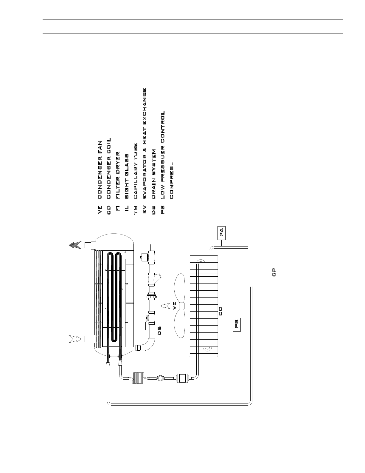
Schematic Flow Diagram11
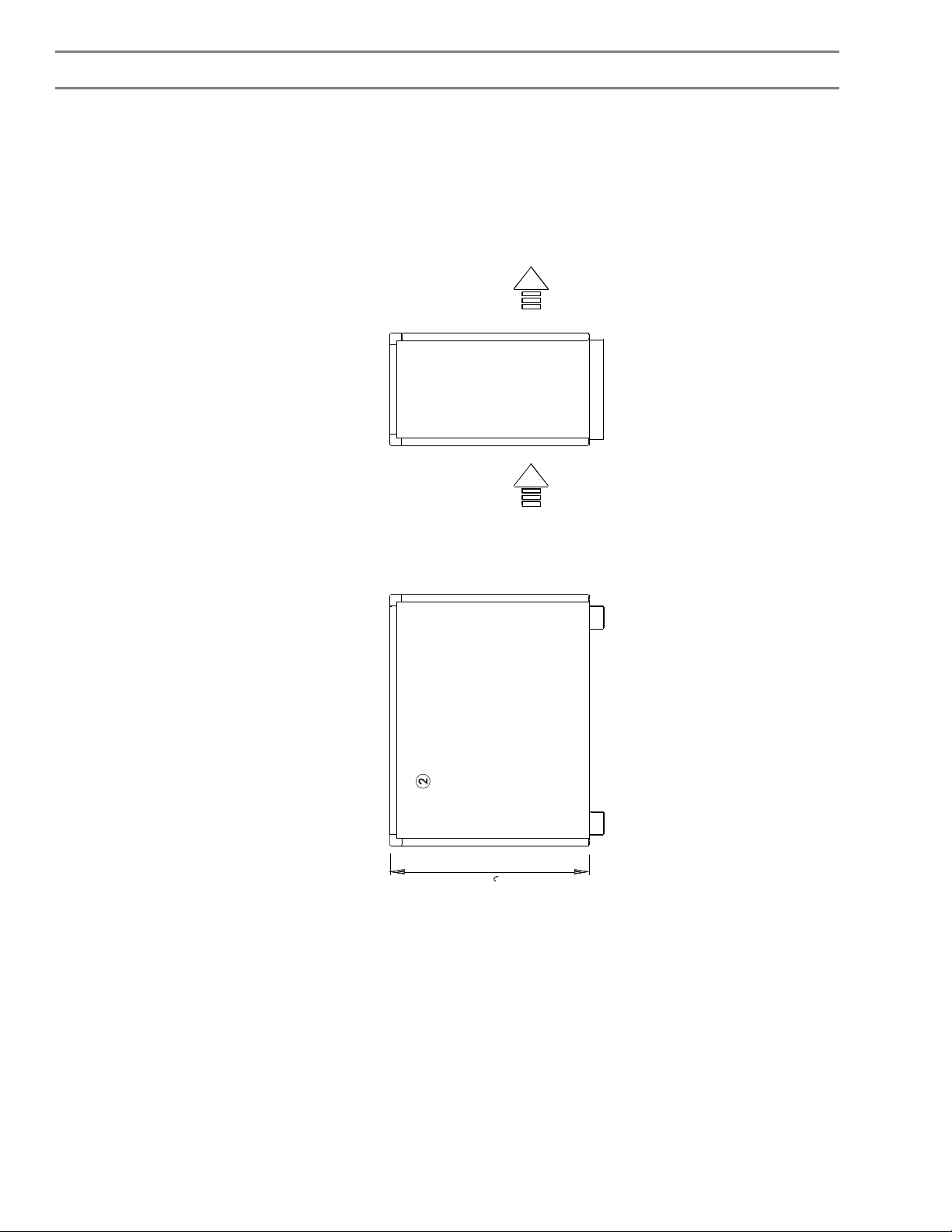
General Arrangement Drawings12
Technical Description of Components17
Technical Data Tables18
Electrical Description20
Wiring Diagrams22
Control of Refrigerant Discharge26
Log Book26
Routine Maintenance27
Fault Finding28
Notes31
Information
This product has been manufactured for: Denco Limited
Dolphin House
Moreton Business Park
Moreton-on-Lugg
Hereford
HR4 8DS
Telephone: +44 (0) 1432 277277
Facsimile: +44 (0) 1432 377364
Page 3

Important
The refrigerant available on the C series of Compressed Air Dryers is Refrigerant R134a or Refrigerant
R407C. It is imperative that refrigerants are not mixed. A label is fixed to each compressor, which identifies the
refrigerant being used within the unit, and that refrigerant ONLY should be used in the dryer. R134a & R407C
are ozone benign refrigerants and meet the requirements of the revised “Montreal Protocol”. These refrigerants
require the use of ESTER oil within the system and not MINERAL oil as used with R22 systems, and therefore
again these oils must NOT be mixed.
Introduction
The Denco C series of Compressed Air Dryers are used to remove entrained moisture from compressed air
supply systems and thus protect the various components and are designed such that routine maintenance is
kept to a minimum.
Most parts are field replaceable but should major maintenance or repair be required please refer to Denco
Limited or an authorised distributor.
NOTE: This manual applies ONLY to the C series of Compressed Air Dryers. For actual model refer to serial
plate fitted to the unit. For other ranges refer to the respective manuals.
Warning
These Dryers are only designed for use with compressed air at or below the design maximum pressure (see
Technical Data sheet(s) for maximum working pressures applicable). These Dryers must NOT be used for drying
any other gases or fluids at other pressures. Operation of these Dryers using compressed air of a greater
temperature than that specified will cause excessively high pressures in the refrigeration system, which may be
dangerous.
The air supplied to the dryer must be free of any corrosive or combustible gases or impurities.
Warranty
The warranty will only be considered valid if the equipment supplied is installed, commissioned and maintained
in accordance with the instructions issued by Denco Limited. Furthermore the Company will not accept any
liability whatsoever should the Dryer be installed incorrectly or operated outside its stated design duties and
operating conditions or improper use be made of the equipment.
Page 4

Health and Safety
Due regard shall be given to observing safe procedures when working with or on the equipment. It is the
responsibility of the Installer / Operator / Customer to ensure that the “Health and Safety at Work Act (1974)”
and Normal Safe Working Procedures are adhered to at all times.
With reference to the "Control of Substances Hazardous to Health Regulations 1988 (COSHH)” the following
paragraphs have been extracted from Denco’s letter responding to information requested
“However, certain substances contained within materials used in the manufacture of our units could be
hazardous when released, if the unit is misused, abused or maintained by unskilled labour.
Fumes would be released if pipework or slab foam insulation (Armaflex or similar), electrical insulation or vinyl
coatings were exposed to naked flame. It will be, therefore, that no naked flame should be applied to any of the
above mentioned substances, nor to print, rubber or plastic parts.
Light oil is applied to some bare metal parts as a protective coating and this could cause dermatic reaction to
sensitive skin.
Refrigerants contain hydrofluorocarbons (HFC’s). Glycol/water mix is used during manufacture but drained
before delivery. The quantities in use are minimal but care should be taken in disposal.
We trust that this information is sufficient but should you require further information regarding our products or
maintenance service, please contact our sales department.”
Machine Card
In order to comply with BS EN 378-2:2000 “Refrigeration Systems and Heat Pumps – Safety and Environmental
Requirements”, an adequately protected card shall be situated near the operating site and must be clearly
readable. The card shall at least contain the following information:
1) Name, address and telephone number of the installer, his service department, or the person responsible
for the refrigeration and the addresses and telephone numbers of the Fire Department, Police, Hospitals
and Burns Centres
2) The refrigerant is R134a or R407C (refer to Technical Data Table)
3) To shut down the Compressed Air Dryer in an emergency, switch off the unit using the ON/OFF isolating
switch on the front panel. The mains supply to the Dryer should be isolated at the mains isolator.
4) Maximum Allowable Pressures
Compressed Air 13 barg
5) Flammability Limits in Air
NONE
Page 5

General Safety Instructions
IMPORTANT:THE FOLLOWING SAFETY PRECAUTIONS MUST BE READ AND UNDERSTOOD BEFORE
REPAIR OR MAINTENANCE WORK IS ATTEMPTED.
General
Beware of the following danger areas within the dryer :
a) Any rotating components (fan etc.)
b) Sharp edges (coil fins, etc.)
c) Hot refrigeration pipework
d) Possible live electrical components or terminals
The refrigeration and compressed air circuits can operate at high pressures and unauthorised tampering
may cause injury or damage.
Discharge from the condensate drain will contain oil, and therefore should be disposed of safely.
Do not place either temporary or permanent loads on or against the unit.
Mechanical
The dryer shall be fully disconnected or isolated from the compressed air supply and any remaining pressure
released safely.
The refrigeration circuit shall be fully emptied of gas safely BEFORE work is attempted on any associated
components. Refrigerant gas may be toxic and/or harmful (burns - both hot and cold), therefore use the
necessary protective equipment (such as goggles and gloves) at all times when emptying the system,
If any heat or flame is to be used on or near the unit care shall be taken to avoid contact with combustible
surfaces. Furthermore, it should be noted that the insulation materials and refrigerant might give off toxic
fumes when heated. Whenever heat or flame is used the working area shall be thoroughly ventilated
BEFORE and DURING this operation. Proper fire precautions shall be observed and the necessary fire
safety equipment on hand, typical for electrical, oil and foam fires,
The refrigerant used is refrigerant R134a or R407C. No other type of refrigerant or mixture shall be used.
If recharging or adding refrigerant to the unit ensure correct refrigerant and oil are used, check labels on
compressor identifying refrigerant being used.
Ester oils used in systems with R134a & R407C are very hygroscopic (adsorb moisture very quickly),
therefore care should be taken to ensure that the systems and any ester oil containers are not left open to
atmosphere for any length of time.
If any oil is removed from the system it shall be disposed of safely. Do not re-use or use for any other
purpose.
When working on the dryers beware of any rotating components and any hot refrigerant pipework.
Observe any safety labels fitted to various parts of the dryer.
Electrical
The dryers are designed to operate only on a 220/240 volt, 1 phase, 50-60 Hz live neutral and earth supply.
THE EARTH CONNECTION MUST NEVER BE OMITTED. The voltage tolerance for each model is shown
on the respective wiring diagram in this Manual.
The dryer must be fully isolated from the supply BEFORE maintenance work is started.
The dryer MUST NOT be used on other supplies without prior approval from the manufacturer.
The dryer should only be used in a SAFE (i.e. non- hazardous) area.
Observe any electrical safety labels fitted to various parts of the dryer.
Solenoid coils should not be removed from valve stem until they have been electrically disconnected.
Page 6
Refrigerant Safety Data
Reactivity Data
UnstableStability
StableYES
Incompatibility (Materials and Conditions to Avoid)
May react violently with sodium, potassium, barium or other alkali or alkaline earth materials.
Magnesium and alloys containing more than 2% magnesium. All finely divided metals.
Hazardous Decomposition Products
Halogen acids formed by thermal decomposition.
Fire and Explosion Hazard Data
Flash Point (oC) Method
-----Flammable Limits (% by Vol. in Air) Lower Upper
Non Flammable --- --Would any material saturated Materials:
with this product be subject to
spontaneous combustion? No
Fire Extinguishing Data
Non flammable, not combustible.
Special Fire Fighting Procedures
Fire exposed containers should be kept cool with water sprays.
Usual Fire and Explosion Hazards
Will decompose in contact with high temperature sources, i.e. flames, electric arcs, etc. to produce irritating
and highly toxic acidic products. Breathing apparatus should be worn if refrigerant is exposed to fire
conditions. Containers may burst if overheated.
Conditions to Avoid
Use in presence of naked flames, red-hot surfaces. High moisture levels
Auto-ignition Temperature (oC)
---
Precautions in Handling and Use
General Precautions
Atmospheric levels should be minimised and kept as low as reasonably practicable below hygiene standard.
Avoid inhalation of high concentrations of vapour. Heavy vapour collects at low levels. Ventilate by extraction
at lowest level. Decomposes in flames, arcs and at red heat to toxic acid by-products. Avoid contact between
liquid and skin or eyes.
Ventilation Requirements
Ventilation may be required to achieve a sufficiently
low exposure level. Extract at lowest level. Vapour
collects in pits, trenches, basements, sewers and in
confined spaces and vessels.
Protective Clothes
Where liquid splash is a possibility gloves suitable
for use in low temperatures should be worn e.g.
chlorobutyl rubber with cotton liners.
Overalls.
Storage
Containers should be stored in a cool dry place away from fire risk and sources of heat. They should not be
exposed to direct radiation from sources of heat such as steam or electric radiators. Do not heat containers
beyond 45oC.
Respiratory Protection
Where doubt exists on atmospheric concentration and
particularly in confined spaces, self-contained
breathing apparatus should be considered. Breathing
apparatus should always be worn in a fire situation.
Eye Protection
Goggles.
Page 7
Health Hazard Data and First Aid
Short term effects of over exposure when:
In contact with skin: Liquid splashes may cause freeze burns. No information found on irritancy or
sensitisation. There is no known hazard due to absorption through the skin.
In contact with eyes: Liquid splashes or vapour spray may result in freezing of tissue or eye fluids.
Inhaled: Very high concentrations may produce anaesthetic effects and can act as an
asphyxiant by limiting available oxygen. They also may prove suddenly fatal
(cardiac sensitisation).
10 mineffective concentration 50 28% (Rat)
15 min lethal concentration 50 > 80% (Rat)
4 hr lethal concentration 50 > 50% (Rat)
Threshold for cardiac sensitisation 7.5% 5 min (Dog)
Ingested: Extremely unlikely to occur under normal industrial use.
Should this occur freeze burns will result.
Long term effects of over exposure:
No effects have been seen in rats exposed to up to 50,000 ppm for 90 days. It is not teratogenic in rats or
rabbits. Short-term screening tests for carcinogenicity have proved negative. No long-term effects were noted
when administered by gavage to rats at a dose of 300 mg/kg/day for one year and the rats held for the
remainder of their life span.
Occupational Exposure Limit (OEL):
1000 ppm v/v – 8 hr TWA value.
Emergency and First Aid Procedures:
Skin: Thaw affected areas with water, remove contaminated clothing carefully, wash affected areas
of skin thoroughly with copious amounts of warm water. If symptoms occur, obtain medical
attention.
Eyes: Irrigate with eyewash solution or clean water for at least 10 minutes. Obtain immediate
medical attention.
Inhalation: Remove patient to fresh air, keep warm and at rest, administer oxygen if necessary. Apply
artificial respiration if breathing has ceased. Apply external cardiac massage in the event of
cardiac arrest. The use of adrenaline or similar sympathomimetic drug should be
avoided. Obtain immediate medical attention.
Ingestion: Highly unlikely. Should this occur freeze burns will result.
Further Medical Advice
Symptomatic and supportive therapy as indicated. Cardiac sensitisation has been described which may, in
the presence of circulating catecholamines such as adrenaline, give rise to cardiac arrythmias and
subsequent arrest following exposure to high concentrations of vapour. Therefore, adrenaline and similar
sympathomimetic drugs should be avoided.
Spill or Leak Procedures
Steps to be taken in event of Spill or Release
Shut off leak if without risk. Allow spilled liquid to evaporate. Contain spillage with sand or earth, prevent
liquid entering sewers, basements and pits since vapour may create suffocating atmosphere.
Neutralising Chemicals
None necessary.
Disposal Procedures
Best to recover and recycle. If this is not possible, destruction is to be in an approved facility, which is
equipped to absorb and neutralise acids and other toxic processing products.
Page 8

Installation - General
Storage
The equipment should be stored in a secure frost free area with a maximum ambient of 55°C and maximum
humidity of 90% non-condensing.
Unpacking
Carefully remove the unit from its packing and examine it for obvious defects or damage including:
Paint damage.
Case deformation.
Integrity of electrical cable.
Breakage of gauge glass (where applicable).
If any of the above faults are noted, or any other defect or damage is observed and it becomes necessary to
return the unit for rectification, this should be done in accordance with the procedure agreed with the supplier.
Moving
Due care shall be taken when moving the dryer not to cause injury to personnel through improper safety
precautions.
NOTE: The dryer must be kept in the upright position at all times to avoid damaging the compressor.
Lifting
The units are designed for fork lifting from the base. The base is uneven – ensure that the forks are extended
fully through.
Do NOT use convenient pipes, bolts or apertures in the dryer as lifting points.
Position of Unit
The dryer should be placed on a firm, level load bearing surface of adequate strength and a suitable area be left
clear of obstruction at the inlet and outlet grilles and the access panels (see note reference ambient
temperatures). To prevent air recirculation the condenser coil must be situated at least 500 mm from a wall,
partition etc. Sufficient space must be left for service access around the unit.
The C series unit are NOT suitable for direct wall mounting.
Ambient Temperatures
Care should be taken to ensure that there is adequate air circulation and the Dryers should not be placed in
areas where the ambient temperature is likely to exceed the recommended design maximum (refer to Technical
Data tables).
Removal of Covers
General access for installation or maintenance is via the covers which are removable by removing the screws
around the panels.
Corrosion
Air cooled units are designed for operation in normal ambient air. Any corrosive agent in the air such as
ammonia, sea water spray etc. will cause corrosion and would require special protective measures. Corrosion
can result in release of pressure and refrigerant.
Page 9
Installation - Electrical
The C series Dryers require a 220/240 Volt 1 phase and neutral 50-60 Hz supply. A flying lead is installed on the
dryer for convenience. The cable core colours are:
BrownLive
BlueNeutral
Green / YellowEarth
If the unit is connected to a junction box, receiving its supply from another source (e.g., auxiliary contacts of a
main starter, or a relay), then it is important that electrical protection is provided by means of a suitably rated
H.R.C. fuse located in the line. Installation must comply with the latest edition of IEE Wiring Regulations, Safety
Standards and any Local Codes of Practice that apply.
Installation - Mechanical
Connect the compressed air pipework to the Dryer using approved pipe and fittings of the correct rating and
type. To ensure damage does not occur to internal pipework and components during the connection process,
remove access cover(s) and if necessary support the internal pipework / components. Please ensure that ALL
shut off valves are fully open before starting unit.
The drain connection should be connected to a suitably sized drain line and piped to a suitable oil / water
separator prior to drain.
Installation Recommendations
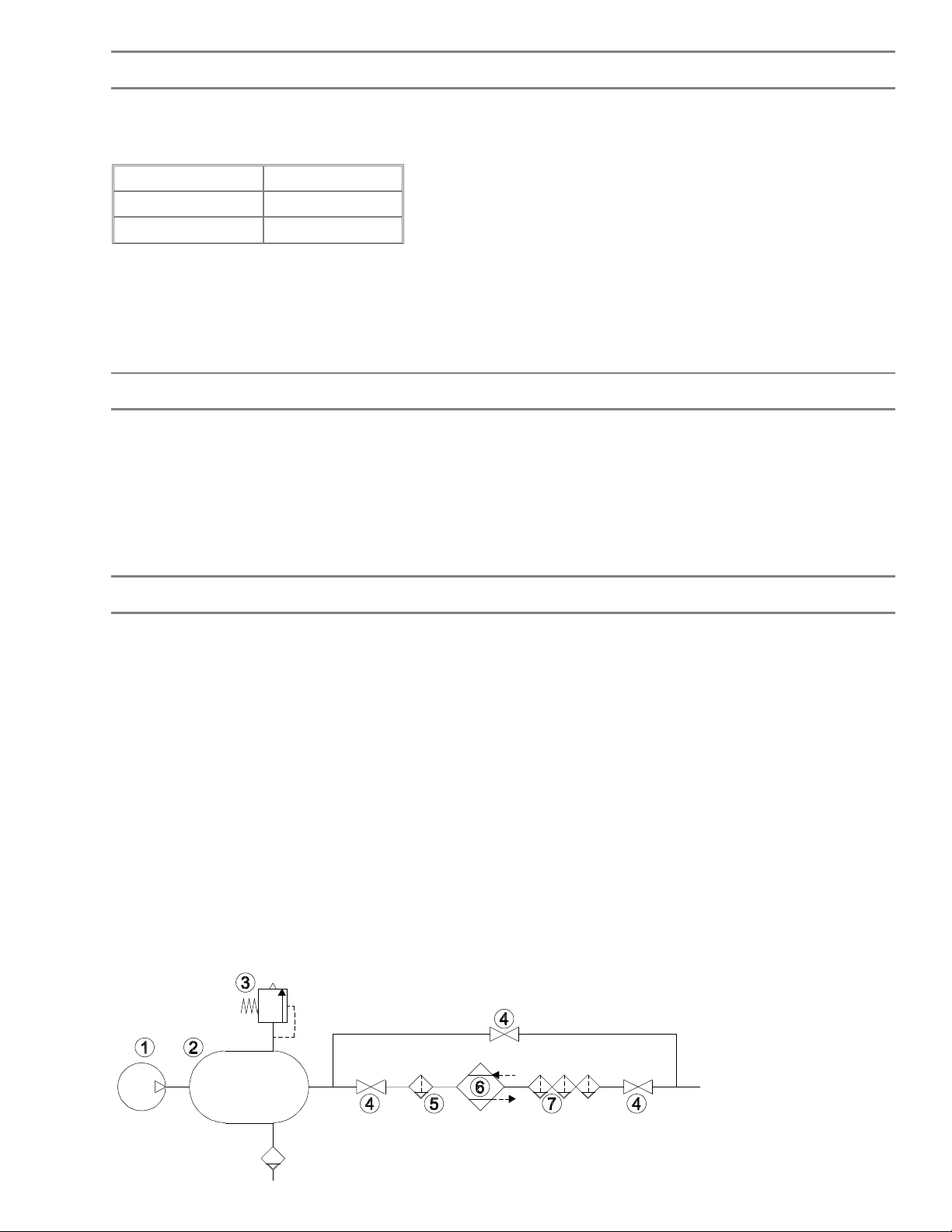
The compressed air pipework should incorporate sufficient shut-off valves to enable the dryer to be by-passed
and/or disconnected in the event of repair or replacement.
A purge valve should also be fitted at a convenient point to enable the air pressure to be released safely and
gradually before undoing any connections.
A suitably sized pressure safety device should be fitted to prevent over-pressurisation of the compressed air
dryer.
If the compressor pumps intermittently, or the total air demand does not exceed the total flow rate of the
compressor, the dryer MUST be installed downstream of the receiver.
If the receiver is sized to permit wide fluctuations on air demand or if peak demand exceed compressor
maximum flow rate, the dryer SHOULD be installed upstream of the receiver.
A minimum of 5 micron (Denco recommend 1 micron) pre-filter must be fitted to remove impurities from the air
prior to it entering the dryer. Additional filtration may be required downstream of the dryer subject to the site
requirements.
1 Air Compressor
2 Receiver
3 Safety Valve
4 Shut off valve
5 Pre-filter (1 micron)
6 Refrigerant Dryer
7 After-filter
(0.01 micron, dust filter &
activated carbon as required)
Page 10
Commissioning
The units are factory pre-set and commissioned and should not need any field adjustment. However, if after a
period of time the unit is found to be operating poorly or incorrectly, this may be due to a range of faults or
problems which may be analysed by reference to the Fault Finding section of this manual.
Start-up Procedure
Important
Do not allow the compressed air to flow through the unit until the following checks have been made
AND THE UNIT SWITCHED ON.
1. Switch the on-off switch / isolator to the "ON" (I) position. The following observations will indicate correct
operation:
The fan will start
An airflow will be felt from the condenser discharge grille
After 2 minutes, the compressor will start and a low-level noise will be heard similar to that of a
domestic refrigerator.
2. After a further 5 minutes, slowly allow the compressed air supply into the dryer.
3. Press the VALVE button to check the operation of the condensate discharge valve.
Note:
Some safety cut outs are auto reset, and unless isolated from the mains the unit can be re-started without
warning.
Pressure switches should be adjusted with the power off.
Any work done to the Compressed Air Dryer involving entry into the control panel, fitting gauges, adjusting
controls, charging the system, evacuating the system or opening the system in any way, must be carried out
by a FULLY QUALIFIED REFRIGERATION ENGINEER. A City and Guilds 2078 or equivalent certificate is
strongly advised and will soon be mandatory.
Description of Operation
The saturated compressed air enters the evaporator and is pre-cooled by the outgoing cooler air. The internal
refrigerant circuit is then used to further cool the air to its required dewpoint. Once dewpoint is achieved, the
moisture condenses, and the water droplets are ejected via the condensate drain system. The cold, dry air is
then warmed by the incoming warm air and discharged, dry, to the downstream pipework.
The refrigerant circuit is of conventional design operating on ozone benign Refrigerant R134a of R407c and
incorporates an hermetic compressor, combined air/air and evaporator type heat exchanger, an air cooled
condenser, an expansion device (capillary tube or thermostatic expansion valve), a filter/dryer, a hot gas bypass valve. The refrigeration circuit is controlled by means of a simple but effective panel mounted controller
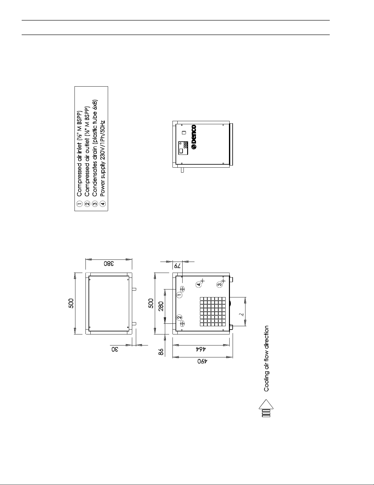
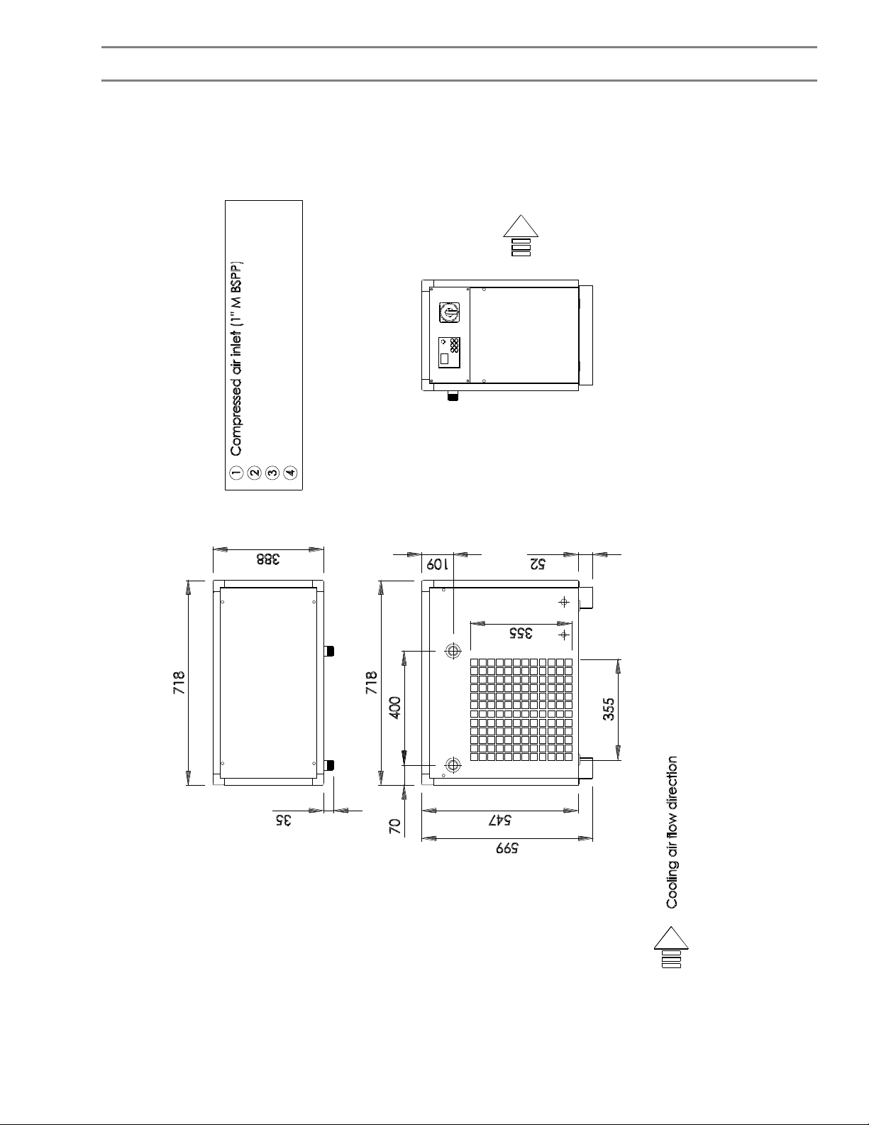
Schematic Flow and General Arrangement Drawings
Model NumbersSchematic Flow
Diagram Number
C9-1, C14-1, C19-1PS1061-C-021PS1061-C-001
C31-2, C39-2, C58-2PS1061-C-021PS1061-C-002
C92-3, C120-3PS1061-C-021PS1061-C-003
C147-3PS1061-C-021PS1061-C-004
C175-4, C238-4PS1061-C-021PS1061-C-005
Outline Arrangement
Drawing Number
Page 11
PS1061-C-021
Page 12
PS1061-C-001
Page 13
PS1061-C-002
Page 14
PS1061-C-003
Page 15
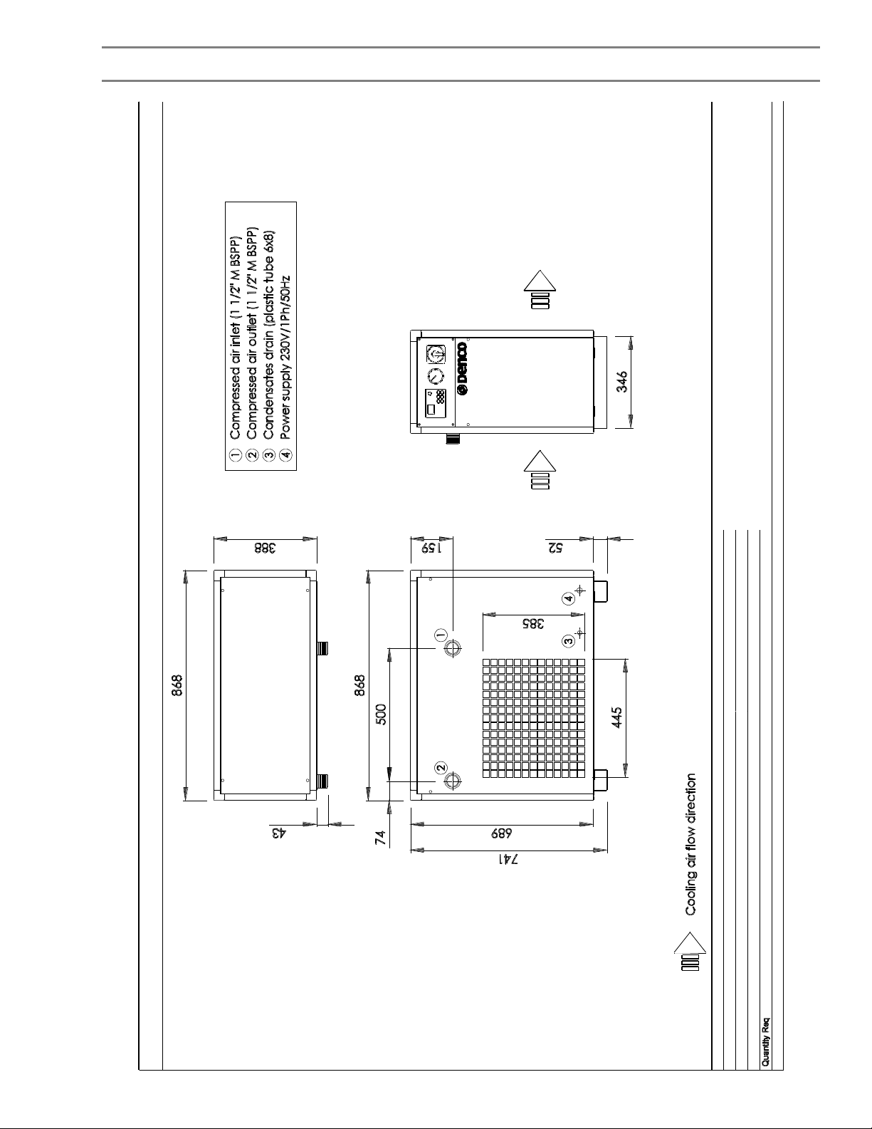
PS1061-C-004
Page 16
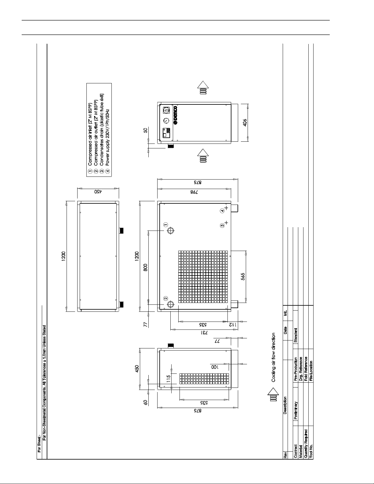
PS1061-C-005
Page 17

Technical Description of Components
1. Compressor
This is a fully hermetic, high back pressure single phase type; the internal components being mounted on
springs to minimise vibration.
2. Heat Exchanger
The heat exchanger is coil / tube design and incorporates an air / air and refrigerant / air heat exchanger with an
integral moisture separator
3. Air Cooled Condenser
A fan assisted air cooled condenser is used to remove the remaining heat from the refrigerant. Air movement is
achieved by a multi-bladed propeller type fan directly driven by a single phase motor.
4. Hot Gas By-pass Valve
This valve is installed such that discharge gas may be diverted to the suction line when the suction temperature
starts to fall below a preset level. This level is set such that the moisture removed from the system cannot
freeze in the evaporator.
5. Controller
A digital readout temperature controller is fitted to allow the operating condition of the dryer to be monitored and
drain valve settings to be adjusted.
6. Casing
The unit is housed in coated sheet steel casing. Removable covers are fitted where necessary to provide
access for service or repair.
Page 18
Technical Data Table
ModelC9-1C14-1C19-1C31-2C39-2C58-2
Nominal Airflow
Nominal Pressure Dropbar0.30.30.30.30.30.3
Maximum Working Pressurebar131313131313
Maximum Operating Ambient°C434343434343
Maximum Standing Ambient°C535353535353
Minimum Ambient°C555555
Widthmm380380380388388388
Depthmm500500500718718718
Heightmm490490490600600600
Air ConnectionsBSP½½½111
Drain Connectionsmm od888888
Electrical Supply
Installed PowerkW0.450.570.660.960.960.85
Full Load CurrentAmps22.634.354.353.9
Refrigerant-R134aR407C
Refrigerant Chargekgs0.350.350.550.80.81.3
†
§
m3/min0.580.831.161.832.333.5
-220-240 volt / 1 phase / 50-60 Hz
Notes:
†
Nominal airflow in m3/min FAD at 20°C, working pressure 7.0 bar gauge with an inlet temperature of 35°C in an
ambient of 25°C. Please note: applying the Dryer for higher than standard ambient and / or air inlet temperature
will derate the performance.
‡
Pressure switches are factory set and must ON NO ACCOUNT be altered from the above settings.
§
For voltage tolerance refer to respective schematic wiring diagram.
Page 19
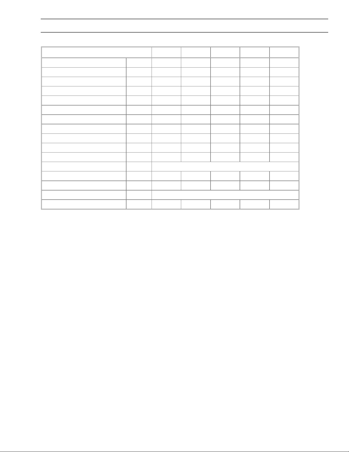
Technical Data Table
ModelC92-3C120-3C147-3C175-4C238-4
Nominal Airflow
Nominal Pressure Dropbar0.30.30.30.30.3
Maximum Working Pressurebar1313131313
Maximum Operating Ambient°C4343434343
Maximum Standing Ambient°C5353535353
Minimum Ambient°C55555
Widthmm388388388388388
Depthmm86886886811481148
Heightmm740740740875875
Air ConnectionsBSP1½1½1½22
Drain Connectionsmm od88888
Electrical Supply
Installed PowerkW1.491.732.012.322.76
Full Load CurrentAmps6.767.869.1610.5612.56
Refrigerant-R407C
Refrigerant Chargekgs1.81.8222.5
†
§
m3/min5.57.168.8310.514.33
-220-240 volt / 1 phase / 50-60 Hz
Notes:
†
Nominal airflow in m3/min FAD at 20°C, working pressure 7.0 bar gauge with an inlet temperature of 35°C in an
ambient of 25°C. Please note: applying the Dryer for higher than standard ambient and / or air inlet temperature
will derate the performance.
‡
Pressure switches are factory set and must ON NO ACCOUNT be altered from the above settings.
§
For voltage tolerance refer to respective schematic wiring diagram.
Page 20
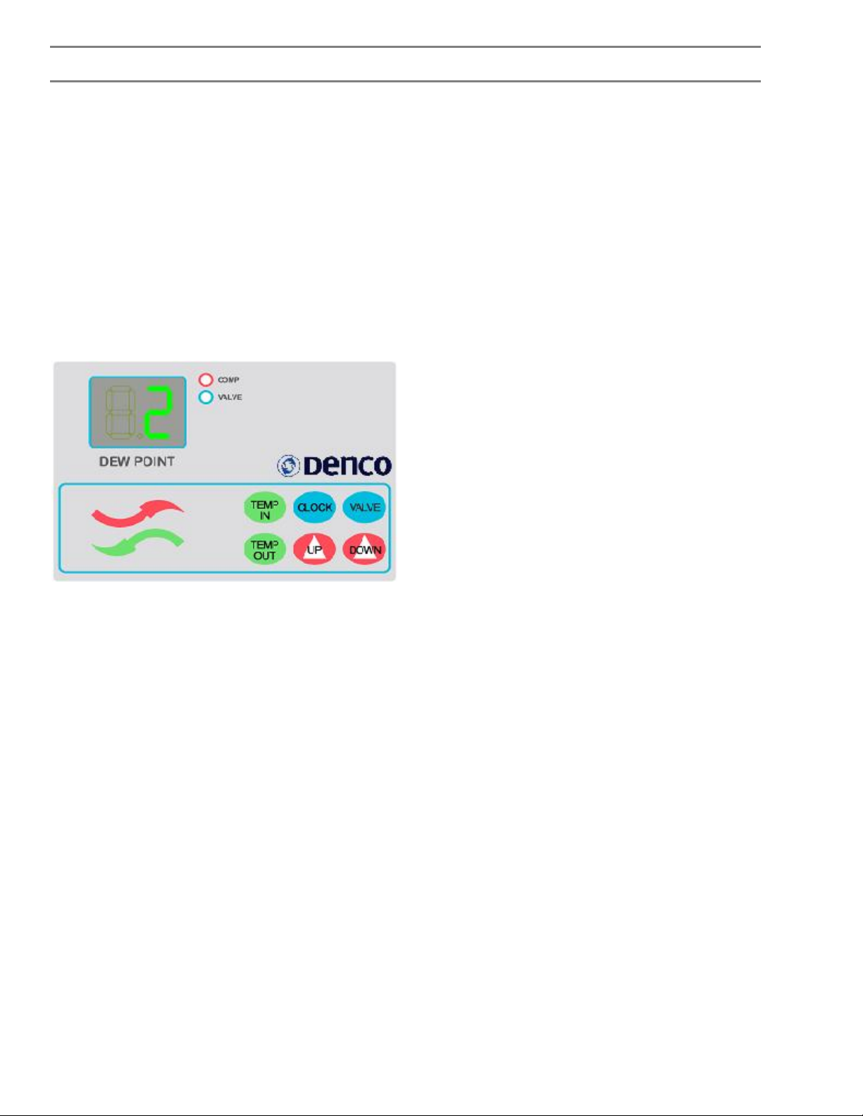
Electrical Description
Description of Components
1."ON / OFF" Switch
This switches the live side of the power supply to the circuit. All models are fitted with a rotary type cam switch.
2.Compressor (complete with control box)
The compressor is a single phase type and incorporates a "start" circuit to avoid risk of a stalled motor on startup.
3.General
The air cooled condenser fan will run under the control of the controller sensing the temperature in the
compressor discharge line.
Controller
The above controller is fitted on the C series of compressed air dryers. It is used to control the fan and the hot
gas valve (if fitted). It also displays the dewpoint temperature and controls the time settings for the drain valve.
This time setting can be changed to suit the site requirements as follows.
Note: the “TEMP IN” and “TEMP OUT” buttons are not functional on the C series compressed air dryers
1. Valve Close Time (the time the valve is closed between discharges. Variable between 1 & 20 mins)
Hold the “UP” button for 15 seconds. The display will start blinking, displaying the valve close time. Press the
“UP” or “DOWN” arrows while the display is blinking to change the setting. If any other button is pressed, the
display will return to original display and ignore the new setting. After the new value has been set, leave the
controller for 15 seconds. The display will return to the dewpoint value, and the new setting will be stored.
2. Valve Open Time (the time the valve is open to discharge. Variable between 4 & 20 secs)
Hold the “CLOCK” button for 15 seconds. The display will start blinking, displaying the valve open time. Press
the “UP” or “DOWN” arrows while the display is blinking to change the setting. If any other button is pressed, the
display will return to original display and ignore the new setting. After the new value has been set, leave the
controller for 15 seconds. The display will return to the dewpoint value, and the new setting will be stored.
Page 21

Wiring Diagrams
To assist understanding of the electrical circuitry the following wiring diagrams are included:
Model NumbersSchematic Wiring
Diagram Number
C9-1, C14-1, C19-1PS1061-C-011
C31-2, C39-2, C58-2PS1061-C-012
C92-3, C120-3, C147-3PS1061-C-013
C175-4, C238-4PS1061-C-014
Page 22
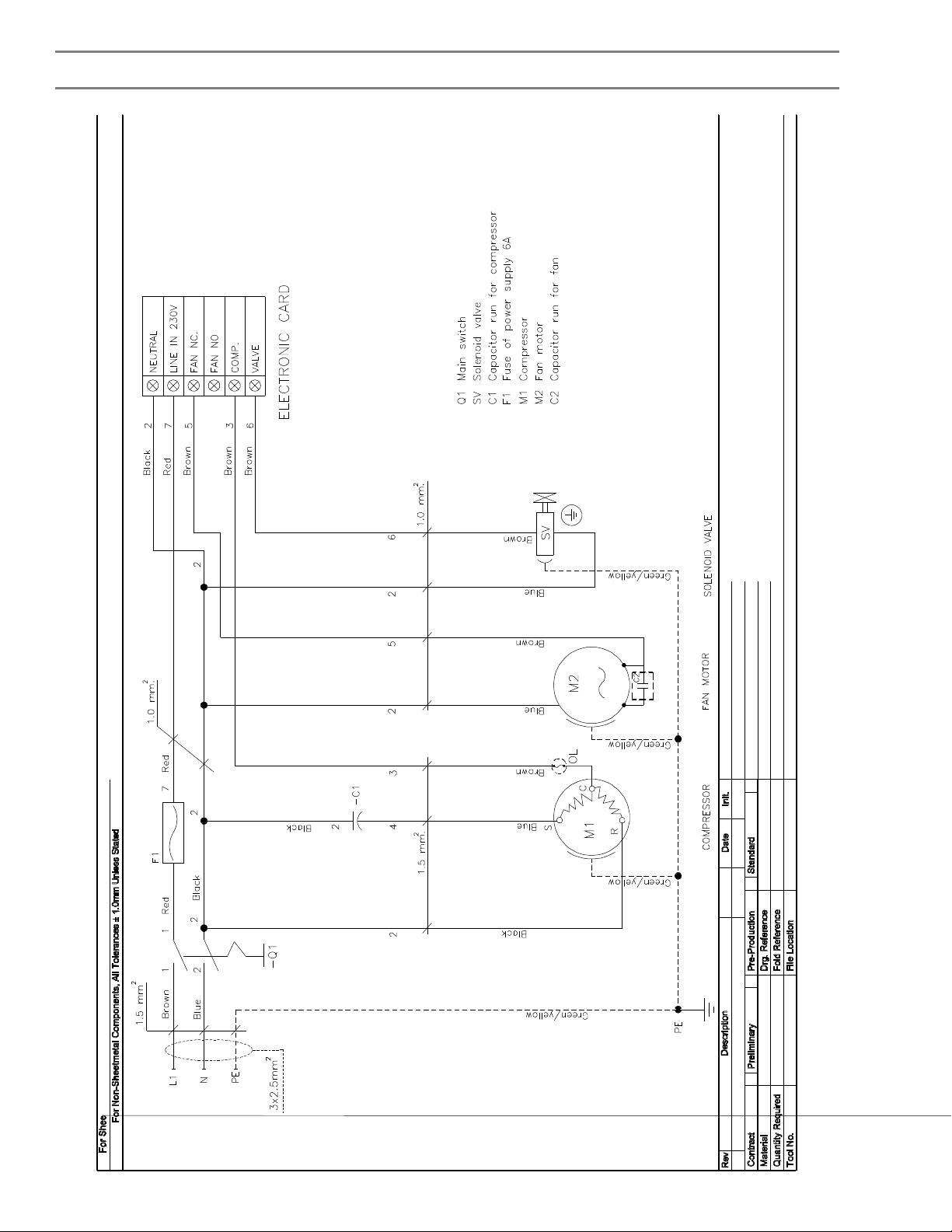
PS1061-C-011
Page 23
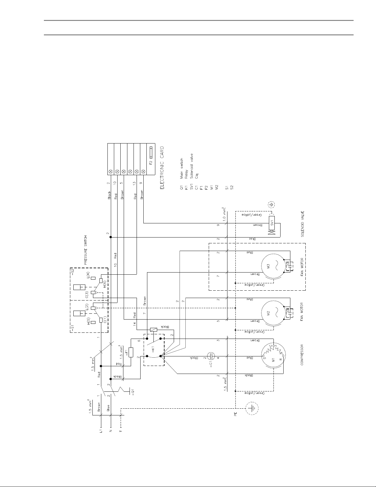
PS1061-C-012
Page 24
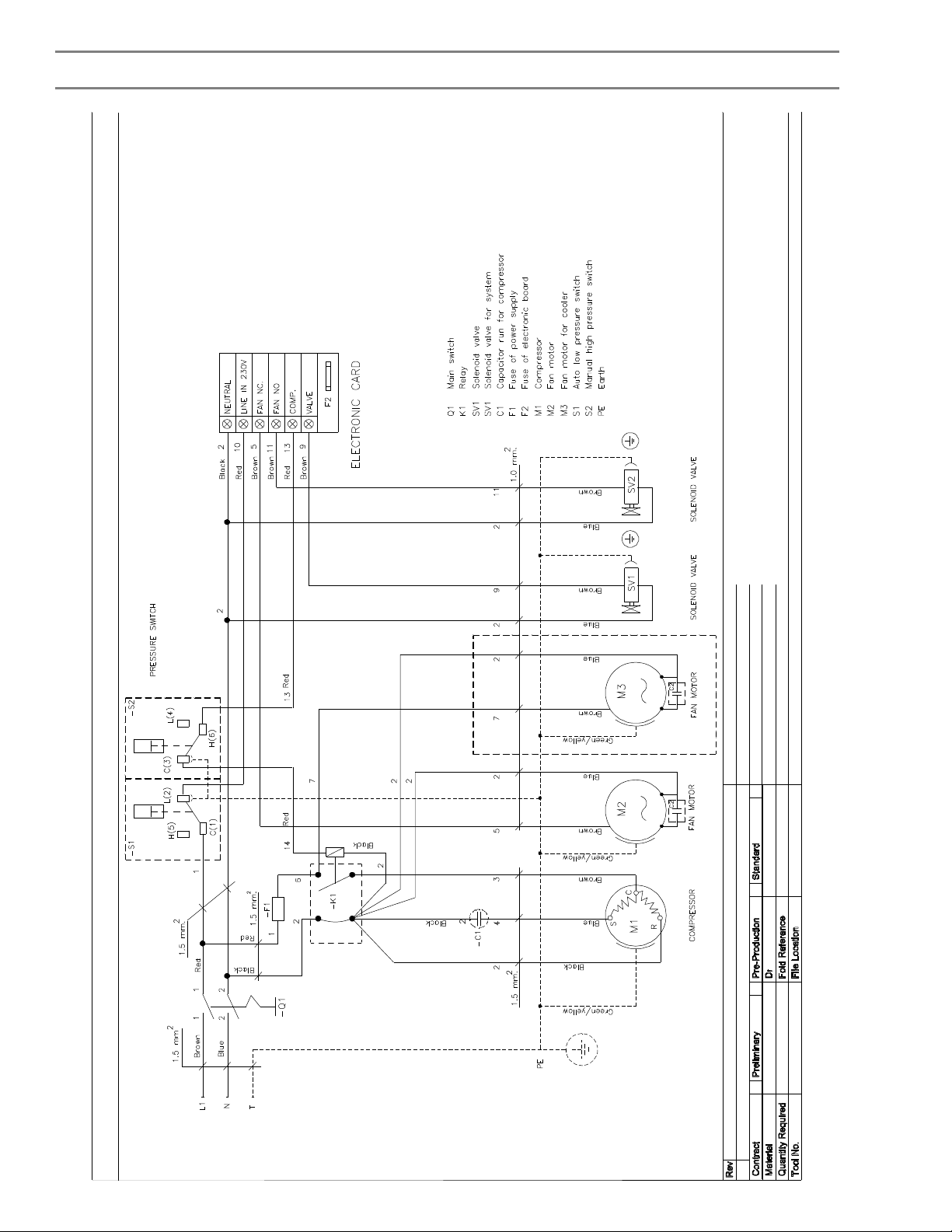
PS1061-C-013
Page 25
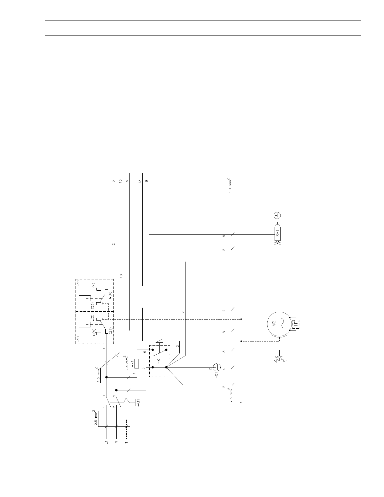
PS1061-C-014
Page 26

Control of Refrigerant Discharge
By international agreement, the worldwide use of certain refrigerants will be reduced in stages. To this end,
listed below are suggestions on how refrigeration engineers can contribute by the discontinuing of releasing any
refrigerant gas to the atmosphere. Release of refrigerant to the atmosphere is an offence under Section 33
of the Environmental Protection Act 1990.
DO NOT . . .DO . . .
(1) Blow off refrigerants to atmosphere.(1) Pump down into a receiver or empty cylinder using
Reclaim Equipment.
(2) Use refrigerants to clean coils etc.(2) Clean coils etc. using a hand brush, vacuum or
compressed air.
(3) Leak test using pure refrigerant.(3) Leak test using Nitrogen and just a trace of refrigerant
gas.
(4) Recharge before mending leaks.(4) Find and mend leaks before recharging system.
(5) Dispose refrigerant gas to waste.(5) Send used refrigerant gas back for reprocessing.
Note: Disposal of refrigerants must be closely controlled. To dispose of refrigerant or a refrigerant
system an approved agent must be used. If you have any doubt contact Denco Limited.
Log Book
In order to comply with BS EN 378, the user should keep an updated log book of the Compressed Air Dryer.
The log book should record:(a) The details of all maintenance and repair work.
(b) The quantities of new, re-used, or recycled refrigerant which have been charged on each occasion, and the
quantities of refrigerant which have been transferred.
(c) Any analysis of re-used refrigerant.
(d) The source of re-used refrigerant.
(e) Changes and replacements of components of the system.
(f) The results of all periodic routine tests.
(g) Significant periods of non-use.
The log book should be kept in the machinery room or stored in a computer system. It must be accessible to the
competent person when servicing or testing.
Page 27

Routine Maintenance
It is not normally necessary to open the refrigerant circuit. If a problem is suspected it is strongly recommended
that unit maintenance or repair is undertaken by a CITY & GUILDS 2078 (or equivalent) COMPETENT
REFRIGERATION ENGINEER. A City and Guilds 2078 (or equivalent) certificate will soon be mandatory.
Daily
Check that the "ON / OFF" switch/isolator is in the "ON" or " I " position.
Check condenser fan for airflow.
Weekly
Check condensate drain operation.
Monthly
Check condenser fins and grilles for cleanliness or damage. Repair as necessary.
Check condenser fan blades for damage.
Quarterly
Check tightness of electrical connections.
Check all wiring for damage to insulation.
Check running current.
Clean condensate line strainer.
Bi-annually
Check operation of refrigerant circuit (including temperatures and pressures)
Check the pipework connections for
Annually
Thoroughly clean unit including condenser fins.
Check internal pipework and components for signs of wear or damage.
Note:
Some safety cut outs are auto reset, and unless isolated from the mains the unit can be re-started without
warning.
Pressure switches should be adjusted with the power off.
Any work done to the Compressed Air Dryer involving entry into the control panel, fitting gauges, adjusting
controls, charging the system, evacuating the system or opening the system in any way, must be carried out
by a FULLY QUALIFIED REFRIGERATION ENGINEER.
Page 28

Fault Finding
The following fault finding chart relates various symptoms and faults of the refrigeration system.
Before attempting to identify a refrigeration system fault it must first be established that the DESIGN
CONDITIONS to the compressed air system are being met i.e. flow, pressure and temperature.
Excessive overload will be caused by:
1. Excessive compressed air inlet temperature.
2. Compressed air pressure too low.
3. Compressed air flow in excess of design.
4. High ambient air temperature.
Dirt, scale and/or excessive oil in the compressed air may cause one or more of the following:
Drain blockage leading to moisture being carried over into the compressed air system.
Excessive pressure drop in compressed air circuit.
Excessive fouling of the heat exchanger internal surfaces.
PROBLEMCAUSESYMPTOMREMEDY
A
Dew point
too high
Compressed air temperature
too high.
Compressed air flow rate too
high.
Compressed air pressure too
low.
Ambient temperature too high.The digital display panel
Dirty fins of the condenser.The digital display panel
Condensing unit clogged.The digital display panel
The fan runs backwards (threephase)
Refrigerant gas leakThe compressor top is very
The HP Pressure switch has
tripped
The digital display panel
indicates
a value > 4C° permanently
The digital display panel
indicates
a value > 4C° permanently
The digital display panel
indicates
a value > 4C° permanently
indicates
a value > 4C° permanently
indicates
a value > 4C° permanently
indicates
a value > 4C° permanently
The digital display panel
indicates
a value > 4C° permanently
hot;
Low pressure
The digital display panel is
OFF
Return the air inlet
temperature to within the
limits.
Correct the air flow rate
to within the limits of the
dryer.
Correct the pressure to
within the limits.
Correct the temperature
to within the limits.
Clean the condensing
unit fins.
Clean the condensing
unit face.
Correct electrical
connection (phase
inversion)
Find the leak and repair
it.
See note E.
Page 29

Fault Finding continued
PROBLEMCAUSESYMPTOMREMEDY
B
Excessive
drop in
compressed
air pressure.
C
Compressed
air does not
flow through
the dryer.
D
There’s liquid
at air dryer
outlet side
Compressed air flow rate too
high.
Condensate is Frozen. Pressure downstream from
Exchanger Tubes soiled by
impurities in the compressed
air.
The condensate has frozen
and blocked the passage as
the probe is incorrectly
positioned.
The condensate has frozen
and blocked the passage as
the set point is programmed
too low.
The condensate has frozen
and blocked the passage as
the electronic controller has
failed.
Solenoid valve doesn’t work There’s no water or air to
The draining system was
clogged
The working period of solenoid
valve is not long enough
Solenoid valve was clogged There’s no water or air to
Relay on electronics control
board is not working.
The tube system is in cold air
which the temperature is lower
than refined temperature of air
under pressure and the tube is
unprotected, in this case any
liquid will be refined at outside
of tube
Pressure downstream from
the dryer lower than the
expected value.
the dryer lower than the
expected value.
Pressure downstream from
the dryer lower than the
expected value...
Compressed air does not flow
through the dryer.
After starting the compressor,
value 0 is reached in less than
2 minutes.
The compressor stops.
The compressor does not stop
even if the digital display
panel indicates 0 several
minutes.
drain when VALVE button’s
pressed
T strainer was dirty Clean the T strainer
There’s no water or air to
drain when VALVE button’s
pressed
drain when VALVE button’s
pressed
To use volt metre to check
that the relay surface will be
closed to each other or not
when VALVE button‘s
pressed.
No problem with the air dryer
but with the outside
environment
Reduce the compressed
air flow rate.
See note C.
Wash the heat
exchanger tubes with a
non-aggressive detergent
solution. Check the filter
upstream from the dryer.
Position the probe in the
centre of the CDT heat
exchanger.
Increase the set point
value.
Change the electronic
board
Change the solenoid coil
To make the period of
solenoid valve working
longer
To clean solenoid valve
Change the electronics
control board in case
relay is not working.
To protect the tube that
is in low temperature
area.
Page 30

Fault Finding continued
PROBLEMCAUSESYMPTOMREMEDY
E
High
pressure
switch stop
working and
have to
control by
manual
F
Low pressure
Switch stops
working.
G
Prevent
compressor
shut down
Fan motor stop working Every LED at electronics
control board doesn’t light so
its similar to no electric in
circuit
The room temperature is too
high
There’s circulate hot air in the
room causes from wrong
installation
The fins of refine unit were
dirty.
Refine unit was clogged. At The display always show
Room has rather high
temperature and fan has invert
spin.( In case 3 phases used)
The refrigerant leaked. Temperature of the dew point
Air pressure too low, inlet
temperature too high, ambient
temperature too high.
Refrigerant pressure too low,
refrigerant leak
High pressure switch stopped
working
The room temperature is
higher than appropriate
temperature to work.
The room temperature is too
high
At The display always show
>4 °C.
>4 °C.
The cooling air had pass on
fan and refine unit.
too high (Moisture might be
observed near entrance).
The compressor stopped
before reached the fixed
balancing point value.
Compressor restarts again
after 2-3 minutes because the
pressure is back to normal
-Top of the compressor is very
hot
Compressor stops then
restarts after 2~3 seconds.
-Top of the compressor is very
hot
-Compressor stopped working
Repair or change the fan
Adjust temperature in the
room to the appropriate
range or follow by the
manual such as to
increase flow rate air
To change the position of
air dryer to rearrange the
surroundings to limit
circulate air
Clean the refine unit fins
Clean the refine units
Invert the electric phase
Check for leaking marks
Recommend to turn off
the machine.
Check for leaking marks
and refill the refrigerant
Ensure the high
temperature switch is in
good condition; if not
then change a new one.
Page 31

Notes
Page 32
Denco Limited - General Information
working life, together with ease of installation and
The safe choice for all your compressed
air needs
With over 50 years experience in the design and
manufacture of compressed air dryers and associated
industrial plant, Denco has a wide portfolio of products
offering all requisite features and benefits to meet the
ever-increasing demands of international quality and
environmental standards.
Whatever the application, products can be tailored to
exact customer requirements. Consequently, Denco
compressed air equipment can be found in all types
and sizes of industry throughout the World, from small
operator spray booths to major industrial installations.
With an open, flexible approach and a strong focus
on Customer satisfaction, Denco has the skill and
experience to provide the most suitable and cost
effective solution to meet your needs.
Your Denco Distributor is:
The Quality
These units are designed and built using our
unrivalled experience in compressed air drying, with
extensive testing of components and complete
systems. Every aspect is engineered to ensure
maximum reliability, economy of operation and long
maintenance.
Denco Technical Support
Denco’s Technical Support Department offers a
nationwide service network for all users of Denco
equipment.
Users with an existing maintenance contract on the
mainland of Great Britain receive a target response
time of 4 to 6 hours, 24 hours a day, 365 days per
year.
Our Technical Support Engineers operate from
strategically placed service depots supported by
regional stores and a major central stores in Hereford.
To meet the complexity of equipment we train our
engineers in both electrics and microprocessor
controls.
Technical Support contracts are available offering
scheduled preventative maintenance and emergency
call-out nationwide. All schemes are tailored to suit
the customer and site requirements.
Due to our policy of continuous development and improvement, the specifications and data herein are subject to change without notice. We must
therefore reserve the right to supply equipment that may differ from that described and illustrated herein.
All information, including illustrations, contained in this manual, is believed to be accurate and reliable. Users, however, should independently
evaluate the suitability of each product for their own application. Denco makes no warranties as to the accuracy or completeness of the
information, and disclaims any liability regarding its use.
Denco Limited
Head Office
Dolphin House, Moreton Business Park,
Moreton-on-Lugg, Hereford, HR4 8DS, UK.
Telephone: +44 (0) 1432 277277
Fax: +44 (0) 1432 268005
Web: www.denco.co.uk
 Loading...