

Page 1
HP 10 PUMP USER’S MANUAL
USER MANUAL
HP 10 PLASTIC/ METAL PUMPS
Page 1
Page 2
HP 10 PUMP USER’S MANUAL
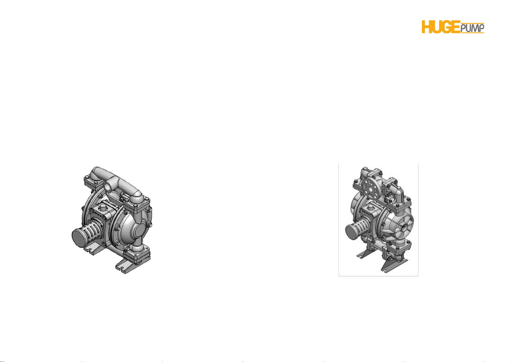
HP 10 PUMPS DEVIDED INTO TWO CATEGORIES WHICH ARE:
METALLIC PUMPS PLASTIC PUMPS
Page 2
Page 3

HP 10 PUMP USER’S MANUAL
COMPRESSED AIR DOUBLE DIAPHRAGM
TRANSFER PUMPS
TABLE OF CONTENT
METALLIC PUMP’S PERFORMANCE CURVES 4
AIR LINE MOISTURE 21
METALLIC PUMP’S DIMENSIONS 5
METALLIC PUMP’S PACKAGING 6
METALLIC PUMP’S SPARE PARTS DRAWINGS 7
METALLIC PUMP’S SPARE PARTS LIST 8
PLASTIC PUMP’S PERFORMANCE CURVES 10
PLASTIC PUMP’S DIMENSIONS 11
PLASTIC PUMP’S PACKAGING 12
PLASTIC PUMP’S SPARE PARTS DRAWINGS 13
PLASTIC PUMP’S SPARE PARTS LIST 14
DIAPHRAGM MATERIALS 16
PRINCIPLE OF PUMP OPERATİON 17
INSTALLATION &START UP 17
AREAS OF APPLICATION 19
AIR CONNECTION 21
AIR VALVE LUBRICATION 21
AIR INLET AND PRIMING 21
FREQUENCY OF USE 22
TROUBLESHOOTING 22
WARNINGS 23
PUMPING HAZARDOUS LIQUIDS 25
AIR VALVE ASSEMBLY 26
AIR VALVE MAINTENANCE 27
PILOT VALVE ASSEMBLY 28
PILOT VALVE MAINTENANCE 29
DIAPHRAGM MAINTENANCE 30
INTERMEDIATE ASSEMBLY MAINTENANCE 32
METALLIC CHECK VALVE MAINTENANCE 33
PLASTIC CHECK VALVE MAINTENANCE 34
ADRESS 35
Page 3
Page 4
0
1
2
3
4
5
6
7
0 20 40 60 80 100
160
140120
4,1 bar
5,5 bar
2,8 bar
1,4 bar
Basma Yüksekliği
( bar)
10 m3/h (hava giriş debisi)
6,7 bar (hava giriş basıncı)
Dakikadaki Litre Kapasitesi ( lt/dk)
67 m3/h
50 m3/h
40 m3/h
35 m3/h
20 m3/h
16 m3/h
Suction / Discharge 1"
Max. Capacity 150 lpm
Max. Solid particle
permeability (4 mm)
Max. Operation pressure
7 bar
Weight 9 kg (Aluminum)
Volumetric Capacity - LPM
Pump Head
HP 10 PUMP USER’S MANUAL
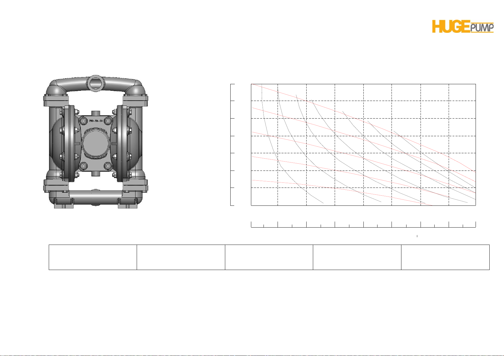
HP 10 (1”) METALLIC PUMP PERFORMANCE CURVES
HP 10 (1”) METALLIC PUMP
The operation pressure is 0 to 7 bars.
Operation temperature is between (-18 ˚Cand 100 ˚C.)
Page 4
Page 5
HP 10 PUMP USER’S MANUAL
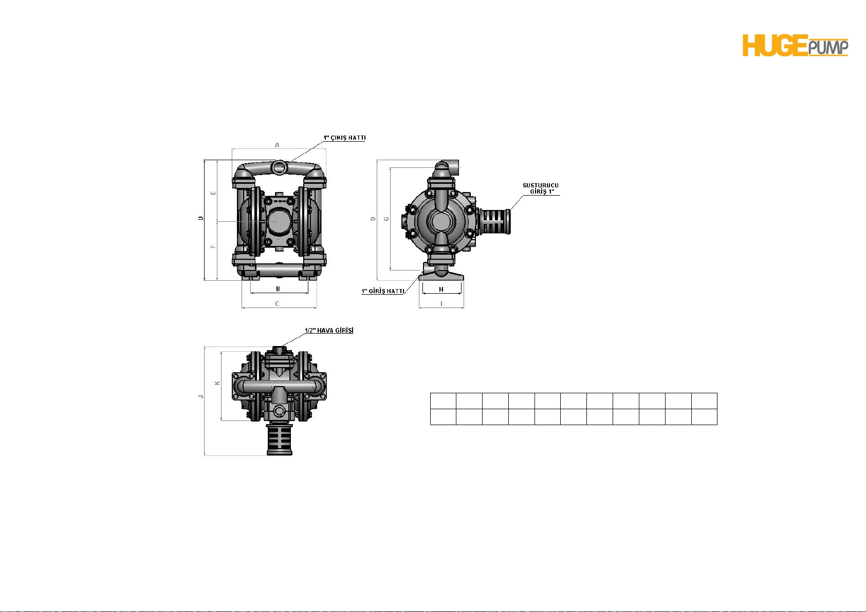
A B C D E F G H I J K
273
166
216
348
179
169
298
112
130
315
200
METRIC DIMENSIONS [ mm ]
Dimensional tolerances ± 3 mm
Page 5
Page 6
HP 10 PUMP USER’S MANUAL
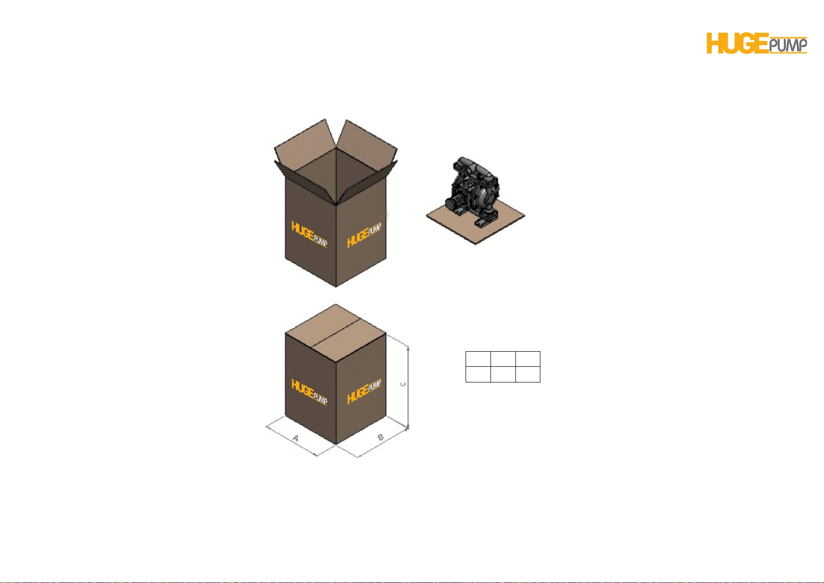
A B C
390
350
550
PACKING DIMENSIONS[ mm ]
Page 6
Page 7
HP 10 PUMP USER’S MANUAL
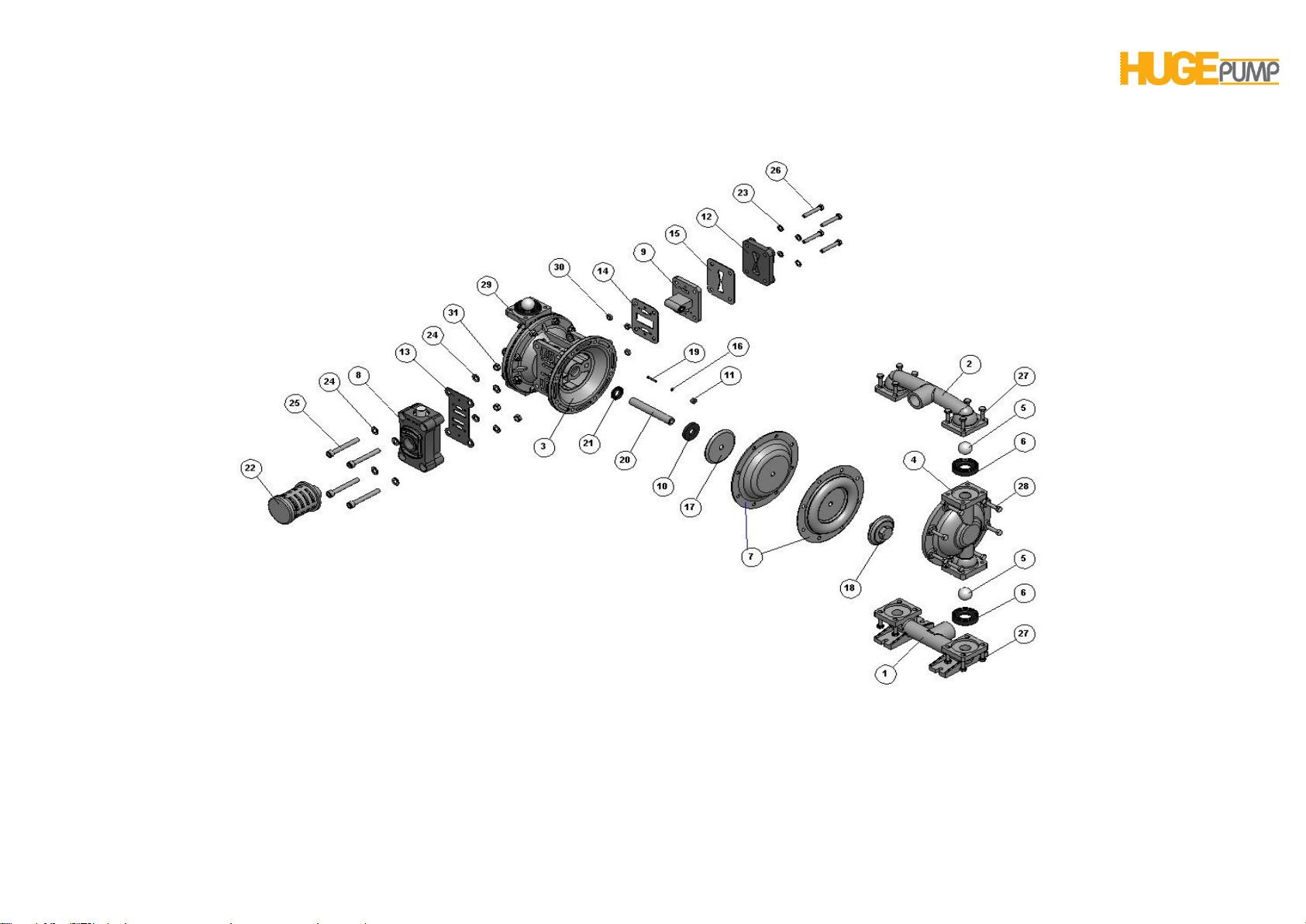
COMPOSİTE PARTS DRAWING OF HP 10 (1”) METALLIC PUMP
Page 7
Page 8

HP 10 PUMP USER’S MANUAL
METALLIC PUMP COMPOSITE PARTS LIST
1 S011030 Suction Line 1
S011031 Suction Line 1
S011032 Suction Line 1
2 S021030 Discharge Line 1
S021031 Discharge Line 1
S021032 Discharge Line 1
3 H011033 Main Body 1
4 S031030 Outer Chamber 2
S031031 Outer Chamber 2
S031032 Outer Chamber 2
5 S041045 Check Ball 4
S041046 Check Ball 4
S041047 Check Ball 4
S041048 Check Ball 4
S041050 Check Ball 4
S041051 Check Ball 4
6 S051036 Check Ball Seat 4
S051045 Check Ball Seat 4
S051046 Check Ball Seat 4
S051047 Check Ball Seat 4
S051048 Check Ball Seat 4
S051050 Check Ball Seat 4
S051051 Check Ball Seat 4
7 S061045 Diaphragm 2
S061046 Diaphragm 2
S061047 Diaphragm 2
S061048 Diaphragm 2
S061050 Diaphragm 2
S061051 Diaphragm 2
8 H034033 Air Valve Repair Kit 1
9 H044033 Pilot Valve Repair Kit 1
10 H051047 Bumper 2
11 H061036 Pin Bushing 2
12 H071033 Cover, Air Inlet Assembly 1
13 H084047 Gasket, Air Valve 1
14 H091047 Gasket, Pilot Valve, Front 1
15 H104047 Gasket, Pilot Valve, Rear 1
16 H124047 O-ring, Pin 2
17 H131030 Inner Diaphragm Holder 2
18 S071032 OuterDiaphragm Holder 2
S071033 OuterDiaphragm Holder 2
19 H141090 Actuator Pin 2
20 H151090 Diaphragm Rod 1
21 H161047 Oil Seal 2
22 H174036 Muffler 1
23 PM8-P Washer, M8 4
PM8 Washer, M8 4
24 PM10-P Washer, M10 8
PM10 Washer, M10 8
25 CM10X80-Pİ Capscrew M 10 X 80 (imbus)4
CM10X80 CapscrewM 10 X 80 (imbus)4
26 CM8X50-P CapscrewM 8 X 50 4
CM8X50 CapscrewM 8 X 50 4
27 CM8X25-P CapscrewM 8 X 25 16
CM8X25 CapscrewM 8 X 25 16
28 CM8X45-P CapscrewM 8 X 45 16
CM8X45 CapscrewM 8 X 45 16
29 SM8-PF Ring Nut, M8, Flanged 16
SM8-F Ring Nut, M8, Flanged 16
Page8
Page 9

HP 10 PUMP USER’S MANUAL
30 SM8-P Ring Nut, M8 4
SM8 Ring Nut, M8 4
31 SM10-P Ring Nut, M8 4
SM10 Ring Nut, M8 4
MATERIAL CODES
30 ALUMINUM 45 NEOPRENE
31 CAST IRON 46 SANTOPRENE
32 STAINLESS STEEL 47 BUNA-N
33 POLYPROPYLENE 48 EPDM
34 DELRIN 50 TEFLON
35 PVDF 51 VİTON
36 POLYETHYLENE 70 DIA SPECIAL MATERIAL
38 BRONZE 90 STEEL
Page9
Page 10
HP 10 PUMP USER’S MANUAL
0
1
2
3
4
5
6
7
0 20 40 60 80 100
160
140120
4,1 bar
5,5 bar
2,8 bar
1,4 bar
Basma Yüksekliği
( bar)
10 m3/h (hava giriş debisi)
6,7 bar (hava giriş basıncı)
Dakikadaki Litre Kapasitesi ( lt/dk)
67 m3/h
50 m3/h
40 m3/h
35 m3/h
20 m3/h
16 m3/h
Suction / Discharge 1"
Max. Capacity 150 lpm
Max. Solid particle
permeability (4 mm)
Max. Operation pressure
7 bar
Weight 7,5 kg (Plastic)
Volumetric Capacity - LPM
Pump Head
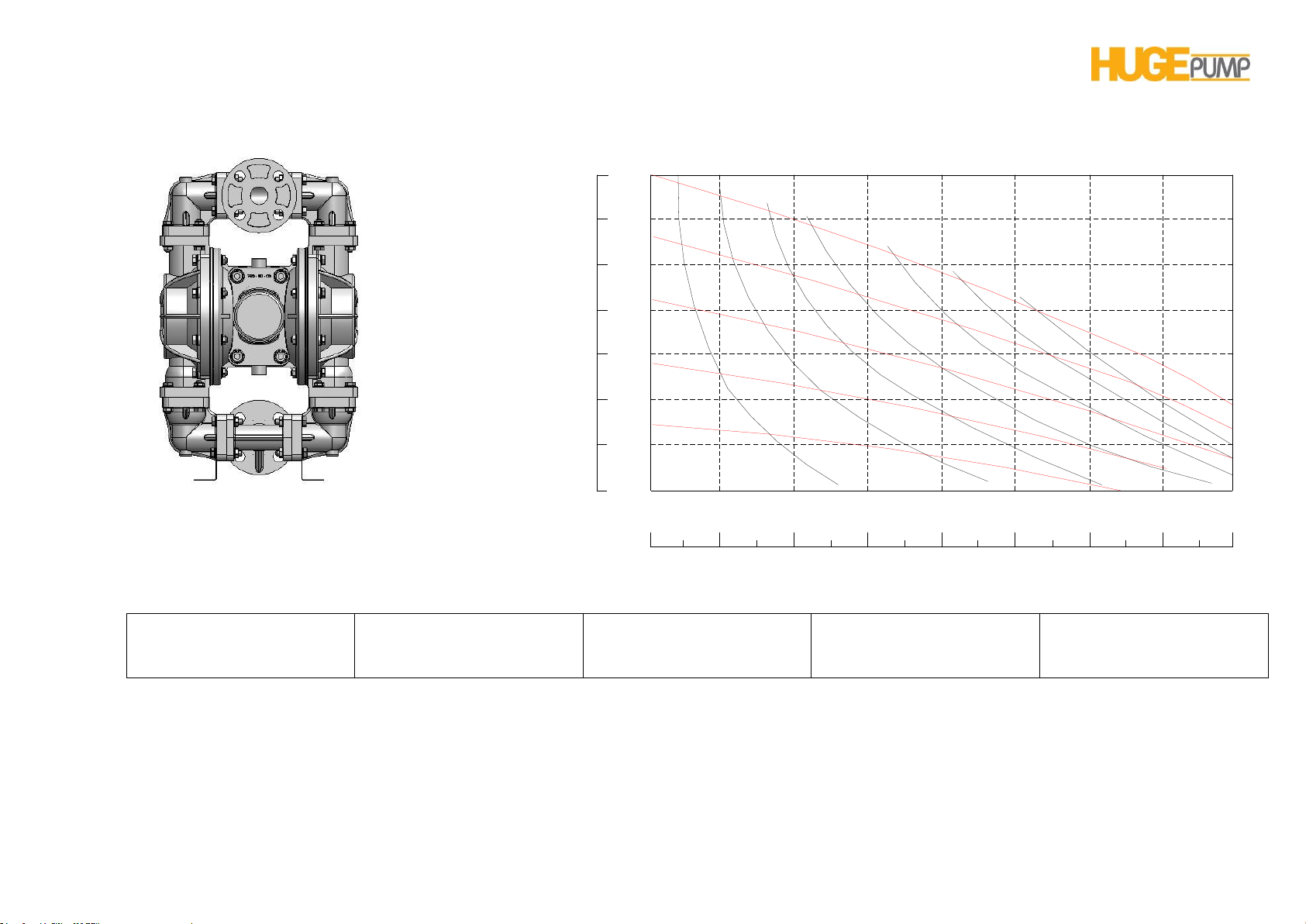
HP 10 PLASTIC PUMP PERFORMANCE CURVES
HP 10 (1”) PLASTIC PUMP
The operation pressure is 0 to 7 bars.
Operation temperature is between (-18 ˚Cand 100 ˚C.)
Page10
Page 11
HP 10 PUMP USER’S MANUAL
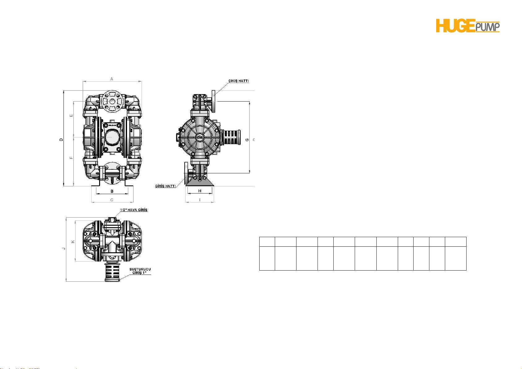
A B C D E F G H I J K
288
156,5
206,5
471
176,5
239,5
353,5
120
140
315
201,5
METRIC DIMENSIONS [ mm ]
Dimensional tolerances ± 3 mm
Page11
Page 12
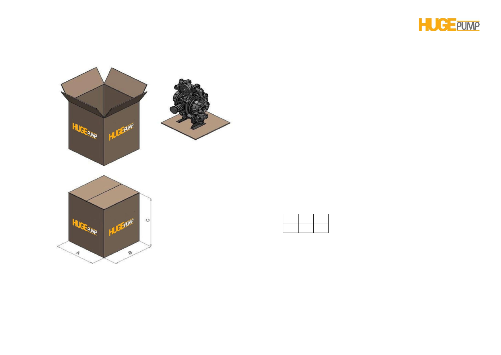
HP 10 PUMP USER’S MANUAL
A B C
390
390
550
PACKING DIMENSIONS [ mm ]
Page12
Page 13
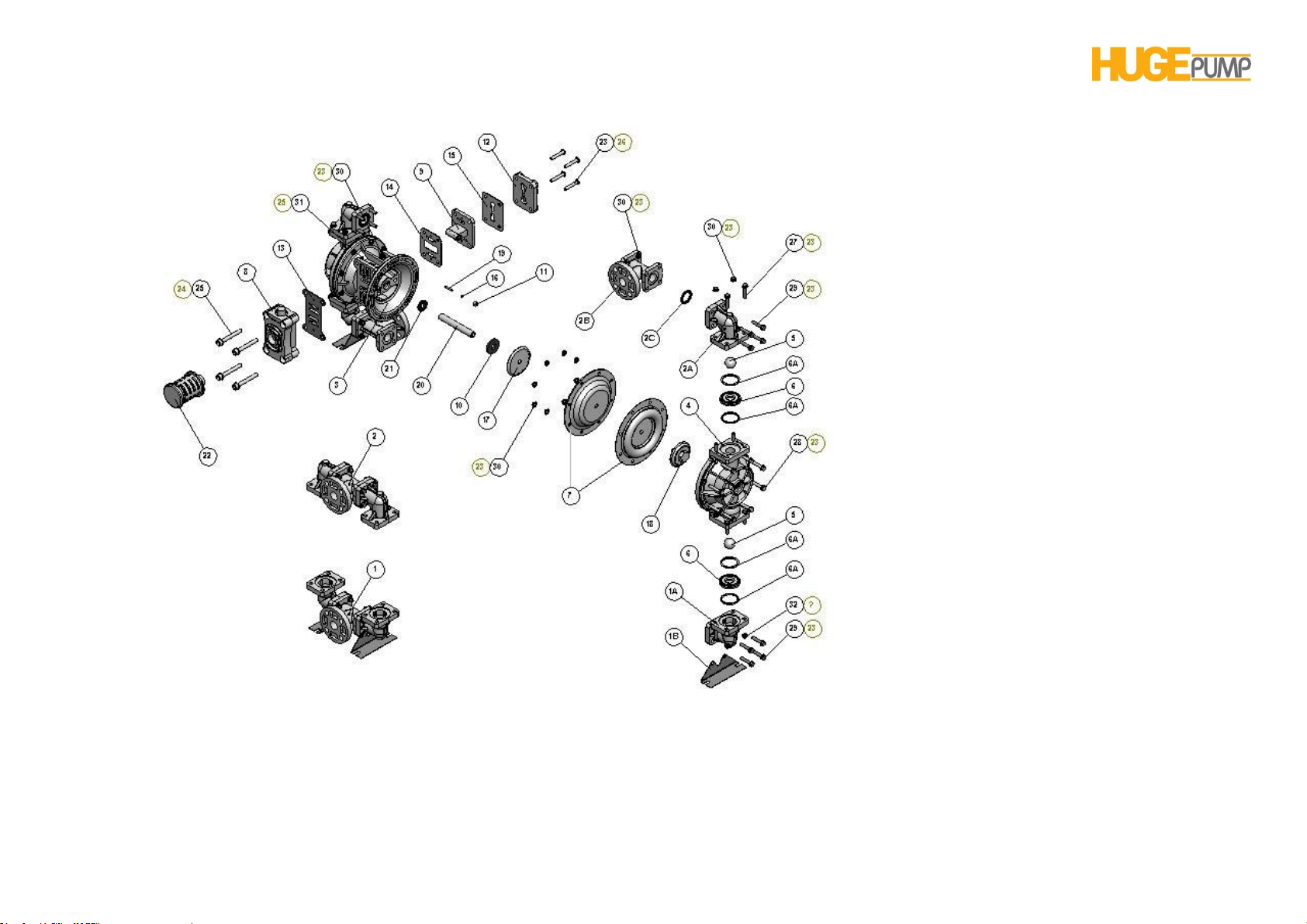
HP 10 PUMP USER’S MANUAL
COMPOSİTE PARTS DRAWING OF HP 10 (1”) PLASTIC PUMP
Page13
Page 14

HP 10 PUMP USER’S MANUAL
PLASTIC PUMP COMPOSITE PARTS LIST
1 S011033 Suction Line 1
S011035 Suction Line 1
1-A S261033 Suction Line Elbow 2
S261035 Suction Line Elbow 2
1-B S301032 Bracket 2
2 S021033 Discharge Line 1
S021035 Discharge Line 1
2-A S601033 Discharge Line Elbow 2
S601035 Discharge Line Elbow 2
2-B S241033 T Flanged 2
S241035 T Flanged 2
2-C S161050 Bracket Gasket 4
3 H011033 Main Body 1
4 S031033 Outer Chamber 2
S031035 Outer Chamber 2
5 S041045 Check Ball 4
S041046 Check Ball 4
S041047 Check Ball 4
S041048 Check Ball 4
S041050 Check Ball 4
S041051 Check Ball 4
6 S051033 Check Ball Seat 4
S051035 Check Ball Seat 4
6-A S081050 Check Ball Seat Gasket 8
7 S061045 Diaphragm 2
S061046 Diaphragm 2
S061047 Diaphragm 2
S061048 Diaphragm 2
S061050 Diaphragm 2
S061051 Diaphragm 2
8 H034036 Air Valve Repair Kit 1
9 H044036 Pilot Valve Repair Kit 1
10 H051047 Bumper 2
11 H061036 Pin Bushing 2
12 H071033 Cover, Air Inlet Assembly 1
13 H084047 Gasket, Air Valve 1
14 H091047 Gasket, Pilot Valve, Front 1
15 H104047 Gasket, Pilot Valve, Rear 1
16 H124047 O-ring, Pin 2
17 H131090 Inner Diaphragm Holder 2
18 S071033 Outer Diaphragm Holder 2
S071035 Outer Diaphragm Holder 2
19 H141090 Actuator Pin 2
20 H151090 Diaphragm Rod 1
21 H161045 Oil Seal 2
22 H175036 Muffler 1
23 PM8-P Washer, M8 100
PM8 Washer, M8 100
24 PM10-P Washer, M10 8
PM10 Washer, M10 8
25 CM10X80-Pİ Capscrew M 10 X 80 (imbus)4
CM10X80-İ Capscrew M 10 X 80 (imbus)4
26 CM8X50-P Capscrew M 8 X 50 4
CM8X50 Capscrew M 8 X 50 4
27 CM8X40-P CapscrewM 8 X 40 16
CM8X40 CapscrewM 8 X 40 16
28 CM8X45-P Capscrew M 8 X 45 16
CM8X45 Capscrew M 8 X 45 16
29 CM8X35-P Capscrew M 8 X 35 16
CM8X35 Capscrew M 8 X 35 16
Page14
Page 15

HP 10 PUMP USER’S MANUAL
30 SM8-P Ring Nut, M8 52
SM8 Ring Nut, M8 52
31 SM10-P Ring Nut, M8 4
SM10 Ring Nut, M8 4
MATERIAL CODES
30 ALUMINUM 45 NEOPRENE
31 CAST IRON 46 SANTOPRENE
32 STAINLESS STEEL 47 BUNA-N
33 POLYPROPYLENE 48 EPDM
34 DELRIN 50 TEFLON
35 PVDF 51 VİTON
36 POLYETHYLENE 70 DIA SPECIAL MATERIAL
38 BRONZE 90 STEEL
Page15
Page 16
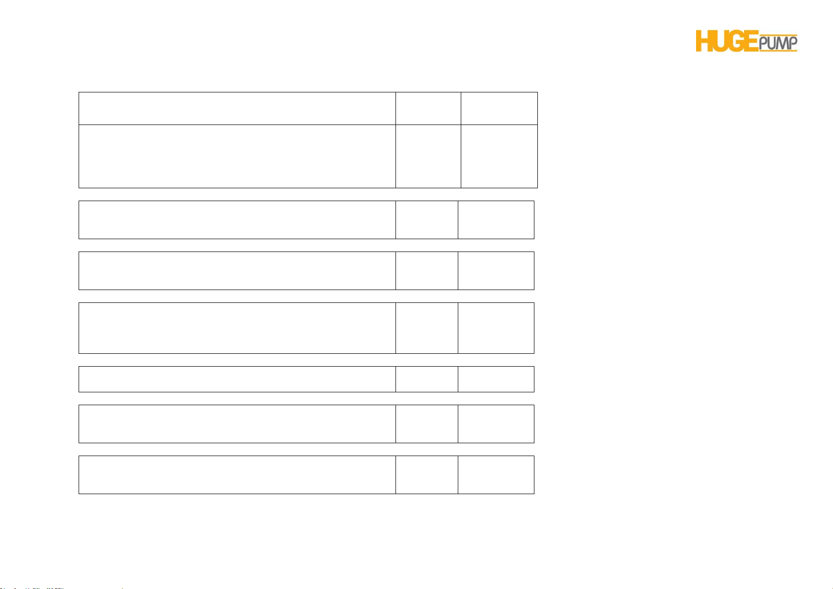
HP 10 PUMP USER’S MANUAL
Material
Maximum
Minimum
Neoprene
It is resistant to the vegetable oils. Its abrasion resistant is very
good. The fluids like acids, esters, ketones can cause damages
to the material of construction and therefore they are not
recommended.
90 ˚C
-22 ˚C
Buna-N
It is generally used for oils. It is very durable to the transfer of
water and hydraulic oil.
87 ˚C
-22 ˚C
EPDM
It is durable to chemicals. It is not durable to oil and solvents. It
has moderate resistance to the alcohols and ketones.
138 ˚C
-40 ˚C
Teflon
It is generally used for heavy chemicals and acids. It features
good resistance. It is suitable for heat transfer at elevated
temperatures.
100 ˚C
-35 ˚C
Viton
It has very good resistance to acids, oils and solvents.
175 ˚C
-40 ˚C
Santopren
It is resistant to weak and medium acids. It features good
abrasion resistance.
135 ˚C
-40 ˚C
Polypropylene
It is resistant to chemicals. It is usually preferred for food,
chemicals and cosmetic products.
82 ˚C
0 ˚C
DIAPHRAGM MATERIALS AND OPERATION TEMPERATURES
Page16
Page 17
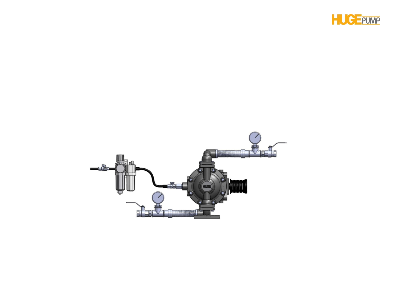
HP 10 PUMP USER’S MANUAL
PRINCIPLE OF PUMP OPERATION
The diaphragm pump is consisted of two diaphragm chambers and
two diaphragms.The diaphragms are connected to each other with a
diaphragm rod andmove in a reciprocating action.As one diaphragm
performs thedischarge stroke, the other diaphragm which is
connected with the rod ispulled to perform the suction.At the end of
the stroke, an airdistribution valve automatically shifts, reversing the
entire sequence, filling and pumping from alternate chambers. Mutual
movements that repeatedcontinuouslyensure suction and discharge
movements onto the fluids in each chamber.Continuously repeated
reciprocal motions pump the liquid during entering to andexitingfrom
the chambers.The flow of the fluid from one chamber to another is
regulated by the suction and discharge valves.
The ball and butterfly valves automatically controls the fluid suction
and discharge of the fluid.The butterfly valves allow passage of the
solid particles with a size up to diameter of the pipe.The ball valves
regulate passage of the small-size particles.
INSTALLATION &START-UP
Page17
Page 18

HP 10 PUMP USER’S MANUAL
The interconnections of the diaphragm pump are straightforward.The
fluid is taken from the bottom manifold and discharged at the upper
manifold.Diaphragm pumps are characterized by turbulence flow.To
prevent turbulence flow, the flexible hoses are installed upstream the
suction and the discharge port.
In order to observe the pressures at the suction and discharge parts
of the pump and adjust the flow rate,the manometers and valves are
attached at the suction and discharge ports. When one or both valves
are closed down, the pump will be stopped.When they are opened,
the operation will be resumed.
For the pump operation, the pressurized air is required.The pump is
operated at the full capacity, if the suction and discharge hoses are
the same size.A conditioner should be installed at the suction
port.The conditioner will allow the pressure adjustment and
lubricating the air direction valve.The valve installed downstream the
air inlet line the air flow is regulated by the valve operation.
Special precautions should be observed in the operation of
diaphragm pump.These precautions will provide the maximum
efficiency to thethe pump.
The pump should be located as close to the product being
pumped as possible.
The suction line length and number of fittings should be kept in a
minimum.
The size of the suction pipe should not less than the size of the
suction port of the pump.
For installations of rigid piping, short sections of flexible hose
should be installed between the pump and the piping.
The flexible hose reduces vibration and strain to the pumping
system.
The buffer tank should be provided at the discharge port of the
pump if discharge pipe assembly is long.The buffer tank will reduce
transfer of the vibration in the pipe assembly onto the pump.
Page18
Page 19
HP 10 PUMP USER’S MANUAL
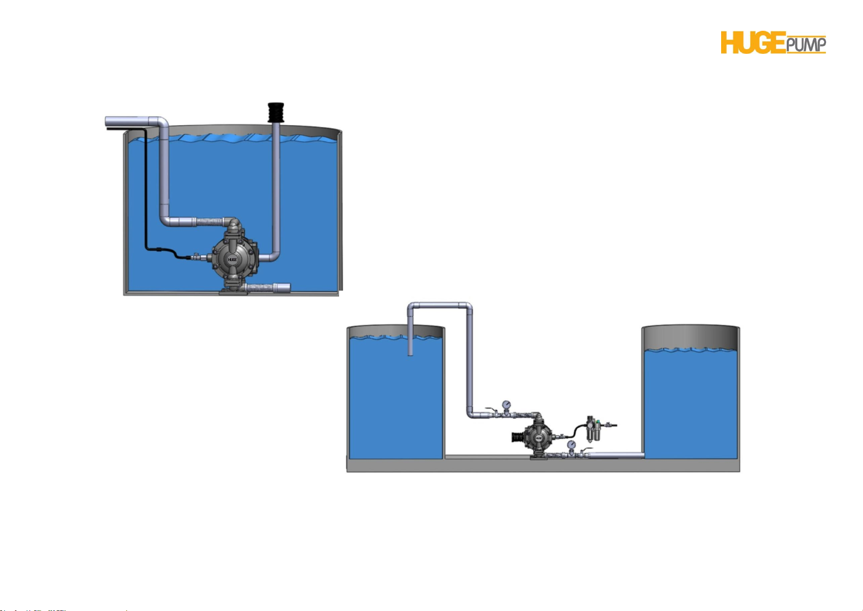
AREAS OF APPLICATION
Diaphragm pumps can be used to transfer
the fluid in the tank readily by connecting
them to the bottom of the tank.
Diaphragm pumps can also be used as submerged pump.
It is necessary to maintain the exhaust port of the pump
above the liquid surface with pipe or hose.
Page19
Page 20
HP 10 PUMP USER’S MANUAL
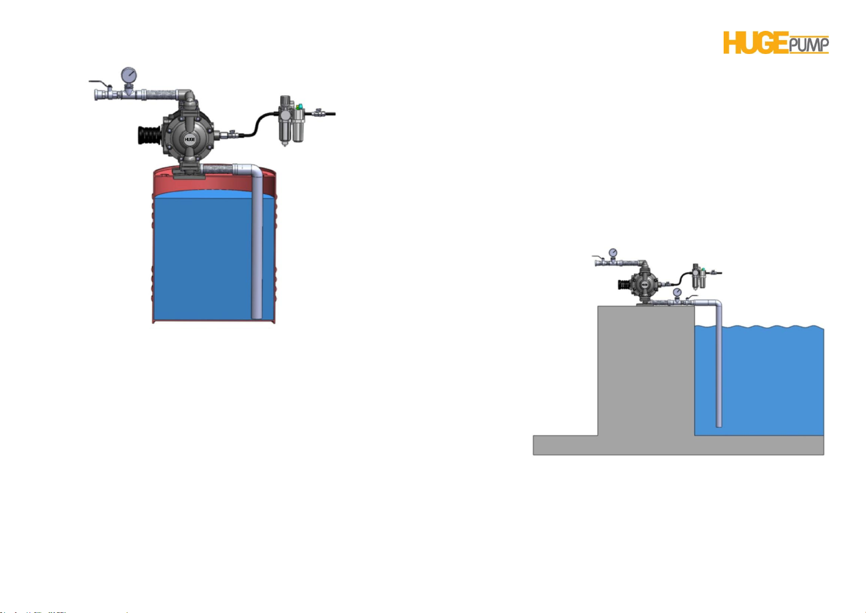
Diaphragm pumps can also be used as barrel pumps.
They have effective suctions ability and able to transfer
allthe fluid in the barrel.
The diaphragm pumps are able to transfer fluids at 6 meter of deepness.
Cavitation might obstruct the operation.To prevent this, the air in the hose between
the pump and fluid should be discharged.
Page20
Page 21

HP 10 PUMP USER’S MANUAL
WARNING If the size of air connection is
smaller than the pump supply port, the
pump will not be able to provide the air
required so, it will not perform properly.
AIR CONNECTION
The air pressure should not be in excess 7 bars.The pump should be
provided with the air supply at such pressure and flow to achieve
desired performance.When the airsupply line is solid piping, use a
short length of flexible hose not less than ½"in diameter between the
pumpand the piping to reduce strain to thepiping. The weight of the
air supply line, regulators and filters must be supportedby some
means other than the airinlet cap. Otherwise, unsupportive weight
may result in damageto the pump. A pressure regulatingvalve should
be installed to insureair supply pressure does not
exceedrecommended limits.
AIR VALVE LUBRICATION
The air distribution valve and the pilot valve are designed to operate
without lubrication. This is the preferred modeof operation. In regard
to anticipated practice or inferior air quality, it is likely include
lubrication oil into the compressed air. The pump air system will
operate withproperly lubricated compressed airsupply. Proper
lubrication requires theuse of an airline lubricator system to deliver
one drop of SAE 10 oil for every 10 liters/sec. of airconsumed by the
pump at the operation point.For better determination of the mixing
ratios, see the performance curves provided for the pump.
AIR LINE MOISTURE
Water in the compressed air supply might give rise to problem like
freezing of the water or icing in the discharge line thatcausethe pump
to cycle erratically or stopoperating.These problems might be
removed by using a point-of-use air dryer to supplement the user’s
airdrying equipment.The air drying equipment will removes the water
andalleviates problems like, freezing or icing.
AIR INLET AND PRIMING
Before operating the pump, turn the air supply valve at about 1/2 or
3/4 of a turn.Afterthe pump primes, the air valve can be opened to
increase air flow as desired.. If opening of the valve increases of the
reciprocating frequency without increase in air flow, then it means
that the pump operates under cavitation. In such cases, the
valveshould be closed slightly to obtain themost efficient air flow to
pump flowratio.
Page21
Page 22

HP 10 PUMP USER’S MANUAL
FREQUENCY OF USE
The pump should be flushed after each application to prevent its
damage if the pump is used for the transfer of the fluid that contains
suspended particles that settle and harden in the course of time when
it is kept stand still.(Otherwise, product remaining in thepump
between uses could dry out orsettle out. This could cause
problemswith the diaphragms and check valvesat restart.) The pump
should be completely drained after every use in particular under
freezing temperatures.
PUMP PROBLEMS AND SOLUTIONS
PROBLEM: The pump fails to operate even the air is supplied.The
supplied air is directly exit through the exhaust filter.
SOLUTION: Check the air valve of the pump.The piston of the linerpiston assembly of the air valve may be jammed.Disassembly the air
valve thenremove, clean and lubricate the piston of the liner-piston
assembly.Wipe off and lubricate the liner.Install the piston in the liner
and break in a while.Install the air valve back and start the pump.
PROBLEM: The pump operates but no flow is transferred.
SOLUTION: Check the valves of the pump.The valve plunger may be
jammed by the foreign matters.In such case, no transfer of the fluid is
possible.
PROBLEM: The pump is in operation, but the capacity of the fluid is
insufficient.
SOLUTION: There might be several reasons:
* The pump suction and discharge port sizes are not proper.In such
case, the air flow for the pump operation will be insufficient.
* The air flow is less than the required volumetric rate.It is likely that
the compressor falls short in supplying required air.
* The cross sectional area of the pump at the suction and discharge
ports might be contracted.Any contraction of the pump’s suction and
discharge ports might cause a drop in the real pump’s capacity.
PROBLEM: The pump transfers the fluid, but the flow is fluctuating.
SOLUTION: Check the pilot valve and air valve of the pump.
O-rings of the piston of the pilot valve may be worn out.If this is so,
replace the pilot valve.
* The piston in the air valve might be worn out.Disassemble the
piston and liner assembly of the air valve and lubricate before
reassembling.If the problem still persists, than replace the assembly
completely.
PROBLEM: There is excessive vibration in the pump during the fluid
transfer.
SOLUTION: There might be several reasons and solutions for that.
* High exit pressure of the pump and lack of rubber mountings on the
pump’s pedestals.
* Long discharge pipe and lack of compensators on the pipe installed
at specific intervals to prevent vibration.
* Use of flexible adaptors at the suction and discharge ports of the
pump
Page22
Page 23
HP 10 PUMP USER’S MANUAL
WARNING: Check all the connections with gaskets
for any looseness before operating the pump. Any
loose connection must be tightened to prevent any
leakage
WARNING: Check all capscrews and ring nuts for
tightness before operating the pump for the first
time.
WARNING. Operate the pump with a conditioner
installed at in front of the pump.
WARNING: Lubricate the pump continuously with
the conditioner. In order to prevent effluent water
from the air line, in addition to usage of the
conditioner, discharge the water accumulated in the
compressor tank.
WARNING: Be sure not to tighten excessively to the
capscrews during the assembly and disassembly;
otherwise the pump’s main body may be damaged.
WARNING: The silencer must be used while
operating the pump.
IMPORTANT
Read these safety warnings and instructions in thismanual completely, beforeinstallation and start-up of the pump.It is the user’s responsibility to
retain this manual.Any operation performed that is not in according to the information provided under the manual may render the pump’s warranty
invalid.
WARNINGS
Page23
Page 24
HP 10 PUMP USER’S MANUAL
WARNING: Please be careful at the pump transfer.
WARNING: The fittings should be installed to
eliminate any possible leakage of the transferred
liquid.
WARNING: The pump should be installed onto the
rubber mountings.
WARNING: In order to prevent the knock at the
discharge, the pump should be complete with the
flexible hose adaptor at the discharge port where the
pipe assembly is long.
WARNING: Take action to prevent static sparking.
Fire or explosion can result, especially when handling
flammable liquids. The pump, piping, valves,
containers or other miscellaneous equipment must be
grounded.
WARNING: Be sure using the gloves and goggles
in the pump repair and maintenance works.
WARNING: The air supply should be switched off
before any repair or maintenance of the pump. Then
pump pressure should be released and air connection
be removed. Be carefulcompressed air line.
WARNING: When used for toxic or aggressive
fluids, the pump should always be flushed with
water before the repairment.
Page24
Page 25

HP 10 PUMP USER’S MANUAL
WARNING: If the diaphragm is split then, the
transferred fluid may pass to the air side of the pump
and diffuse to the atmosphere.If pumping a product
which is hazardous or toxic, the air exhaust must be
piped to an appropriate area for safe disposition.
NOTE:Contact to our company in case of any failure of the pump provided under the warranty.2-year warranty will be terminated if the pump is
dismantled without notifying to our company.
PUMPING HAZARDOUS LIQUIDS
When a diaphragm fails, the pumpedliquid or fumes enter the air end
ofthe pump. Fumes may dissipate in the ambient air.Whenpumping
hazardous or toxic materials,the exhaust air must be piped to
anappropriate area for safe disposal.
If the material of construction of the pump is compatible to the liquid
being pumped, the pump can be submerged into the fluid.In such
Page25
case,the air exhaust must bepiped above the liquid level. The size of
the pipe for air discharge should be at least 1” diameter.Reducingthe
pipe size will reduce air flow and pump performance.If the liquid to be
transferred is at higher lever than the pump (flooded
suctioncondition), the discharge port should be kept at a higher level
then the liquid surface to prevent siphoning spills.
Page 26
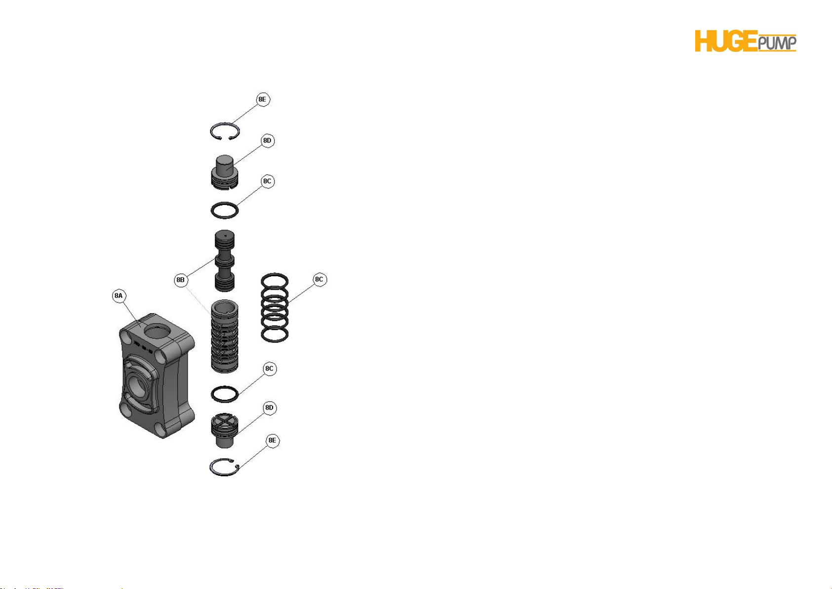
HP 10 PUMP USER’S MANUAL
AIR VALVE ASSEMBLY( H034033B )
8 PART LIST OF AIR VALVE REPAIR KIT
Item No. Part No. Name of Part Qty
8A H554033B Air Valve Body 1
8B H594070 Sleeve and Spool Set 1
8C H574047 O-ring 8
8D H584033 Cap 2
8E H504090 Snap ring 2
Page26
Page 27

HP 10 PUMP USER’S MANUAL
AIR VALVE MAINTENANCE
To begin with the servicing of the air valve first shut off
thecompressed air, bleed pressure from thepump, and disconnect the
air supply line from the pump.
* First: inspect the exploded view of the air valve.
Remove four hex capscrews by using wrench or socket.Remove the
air valve assembly from the pump.Remove the gasket and check to
see any cracking or damage.Replace the gasket if it is necessary,
* Second:Disassembly of the air valve.
Remove the snap rings of two plugs beneath the air valve with pliers
in order to have access to the internal parts of the air valve.Then
remove two caps.Check O-rings to see any abrasion or cuts.Replace
O-rings as neeeded.Take the the spool out of the sleeve. Be sure not
to scratch or damage the surface of the spool’s mating surface.Wipe
the spool with soft piece of cloth and check to see any scratch or
damage.Check inner surface of the sleeve to see any dirt, scratches
or other contaminants.Remove the sleeve and replace with a new
sleeve and spool assembly, as necessary.
* Third: reassembly of the air valve.
To do this, install one bumper together with its O-ring on the one side
of the air valve assembly. Check O-rings of the existing or new or
sleeve and spool set replaced as necessary.Carefully take the spool
out from the sleeve.Install six O-rings into the six grooveson the
sleeve.
Then install the liner onto the main housing of the air valve.Be sure to
apply a light coating of grease to the O-rings before installing
thesleeve into the valve body; alignthe slots in the sleeve with the
slots in thevalve body. Insert the spool into the sleeve.Be careful not
to scratch or damage the spool during installation.Install other
bumper together with its O-ring. Install the snap ring. The repair of the
valve is completed.During installing the complete with and gasket
onto the pump, be sure to have the holes of the valve in line with the
holes on the pump.Connect the compressed air line onto the
pump.The pump is now ready to operation.
Page27
Page 28
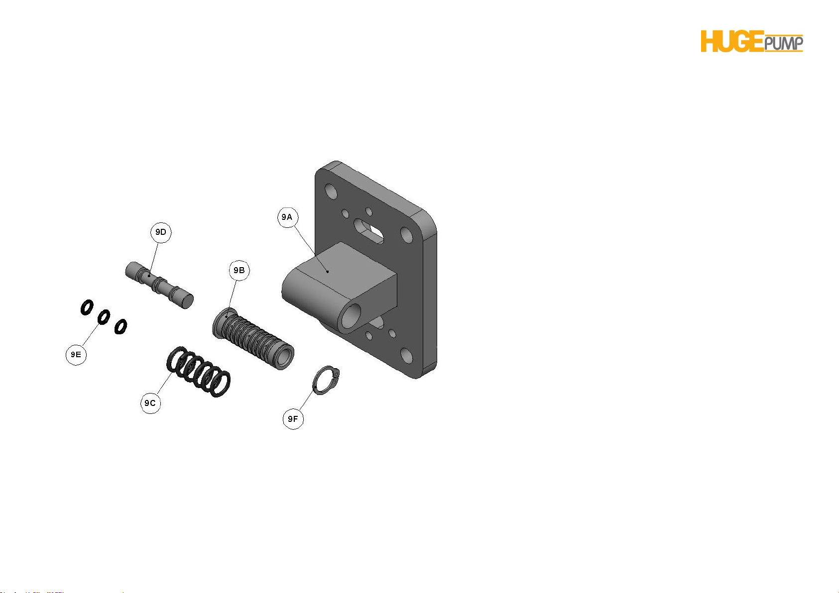
HP 10 PUMP USER’S MANUAL
PILOT VALVE ASSEMBLY( H044033B )
9 PART LIST OF PILOT VALVE REPAIR KIT
Item No. Part No. Name of Part Qty
9A H454033B Pilot Valve Body 1
9B H464090 Sleeve 1
9C H474047 O-ring, sleeve 6
9D H484090 Spool 1
9E H484047 O-ring, spool 3
9F S124090 Snap ring 1
Page28
Page 29

HP 10 PUMP USER’S MANUAL
PILOT VALVE MAINTENANCE
To begin with the servicing of the air valve first shut off the
compressed air, bleed pressure from the pump, and disconnect the
air supply line from the pump.
*First: See pump assembly drawings.
Remove four capscrews by using M8 spanner or socket wrench.
Remove air inlet cover and air inlet port gasket.The pilot valve
assembly may now be taken out for inspection and service.
*Second: Removal of the pilot valve.
Remove the spool of the valve.Wipe it to remove any dirt. Check the
spool and O-ring to see any dirt, cut or abrasion.Replace O-ring and
spool as necessary.Remove the snap ring from the end of the sleeve
and remove the sleeve from the valve body.Wipe it to remove any
dirt. Check the sleeve and O-ring to see any dirt, cut or
abrasion.Replace O-ring and liner, if needed.
Page29
*Third: Installing the pilot valve
Generously lubricate outside diameter of the sleeve and o-rings.
Then carefully insert sleeve into valve body.During the installation of
the sleeve, takeCAUTION not to damage O-rings.Install the snap ring
to sleeve. Lubricate the other surface of the piston and O-ring.Then
carefully install the spool into the sleeve.During the installation of the
piston, takeCAUTION not to damage O-rings.
*Fourth: Re-install the valve assembly into intermediate portion.
During installing the pilot valve assembly onto the intermediate
portion, be sure pilot valve ends located to the center of the piston
pins.Re-install the gasket, air inlet capand capscrews. Connect the air
supplyto the pump. The pump is now ready for operation.
Page 30
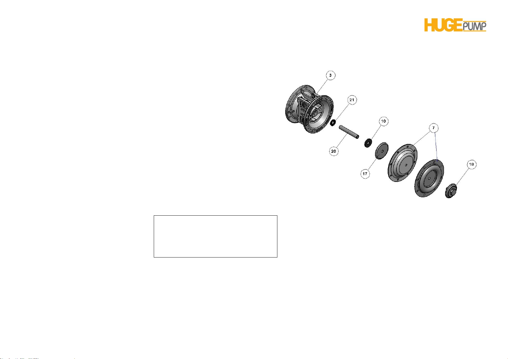
HP 10 PUMP USER’S MANUAL
Double diaphragms are used for the
pump with Teflondiaphragm.The rubber
diaphragm which installed at the front
of the Teflondiaphragm provides,
supports and extends the service life.
DIAPHRAGM MAINTENANCE
Item No. Part No. Name of Part Qty
3 H011033 Main Body 1
21 H161047 Oil Seal 2
20 H151090 Diaphragm Rod 1
10 H051047 Bumper 2
17 H131090 Inner Diaphragm Holder 2
7 S061045 Diaphragm 2
18 S071033 OuterDiaphragm Holder 2
Page30
Page 31

HP 10 PUMP USER’S MANUAL
For maintenance of diaphragms, first remove the suction line of the
pump and than block the pump discharge line.Cut off the compressed
air supplybleed thepressure from the pump and disconnectthe air
supply line from the pump. Drainany remaining liquid from the
pump.Inspect the pump assembly drawings and maintenance
diagrams.Remove the manifolds.Remove the pump ball and ball
seats.Then remove the outer covers of the pump.
*First: Removal of diaphragm assemblies
Use M16 wrench or socket to unscrew the outer diaphragm holder by
turning counterclockwise direction and remove the diaphragm
assembly from thediaphragmrod.Then take onediaphragm together
with outer and inner diaphragm holders and the otherdiaphragm with
its diaphragm rod out.In order to disassembly first diaphragm with its
holder, hold the diaphragm assembly with a vice by clamping the
inner holder and remove the outer holder by turning it
counterclockwise with M16 spanner.
Hold the diaphragm rod of other diaphragm assembly with a vice and
dismantle diaphragm with a spanner.Perform dismantling the other
diaphragm in the same manner.Check the diaphragm for cuts,
bursting, abrasion and chemical corrosion.Replace the diaphragms
as necessary.
*Second: Installing diaphragms
Insert M16 capscrews onto the outer diaphragm holder and push the
diaphragm into the center hole. Install the capscrews onto inner
diaphragm holder and screw it onto the rod by turning clockwise.Hold
loose assembly with a vice.Screw M16 wrench with a spanner.
*Third: Installing diaphragm assembly onto pump
Make sure the bumper is installed over the diaphragm rod. Screw the
rod of the diaphragm assembly by turning clockwise into threaded
hole until it is in the same direction with the end of the inner
diaphragm plate. Insert rod into pump.Bring the capscrew holes on
the diaphragm in line with inner chamber capscrew holes.Install outer
chamber onto the pump by capscrews and ring nuts.
On the opposite side of the pump,pull the diaphragm rod out as far
aspossible. Make sure the second bumperis installed over the
diaphragm rod.Screw the exposed part of the diaphragm assembly
shaft in clockwise direction onto the diaphragm rod as much as
possible and leave the gap sufficient enough to adjust the capscrew
holes on the diaphragm in line with inner casing capscrew holes.
Install the part of outer casing onto the pump with capscrews, nuts
and washers. Install the manifolds onto the pump with capscrews,
nuts and washers. Perform the necessary connections onto the
pump. Now the pump is ready for the operation.
Page31
Page 32
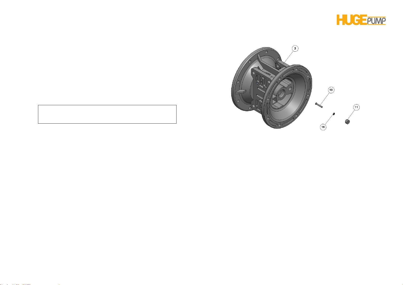
HP 10 PUMP USER’S MANUAL
In order to prevent damages at the high pressure
operation replace the actuator pin with new one. If this
situation continues use bigger size of actuator pin.
THRUST PIN MAINTENANCE
Item No. Part No. Name of Part Qty
3 H011033 Main Body 1
19 H141090 Actuator Pin 2
16 H124047 O-ring, pin 2
11 H061036 Pin Bushing 2
To begin with the maintenance of the actuator pin, firstthe
compressed air supply, bleed the pressure from the pump,
anddisconnect the air supply line fromthe pump.
*First: Inspect pump installation drawings
Remove four capscrews by using M8 spanner or socket wrench.
Remove the air inlet cap and air inlet gasket. The pilot valve
assembly can now beremoved.
*Second: Inspect actuator pins
See the assembly drawings.Access to the actuator pins can be
reached through the opening of the pilot valve assembly. Remove the
plungers fromthe bushings in each end ofthe cavity. Inspect the
installed o-ring for cuts and/or wear. Replace the o-rings, if it’s
necessary.Lubricate O-rings slightly and install the pins into the
bushing. Push the plungers in as far as they willgo.
*Third: Install the valve assembly into intermediate gap
During installing the pilot valve assembly onto the intermediate
portion, be sure pilot valve ends located to the center of the actuator
pins.Install the gasket, air inlet cover and capscrews.Connect the air
supply onto the pump.The pump is now ready for operation.
Page32
Page 33
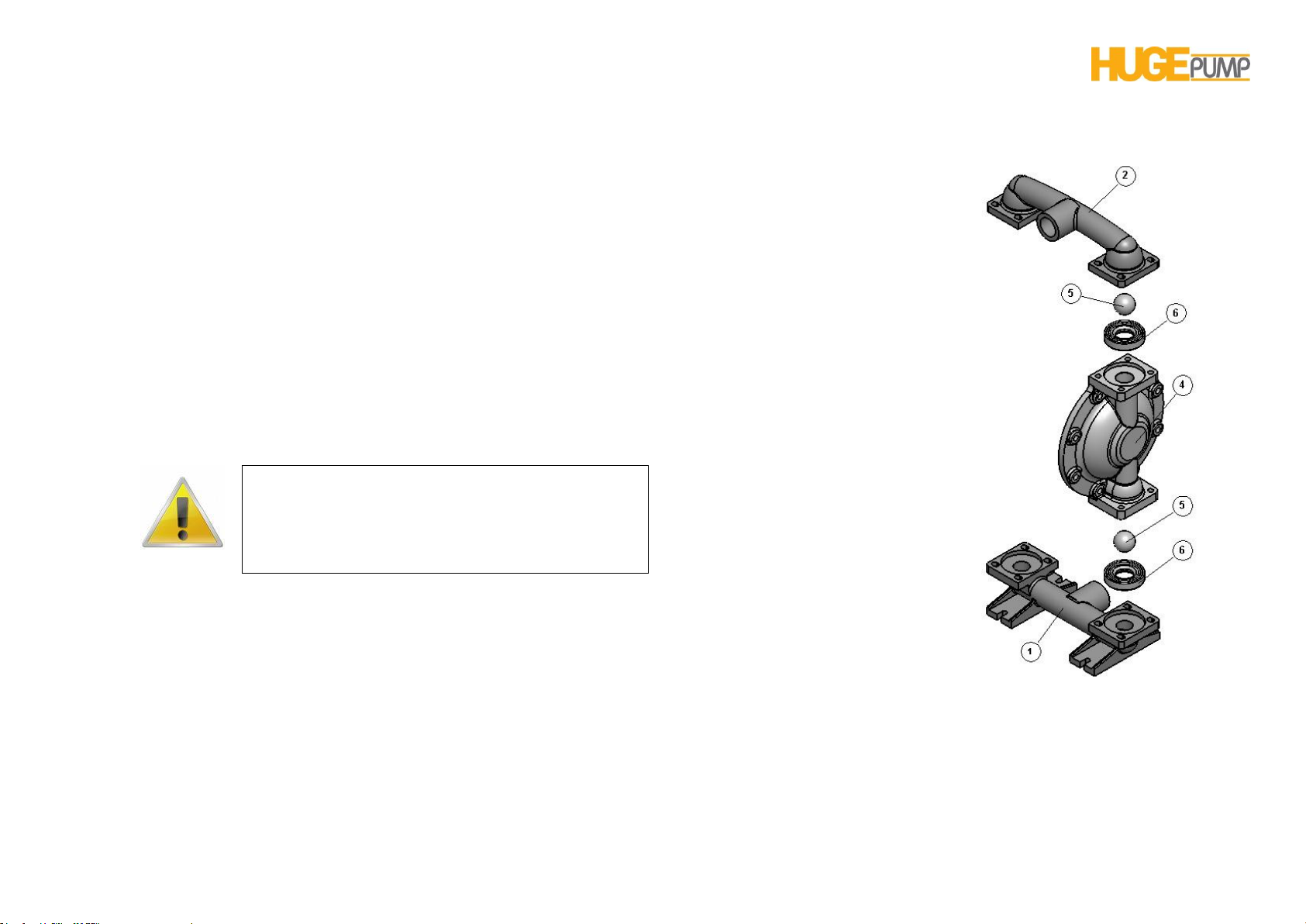
HP 10 PUMP USER’S MANUAL
WARNING: The air supply should be switched off
before any repair or maintenance of the pump. Then
pump pressure should be released and air
connection be removed. Be carefulcompressed air
line.
METALLIC CHECK VALVE (BALL & SEAT) MAINTENANCE METALLIC
Shut off the suction line and discharge line of the pump before
starting the maintenance work.Then shut the compressed air supply,
discharge the pressure in the pipe and remove the compressed air
connection.Discharge the fluid in the pump.Now the pump can be
disassembled for the maintenance.
Remove the manifold to have access to the check valves.
Inspect the check balls for any abrasion, cuts or corrosion
marks.Perform the same checks on the check valve seats to see any
cuts, abrasion and any foreign materials embedded onto the
surfaceof both the external and internal chambers.The
sphericalsurface of the check balls must seat flush to the surface of
the check valveseats for the pump to operate to peak efficiency.
The damaged or worn out
parts should be replaced as
necessary.Re-assemble
the parts of the check
valves.The seat should fit
into thecounter bore of the
outer chamber. Assemble
the pump and make
necessary connections.
The pump is ready for
operation.
Item No. Part No. Name of Part Qty
2 S021030 Discharge Line 1
5 S041047 Check Ball 4
6 S051045 Check Ball Seat 4
4 S031030 Outer Chamber 2
1 S011030 Suction Line 1
Page33
Page 34
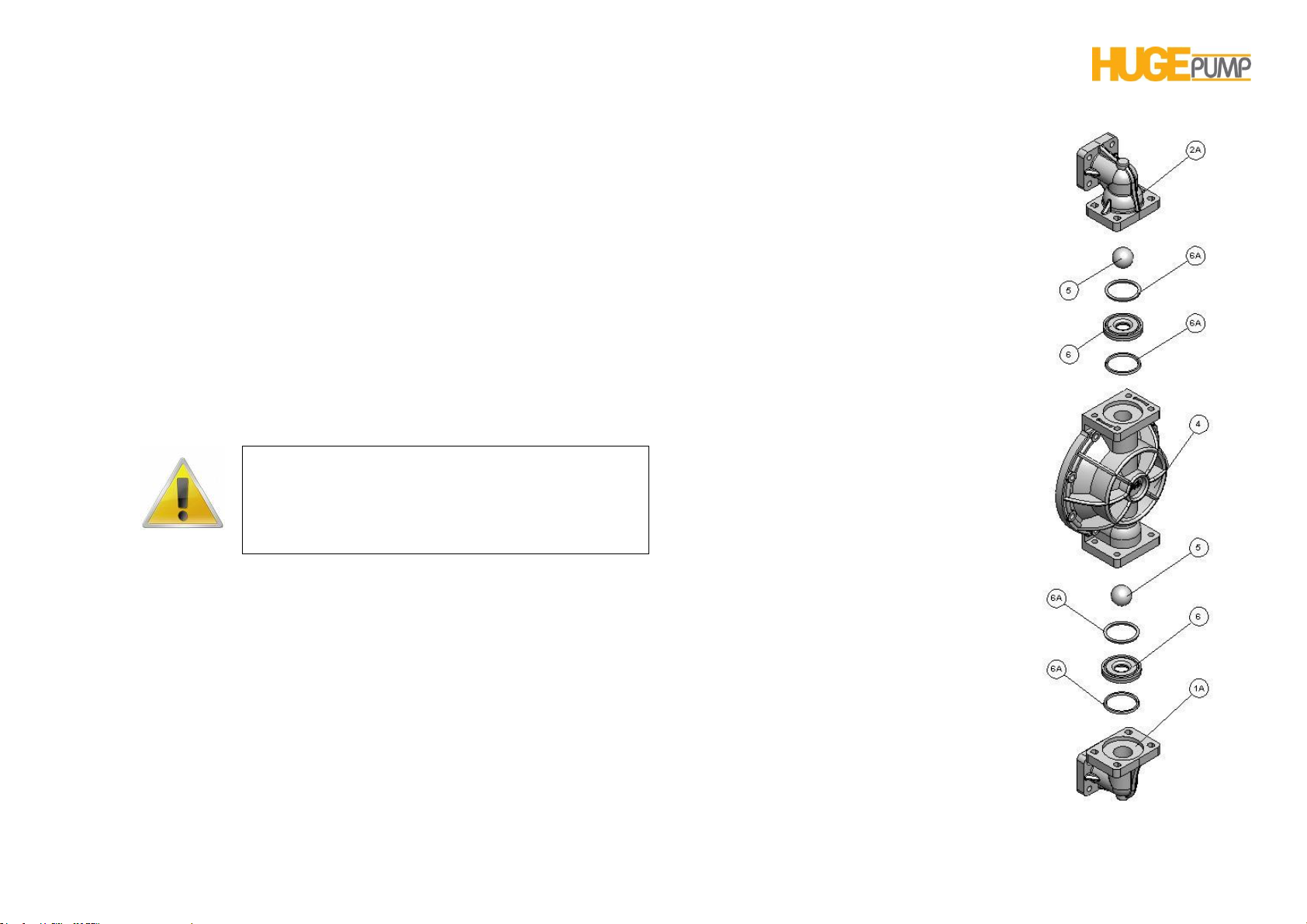
HP 10 PUMP USER’S MANUAL
WARNING: The air supply should be switched off
before any repair or maintenance of the pump. Then
pump pressure should be released and air
connection be removed. Be careful compressed air
line.
METALLIC CHECK VALVE (BALL & SEAT) MAINTENANCE PLASTIC
Shut off the suction line and discharge line of the pump before
starting the maintenance work. Then shut the compressed air supply,
discharge the pressure in the pipe and remove the compressed air
connection. Discharge the fluid in the pump. Now the pump can be
disassembled for the maintenance.
Remove the manifold to have access to the check valves.
Inspect the check balls for any abrasion, cuts or corrosion marks.
Perform the same checks on the check valve seats to see any cuts,
abrasion and any foreign materials embedded onto the surfaceof both
the external and internal chambers. The sphericalsurface of the
check balls must seat flush to the
surface of the check valveseats for
the pump to operate to peak
efficiency.
The damaged or worn out parts
should be replaced as necessary.
Re-assemble the parts of the check
valves.The seat should fit into
thecounter bore of the outer
chamber. Assemble the pump and
make necessary connections. The
pump is ready for operation.
Item No. Part No. Name of Part Qty
2A S601033 DischargeLineElbow 2
5 S041050 CheckBall 4
6A S081050 CheckBallSeatGasket 8
6 S051033 CheckBallSeat 4
4 S031033 Outer Diapragm 2
1A S261033 Suction Line Elbow 2
Page34
Page 35

HP 10 PUMP USER’S MANUAL
ADRESS
GÜNALSAN POMPA ve MAK. SAN. TİC. LTD. ŞTİ.
Adress: Maltepe Mah. Çifte Havuzlar Cd. Ayvalıdere Sok. No:6
Davutpaşa - Zeytinburnu / İstanbul
Tel : +90 212 613 41 42
Fax : +90 212 613 41 49
e-mail:[email protected]
Website: www.gunalsanpompa.com
Page35
 Loading...