

Page 1
1
07/01 P/N 211169A
printed on recycled paper
Backboard and Rim
Owners Manual
IMPORTANT! Have any questions?...Don’t go back to the store!
We appreciate your purchasing one of our many fine products. We are sure that you will be very satisfied with your selection. Although
great care and effort have been taken, occasionally problems may occur. To ensure prompt and correct handling of any problems, or to
answer any questions, please contact our Toll-Free Customer Service Number listed below. Service will be quicker if you have your
Model Number (found on carton) and assembly instructions ready when calling. PLEASE WRITE YOUR MODEL NUMBER IN THE
SPACE PROVIDED ABOVE.
A Huffy Sports Company
Customer Service Center
N53 W24700 South Corporate Circle
Sussex, WI 53089
U.S.A.
WRITE IN YOUR MODEL NUMBER:
Toll-Free Customer Service Number for U.S: 1-800-334-9111
Internet Address: http://www.hydra-rib.com
© COPYRIGHT 1999 by HUFFY SPORTS
TOOLS AND MATERIALS
REQUIRED
FOR ASSEMBLY:
• Two People
• Step Ladder, 8 ft. (2.4 m)
• Wrenches (Two)1/2” and
(Two) 9/16” or (Two) Adjustable
Wrenches
SAFETY INSTRUCTIONS
FAILURE TO FOLLOW THESE SAFETY INSTRUCTIONS MAY
RESULT IN SERIOUS INJURY,
PROPERTY DAMAGE AND WILL VOID WARRANTY.
Owner must ensure that all players know and follow these
rules for safe operation of the unit.
To ensure safety, do not attempt to assemble this system without
following the instructions carefully. Before beginning assembly, read
the instructions and identify parts using the hardware identifier and
parts list in this document. Proper and complete assembly, use and
supervision is essential for proper operation and to reduce the risk of
accident or injury. A high probability of serious injury exists if this
system is not installed, maintained, and operated properly.
• Read and understand the warning label enclosed with hardware. It is
the responsibility of the customer to mount this label. It should be
affixed to the pole, wall, or door near playing area, at a height between
4-6 feet above ground level and in a location visible to all players.
• During assembly, if using a ladder use extreme caution. Two people
are recommended for this operation.
• If technical assistance is required, contact Huffy Sports.
• Serious injury could occur if teeth/face come in contact with backboard,
net or rim.
• Minimum operational height is 6’6” to the bottom of backboard.
Most injuries are caused by misuse and/or not following instructions.
Use caution when using this unit.
For more information on assembly, placement, proper use and
maintenance, visit The American Basketball Council website at
http://www.smarthoops.com
Page 2
2
P/N 211169A 07/01
printed on recycled paper
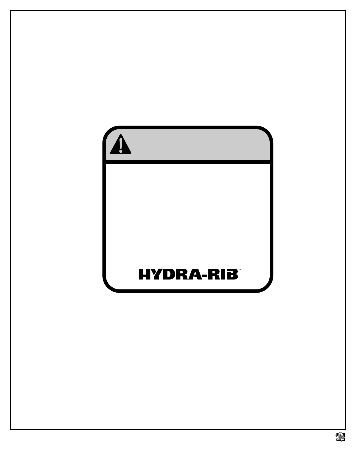
WARNING
FAILURE TO FOLLOW THESE WARNINGS MAY RESULT
IN SERIOUS INJURY AND/OR PROPERTY DAMAGE.
Owner must ensure that all players know and
follow these rules for safe operation of the unit.
·
See instruction manual for proper installation and
maintenance.
·
Use caution when performing dunk type activities on this unit.
·
Do not hang from any part of unit, including backboard,
support braces, rim or net.
·
Check unit before each use for loose hardware, excessive
wear and signs of corrosion and repair before using.
·
During play, use extreme caution to keep player's face away
from the backboard, rim or net. Serious injury could occur if
teeth/face come in contact with backboard, rim or net.
·
During play, do not wear jewelry (rings, watches, necklaces,
etc.) Objects may entangle in net.
In the U.S.: 1-800-334-9111
200160 1/00
Page 3
3
07/01 P/N 211169A
printed on recycled paper
Item #6 (12)
Item #3 (1)
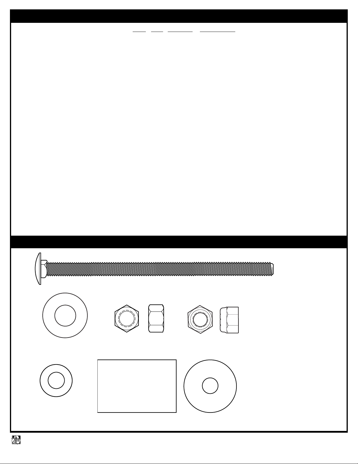
PARTS LIST
HARDWARE IDENTIFIER
Item Qty. Part No.
Description
11 Rim
2 1 220065 Bolt, Carriage 3/8 x 5.5” Long
3 1 203474 Washer, Flat, 1”O.D.
4 1 203017 Hex Nut, 3/8”
5 2 203063 Nylon Nut, 3/8”
6 12 203232 Washer, 3/4” O.D.
7 1 200484 Spring
8 1 220043 Concave Washer
9 1 201124 Center Lock Nut
10 1 220064 Spacer
11 1 203439 Bolt, Hex, 3/8 x 6” Long
12 2 201611 Screw, Self Tap
13 1 920262 Bracket - Orange
14 1 920038 Inner Bracket - Black
15 1 960043 Cover Plate - Orange
16 4 201611 Bolt, Hex, 5/16x3” Long
17 6 203100 Whiz Nut, 5/16”
18 1 204281 Net
19 1 220569 Label, Logo
20 2 206263 Bolt, Carriage 5/16-18 x 3” Long
21 4 220082 Washer, Rubber 3/8
22 2 203274 Foam Pad 3/32 x 5 x 5
23 2 205224 Foam Pad, .125 x 21 x 1
Item #7 (1)
Item #4 (1)
Item #2 (1)
Item #5 (2)
HARDWARE IDENTIFIER (CONTINUED)
Page 4

4
P/N 211169A 07/01
printed on recycled paper
HARDWARE IDENTIFIER (continued)
Item #9 (1)
Item #12 (2)
Item #20 (2)
Item #17 (6)
Item #16 (4)
Item #21 (4)
Item #10 (1)
Item #11 (1)
Item #8 (1)
Page 5

5
07/01 P/N 211169A
printed on recycled paper
1.
Attach foam pad (22) to both front and back of backboard so that holes on pad line up with holes on backboard as
shown. Attach foam pad (23) to both Y-frame sections as shown. Lift backboard upright and insert bolt (20)
through board into Y-frame. Attach using rubber washer(21), and nut (17) as shown.
17
TWO PERSON MINIMUM
REQUIRED FOR THIS
PROCEDURE.
NOT FOLLOWING
RECOMMENDATION MAY
RESULT IN BODILY INJURY.
WARNING
20
21
21
RIM ASSEMBLY & INSTALLATION
2.
Install carriage bolt (2) through rim (1),
washers (3) and (6) as shown. Tighten
nut (4) completely. Place nut (5) about
half-way up carriage bolt (2) as shown.
1
3
2
6
4
2
5
6
22
23
Y-frame not included with this unit.
Mounting methods may vary.
NOTE
Page 6

6
P/N 211169A 07/01
printed on recycled paper
Attach bracket (13) to backboard and support
structure by inserting bolts (16) and washers (6)
through top holes in bracket (13), Tighten nuts (17)
completely.
3.
Insert inner bracket (14) into bracket (13) as shown.
Insert bolts (16) and washers (6) through top holes of
inner bracket (14) as shown, Tighten nuts (17)
completely.
4.
TWO PERSON MINIMUM REQUIRED
FOR THIS PROCEDURE.
NOT FOLLOWING RECOMMENDATION
MAY RESULT IN SERIOUS BODILY
INJURY AND/OR PROPERTY DAMAGE.
WARNING
17
13
22
6
6
16
14
17
6
16
6
14
13
Page 7

7
07/01 P/N 211169A
printed on recycled paper
5.
1
13
14
Insert spacer (10) through rim assembly (1). Place rim assembly on bracket (13) so that carriage bolt (2) is
inserted through hole on top of inner bracket (14). Install hex bolt (11), washers (6) and nut (5) through top
holes on bracket (13) through spacer (10) as shown.Tighten completely.
Install rubber grommet (7), concave washer (8)
and center lock nut (9) to carriage bolt (2) as
shown.
7
2
9
8
BOTTOM VIEW
10
1
2
Do not over tighten as rim will not
flex properly. See leveling
instructions to determine how
much to tighten nuts (5) and (9).
6.
11
6
6
10
5
NOTE
6
Page 8

8
P/N 211169A 07/01
printed on recycled paper
7.
8.
9.
Apply logo label (19) to cover plate (15) as
shown. Install cover plate (15) on rim (1) using
self tapping screws (12) as shown.
LEVELING INSTRUCTIONS:
Place level on rim (1) and adjust nut (5) until
level. Tighten nut (9) to set rim tension for
playing.
Secure net (18) to
rim (1).
1
2
3
18
1
OUTSIDE VIEW
4
5
1
9
12
15
19
 Loading...