

Page 1

1
04/03 P/N 211984A
© COPYRIGHT 2000 by HUFFY SPORTS
Toll-Free Customer Service Number for U.S: 1-800-558-5234,
For Canada: 1-800-284-8339,
For Europe: 00 800 555 85234 (Sweden: 009 555 85234),
For Australia: 1-800-333 061
Internet Address: http://www.huffysports.com
REQUIRED TOOLS AND MATERIALS:
• Two People
• Wood Board (Scrap)
• Tape Measure
• Step Ladder 8 ft. (2.4 m)
• Tape
• Garden Hose or Sand 360 lb. (163 kg)
• Hammer
• Wrenches: (Two) 1/2”, (One) 9/16” or Two Small
Adjustable Wrenches (9/16” Deep Socket
w/Extension Recommended)
• Support Table
Pool System
Owners Manual
Customer Service Center
• N53 W24700 South Corporate Circle • Sussex, WI 53089 • U.S.A.
Read and understand
operator's manual before
using this unit.
Failure to follow operating
instructions could result
in injury or damage to
property.
Page 2
2
P/N 211984A 04/03
WARNING
FAILURE TO FOLLOW THESE
WARNINGS MAY RESULT IN
SERIOUS INJURY AND/OR
PROPERTY DAMAGE.
Owner must ensure that all players know and
follow these rules for safe operation of the system.
In the U.S.: 1-800-558-5234 and Canada Only: 1-800-284-8339
211239 1/98
See instruction manual for proper installation and
maintenance.
DO NOT position system near trampolines, diving boards,
slides or any play area equipment. System misuse could
result in serious bodily injury.
DO NOT perform dunk type activities on this system.
DO NOT hang from any part of system, including backboard,
support braces, rim or net.
DO NOT jump, slide, climb, shake or play on tank and/or pole.
Surface beneath the tank must be smooth and free of gravel
or other sharp objects. Punctures cause leakage and could
cause system to tip over.
After assembly is complete, fill tank completely with water
or sand and stake to ground and/or permanent solid object.
Never leave system in an upright position without filling tank
with weight, as system may tip over causing injury.
DO NOT allow water in tank to freeze. During sub-freezing
weather fill with non-toxic antifreeze, sand or empty tank
completely and store. (Do Not Use Salt.)
Keep pole top covered with cap at all times.
Keep organic material away from pole tank. Grass, litter, etc.
could cause corrosion and/or deterioration.
Check pole system for signs of corrosion (rust, pitting,
chipping) and repaint with exterior enamel paint. If rust has
penetrated through steel anywhere, replace pole immediately.
Check system before each use for loose hardware, excessive
wear and signs of corrosion and repair before using.
Check system before each use for stability.
DO NOT use system during windy and/or severe weather
conditions, system may tip over. Place system in the storage
position and/or in an area protected from the wind and free
from personal property and/or overhead power lines.
During play, use extreme caution to keep player's face away
from the backboard, rim or net. Serious injury could occur if
teeth/face come in contact with backboard, rim or net.
When adjusting height or moving unit, keep hands and fingers
away from moving parts. Do not allow children to adjust
system.
During play, do not wear jewelry (rings, watches, necklaces,
etc.) Objects may entangle in net.
Page 3
04/03 P/N 211984A
3
15
SAFETY INSTRUCTIONS
FAILURE TO FOLLOW THESE SAFETY INSTRUCTIONS MAY RESULT IN SERIOUS INJURY OR
PROPERTY DAMAGE AND WILL VOID WARRANTY.
Owner must ensure that all players know and follow these rules for safe operation of the system.
To ensure safety, do not attempt to assemble this system without following the instructions carefully. Check
entire box and inside all packing material for parts and/or additional instruction material. Before beginning
assembly, read the instructions and identify parts using the hardware identifier and parts list in this
document. Proper and complete assembly, use and supervision are essential for proper operation and to
reduce the risk of accident or injury. A high probability of serious injury exists if this system is not installed,
maintained, and operated properly.
Most injuries are caused by misuse and/or not following instructions.
Use caution when using this system.
• DO NOT position system near trampolines. diving boards, slides, or any play area.
• If using a ladder during assembly, use extreme caution.
• This equipment is intended for home recreational use only and NOT excessive competitive play.
• DO NOT position system near trampolines, diving boards, slides, or any play area equipment. System misuse
could cause serious bodily injury.
• Two pole assembly is for in-ground pool side use only.
• Read and understand the warning label affixed to pole.
• The life of your basketball pole depends on many conditions. The climate, placement of the pole, location of the
pole, exposure to corrosives such as chlorine, pesticides, herbicides or salts are all important factors.
• During assembly, if using a ladder use extreme caution. Two people are
recommended for this operation.
• Seat the pole sections properly (if applicable). Failure to do so could allow the pole sections to seperate during
play and/or during transport of the system.
• Climate, corrosion and excessive use or misuse could result in system failure.
• Check tank regularly for leakage. Slow leaks could cause system to tip over unexpectedly.
• If technical assistance is required, contact Huffy Customer Service Center.
• Adult supervision is recommended when adjusting system.
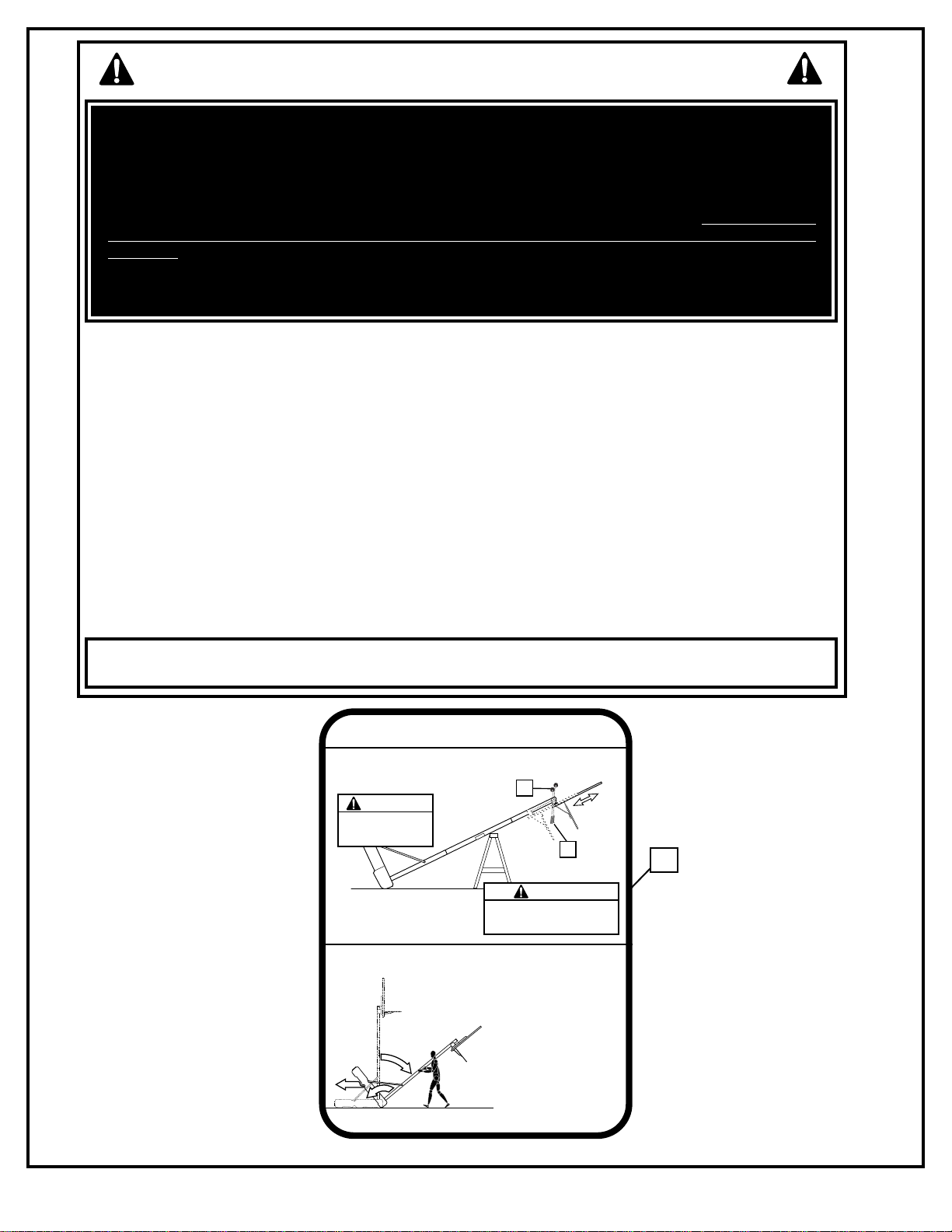
HEIGHT ADJUSTMENT
Rest unit on support table. Remove adjustment knobs (A)
and carriage bolts (B) to extend or retract backboard and rim.
Height adjustment from 7
1/2' to 10'.
A
WARNING
Backboard
may rotate during
height adjustment.
B
WARNING
Do not adjust height of system
in upright position. System must
be in down position to adjust
MOVING SYSTEM
1. While holding pole, rotate
basketball system forward
until wheels engage with
ground.
2. Move basketball system to
desired location.
3. Carefully rotate basketball
1
2
3
system upright.
4. Reattach ground restraint and
check system for stability.
200439 11/00
Page 4
4
P/N 211984A 04/03
For more information on assembly, placement, proper
use and maintenance, visit The American Basketball
Council website at http://www.smarthoops.com.
IMPORTANT!
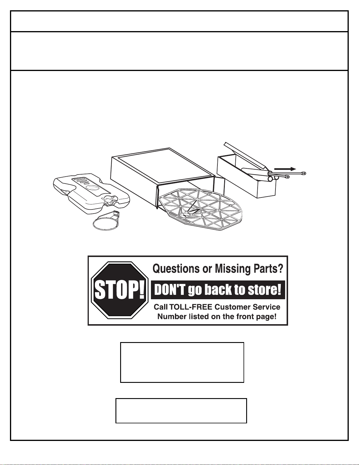
Remove all contents from boxes.
Be sure to check inside pole sections;
hardware and additional parts are packed inside.
NOTICE TO ASSEMBLERS
ALL Huffy Sports Basketball Systems, including those used for DISPLAYS, MUST be assembled
and ballasted with sand or water according to instructions. Failure to follow instructions could
result in SERIOUS INJURY. It is NOT acceptable to devise a makeshift weight system.
WARRANTY CARD:
Please remember to complete your product
registration form either on-line at:
www.huffysports.com/warrantycard or
mail-in the enclosed postcard.
Page 5
04/03 P/N 211984A
5
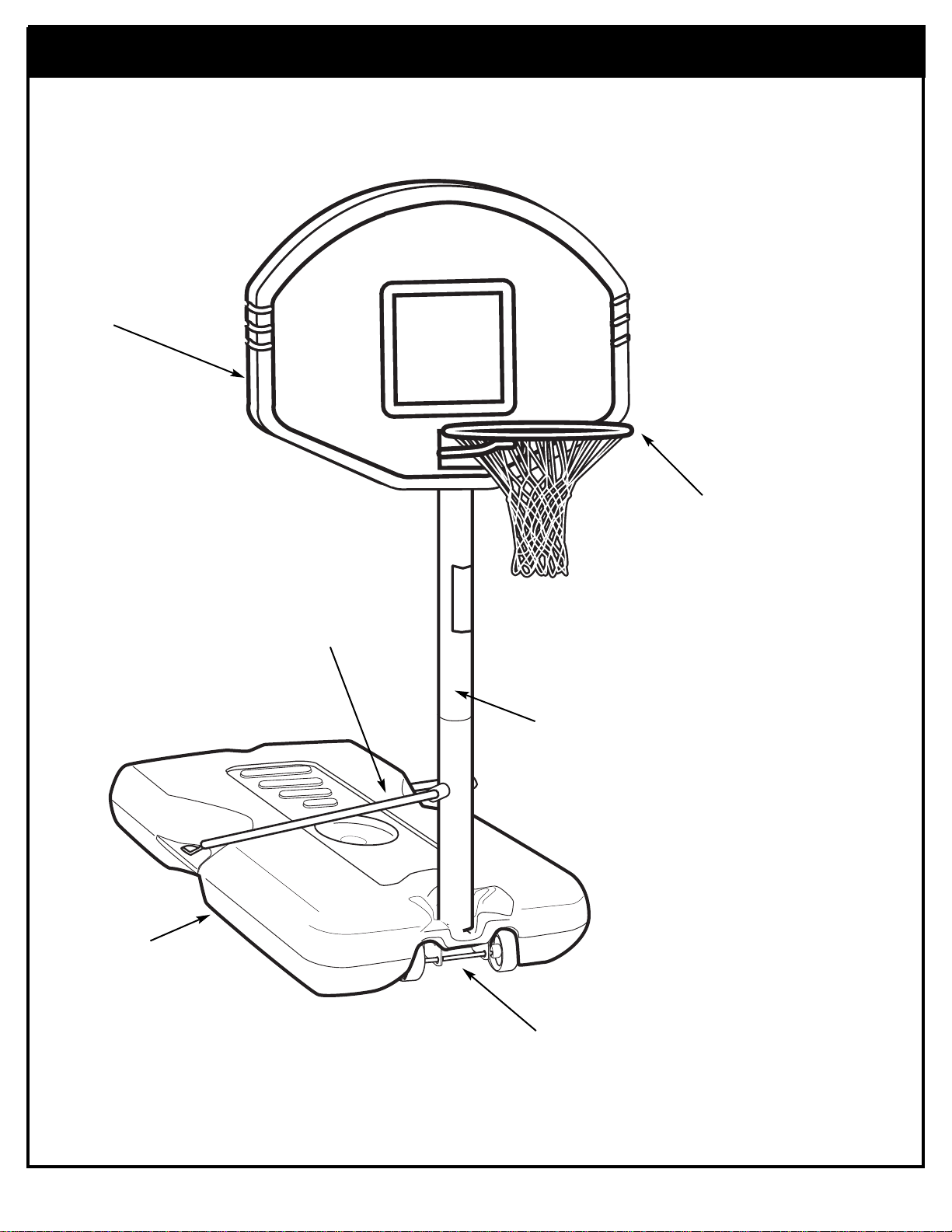
Get to know the basic parts of your basketball system.....
STRUTS
BACKBOARD
FRONT
RIM
WHEEL
CARRIAGE
ASSEMBLY
BASE
POLE
Page 6
6
P/N 211984A 04/03
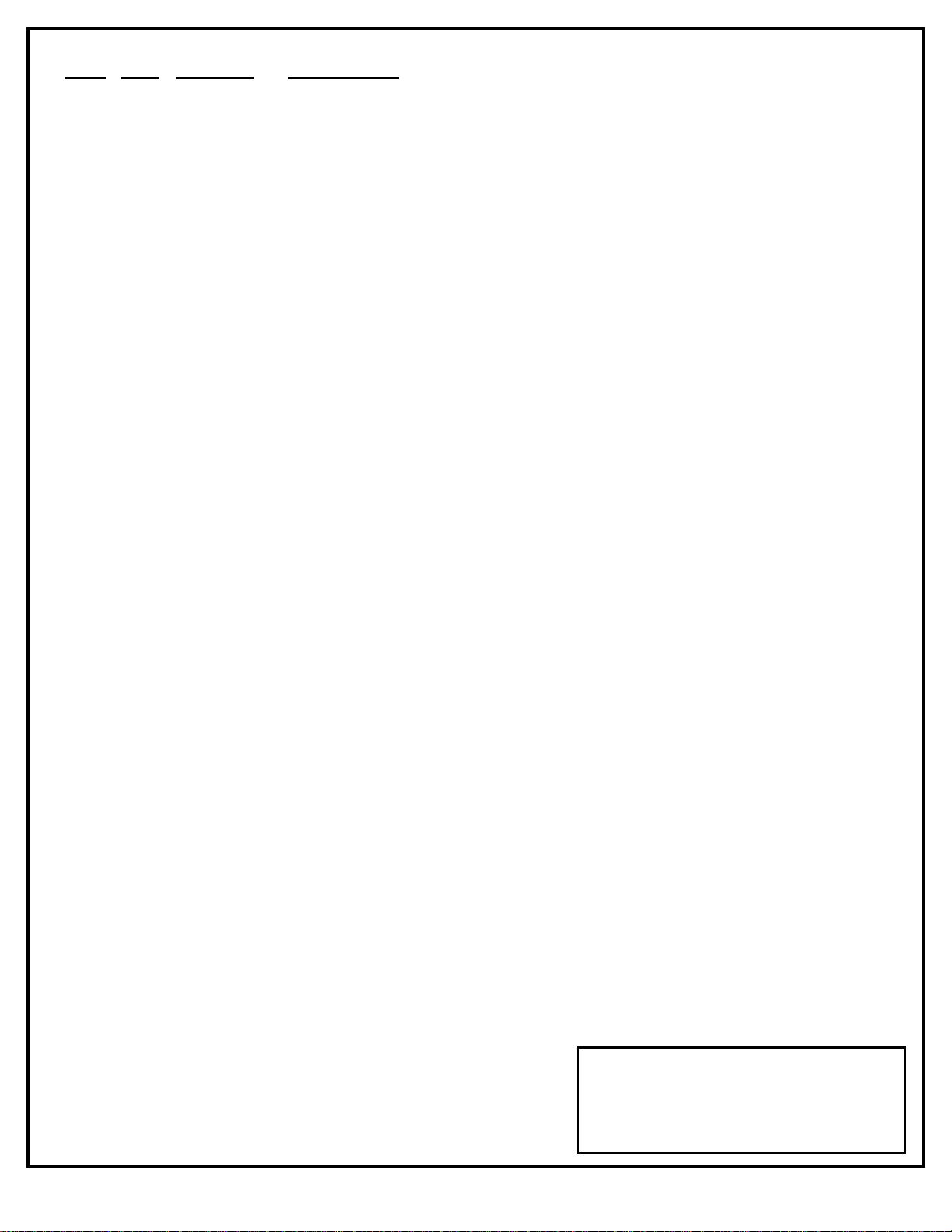
PARTS LIST - (See Hardware Identifier)
Item
Qty. Part No. Description
1 1 206740 Tank (White)
2 1 200628 11.75 Long Axle Rod
3 2 226401 Wheel
4 1 900220 Top Pole Section (White)
5 1 201190 Cap (White)
6 1 986102 Bottom Pole Section (White)
7 1 202822 Eyebolt, 3/8-16 x 3-3/4 Long
8 1 202820 Rod, 3/8 O.D. x 4-3/4 Long
9 1 200627 Bracket Wheel Carriage
10 1 203063 Lock Nut, Nylon Insert, 3/8-16
11 1 201625 Bolt, Hex Head, Yellow Dichromate, 5/16-18 x 3.60" Long
12 6 203218 Washer, 5/16 Flat
13 2 986206 Tank Strut (White)
14 1 203220 Lock Nut, 5/16-18
15 1 200439 Label, Height Adjustment and Moving
16 2 203156 Bolt, Hex Head, 5/16-18 x 1 Long
17 6 203100 Nut, Hex Flange 5/16-18
18 1 Rim
19 12* 201219 Clip, Net Holder Smart Clip
20 2 900207 Backboard Mounting Bracket
21 4 203309 Washer, 1 O.D.
22 4 203113 Bolt, Hex Flange, 5/16-18 x 2-1/2 Long
23 2 203231 Bolt, Carriage 5/16-18 x 3-1/2 Long
24 2 203435 Knob, Plastic, 1-3/4 Diameter
25 1 Net
26 1 201568 Tie Down Strap
27 1 203124 Tie Down Stake
28 1 201189 Base Plug
29 2 201651 Spacer, Plastic
* YOU MAY HAVE EXTRA PARTS WITH THIS MODEL.
WARRANTY CARD:
Please remember to complete your product
registration form either on-line at:
www.huffysports.com/warrantycard or
mail-in the enclosed postcard.
Page 7
04/03 P/N 211984A
7
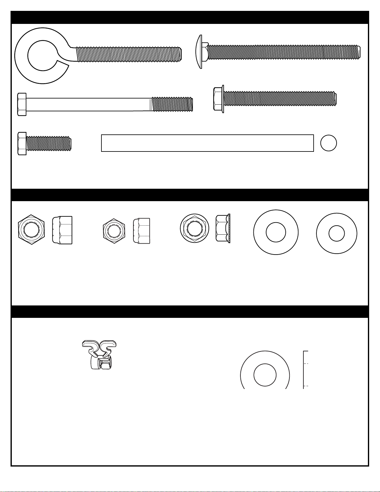
HARDWARE IDENTIFIER (BOLTS & STEEL RODS)
HARDWARE IDENTIFIER (NUTS & WASHERS)
HARDWARE IDENTIFIER (PLASTIC CLIPS & SPACERS)
Item #14 (1)
Item #12 (6)
Item #10 (1)
Item #19 (12)*
Item #16 (2)
Item #17 (6)
Item #21 (4)
Item #22 (4)
Item #7 (1)
Item #11 (1)
Item #8 (1)
Item #29 (2)
Item #23 (2)
Page 8
8
P/N 211984A 04/03
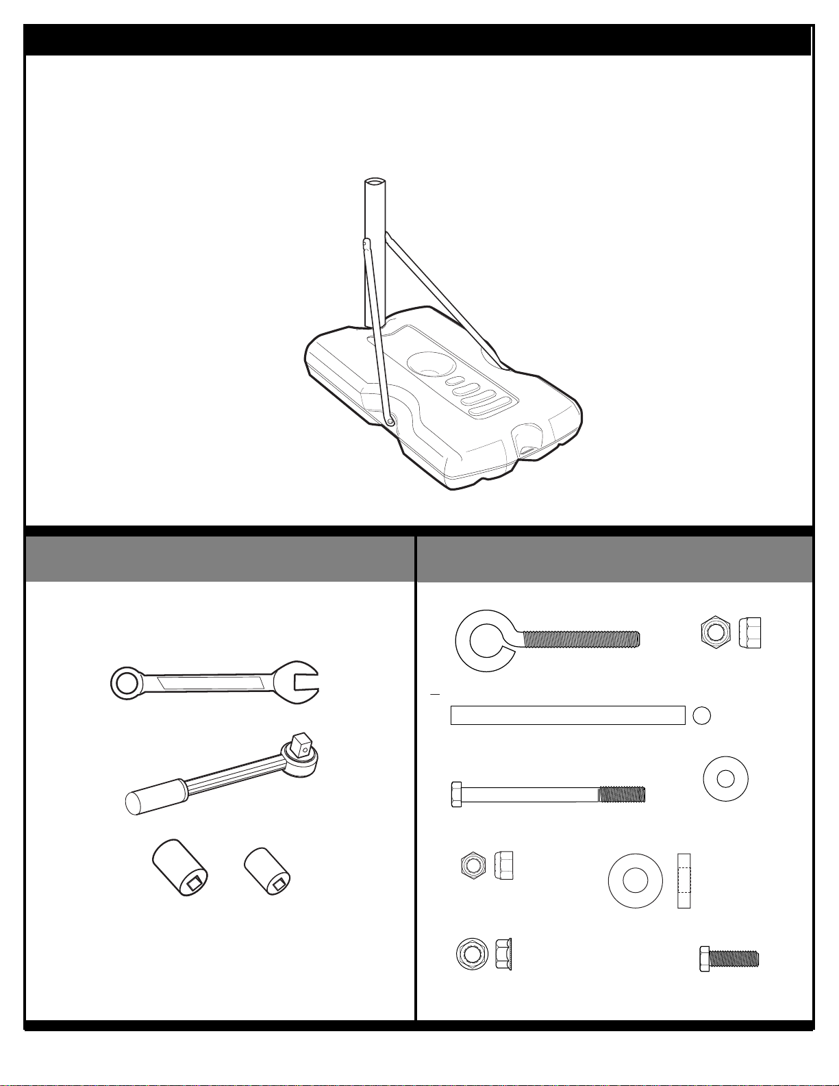
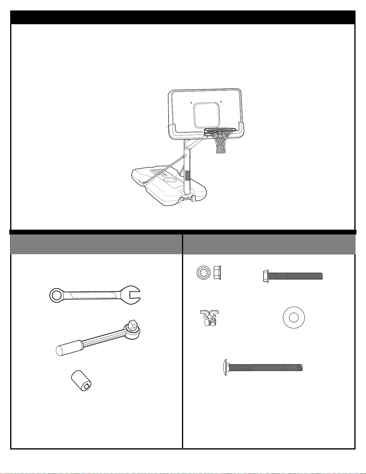
TOOLS REQUIRED FOR THIS SECTION
HARDWARE USED IN THIS SECTION
(not actual size)
SECTION A: ASSEMBLE THE BASE
9/16” and 1/2”
9/16” and 1/2”
AND/OR
This is what your system will look like
when you’ve finished this section:
Item #14 (1)
Item #12 (6)
Item #10 (1)
Item #16 (2)
Item #17 (6)
Item #7 (1)
Item #11 (1)
Item #8 (1)
Item #29 (2)
Page 9
04/03 P/N 211984A
9
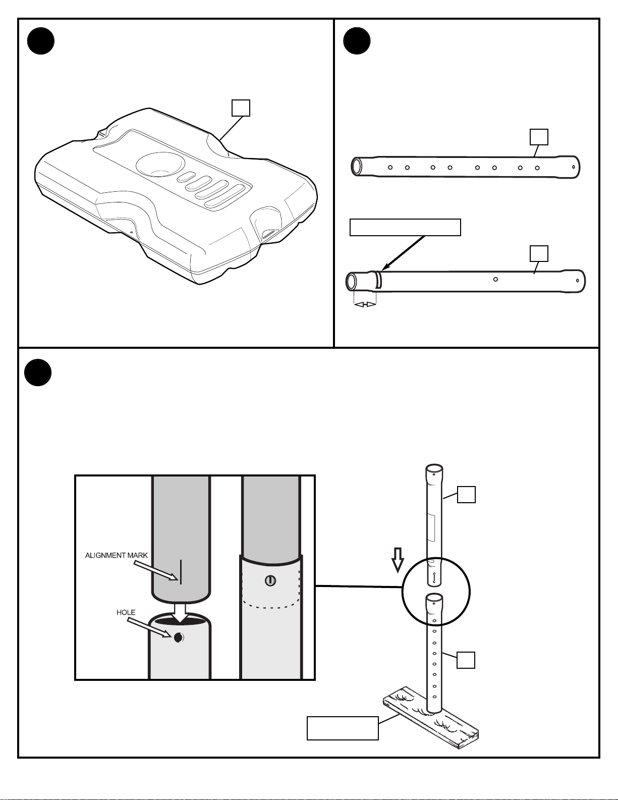
1.
1
Remove contents from tank
4
6
TOP
BOTTOM
5”
(13 cm)
2.
Correctly identify each pole
section and mark indicated
distance from ends with tape
as shown.
TAPE (Not Supplied)
3.
WOOD SCRAP
IMPORTANT! Center the alignment slot of bottom pole section (6) in the
lower hole of top pole section (4) as shown. While maintaining alignment,
bounce top section of pole (4) and bottom section (6) together as shown until
they no longer move toward taped reference mark.
NOTE: Pole sections should have a 3-1/2" (9 cm) minimum overlap.
6
4
Page 10
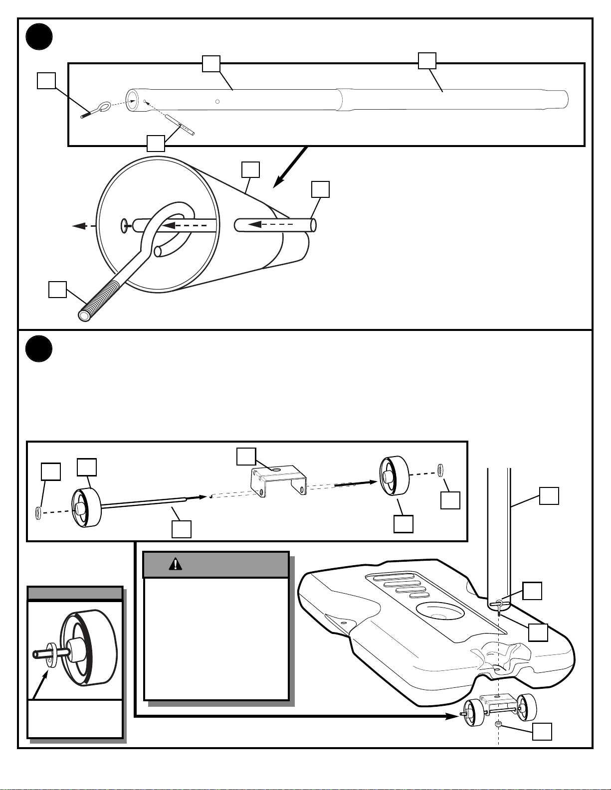
10
P/N 211984A 04/03
2.
Install rod (5) through holes in bottom pole section (4) and eyebolt (6).
7
8
6
8
7
4
6
10
6
8
7
3.
2
29
29
3
3
9
Install wheel axle (2) through wheel carriage (9). Install wheels (3) onto wheel
axle (2) with spacers (29) as shown. Insert pole assembly into tank assembly
as shown. Secure bottom pole (6) to tank and wheel bracket as shown, a
deep socket is recommended. IMPORTANT! DO NOT OVER TIGHTEN.
TWO PEOPLE
REQUIRED FOR THIS
PROCEDURE. FAILURE
TO FOLLOW THIS
WARNING COULD
RESULT IN SERIOUS
INJURY AND/OR
PROPERTY
DAMAGE.
WARNING!
THE SPACER (29) WILL
FIT LOOSELY UNTIL
SECURED INTO THE
CAVITY OF THE BASE.
IMPORTANT!:
Page 11
04/03 P/N 211984A
11
11
13
1
14
13
12
12
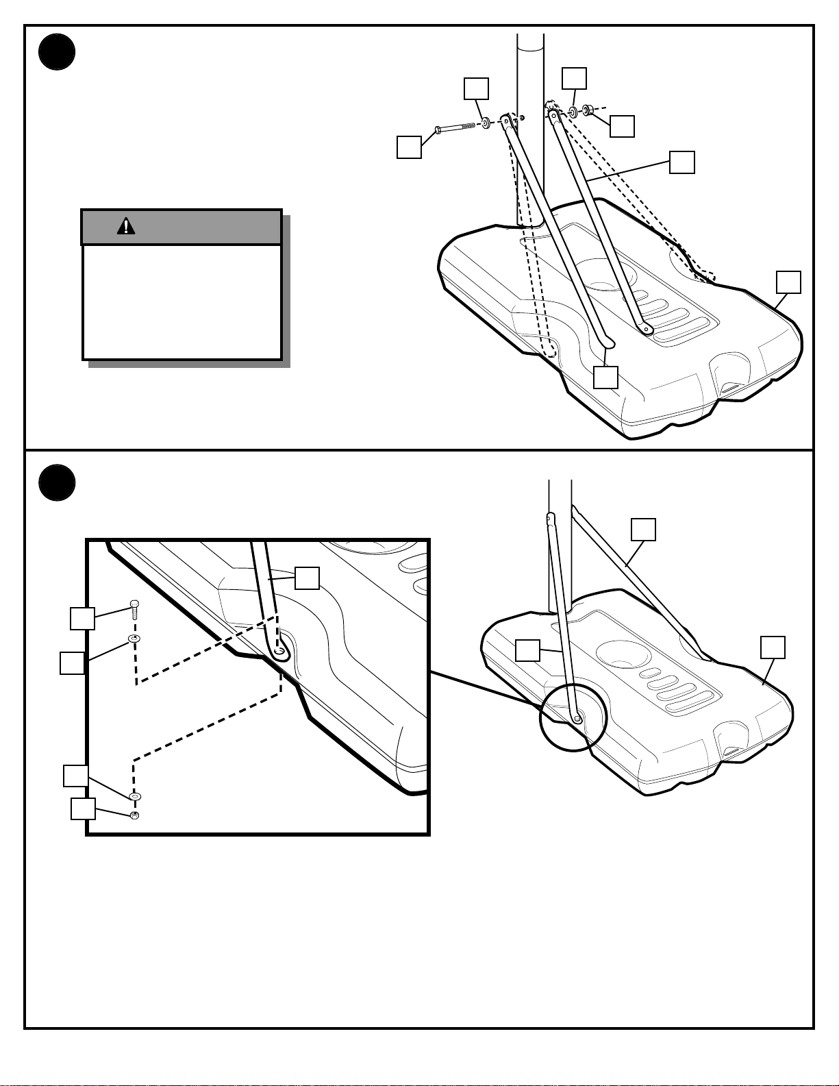
4.
Secure tank struts (13) to pole.
Rotate non-secured ends of tank
struts (13) outward to mounting
holes in tank as shown.
5.
13
13
1
Secure non-secured ends of tank struts (13) to
tank as shown. Repeat for opposite side.
13
17
12
12
16
TIGHTEN BOLT (9) IN
LOCK NUT (12) UNTIL
FLUSH (EVEN) WITH
LOCK NUT’S OUTER
EDGE.
WARNING!
Page 12
12
P/N 211984A 04/03
TOOLS REQUIRED FOR THIS SECTION
HARDWARE USED IN THIS SECTION
SECTION B: ASSEMBLE THE BACKBOARD
1/2”
1/2”
OR
This is what your system will look like
when you’ve finished this section:
Item #17 (6)
Item #19 (12)*
Item #21 (4)
Item #22 (4)
Item #23 (2)
Page 13
04/03 P/N 211984A
13
21
22
22
18
20
17
17
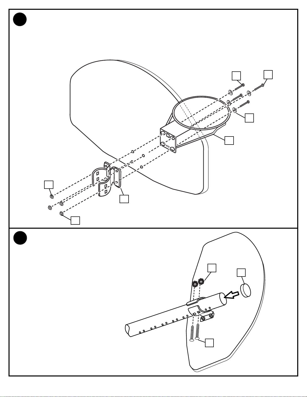
Mount brackets (20) and rim (18) to backboard and finger tighten as shown.
NOTE: Final adjustments will be made in Step 9.
IMPORTANT! For spring loaded rim assembly, refer to instructions
included with rim hardware.
6.
5
24
23
9.
While still in the horizontal position,
carefully slide backboard components onto
pole. Secure hardware at desired position
as shown and tighten all hardware
completely at this time.
Page 14
14
P/N 211984A 04/03
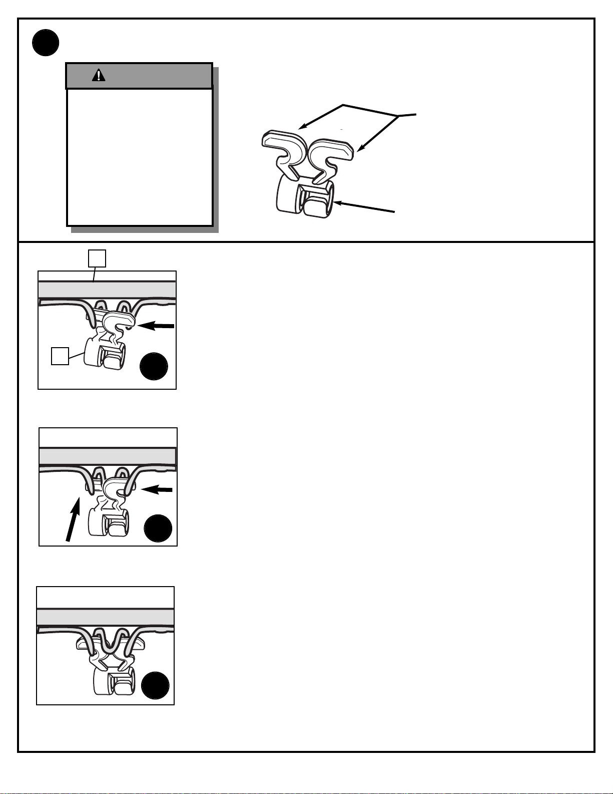
8.
Install clips.
CLIP “ARM”
CLIP “BODY”
Insert one “arm” of clip into ram as shown. Twist “body” of clip
slightly so that second “arm” slides over the top of the first “arm”
as shown.
Push in direction indicated by arrows.
Push second “arm” back and into ram as shown.
Twist “body” of clip slightly again to spread “arms” of clip.
Clip “arms” must be flat and touching edge to edge as shown,
not overlapping.
AA
BB
CC
18
19
USE OF THIS PRODUCT
WITHOUT PROPER
INSTALLATION OF
SMART CLIPS, OR WHEN
ALL SMART CLIPS ARE
NOT PRESENT COULD
RESULT IN BODILY
HARM. BE SURE TO
FOLLOW DIRECTIONS
CAREFULLY.
WARNING!
Page 15
04/03 P/N 211984A
15
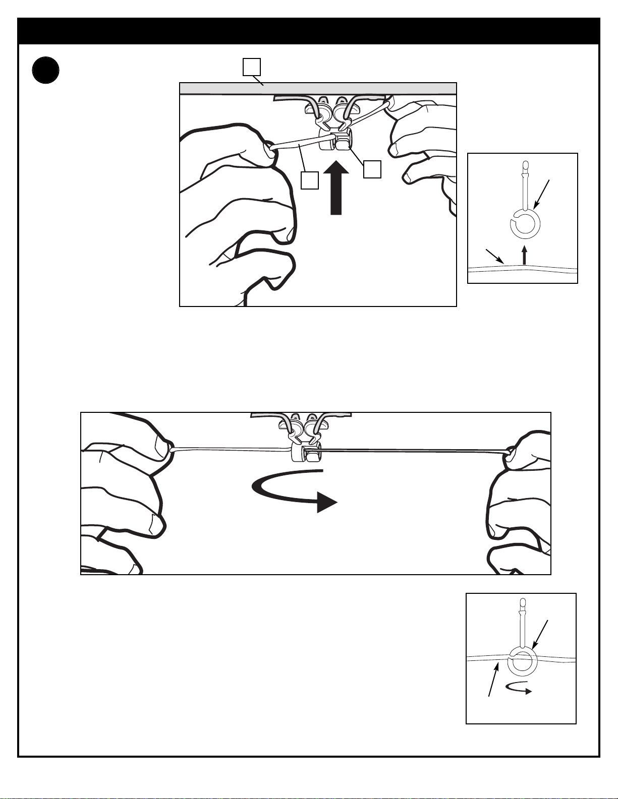
Insert net into bottom of clip as shown.
SIDE VIEW
Twist net until it snaps into position.
Net must be centered through clip.
NET
NETCLIP
SIDE VIEW
NET
NETCLIP
NET INSTALLATION
9.
18
19
25
Page 16
16
P/N 211984A 04/03
1.
28
26
27
26
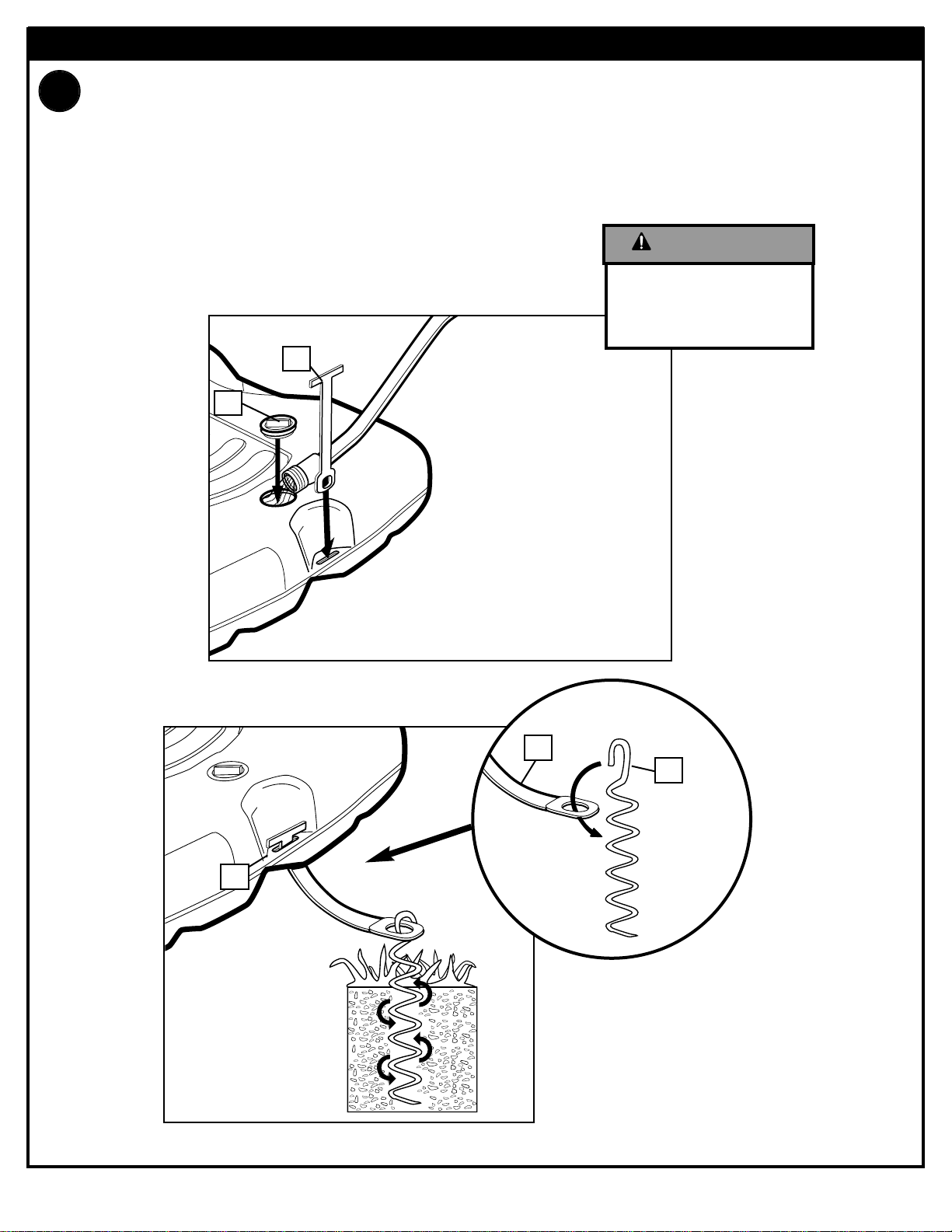
Place assembled unit to desired location. Fill tank with water (30 gallons (114
liters)) or sand (360 lb. (163 kg)) and snap tank cap (28) in place.
Insert T-strap (26) through slot on back of base as shown. Secure unit to
ground by twisting tie down stake (27) into ground and hooking T-strap (26)
onto tie down stake (27).
SECTION C: SECURING THE SYSTEM
26
Add two gallons (7.6
liters) of non-toxic
antifreeze in subfreezing climates.
CAUTION!
Page 17
04/03 P/N 211984A
17
1.
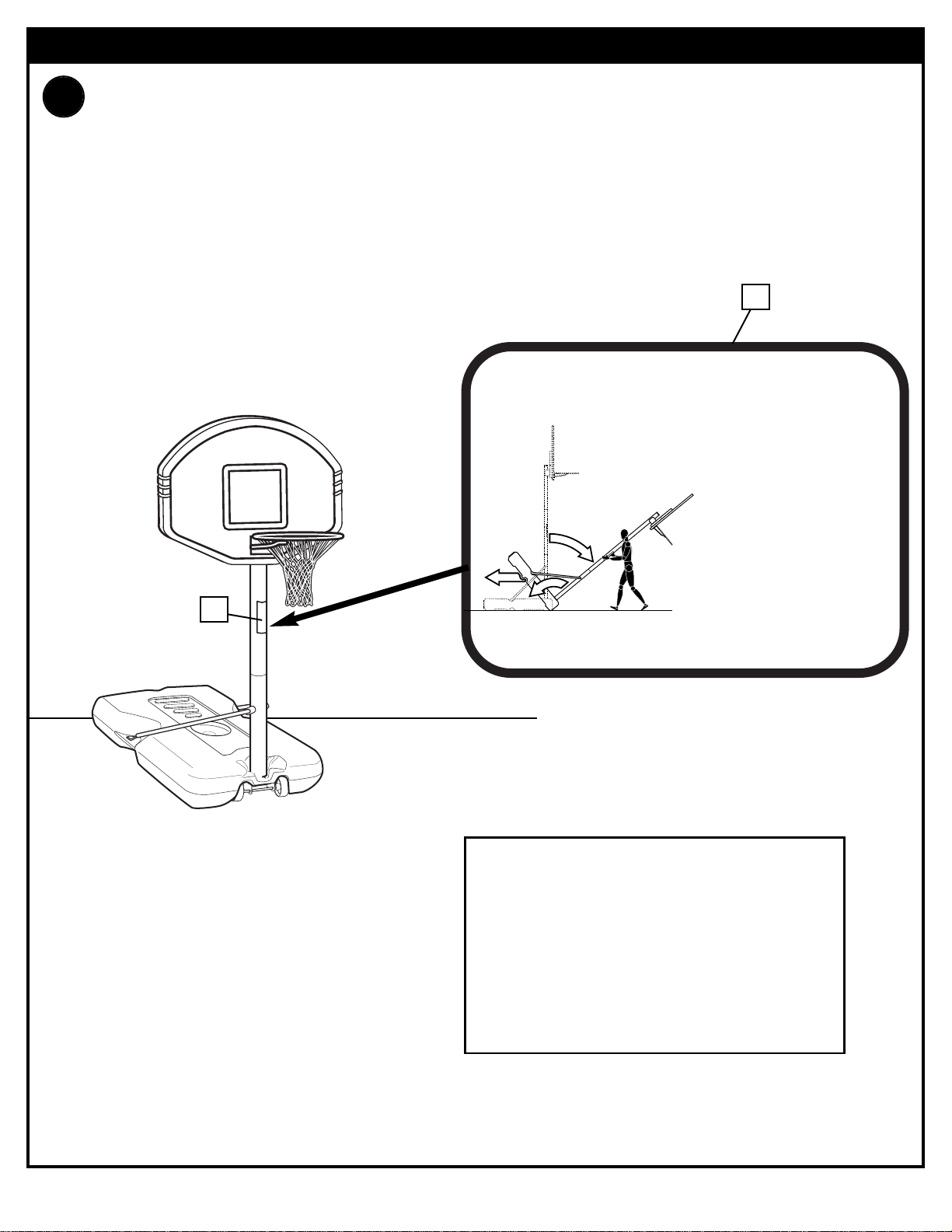
SECTION E: APPLY HEIGHT AND MOVING LABEL
Apply Height and Moving label on pole as shown.
15
201261 3/99
1
3
2
MOVING SYSTEM
1. While holding pole, rotate
basketball system forward
until wheels engage with
ground.
2. Move basketball system to
desired location.
3. Carefully rotate basketball
system upright.
4. Reattach ground restraint and
check system for stability.
15
WARNING: IF YOUR SYSTEM IS EQUIPPED WITH
AN ACRYLIC BACKBOARD, EXAMINE
BACKBOARD FOR ANY DAMAGE THAT MAY
HAVE OCCURRED DURING SHIPMENT. CRACKS
IN THE BACKBOARD COULD RESULT IN SUDDEN
BREAKAGE. IF BACKBOARD IS DAMAGED IN
ANY WAY PRIOR TO OR AFTER ASSEMBLY, CALL
TOLL-FREE NUMBER FOR FREE REPLACEMENT:
U.S. 1-800-558-5234; CANADA: 1-800-284-8339;
http://www.huffysports.com
 Loading...