

Page 1
1
5/99 P/N 211387
printed on recycled paper
Customer Service Center
N53 W24700 South Corporate Circle
Sussex, WI 53089
U.S.A.
A Huffy Company
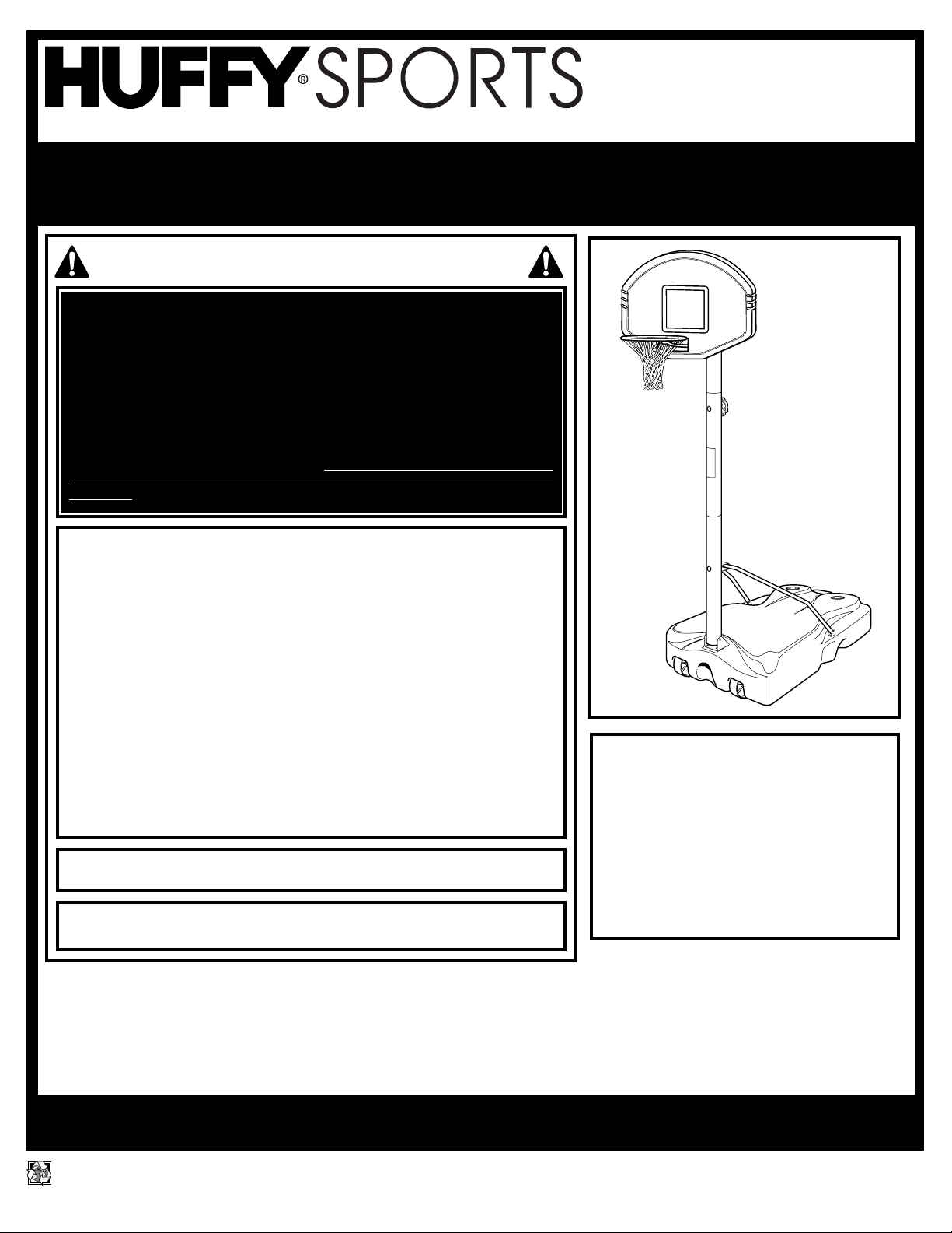
Portable Basketball System
Owners Manual
Toll-Free Customer Service Number for U.S: 1-800-558-5234 Canada Only: 1-800-284-8339
Internet Address: http://www.huffysports.com
In U.S. and Canada only: Have questions...don’t go back to the store!
We appreciate your purchasing one of our many fine products. We are sure that you will be very satisfied with your selection. Although
great care and effort have been taken, occasionally problems may occur. To ensure prompt and correct handling of any problems, or to
answer any questions, please contact our Toll-Free Customer Service Number listed below. Service will be quicker if you have your
Model Number (found on carton) and assembly instructions ready when calling. PLEASE WRITE YOUR MODEL NUMBER IN
THE SPACE PROVIDED ABOVE.
SAFETY INSTRUCTIONS
Most injuries are caused by misuse and/or not following instructions.
Use caution when using this system.
• If using a ladder during assembly, use extreme caution.
• Two (2) people are recommended for this operation.
• Check base regularly for leakage. Slow leaks could cause system to tip over
unexpectedly.
• Seat the pole sections properly (if applicable). Failure to do so could allow the pole
sections to separate during play and/or transport of the system.
• Climate, corrosion or misuse could result in system failure.
• If technical assistance is required, contact the manufacturer.
• Minimum operational height is 6'6" (1.98 m) to the bottom of backboard.
• This equipment is intended for home recreational use only and NOT
excessive competitive play.
• Read and understand the warning label affixed to pole. Label is shown on page 2.
• The life of your basketball pole depends on many conditions. The climate,
placement of the pole, the location of the pole, exposure to corrosives such as
pesticides, herbicides or salts are all important.
• If technical assistance is required, contact Huffy Sports.
• Adult supervision is recommended when adjusting height.
FAILURE TO FOLLOW THESE SAFETY INSTRUCTIONS MAY RESULT IN
SERIOUS INJURY, PROPERTY DAMAGE AND WILL VOID WARRANTY.
Owner must ensure that all players know and follow these rules for safe
operation of the system.
To ensure safety, do not attempt to assemble this system without following the
instructions carefully. Proper and complete assembly, use and supervision is
essential for proper operation and to reduce the risk of accident or injury. A high
probability of serious injury exists if this system is not installed, maintained, and
operated properly. Check entire box and inside all packing material for parts
and/or additional instructional material. Before beginning assembly, read the
instructions and identify parts using the hardware identifier and parts list in this
document.
For more information on assembly, placement, proper use and maintenance, visit
The American Basketball Council website at http://www.smarthoops.com.
WRITE IN YOUR MODEL NUMBER:___________
REQUIRED TOOLS AND
MATERIALS:
• Two People
• Wood Board (Scrap)
• Tape Measure
• Step Ladder 8 ft. (2.4 m)
• Tape
• Water or Sand 360 lb.
(163 kg)
• Hammer
• Wrench: 1/2”
• Support Table
Page 2
2
P/N 211387 5/99
printed on recycled paper
1
3
2
40
WARNING
FAILURE TO FOLLOW THESE WARNINGS MAY RESULT
IN SERIOUS INJURY AND/OR PROPERTY DAMAGE.
Owner must ensure that all players know and follow
these rules for safe operation of the system.
• DO NOT HANG on the rim or any part of the system
including backboard, support braces or net.
• During play, especially when performing dunk type
activities, keep player's face away from the backboard, rim
and net. Serious injury could occur if teeth/face come in
contact with backboard, rim or net.
• Do not slide, climb, shake or play on base and/or pole.
• After assembly is complete, fill system completely with
water or sand and stake to the ground. Never leave system
in an upright position without filling base with weight, as
system may tip over causing injuries.
• When adjusting height or moving system, keep hands and
fingers away from moving parts.
• Do not allow children to move or adjust system.
• During play, do not wear jewelry (rings, watches, necklaces,
etc.). Objects may entangle in net.
• Surface beneath the base must be smooth and free of
gravel or other sharp objects. Punctures cause leakage and
could cause system to tip over.
• Keep organic material away from pole base. Grass, litter,
etc. could cause corrosion and/or deterioration.
• Check pole system for signs of corrosion (rust, pitting,
chipping) and repaint with exterior enamel paint. If rust has
penetrated through the steel anywhere, replace pole
immediately.
• Check system before each use for proper ballast, loose
hardware, excessive wear and signs corrosion and repair
before use.
•
Check system before each use for instability.
• Do not use system during windy and/or severe weather
conditions; system may tip over. Place system in the
storage position and/or in an area protected from the wind
and free from personal property and/or overhead wires.
• Never play on damaged equipment.
• See instruction manual for proper installation and
maintenance.
• When moving system, use caution to keep mechanism from
shifting.
• Keep pole top covered with cap at all times.
• Do not allow water in tank to freeze. During sub-freezing
weather add non-toxic antifreeze, sand or empty tank
completely and store. (Do not use salt.)
• Use extreme caution if placing system on sloped surface.
System may tip over more easily.
201241 2/99
In the U.S.:1-800-558-5234 and Canada: 1-800-284-8339
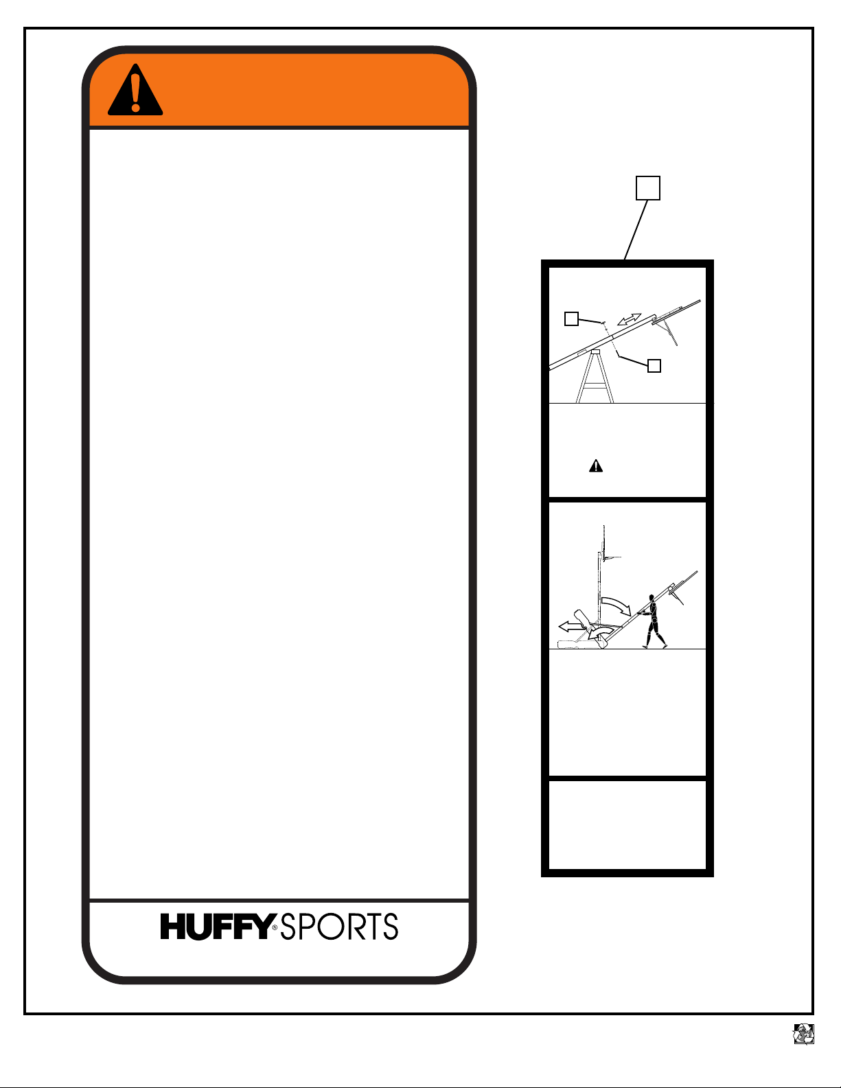
HEIGHT ADJUSTMENT
for all Telescoping Pole Systems
A
B
Rest unit on support table. Remove
adjustment knob (A) and carriage
bolt (B) to extend or retract pole.
Pole adjusts from 7
1/2’ to 10’.
WARNING
Backboard and top pole may
rotate during height adjustment.
MOVING SYSTEM
1. While holding pole, rotate
basketball system forward until
wheels engage with ground.
2. Move basketball system to
desired location.
3. Carefully rotate basketball
system upright.
4. Reattach ground restraint and
check system for stability.
This unit also folds down for
convenient storage. See
owner’s manual for fold-up
procedure.
201259 3/99
Page 3
3
5/99 P/N 211387
printed on recycled paper
5
6
8
7
9
5
6
5
8
13
6
IMPORTANT! WRITE DOWN MODEL NUMBER FROM BOX ON PAGE 1 OF THIS OWNERS MANUAL
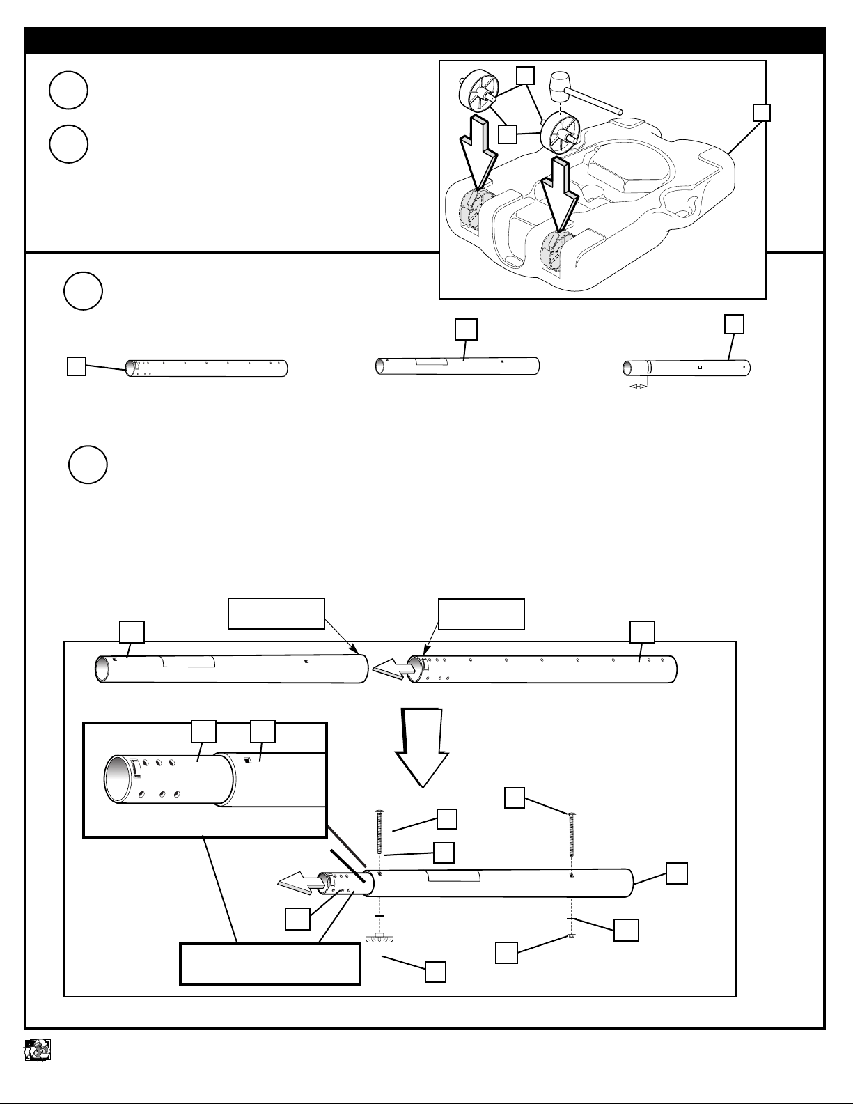
1.
Remove contents from tank (1).
Turn tank (1) bottom side up. Insert axle rod (2)
through wheel (3), as shown. Secure wheel assembly
to tank by tapping wheel assembly downward with
hammer. It will snap into position. Repeat for opposite
side, then carefully turn tank over.
2.
1
2
3
7
Correctly identify each pole section and
mark indicated distance from end of
bottom pole section (4) with tape as shown.
3.
6
4
5
TOP
BOTTOM
MIDDLE
5”
(13 cm)
Slide top of upper pole section (5) through bottom of middle pole section (6). Secure top
and middle pole sections together in both locations as shown, using carriage bolts (7),
washers (8), adjustment knob (9), and flange nut (13).
IMPORTANT! This step MUST be completed before going on to step 5.
4.
“Top of upper
pole section”
“Bottom of middle
pole section”
NOTE: Top pole section will slide
through middle pole section.
Page 4
4
P/N 211387 5/99
printed on recycled paper
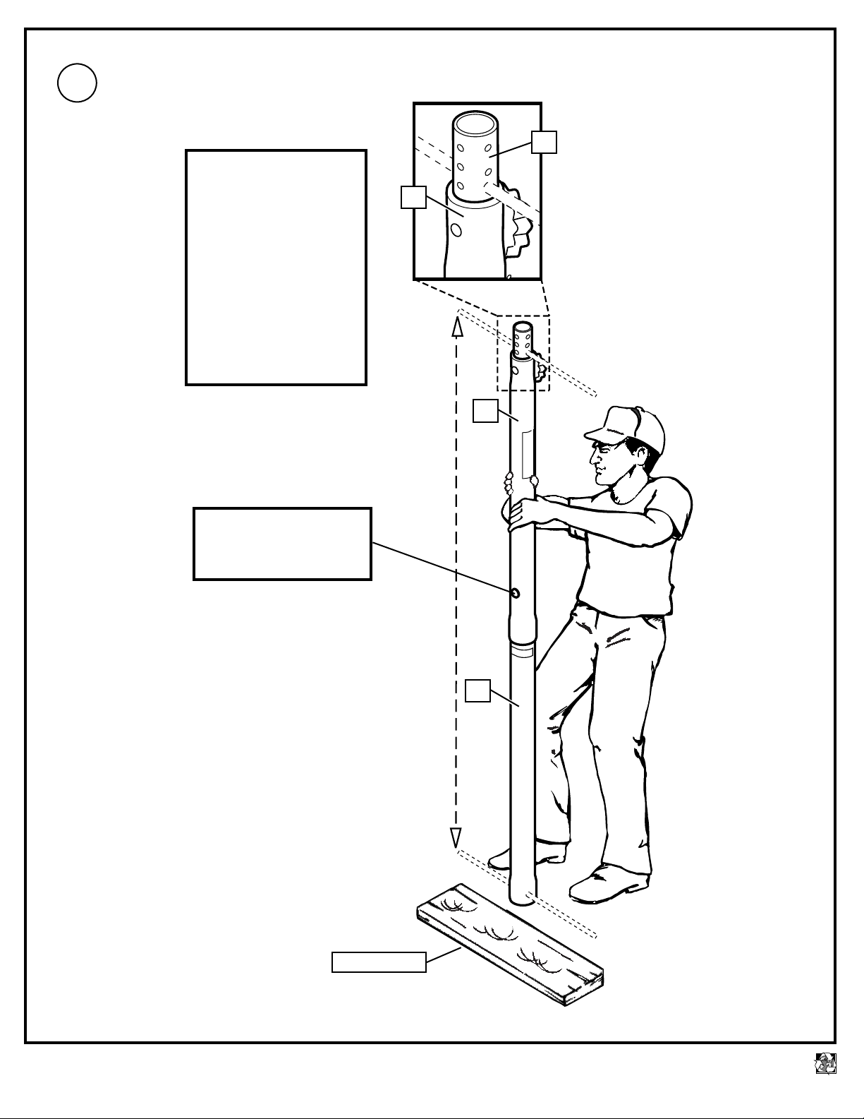
5
WOOD SCRAP
4
6
Add bottom pole section (4) to assembly as
shown and bounce until completely tight.
5.
*
IMPORTANT!
Holes in top and bottom pole
sections MUST align to correctly
position elevator system.
Continue to check alignment
while assembling pole sections.
*
Row of 3 holes on top pole
section must be parallel with
adjustment knob.
Once assembled, pole
sections can NOT be
separated!
POLES MUST OVERLAP
3-1/2” (9 CM) MINIMUM.
NOTE: Discard this carriage
bolt immediately after completing
this step. DO NOT discard flange
nut and washer.
6
Page 5

5
5/99 P/N 211387
printed on recycled paper
6.
Attach base pole bracket (10) and base strut
brackets (11) to base (1) as shown below.
10
Attach struts (14) as shown above.
7.
LLAS
SAND
AST
ND
9.
Place tank (1) in desired location. Fill tank (1)
with water (30 gallons (114 liters)) or sand (360
lb. (163 kg)). Snap tank cap (18) in place.
12
15
10
13
14
11
1
11
18
1
13
13
8
8
12
12
13
8
IMPORTANT!
Add two gallons (7.6 liters) of
NON-TOXIC ANTIFREEZE
in sub-freezing climates.
15
Attach pole strut bracket (16) to
struts (14) as shown at left.
8.
13
13
17
16
14
14
SAND
BA
BALLAST
SA
BALL
Page 6

6
P/N 211387 5/99
printed on recycled paper
Attach lower halves of backboard
brackets (23) to swivel bracket (21).
NOTE: Keep hardware loose until
after alignment in step 16.
13.
23
12
13
13
12
21
Attach upper pole mounting bracket (20) to swivel
bracket (21) and fully tighten.
12.
21
22
8
12
20
Attach pole assembly to pole bracket (10) as
shown. NOTE: Keep unnecessary pressure off
of the pole assembly when in this position. Two
people recommended for this step.
11.
8
13
19
10
10.
Rest pole assembly on FILLED tank.
WARNING
KEEP UNNECESSARY
PRESSURE OFF OF THE
POLE ASSEMBLY WHEN IN
THIS POSITION. TWO
PEOPLE RECOMMENDED
FOR THIS STEP.
Page 7

7
5/99 P/N 211387
printed on recycled paper
NOTE: Two people recommended for this
procedure. Attach bracket assembly to top pole
section (5). Secure hardware as shown and
tighten completely. Install pole cap (25).
14.
24
13
7
25
5
8
Attach back bracket (26) to backboard and
backboard brackets (23) as shown and finger
tighten. NOTE: Do NOT tighten completely. Final
adjustments will be made in step 24.
16.
23
23
13
27
27
27
13
Bend upper halves of backboard brackets (23) to
line up with mounting holes on backboard as shown.
15.
26
PLAY
POSITION
STORAGE
POSITION
Page 8

8
P/N 211387 5/99
printed on recycled paper
NOTE: Stretching net
up then pulling side to
side will help snap net
under center hook.
IMPORTANT! MAKE
SURE NET IS HELD BY
ALL THREE HOOKS ON
THE NET CLIP.
Install net (35).
20.
Install net clips (34) on rim
(28).
The two outer hooks on net clip must face
towards inside of goal rim. Insert larger hole
in net clip onto rim stud, push down on net
clip, then slide net clip right, locking or
snapping securely into position (clips must
"snap" into place to insure a secure fit).
NOTE: Net clips should not slide with
ease. It is very important that the net clips
are in the locked position before going on
to next step
USE OF THIS PRODUCT WITHOUT
PROPER INSTALLATION OF NET
CLIPS, OR WHEN ALL NET CLIPS
ARE NOT PRESENT COULD
RESULT IN BODILY HARM.
BE SURE TO FOLLOW
DIRECTIONS CAREFULLY.
WARNING
The Quick Clip™ rapid release net system lets the net pull away from the rim. This reduces
the risk of player injury or property damage. However, improper installation or a ball
making contact at an odd angle may disengage the net clip from the goal rim. Usually, the
clip is reinstalled with little or no problem. We hope that you agree this inconvenience is
minor when compared to the safety of the players.
Quick Clip: US Patent No. 5,792,010/5,795,253
19.
INSIDE VIEW
35
28
Assemble rim (28) to back bracket (26) as shown.
17.
29
22
8
28
30
31
26
To keep rim components from shifting during installation
procedure, install knob set (32 and 33) through spacer
(31) in the upper set of holes in rim bracket as shown.
18.
32
33
31
OUTSIDE VIEW
28
34
Page 9

9
5/99 P/N 211387
printed on recycled paper
NOTE: Two people recommended for this procedure. Level backboard
and rim adjust hardware from step 13 and 16. Tighten completely.
Regulation
rim height
is 10 feet
(3.05 m).
24.
Apply height adjustment label (40) to front of pole as shown.
25.
10 feet
(3.05 m)
23.
Carefully upright pole and backboard assembly. Secure
strut assembly (14) to bottom pole section (4) as shown.
38
40
14
9
8
4
21.
Attach nylon tie down stake rope (36)
to tank (1) as shown.
1
36
Secure unit to ground using nylon
rope (36) and tie down stake (37).
37
36
22.
TWO PERSON MINIMUM REQUIRED
FOR THIS PROCEDURE. NOT
FOLLOWING RECOMMENDATION MAY
RESULT IN SERIOUS BODILY INJURY
AND/OR PROPERTY DAMAGE.
WARNING
Page 10

10
P/N 211387 5/99
printed on recycled paper
TO PLACE IN THE STORAGE POSITION
Lower backboard and rim down to the
lowest position (7
1/2
’ (2.29 m)).
Remove adjustment knob (9), washer
(8), and carriage bolt (7). Carefully
rotate pole downward towards
ground.
DO NOT STAND BEHIND
SYSTEM WHEN PREPARING
FOR STORAGE.
WARNING
1.
2.
3.
Secure pole assembly to tank (1) with carriage
bolt (7), washer (8), and adjustment knob (9).
Remove adjustment knob (24) from swivel
bracket (21) and carefully rotate backboard
assembly 180º.
7
8
9
1
Secure backboard assembly in storage position
with adjustment knob set (24 and 8) as shown.
4.
24
8
HEIGHT ADJUSTMENT
SUPPORT TABLE
7
Rest unit on support table.
Remove adjustment knob (9),
carriage bolt (7), and washer (8)
to extend or retract pole. Pole
adjusts from 71/2’ to 10’.
Re-Insert Adjustment set
(7, 8, 9) When pole is at
desired height.
9
1.
8
BACKBOARD AND TOP POLE
MAY ROTATE DURING
HEIGHT ADJUSTMENT.
WARNING
PLAY
POSITION
STORAGE
POSITION
Page 11

11
5/99 P/N 211387
printed on recycled paper
Secure screw hook (39) into wall, approximately
50” (127 cm) up from floor as shown.
IMPORTANT! It is necessary to install screw hook
into a wall stud.
Remove tie down stake (37) from ground and
detach rope (36). Rotate system up onto the front
wheels and roll toward the wall. Secure system with
rope (36) on screw hook (39).
39
36
8.
7.
36
39
6.
Carefully rotate system up on its side to remove
water or sand from tank.
Remove knob set (32, 31, and 33) from the rim assembly
and re-insert knob set into top locking position.
5.
32
33
31
50"
(127 cm)
Page 12

12
P/N 211387 5/99
printed on recycled paper
PARTS LIST
Item Qty. Part No. Description
1 1 206903 Tank
2 2 206327 Wheel Axle
3 2 226401 Wheel
4 1 908492 Bottom Pole Section
5 1 906643 Top Pole Section
6 1 906642 Middle Pole Section with Label
7 4 203231 Bolt, Carriage, 5/16-18 x 3-1/2 Long
8 12 203218 Washer, 5/16 Flat
9 2 203435 Knob, Plastic, 3 Diameter
10 1 206911 Bracket, Base Pole
11 2 206910 Bracket, Base Strut, 2 x 1.2
12 11 203223 Bolt, Carriage, 5/16-18 x 1
13 23 203100 Nut, Hex Flange, 5/16-18
14 2 906918 Tank Strut
15 2 203084 Bolt, Carriage, 5/16-18 x 1-3/4
16 1 906914 Bracket, Pole Strut
17 2 203217 Bolt, Carriage, 5/16-18 x 1-1/2
18 2 203617 Tank Cap, 1 3/4
19 1 206110 Bolt, Carriage, 5/16-18 x 3-3/4
20 1 206916 Bracket, Upper Pole Mounting
Item
Qty. Part No. Description
21 1 206912 Bracket, Swivel, 3-3/4 x 2-1/4
22 2 203099 Locknut, 5/16-18, Nylon Insert
23 2 906633 Bracket, Backboard
24 1 206629 Knob, Threaded, 5/16-18
25 1 206641 Pole Cap, 2-3/4
26 1 906625 Bracket, Back
27 6 203157 Bolt, Carriage, 5/16-18 x 2-1/4
28 1 900931 Rim
29 1 206004 Bolt, Carriage, 5/16-18 x 6
30 1 206005 Stop Washer
31 2 202790 Spacer, 5-1/4 Long
32 1 206639 Knob, Threaded, 3/8-16 x 5-3/4
33 1 203429 Knob, Plastic, 1" diameter, 3/8 nut
34 12* 200121 Clips
35 1 204281 Net
36 1 204444 Rope Nylon, Double Loop, 1’ x 24"
37 1 203124 Tie down Stake
38 1 206909 Bolt, Carriage, 5/16-18 x 5-1/2
39 1 203449 Hook Screw
40 1 201259 Label, Height Adjustment and Moving
* You may have extra parts with this model.
HARDWARE IDENTIFIER
Item #15 (2)
Item #12 (11)
Item #13 (23)
Item #19 (1)
Item #8 (11)
* YOU MAY HAVE EXTRA PARTS WITH THIS MODEL.
Item #17 (2)
Item #7 (4)
Item #22 (1)
Page 13

13
5/99 P/N 211387
printed on recycled paper
HARDWARE IDENTIFIER (continued)
Item #38 (1)
Item #39 (1)
Item #29 (1)
Item #30 (1)
Item #31 (2)
Item #27 (6)
Item #34 (12)*
 Loading...