

Page 1
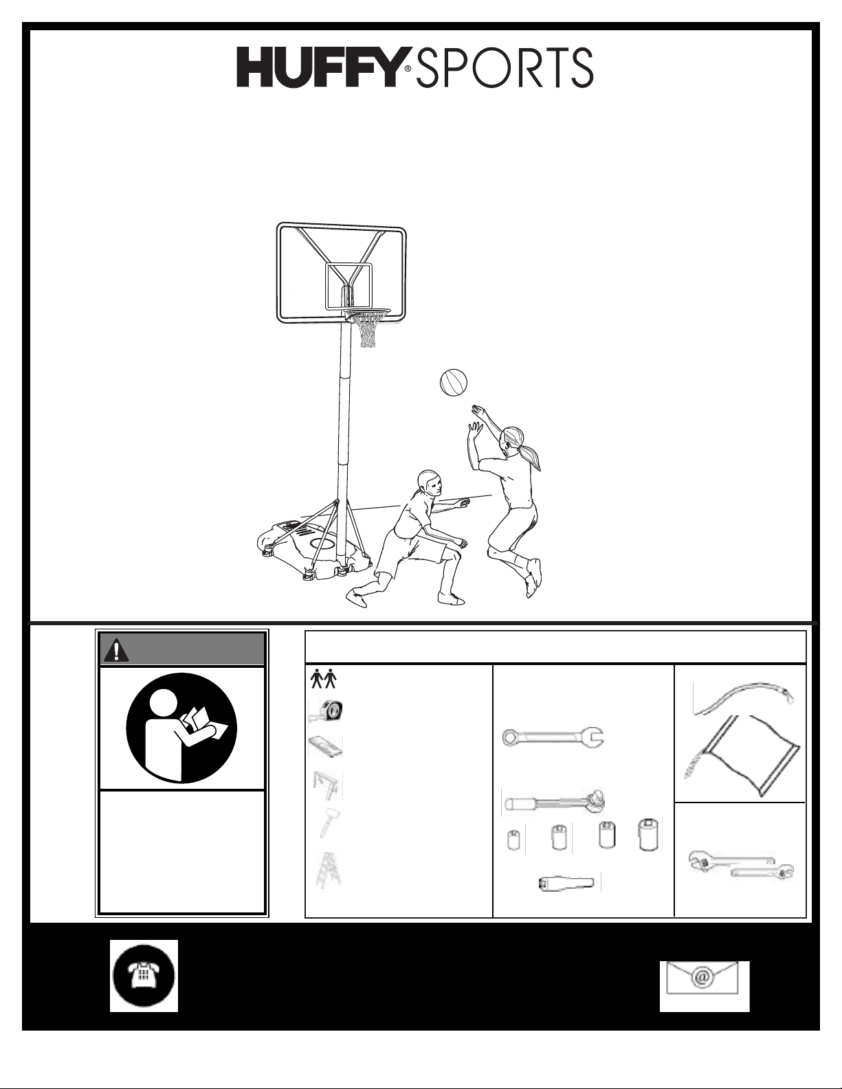
Portable Basketball System
Owners Manual
Customer Service Center
• N53 W24700 South Corporate Circle • Sussex, WI 53089 • U.S.A.
WARNING!
READ AND UNDERSTAND
OPERATOR'S MANUAL
BEFORE USING THIS UNIT.
FAILURE TO FOLLOW
OPERATING INSTRUCTIONS
COULD RESULT IN INJURY
OR DAMAGE TO
PROPERTY.
© COPYRIGHT 2004 by HUFFY SPORTS
REQUIRED TOOLS AND MATERIALS:
• 2 People
• Tape Measure
• Wood Board (scrap)
• Sawhorse or
Support Table
• Hammer
• Step Ladder 8 ft. (2.4m)
Toll-Free Customer Service Number for U.S: 1-800-558-5234,
For Canada: 1-800-284-8339,
For Europe: 00 800 555 85234 (Sweden: 009 555 85234),
For Australia: 1-800-333 061
Internet Address: http://www.huffysports.com
1
• (2 each) Wrenches and/or
Socket Wrenches and
Sockets (Deep-Well Sockets
are Recommended).
7/16" 1/2" 9/16" 3/4"
AND/OR
7/16" 1/2" 9/16" 3/4"
• Extension is Required.
• Garden Hose or
Sand
SAND
SAND
(360 lb.)
(360 lb.)
(163 kg)
(163 kg)
• Optional: Large &
Small Adjustable
Wrenches
05/04 P/N 211472
Page 2
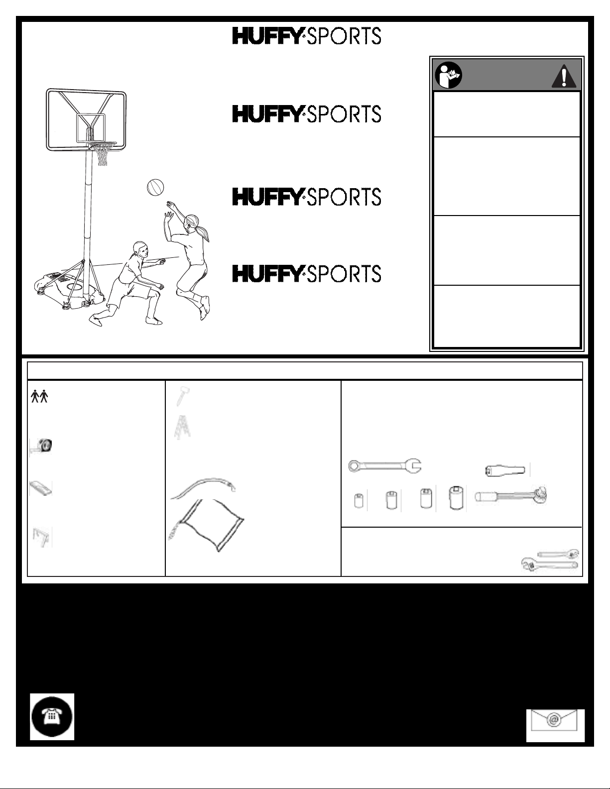
Système portable
Manuel d'utilisation
o N53 W24700 South Corporate Circle o Sussex, WI 53089 o É.-U.
Service clientèle
Tragbares System
Gebrauchsanleitung
• N53 W24700 South Corporate Circle • Sussex, WI 53089 • U.S.A.
Kundendienstzentrale
Sistema portátil
Manual del propietario
o N53 W24700 South Corporate Circle o Sussex, WI 53089 o EE.UU.
Centro de Servicio al Cliente
Tabellone e cerchio
Manuale di istruzioni
o N53 W24700 South Corporate Circle o Sussex, WI 53089 o U.S.A.
Centro assistenza alla clientela
F
RANÇAIS
E
SPAÑOL
DEUTSCH
I
TALIANO
AVERTISSEMENT !
WARNUNG!
¡ADVERTENCIA!
LISEZ LE MODE D'EMPLOI
A
VANT D'UTILISER CE SYSTÈME
SOUS PEINE D'ENCOURIR DES BLESSURES
O
U DES DÉGÂTS MATÉRIELS.
D
AS BENUTZERHANDBUCH VOR
GEBRAUCH DIESES PRODUKTS
SORGFÄLTIG DURCHLESEN.
EIN MISSACHTEN DIESER
BETRIEBSANLEITUNG KANN
VERLETZUNGEN ODER
SACHSCHÄDEN ZUR FOLGE
HABEN.
LEA Y ENTIENDA EL MANUAL DEL
OPERADOR ANTES DE USAR ESTA UNIDAD.
SI NO SE SIGUEN LAS
INSTRUCCIONES DE OPERACIÓN SE
PODRÍA OCASIONAR UNA LESIÓN O DAÑOS
A
LA PROPIEDAD.OR DAMAGE TO
PROPERTY.
P
RIMA DI USARE IL SISTEMA, LEGGERE IL
MANUALE DI ISTRUZIONI FINO A
COMPRENDERLO A FONDO.
L'INOSSERVANZA DELLE ISTRUZIONI
POTREBBE TRADURSI IN GRAVI INFORTUNI
E/O DANNI ALLE COSE.
REQUIRED TOOLS AND MATERIALS:
o
Deux personnes
o
Zwei Personen
o
Dos personas
o
(2) persone.
o Mètre
o Maßband
o Cinta de medir
o Metro
o Planche en bois (chute)
o Holzstück
o Tabla de madera (un trozo)
o Tavoletta di legno
o Banc de sciage ou table d'appui
o Sägebock oderStütztisch
o Caballete o mesa de apoyo
o Cavalletto di supporto o tavolo
di appoggio
o Marteau
o Hammer
o Martillo
o Martello
o Échelle de 2,4 m
o Stufenleiter 2,4m (8 Fuß)
o Escalera de mano de 8 pies (2.4m)
o Scala a libro da 2,4m (8')
o Tuyau d'arrosage ou sable
o Gartenschlauch oder Sand
o Manguera de jardín o arena
o Canna da giardino o sabbia
SAND
SAND
(360 lb.)
(360 lb.)
(163 kg)
(163 kg)
o SABLE (163 kg)
o SAND 163 kg (360 lbs)
o ARENA (360 libras) (163 kg)
o SABBIA (163 kg) (360 libbre)
Numéro sans frais du service clientèle (États-Unis) : 1-800-558-5234 ; Canada : 1-800-284-8339 ; Europe : 00 800 555 85234
(Suède : 009 555 85234), Pour l'Australie : 1-800-333 061 - Site Internet : http://www.huffysports.com
Gebührenfreie Kundendienstnummer für Anrufer in den USA: 1-800-558-5234 Für Anrufer in Kanada: 1-800-284-8339 Für
Anrufer in Europa: 00 800 555 85234 (Schweden: 009 555 85234) Für Australien: 1-800-333.061 - Internet-Adresse:
http://www.huffysports.com
o (2) clés et/ou clés à douilles et douilles (douilles longues recommandées).
Extension obligatoire.
o (je 2) Schraubenschlüssel und/oder Steckschlüssel und Einsätze (tiefe
Einsätze empfohlen). Verlängerung ist erforderlich.
o (2 de cada una) llaves de tuercas y/o llaves de tuercas de boca tubular y
casquillos (se recomiendan casquillos profundos). Se requiere una
extensión.
o Due (2) chiavi e/o chiavi a bussole e bussole (si consigliano bussole a
incasso profondo). È necessaria la prolunga.
7/16" 1/2" 9/16" 3/4"
o Facultatif : petites et grandes clés anglaises
o Optional: Große und kleine verstellbare Schraubenschlüssel
o Opcional: Llaves de tuercas ajustables grandes y pequeñas
o Facoltativamente: chiavi inglesi grande e piccola
Número telefónico gratuito de servicio al cliente en EE. UU.: 1-800-558-5234, para Canadá: 1-800-284-8339, para Europa: 00
800 555 85234 (Suecia: 009 555 85234), para Australia: 1-800-333 061 - Dirección en Internet: http://www.huffysports.com
Numero verde per chi chiama dagli U.S.A.: 1-800-558-5234, per il Canada: 1-800-284-8339,
per l'Europa: 00 800 555 85234 (per la Svezia: 009 555 85234), per l'Australia: 1-800-333 061.
Sito Web: http://www.huffysports.com
P/N 211472 05/04
2
Page 3
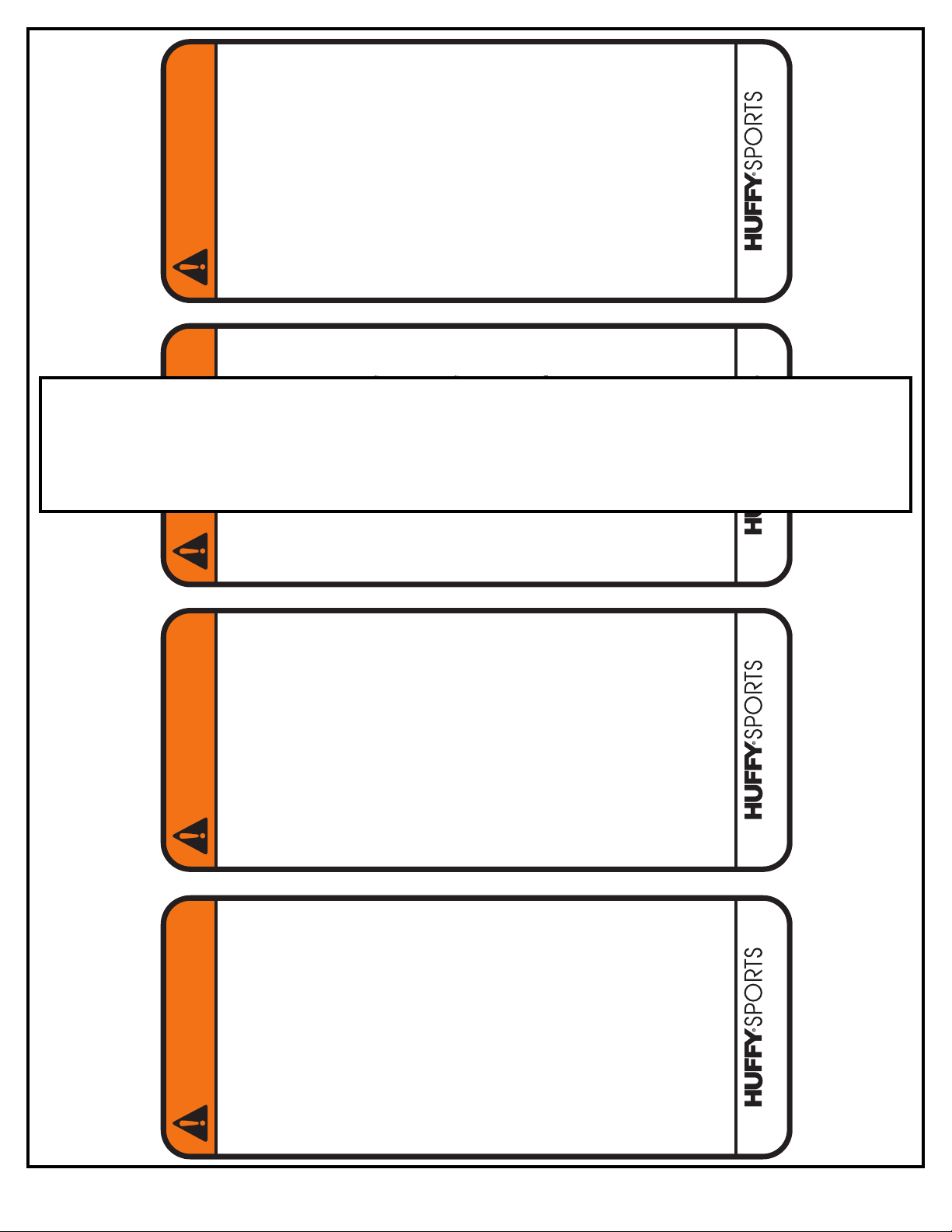
WARNING
FAILURE TOFOLLOW THESE WARNINGS MAY RESULT
IN SERIOUS INJURY AND/OR PROPERTY DAMAGE.
Owner must ensure that all players know and follow
these rules for safe operation of the system.
• DO NOT HANG on the rim or any part of the system
including backboard, support braces or net.
• During play, especially when performing dunk type
activities, keep player's face away from the backboard, rim
and net. Serious injury could occur if teeth/face come in
contact with backboard, rim or net.
• Do not slide, climb, shake or play on base and/or pole.
• After assembly is complete, fill system completely with
water or sand and stake to the ground. Never leave system
in an upright position without filling base with weight, as
system may tip over causing injuries.
• When adjusting height or moving system, keep hands and
fingers aw ay from moving parts.
• Do not allow children to move or adjust system.
• During play, do not wear jewelry (rings, watches, necklaces,
etc.). Objects may entangle in net.
• Surface beneath the base must be smooth and free of
gravel or other sharp objects. Punctures cause leakage and
could cause system to tip ov er.
• Keep organic material away from pole base. Grass, litter,
etc. could cause corrosion and/or deterioration.
• Check pole system for signs of corrosion (rust, pitting,
chipping) and repaint with exterior enamel paint. If rust has
penetrated through the steel anywhere, replace pole
immediately.
• Check system before each use for proper ballast, loose
hardware, ex c essive wear and signs corrosion and repair
before use .•Check system before each use fo r instability.
• Do not use system during windy and/or severe weather
conditions; system may tip over. Place system in the
storage position and/or in an area protected from the wind
and free from personal property and/or overhead wires.
• Never play on damaged equipment.
• See instruction manual for proper installation and
maintenance.
• When moving system, use caution to keep mechanism from
shifting.
• Keep pole top covered with cap at all times.
• Do not allow water in tank to freeze. During sub-freezing
weather add non-toxic antifreeze, sand or empty tank
completely and store. (Do not use salt.)
• Use extreme caution if placing system on sloped surface.
System may tip over more easily.
201241 2/99
In the U.S.:1-800-558-5234 and Canada: 1-800-284-8339
WARNING
FAILURE TO FOLLOW THESE WARNINGS MAY RESULT
IN SERIOUS INJURY AND/OR PROPERTY DAMAGE.
Owner must ensure that all players know and follow
these rules for safe operation of the system.
• DO NOT HANG on the rim or any part of the system
including backboard, support braces or net.
• During play, especially when performing dunk type
activities, keep player's face away from the backboard, rim
and net. Serious injury could occur if teeth/face come in
contact with backboard, rim or net.
• Do not slide, climb, shake or play on base and/or pole.
• After assembly is complete, fill system completely with
water or sand and stake to the ground. Never leave system
in an upright position without filling base with weight, as
system may tip over causing injuries.
• When adjusting height or moving system, keep hands and
fingers aw ay from moving parts.
• Do not allow children to move or adjust system.
• During play, do not wear jewelry (rings, watches, necklaces,
etc.). Objects may entangle in net.
• Surface beneath the base must be smooth and free of
gravel or other sharp objects. Punctures cause leakage and
could cause system to tip ov er.
• Keep organic material away from pole base. Grass, litter,
etc. could cause corrosion and/or deterioration.
• Check pole system for signs of corrosion (rust, pitting,
chipping) and repaint with exterior enamel paint. If rust has
penetrated through the steel anywhere, replace pole
immediately.
• Check system before each use for proper ballast, loose
hardware, ex c essive wear and signs corrosion and repair
before use .
•
Check system before each use fo r instability.
• Do not use system during windy and/or severe weather
conditions; system may tip over. Place system in the
storage position and/or in an area protected from the wind
and free from personal property and/or overhead wires.
• Never play on damaged equipment.
• See instruction manual for proper installation and
maintenance.
• When moving system, use caution to keep mechanism from
shifting.
• Keep pole top covered with cap at all times.
• Do not allow water in tank to freeze. During sub-freezing
weather add non-toxic antifreeze, sand or empty tank
completely and store. (Do not use salt.)
• Use extreme caution if placing system on sloped surface.
System may tip over more easily.
201241 2/99
In the U.S.:1-800-558-5234 and Canada: 1-800-284-8339
WARNING
FAILURE TO FOLLOW THESE WARNINGS MAY RESULT
IN SERIOUS INJURY AND/OR PROPERTY DAMAGE.
Owner must ensure that all players know and follow
these rules for safe operation of the system.
• DO NOT HANG on the rim or any part of the system
including backboard, support braces or net.
• During play, especially when performing dunk type
activities, keep player's face away from the backboard, rim
and net. Serious injury could occur if teeth/face come in
contact with backboard, rim or net.
• Do not slide, climb, shake or play on base and/or pole.
• After assembly is complete, fill system completely with
water or sand and stake to the ground. Never leave system
in an upright position without filling base with weight, as
system may tip over causing injuries.
• When adjusting height or moving system, keep hands and
fingers aw ay from moving parts.
• Do not allow children to move or adjust system.
• During play, do not wear jewelry (rings, watches, necklaces,
etc.). Objects may entangle in net.
• Surface beneath the base must be smooth and free of
gravel or other sharp objects. Punctures cause leakage and
could cause system to tip ov er.
• Keep organic material away from pole base. Grass, litter,
etc. could cause corrosion and/or deterioration.
• Check pole system for signs of corrosion (rust, pitting,
chipping) and repaint with exterior enamel paint. If rust has
penetrated through the steel anywhere, replace pole
immediately.
• Check system before each use for proper ballast, loose
hardware, ex c essive wear and signs corrosion and repair
before use .•Check system before each use fo r instability.
• Do not use system during windy and/or severe weather
conditions; system may tip over. Place system in the
storage position and/or in an area protected from the wind
and free from personal property and/or overhead wires.
• Never play on damaged equipment.
• See instruction manual for proper installation and
maintenance.
• When moving system, use caution to keep mechanism from
shifting.
• Keep pole top covered with cap at all times.
• Do not allow water in tank to freeze. During sub-freezing
weather add non-toxic antifreeze, sand or empty tank
completely and store. (Do not use salt.)
• Use extreme caution if placing system on sloped surface.
System may tip over more easily.
201241 2/99
In the U.S.:1-800-558-5234 and Canada: 1-800-284-8339
WARNING
FAILURE TO FOLLOW THESE WARNINGS MAY RESULT
IN SERIOUS INJURY AND/OR PROPERTY DAMAGE.
Owner must ensure that all players know and follow
these rules for safe operation of the system.
• DO NOT HANG on the rim or any part of the system
including backboard, support braces or net.
• During play, especially when performing dunk type
activities, keep player's face away from the backboard, rim
and net. Serious injury could occur if teeth/face come in
contact with backboard, rim or net.
• Do not slide, climb, shake or play on base and/or pole.
• After assembly is complete, fill system completely with
water or sand and stake to the ground. Never leave system
in an upright position without filling base with weight, as
system may tip over causing injuries.
• When adjusting height or moving system, keep hands and
fingers aw ay from moving parts.
• Do not allow children to move or adjust system.
• During play, do not wear jewelry (rings, watches, necklaces,
etc.). Objects may entangle in net.
• Surface beneath the base must be smooth and free of
gravel or other sharp objects. Punctures cause leakage and
could cause system to tip ov er.
• Keep organic material away from pole base. Grass, litter,
etc. could cause corrosion and/or deterioration.
• Check pole system for signs of corrosion (rust, pitting,
chipping) and repaint with exterior enamel paint. If rust has
penetrated through the steel anywhere, replace pole
immediately.
• Check system before each use for proper ballast, loose
hardware, ex c essive wear and signs corrosion and repair
before use .
•
Check system before each use fo r instability.
• Do not use system during windy and/or severe weather
conditions; system may tip over. Place system in the
storage position and/or in an area protected from the wind
and free from personal property and/or overhead wires.
• Never play on damaged equipment.
• See instruction manual for proper installation and
maintenance.
• When moving system, use caution to keep mechanism from
shifting.
• Keep pole top covered with cap at all times.
• Do not allow water in tank to freeze. During sub-freezing
weather add non-toxic antifreeze, sand or empty tank
completely and store. (Do not use salt.)
• Use extreme caution if placing system on sloped surface.
System may tip over more easily.
201241 2/99
In the U.S.:1-800-558-5234 and Canada: 1-800-284-8339
NEED TRANSL ATIONPUT IN
3
05/04 P/N 211472
Page 4
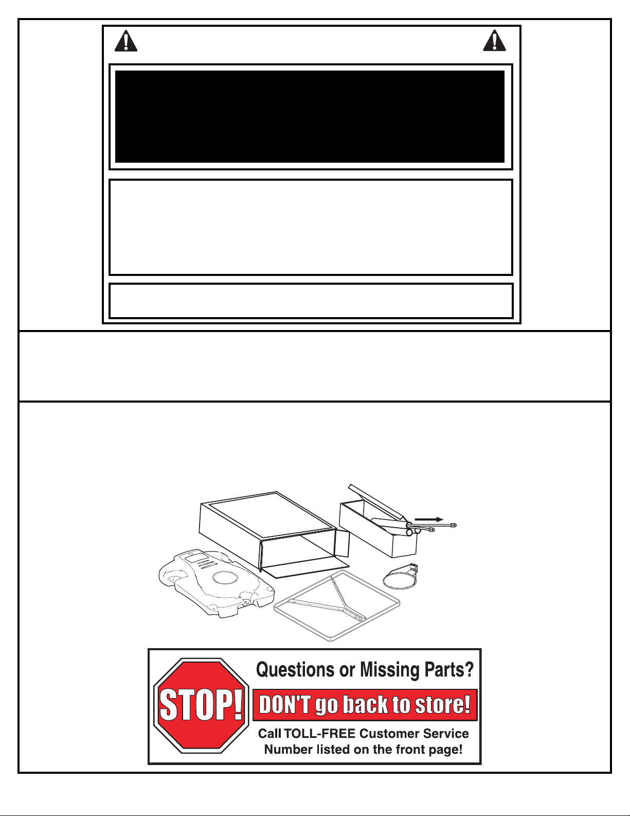
SAFETY INSTRUCTIONS
FAILURE TO FOLLOW THESE SAFETY INSTRUCTIONS MAY RESULT IN SERIOUS INJURY,
PROPERTY DAMAGE AND WILL VOID WARRANTY.
Owner must ensure that all players know and follow these rules for safe operation of the system.
To ensure safety, do not attempt to assemble this system without following the instructions carefully. Proper
and complete assembly, use and supervision is essential for proper operation and to reduce the risk of
accident or injury. A high probability of serious injury exists if this system is not installed, maintained, and
operated properly.
• If using a ladder during assembly, use extreme caution.
• Check base regularly for leakage. Slow leaks could cause the system to tip over
unexpectedly
• Seat the pole sections properly (if applicable). Failure to do so could allow the pole
sections to seperate during play and/or during transport of the system.
• Climate, corrosion or misuse could result in system failure.
• If technical assistance is required, contact Huffy Sports.
• Minimum operational height is 6’6” (1.98m) to the bottom of backboard.
Most injuries are caused by misuse and/or not following instructions.
Use caution when using this unit.
NOTICE TO ASSEMBLERS
ALL Huffy Sports basketball Systems, including those used for DISPLAYS, MUST be assembled
and ballasted with sand or water according to instructions. Failure to follow instructions could
result in SERIOUS INJURY. It is NOT acceptable to devise a makeshift weight system.
IMPORTANT!
Remove all contents from boxes.
Be sure to check inside pole sections,
hardware and additional parts are packed inside.
P/N 211472 05/04
4
Page 5
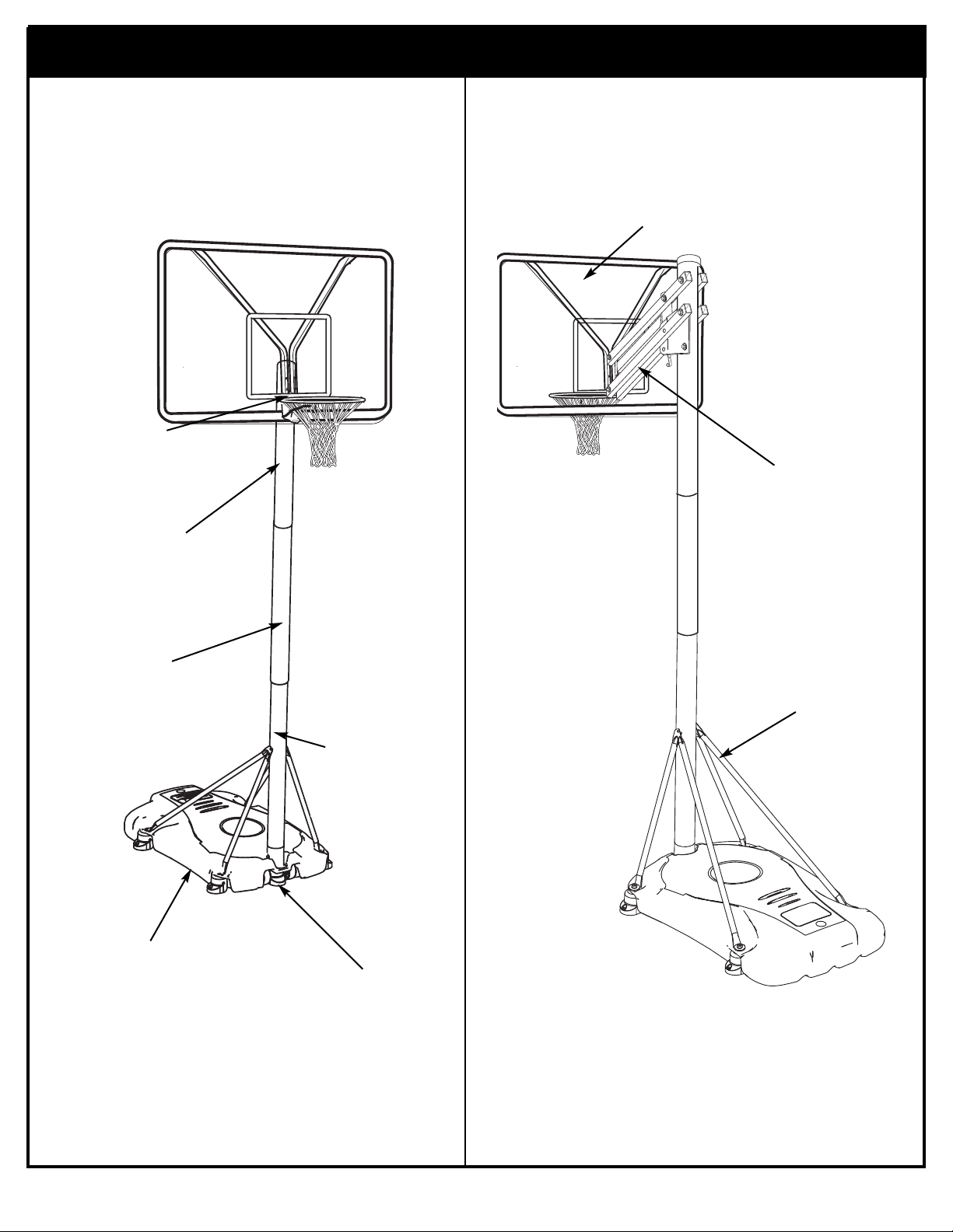
Get to know the basic parts of your basketball system.....
½
RIM
TOP POLE
FRONT
BACK
BACKBOARD
ELEVATOR
ASSEMBLY
MIDDLE POLE
BASE
STRUTS
BOTTOM
POLE
WHEEL
CARRIAGE
ASSEMBLY
5
05/04 P/N 211472
Page 6
PARTS LIST (See Hardware Identifier)
Qty. Part No. Description
Item
1 1 206647 Tank (Black)
2 1 200628 Wheel Axle
3 2 226401 Wheel
4 1 908136 Top Pole Section
5 1 908077 Middle Pole Section with Label
6 1 905840 Bottom Pole Section
7 1 202820 Rod, 3/8 O.D. x 4-3/4 Long
8 1 202822 Eye Bolt, 3/8 x 16 x 3-3/4 Long
9 5 202821 Disk, 2.75 O.D.
10 9 203063 Lock Nut, Nylon Insert, 3/8-16
11 1 202622 Bolt, Hex Head, 5/16-18 x 4-1/2
12 2 906411 Tank Strut, Short
13 2 900478 Tank Strut, Long
14 1 203220 Lock Nut, 5/16-18
15 1 201254 Label, Moving System
16 2 200874 Spacer, Steel .402 I.D. x .50 O.D. x 1.5 Long
17 8 203100 Nut, Hex Flange 5/16-18
18 1 900635 Rim
19 12* 201219 Clip, Net Holder
20 1 900416 Backboard Mounting Bracket
21 18 203309 Washer, 1 O.D.
22 4 206360 Bolt, Hex 3/8-16 x 2.65 Long
23
1 206273
Bolt, Hex, 1/2-13 X 4.5" Long
24 5 201382 Support Foot
25 1 Net
26
1 207103
Pole Cap
27 6 201651 Spacer, Wheel Axle
28 1 203617 Tank Cap
29
1 908139
Plate, Jack Support, Left
30 1 908137 Plate, Jack Support, Right
31 1 204085 Decal, Height Indication
32 5 206304 Bolt, Hex 1/2-13 X 6-5/16 Long
33 6 201642 Spacer, Plastic, .63" Long
34 4 908138 Elevator Tubes
35 7 206340 Lock-Nut, Nylon Insert, 1/2-13 for bolt #32
805231 Screw Jack
1
36
2 206249 Bolt, Hex 1/2-13 X 1.25" Long
37
2 201129 Spacer, .5"OD x 1.8 Long
38
39 1 206269 Spacer, .75" O.D., 4" Long
40 1 206234 Cover, Indicator
41 1 207103 Pole Cap
42
1
806259
Crank
WARRANTY CARD:
Please remember to complete your product
registration form either on-line at:
www.huffysports.com/warrantycard or mail-in
the enclosed postcard.
YOU MAY HAVE EXTRA PARTS WITH THIS MODEL.
*
P/N 211472 05/04
6
Page 7
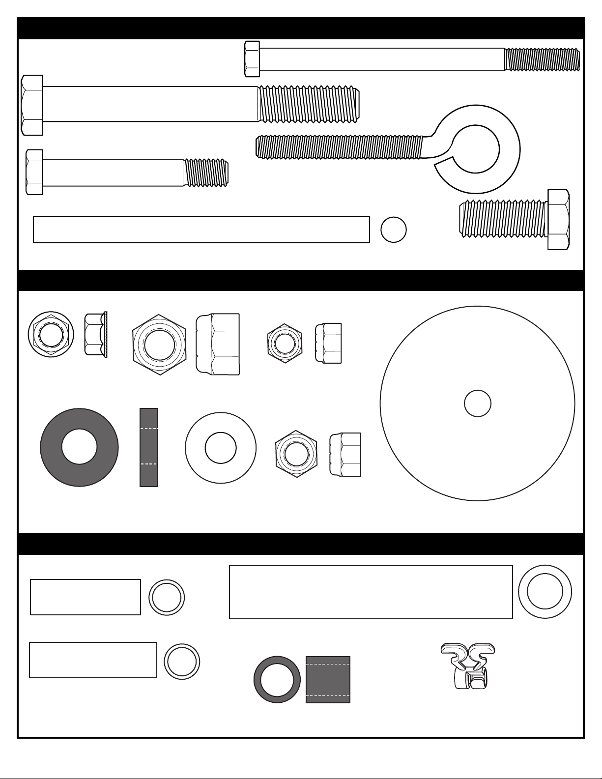
HARDWARE IDENTIFIER (BOLTS)
Item #23 (1)
Item #22 (4)
Item #11 (1)
Item #8 (1)
Item #17 (8)
Item #27 (4)
Item #7 (1)
Item #37 (4)
HARDWARE IDENTIFIER (NUTS & WASHERS)
Item #14 (1)
Item #35 (7)
Item #21 (18)
Item #10 (1)
Item #9 (5)
Item #16 (2)
Item #38 (2)
HARDWARE IDENTIFIER (OTHER)
Item #39 (2)
Item #33 (6)
7
Item #19 (12)
05/04 P/N 211472
Page 8
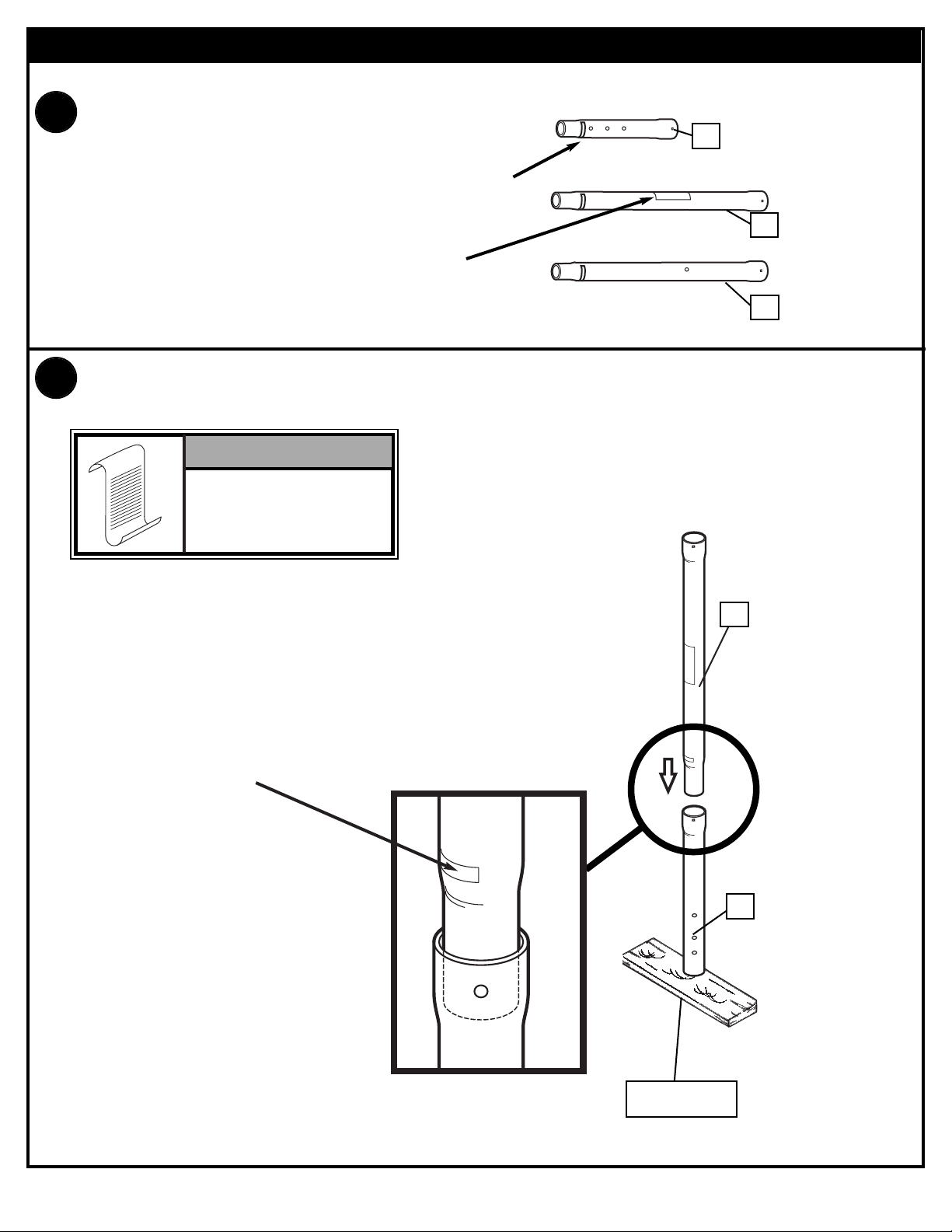
SECTION A: ASSEMBLE THE POLES
1.
2.
Correctly identify each pole section.
POLE IDENTIFICATION
TOP
4
MIDDLE
MARK
5
BOTTOM
WARNING
LABEL
Bounce pole top (4) and middle section (5) together as shown until they no longer
move toward pole identification mark. Upright assembly.
6
NOTE:
POLE SECTIONS
SHOULD HAVE A
3-1/2" (9 CM) MINIMUM
OVERLAP.
POLE
IDENTIFICATION
MARK
5
4
P/N 211472 05/04
WOOD SCRAP
8
Page 9

3.
Bounce top and middle pole assembly and bottom pole (6) together as shown
until they no longer move toward pole identification mark.
NOTE:
POLE SECTIONS
SHOULD HAVE A
3-1/2" (9 CM) MINIMUM
OVERLAP.
IMPORTANT!:
Holes in top (1) and
bottom pole (3) sections
MUST align to correctly
position elevator system
toward playing surface.
4
5
POLE
IDENTIFICATION
MARK
WOOD SCRAP
SUPPLIED)
(NOT
6
9
05/04 P/N 211472
Page 10

SECTION B: ASSEMBLE THE BASE
This is what your system will look like when
you’ve finished this section:
TOOLS REQUIRED FOR THIS SECTION
9/16” and 1/2”
OR
9/16” and 1/2”
HARDWARE USED IN THIS SECTION
(not actual size)
Item #7
Item #8
Item #11
Item #10
Item #27
Item #14
Item #17
Item #14
Item #17
Item #21
P/N 211472 05/04
Item #23
10
Page 11

1.
Install rod (7) through holes in bottom pole (6) section and eyebolt
(8).
6
7
8
2.
Install wheel axle (2) through support foot (24) and install wheels (3)
onto wheel axle (2) with spacers (27) as shown.
24
3
27
27
27
2
3
27
11
05/04 P/N 211472
Page 12

3.
Insert pole assembly into tank assembly as shown.Secure pole
assembly to tank and wheel bracket as shown. Note orientation of
support foot.
WARNING!
TWO PEOPLE REQUIRED
FOR THIS PROCEDURE.
FAILURE TO FOLLOW THIS
WARNING COULD RESULT
IN SERIOUS INJURY AND/OR
PROPERTY DAMAGE.
6
8
P/N 211472 05/04
9
10
12
Page 13

4.
Secure tank struts (12 & 13) to pole.
Nut (14) should be tightened until flush (even) with locknuts outer edge.
11
12
21
21
12
12
14
13
13
TOP VIEW
12
13
1
13
WARNING!
1) IN
TIGHTEN BOL
LOCK NUT (14) UNTIL
FLUSH (EVEN) WITH LOCK
NUT’S OUTER EDGE.
T (1
13
05/04 P/N 211472
Page 14

Rotate all non-secured ends of tank struts to mounting holes in tank as shown.
5.
Secure non-secured ends of tank struts to tank as shown.
23
21
9
17
P/N 211472 05/04
14
Page 15

SECTION C: ASSEMBLE THE BACKBOARD
This is what your system will look like when
you’ve finished this section:
TOOLS REQUIRED FOR THIS SECTION
1/2”
OR
1/2”
HARDWARE USED IN THIS SECTION
Item #35
Item #21
Item #38
Item #19
Item #10
Item #33
Item #37
15
Item #22
05/04 P/N 211472
Page 16

1.
Install screw jack support plates (29 & 30) to
pole using bolts (32) washers (31) and (35)
as shown.
30
32
1
TOP VIEW
30
29
35
32
FRONT OF SYSTEM
34
29
34
FRONT OF SYSTEM
35
P/N 211472 05/04
16
Page 17

Attach height decal (31) to
1
7
9
8
1
9
8
8'
2.4m
2.
screw jack (36). Align lower
36
edge of decal with bottom of
black indicator tube.
31
Center screw jack (35) between jack plates (29 & 30)) and secure as shown below.
3.
Do not overtighten.
FRONT VIEW
OF ASSEMBLY
34
IMPORTANT!:
DO NOT OVER
TIGHTEN
34
Place cover (40)
4.
over screw jack (36).
Install pole cap (41).
37
41
30
POLE
40
21
35
35
21
37
29
FRONT VIEW OF
ASSEMBLY
35
36
17
05/04 P/N 211472
Page 18

½
8'
2.4m
5.
Secure upper elevator tubes (33) to
pole assembly as shown.
32
33
31
31
35
33
IMPORTANT!:
DO NOT OVER
TIGHTEN
35
34
33
39
41
33
34
SCREW JACK
ASSEMBLY
32
Insert spacer (39) through top
6.
holes of height indicator cover
(41) and screw jack assembly as
shown. Align spacer (39) and
screw jack assembly between
elevator tubes (33) and secure.
IMPORTANT!
#39
WHEN SECURING SCREW JACK
ASSEMBLY TO TOP ELEVATOR
TUBES (33), USE SPACER (39)
BETWEEN ELEVATOR TUBES
AS SHOWN.
P/N 211472 05/04
18
Page 19

Assemble backboard brackets (20) using
7.
spacers (16) bolts (22) and nuts (10) as shown.
20
Add reinforcement spacers (38) to bpard
brackets (20) in locations shown.
38
38
16
10
16
10
22
22
10
8.
22
Refer To Instructions
Included With Rim
Hardware For Rim
Assembly.
19
05/04 P/N 211472
Page 20

Assemble backboard to elevator tubes (33 & 34) as shown.
½
9.
WARNING!
32
Upper Tube
STRAIGHT ON VIEW
20
33
33
33
35
Upper Tube
TWO PEOPLE REQUIRED
FOR THIS PROCEDURE.
FAILURE TO FOLLOW THIS
WARNING COULD RESULT IN
SERIOUS INJURY AND/OR
PROPERTY DAMAGE.
WARNING!
DO NOT LEAVE
ASSEMBLY UNATTENDED
WHEN EMPTY; IT MAY TIP
OVER.
Lower Tube
Lower Tube
P/N 211472 05/04
20
Page 21

10.
Install clips.
USE OF THIS PRODUCT
WITHOUT PROPER
NSTALLATION OF SMART
I
CLIPS
CLIPS®ARE NOT PRESENT
COULD RESULT IN BODILY
HARM. BE SURE TO FOLLOW
DIRECTIONS CAREFULLY.
18
WARNING!
®
, OR WHEN ALL SMART
Insert one “arm” of clip into ram as shown. Twist “body” of clip
slightly so that second “arm” slides over the top of the first
“arm” as shown.
CLIP “ARM”
CLIP “BODY”
19
Push in direction indicated by arrow.
AA
Push second “arm” back and into ram as shown.
BB
Twist “body” of clip slightly again to spread “arms” of clip.
Clip “arms” must be flat and touching edge to edge as shown,
not overlapping.
CC
21
05/04 P/N 211472
Page 22

NET INSTALLATION
10.
18
19
25
Insert net into bottom of clip as shown.
SIDE VIEW
NETCLIP
NET
P/N 211472 05/04
Twist net until it snaps into position.
Net must be centered through clip.
22
SIDE VIEW
NETCLIP
NET
Page 23

SECTION D: SECURING THE SYSTEM
Place assembled unit to desired location. Fill tank with water (28 gallons (114 liters))
1.
or sand (360 lb. (163 kg)) and snap tank cap (28) in place.
CAUTION!
ADD TWO GALLONS (7.6
LITERS) OF NON-TOXIC
ANTIFREEZE IN SUBFREEZING CLIMATES.
28
NOTE:
IF FILLING WITH SAND:
SAND
SAND
(360 lb.)
(360 lb.)
(163 kg)
(163 kg)
2 GALLONS OF ANTI-
FREEZE IS NOT
REQUIRED
Secure system rigidly to a flat,
solid (preferably concrete)
surface using lag bolts or a
similar anchoring system
through holes in support feet as
shown.
This step must be done to
conform to EN1270 standards.
WARNING!
TWO PEOPLE REQUIRED
FOR THIS PROCEDURE.
FAILURE TO FOLLOW THIS
WARNING COULD RESULT IN
SERIOUS INJURY AND/OR
PROPERTY DAMAGE.
23
05/04 P/N 211472
Page 24

Size = 4" x 5.5"
Corner Radius = 3/8"
Die Cut Label
3.25 Mil Vinyl
A
ll Temp. Permanent Adhesive
1 Mil. Polypropolyne Overlaminate
Illustrator 8.0 = EPS
B
acking + 1/16 Circumference
Rolls of 500
Crank
Height
Indicator
Hook
201254 2/99
1
2
4
3
MOVING SYSTEM
1. Adjust basketball backboard
height to lowest position.
2. Rotate basketball system
forward, while holding pole,
until wheels engage with
ground.
3.
Move basketball system to
desired location.
4. Carefully rotate basketball
system upright.
5. Reattach ground restraint and
check system for stability.
HEIGHT ADJUSTMENT
TO ADJUST BACKBOARD:
Position looped end of crank
onto hook as shown. Rotate
crank handle to raise or lower
backboard.
S
ize = 4" x 3"
C
orner Radius = 3/8"
D
ie Cut Label
3
.25 Mil Vinyl
A
ll Temp. Permanent Adhesive
1
Mil. Polypropolyne Overlaminate
I
llustrator 8.0 = EPS
B
acking + 1/16 Circumference
R
olls of 500
2
01261 3/99
1
3
2
M
OVINGSYSTEM
1
.While holding pole, rotate
b
asketball system forward
until wheels engage with
g
round.
2
.Move basketball system to
d
esired location.
3
.Carefully rotate basketball
s
ystem upright.
4
.Reattach ground restraint and
c
heck system for stability.
S
ize = 4" x 5.5"
C
orner Radius = 3/8"
D
ie Cut Label
3
.25 Mil Vinyl
A
ll Temp. Permanent Adhesive
1
Mil. Polypropolyne Overlaminate
I
llustrator 8.0 = EPS
B
acking + 1/16 Circumference
R
olls of 500
Crank
H
eight
I
ndicator
H
ook
2
01254 2/99
1
2
4
3
MOVINGSYSTEM
1
.Adjust basketball backboard
h
eight to lowest position.
2
.Rotate basketball system
f
orward, while holding pole,
u
ntil wheels engage with
g
round.
3
.
M
ove basketball system to
d
esired location.
4
.Carefully rotate basketball
s
ystem upright.
5
.Reattach ground restraint and
c
heck system for stability.
HEIGHTADJUSTMENT
T
OADJUSTBACKBOARD:
P
osition looped end of crank
o
nto hook as shown. Rotate
c
rank handle to raise or lower
b
ackboard.
SECTION E: APPLY HEIGHT AND MOVING LABEL
1.
Apply Moving Label (15) to front of pole, where it is clearly visible.
15
P/N 211472 05/04
24
Page 25

SECTION G: HEIGHT ADJUSTMENT
1.
Position looped end of height adjustment crank
(42) onto hook as shown. Rotate crank handle
to raise or lower backboard. View label (31) to
determine approximate backboard height.
NOTE: If height adjustment is difficult to
operate, you may have over tightened the
areas indicated.
Regulation Rim
Height is
10 feet (3.05 m).
WARNING!
STORE CRANK OUT OF
REACH OF CHILDREN.
DO NOT ALLOW
CHILDREN TO ADJUST
HEIGHT WITHOUT ADULT
SUPERVISION, COULD
RESULT IN SERIOUS
BODILY HARM AND/OR
PROPERTY DAMAGE.
WARNING!
DO NOT ALLOW
CHILDREN TO
ADJUST HEIGHT.
NOTE: If height adjustment is
difficult to operate, you may have
over tightened the areas
indicated. Refer to Steps 16, 18,
20, and 23.
HOOK
25
31
42
05/04 P/N 211472
 Loading...