

Reifendruck-Kontrollsystem
Tire pressure monitoring system
1 Description of the system
The tire pressure monitoring system is applied for the permanent control of the tire pressure during
driving and also during standstill periods.
An electronic system which is installed in the interior of the tire measures the tire pressure and the
temperature in regular intervals and transmits information to a central control unit by means of a high
frequency transmission line. The control unit evaluates the incoming data and transmits the information
to the driver, if required. In the case of a puncture, the driver is given a warning, and he is also informed
when the tire pressure should be corrected.
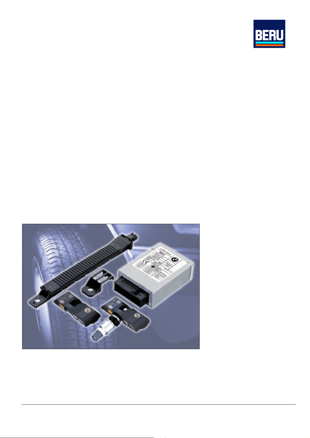
2 System components
The tire pressure control system consists of the following components:
• or 5 aluminium valves
• 4 or 5 electronic units in the wheels (sensor and high-frequency sending unit)
• 4 or 5 receiving antennas
• a special connecting cable appropriate for high-frequency transmission, between the receiving
antennas and the control unit
• a control unit (high-frequency receiver and evaluation system)
•
option: keying device for entering a default pressure
Figure 1: components of the tire pressure monitoring system
At present, an individual output unit is not available, since the output of the messages to the driver is
done via the driver information system belonging to the standard equipment.
Seite 1 von 4
Reifendruck-Kontrollsystem
Tire pressure monitoring system
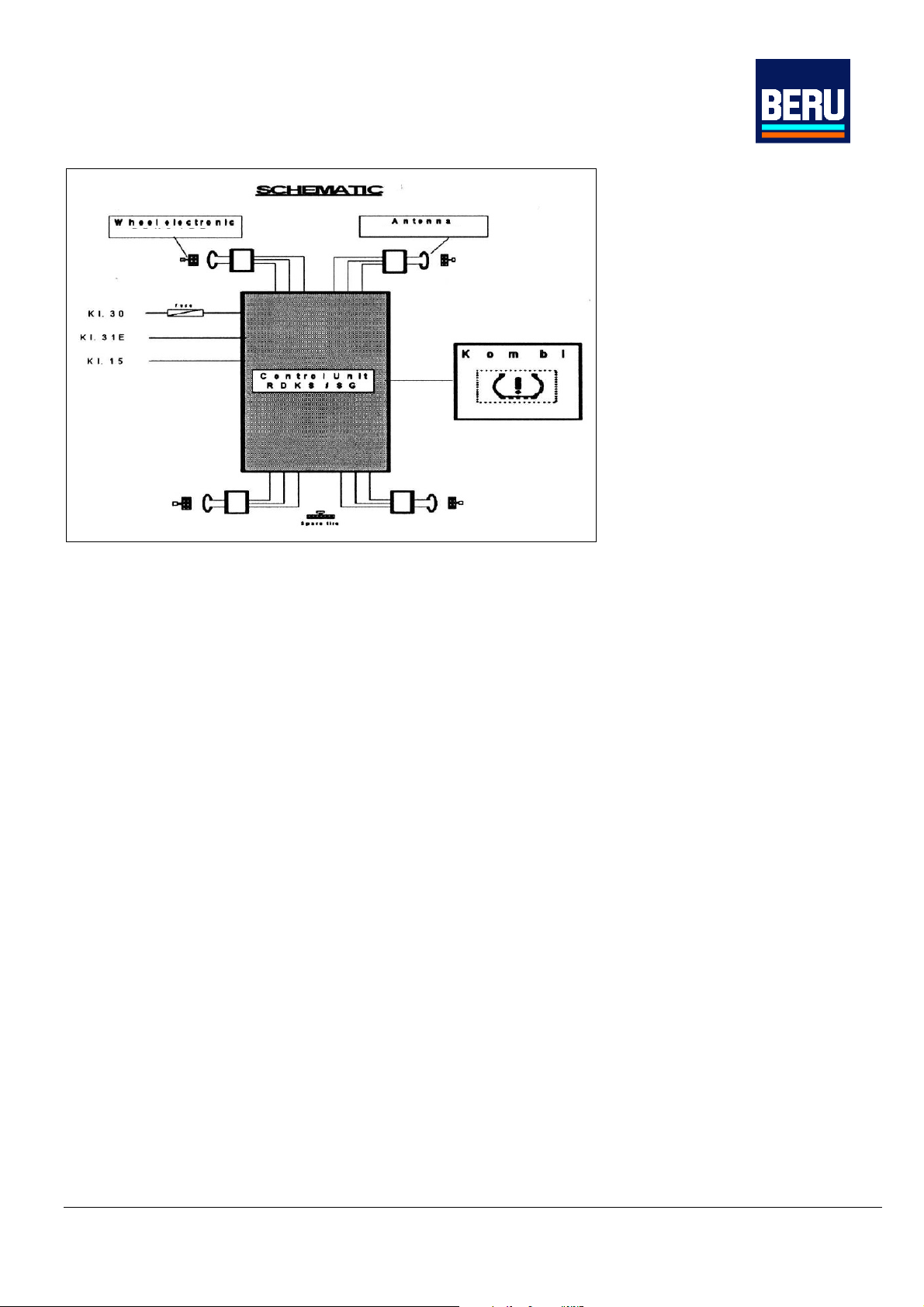
Figure 2: schematic representation of the system´s layout in a vehicle
2.1 Electronic wheel unit
The battery-based electronic wheel units are mounted inside the tires to measure the tire pressure
and the temperature of the electronic wheel systems. Every electronic wheel unit
has an individual code (ID), which is transmitted with every message. Furthermore, the data telegram
includes information about the remaining service life of the battery.
The measured data are transmitted from the wheel through a transmission point.
A tire pressure monitoring system has to carry out two main functions: The recognition of a pressure
loss and the measurement of the absolute pressure.
For the measurement of the absolute pressure, a relatively low frequency of measurement data
transmissions is sufficient, a pressure loss must be transmitted immediately. The electronic wheel
system shifts automatically to the various operating modi in order to carry out these functions at a
minimum power consumption.
Transmitting intervals
• Normally, every electronic wheel unit measures the tire pressure and the approximate
temperature of the air in the tire every three seconds but if the measured values are stable, sending
processes are carried out only every 54 seconds.
• At a pressure loss of more than 0.2 bar per minute, the electronic wheel unit shifts temporarily to
a high transmission frequency. It will then carry out measurements and sending processes every
0.8 seconds. This energy management allows battery-based operation with a sufficient service life.
Seite 2 von 4

Reifendruck-Kontrollsystem
Tire pressure monitoring system
Abbildung 3: components of the tire pressure monitoring system
The electronic wheel unit is combined with the aluminium valve to form a compact unit which is
bolted to the standardized valve bore of the rim.
Its design allows mounting in almost every known rim type. The electronic wheel unit includes an
intelligent integrated sensor which is mounted on a circuit carrier and has been developed especially
for this application. In its SMD housing, the two-chip integrated sensor contains a pressure sensor
element and an ASIC (Application Specific Integrated Circuit) with temperature sensor, measurement
acquisition unit and a signal conditioning unit. This sensor directly controls a high-frequency sending
unit. The power supply to the sensor and the sending unit is done by an environmental friendly lithium
battery which has been developed especially for the high demands on temperature resistance,
acceleration resistance and service life. In combination with the tire monitoring control unit, the typical
service life is 7 years.
2.2 Control Device
The control device consists of a high-frequency receiving module, a control device plate with
microprocessor control and the bus and diagnosis interfaces. It evaluates the received data and transmits
the information to the driver information system. It is installed in a standard series housing.
3 High Frequency transmission
The applied technique is a unidirectional high-frequency transmission of the measuring data from the
wheel to the vehicle. The high-frequency transmission is carried out in the 433-MHz- range, the socalled
ISM band or, in several countries, in the 315 MHz range. The system has been given approval
by the telecommunication authorities of the relevant countries. The data sent by the electronic wheel
system are received by the antennas mounted in the wheels and are transmitted to the control unit by
screened twisted pair cables.
Seite 3 von 4

Reifendruck-Kontrollsystem
Tire pressure monitoring system
4 FCC Requirements
Section 15.19: Labeling requirements
This device complies with Part15 of the FCC Rules.
Operation is subject to the following two conditions:
(1) this device may not cause harmful interference, and
(2) this device must accept any interference received, including interference that may cause undesired
operation.
Section 15.21: Information to the user
The user manual or instruction manual for an intentional or unintentional radiator shall caution the user that
changes or modifications not expressly approved by the party responsible for compliance could void the
user’s authority to operate the equipment.
5 IC statement according to RSS210
5.11 User Manual
Operation is subject to the following two conditions:
(1) this device may not cause interference, and
(2) this device must accept any interference, including interference that may cause undesired operation of the
device
6 Safety Instructions
Safety instructions for battery:
Dispose of used batteries in accordance with local legislation.
Safety instructions for antenna:
The antenna in the wheel housing and the plug connector is protected against splash-water.
The inlets has to be protected from the automobile manufacturer against squeezing .
For further details refer the specification 3539 20 000 001 00.
Safety instructions for wheel electronic:
The wheel electronics are mounted with a valve on the rim and sit in the drop center of the rim.
The BERU assembly guidelines must be followed during assembly.
Torque for attachment: 3.5 .. 4Nm
Max. operating temperature: -40°C … 120°C
Max. air pressure: 1400kPa
Measuring range: 50kPa … 637,5kPa
Seite 4 von 4
 Loading...