

Huebsch ZA3820*A Top-Load Parts Diagram
W138P
Automatic
Washers
Refer to Page 6 for Model Numbers
Service
www.alliancelaundry.com
Part No. 37593R2
November 2016


Table of Contents
Section 1 – Safety Information
Locating an Authorized Servicer ............................4
Section 2 – Introduction
Customer Service ....................................................5
Nameplate Location ................................................5
Model Identification ................................................6
Section 3 – Troubleshooting
1. No Hot Water ...................................................7
2. No Cold Water .................................................7
3. No Warm Water ...............................................8
4. Water Fill Does Not Stop At Proper Level ......8
5. Timer Does Not Advance (Mechanical Tim er
Models Only) ...................................................9
6. Motor Does Not Run ......................................10
7. No Agitation ...................................................10
8. Constant Agitation .........................................11
9. Washer Smokes, Overheats, Cycles On Motor
Thermal Overload Protector, Switch Actuator
Kicks In And Out ...........................................11
10. Slow Spin Or No Spin ....................................12
11. Constant Spin .................................................12
12. Washer Stops In Cycle; Quits After A Couple
Loads; Is Intermittent .....................................13
13. Washer Is Locked Up Or Binding ..................13
14. Outer Tub Does Not Empty ...........................13
15. Excessive Vibration .......................................14
16. Water Leaking From Outer Tub .....................14
17. Troubleshooting Coin Drop ...........................15
Electronic Control Models
18. Error Code Listing .........................................17
19. Cannot Perform Infrared Communication .....19
20. Coins Ignored When Entered .........................20
21. Electronic Control Has No Visible Display ...21
22. No Fill Analysis .............................................22
23. No Motor Run — Agitate Analysis ...............24
24. No Motor Run — Spin Analysis ....................26
25. Overflow Analysis .........................................28
26. Audit Switch Function Analysis ....................30
Section 4 – Grounding
27. Wall Receptacle Polarity Check ....................31
28. Power Cord To Control Hood, Control Hood
To The Control Panel Frame ..........................31
29. Control Hood Wire Harness To Top Left
Rear Corner Gusset Of Cabinet .....................32
30. Wire Harness To Motor .................................32
Section 5 – Service Procedures
31. Control Panel Assembly ................................33
32. Timer Assembly .............................................37
33. Meter Or Timer Case Assembly ....................39
34. Coin Drop .......................................................40
35. Drain Hose Elbow ..........................................45
36. Loading Door .................................................45
37. Front Panel .....................................................47
38. Motor And Mounting Bracket .......................47
39. Idler Lever And Pulley ...................................49
40. Motor Drive Pulley ........................................50
41. Motor Switch .................................................53
42. Agitator ..........................................................54
43. Cabinet Top Assembly ...................................54
44. Cabinet Top Assembly Removal ...................55
45. Agitato r Drive Bell and Seal Kit,
No. 39508P ....................................................56
46. Out-of-Balance Switch Assembly ..................59
47. Mixing Valve Assembly ................................60
48. Outer Tub Cover And Clothes Guard ............61
49. Hub and Seal Kit, No. 495P3 .........................65
50. Outer Tub Assembly ......................................67
51. Drive Pulley and Helix ...................................70
52. Brake Assembly ........... ......... ......... ................72
53. Lower Bearing Housing .................................73
54. Transmission Assembly .................................73
55. Balance Ring ..................................................78
56. Upper Bearing Assembly ...............................78
57. Snubber Pad and Isolator Assembly ..............79
Section 6 – Adjustments
58. Leveling Legs .................................................81
59. Pressure Switch ..............................................82
60. Out-of-Balance Switch ...................................82
61. Belt (Agitate and Spin) ..................................82
62. Idler Spring Tension ......................................83
63. Cleaning Coin Drop .......................................84
Section 7 – Test Procedures
© Copyright 2016, Alliance Laundry Systems LLC
All rights reserved. No part of the contents of this book may be reproduced or tran smitted in any form or by any means withou t
the expressed written consent of the publisher.
37593
© Copyright, Alliance Laundry Systems LLC – DO NOT COPY or TRANSMIT
(continued)
1

64. Emerson Motor Switch ..................................87
65. Emerson Motor Windings ..............................88
Section 8 – Cycle Sequence Charts
Timer No. 28716 Cycle Sequence (Long Cycle –
Kingston)................................................................89
Timer No. 31111P Cycle Sequence
(Short Cycle)..........................................................90
Timer No. 34601P Cycle Sequence
(Long Cycle)... .......................................................91
Timer No. 34602 Cycle Sequence
(Long Cycle)... .......................................................92
Section 9 – Internal Wiring of Washer Motor
Switch
.....................................................................93
2
© Copyright, Alliance Laundry Systems LLC – DO NOT COPY or TRANSMIT
37593
Section 1
• Failur e to install, maintain and/or oper a te this product according to the manufacturer’s
instructions may result in conditions which can produce serious injury, death and/or
property damage.
• Do not repair or replace any part of the product or attempt any servicing unless specifically
recommended or published in this Service Manual and unless you understand and have the
skills to carry out the servicing.
• Whenever ground wires are removed during servicing, these ground wires must be
reconnected to ensure that the product is properly grounded and to reduce the risk of fire,
electric shock, serious injury or death.
W006R2
WARNING
Safety Information
Throughout this manual and on machine decals, you will find precautionary statements (“CAUTION,”
“WARNING” and “DANGER”) followed by spe cifi c ins truct io ns. The se pr eca ut ion s are int end ed fo r the per sona l
safety of the operator, user, servicer and those maintaining the machine.
DANGER
Danger indicates an imminent ly ha zar dous situation that, if not avoided, will caus e se ver e per sona l i njury or death.
WARNING
Warning indicates a hazardous situation that, if not avoided, could cause severe personal injury or death.
CAUTION
Caution indicates a hazardous situat ion that, if not a voided, may cause minor or moderate person al injury or proper ty
damage.
Additional precautionary statements (“IMPO RTANT” a nd “NOTE”) are followed by specific instructions.
IMPORTANT
The word “IMPORTANT” is used to inform the reader of specific procedures where minor machine damage will
occur if the procedure is not followed.
NOTE
The word “NOTE” is used to communicate installation, operation, maintenance or servicing information that is
important but not hazard related.
In the interest of safety, some general precautions relating to the operation of this machine follow.
37593
© Copyright, Alliance Laundry Systems LLC – DO NOT COPY or TRANSMIT
3
Section 1 Safety Information
To reduce the risk of electric shock, fire, explosion, serious injury or death:
• Disconnect electric power to the washer before servicing.
• Never start the washer with any guards/panels removed.
• Whenever ground wires are removed during servicing, these ground wires must be
reconnected to ensure that the washer is properly grounded.
W003
WARNING
Repairs that are made to your products by unqualified persons can result in hazards due to
improper assembly or adjustments subjecting you or the inexperienced person making such
repairs to the risk of serious injury, electrical shock or death.
W007
WARNING
If you or an unqualified person perform service on your product, you must assume the
responsibility for any personal injury or property damage which may result. The manufacturer
will not be responsible for any injury or property damage arising from improper service and/or
service procedures.
W008
WARNING
NOTE: The WARNINGS and IMPORTANT INSTRUCTIONS appearing in this manual are not meant to
cover all possible conditions and situations that may occur. Common sense, caution and care must be
exercised when installing, maintaining or operating the washer.
Always contact your dealer, distributor, service agent or the manufac turer about any problems or con ditions you do
not understand.
Locating an Authorized Servicer
Alliance Laundry Systems is not responsible for personal injury or property damage resulting from improper
service. Review all service information before beginning repairs.
Warranty service must be performed by an authorized technician, using authorized factory parts. If service is
required after the warranty expires, Alliance Laundry Systems also recommends contacting an authorized
technician and using authorized factory parts.
4
© Copyright, Alliance Laundry Systems LLC – DO NOT COPY or TRANSMIT
37593
Section 2
Nameplate
Introduction
Customer Service
If literature or replacement parts are required, contact
the source from whom the machine was purchased or
contact Alliance Laundry Systems at (920) 748-3950
for the name and address of the nearest authorized
parts distributor.
For technical assistance, call (920) 748-3121.
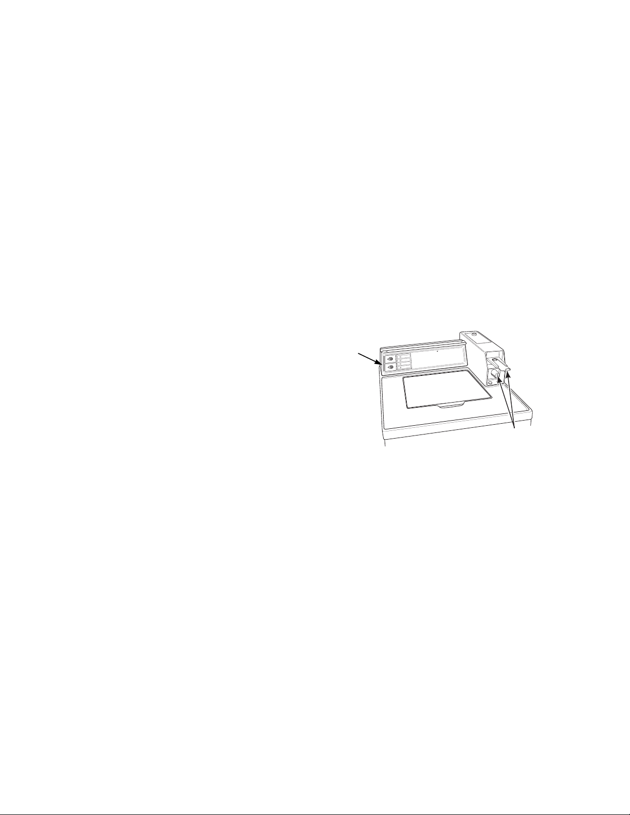
Nameplate Location
When calling or wri ting about your p rodu ct, be sure to
mention model and serial numbers. Model and serial
numbers are located on nameplate(s) as shown.
IC
R
B
A
F
L
L
A
S
S
E
R
P
T
N
E
N
A
M
R
E
P
D
E
C
N
A
L
A
B
N
U
M
R
A
W
D
A
O
L
D
L
O
C
T
O
H
E
S
U
N
I
E
R
U
T
A
R
E
M
E
T
H
S
A
W
E
S
N
I
R
S
S
E
R
P
.
M
R
E
P
E
T
A
IC
L
E
D
N
I
P
S
L
A
M
R
O
N
R
O
T
C
E
L
E
S
IC
R
B
A
F
NOTE: Coin slide and
coin drawer shown for
illustration purposes
only.
W233SE3A
37593
© Copyright, Alliance Laundry Systems LLC – DO NOT COPY or TRANSMIT
5

Section 2 Introduction
Model Identification
Information in this manual is applicable to these washe r models.
Washer
Model
DWA021*A X XX
EAJ920*A X X X X
EAJ921*A X X X X
EA2011*A X X X
EA2020*A X XX
EA2021*A X XX
EA2110*A X X X
EA2111*A X X X
EA2120*A X X X
EA2121*A X X X
EA2210*A X X X
EA2220*A X X X
EA2221*A X X X
EA2520*A X X X
EA2521*A X X X
EA2610*A X X X X
EA2620*A X X X X
EA2621*A X X X X
EA2710*A X X X X
EA2721*A X X X X
EA2820*A X X X X
EA2821*A X X X X
EA2920*A X X X X
EA2921*A X X X X
EA3820*A X X X X X
EA3821*A X X X X X
EA3920*A X X X X X
EA3921*A X X X X X
JA0110* X X X
ZA2020*A X XX
ZA2110*A X X X
ZA2120*A X X X
ZA3820*A X X X X X
ZA3821*A X X X X X
* Add suffix letter to model number to designate color . L – Almond W – White
Nonmetered
Models
Metered
Models
Computerized
Audit Control
Electronic
Display
Control
Card
Reader
One
Speed
Motor
Two
Speed
Motor
Porcelain
Washtub
Stainless
Steel
Washtub
6
© Copyright, Alliance Laundry Systems LLC – DO NOT COPY or TRANSMIT
37593
To reduce the risk of electric shock, fire, explosion, serious injury or death:
• Disconnect electric power to the washer before servicing.
• Never start the washer with any guards/panels removed.
• Whenever ground wires are removed during servicing, these ground wires must be
reconnected to ensure that the washer is properly grounded.
W003
WARNING
Section 3
Troubleshooting
IMPORTANT: Refer to appropriate model wiring diagram for aid in testing washer components.
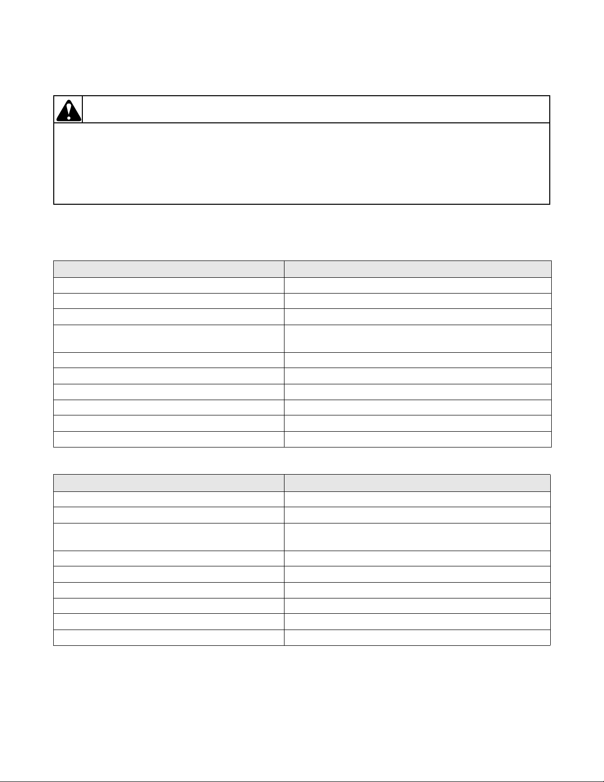
1. NO HOT WATER
POSSIBLE CAUSE TO CORRECT
Hot water su pply faucet is closed. • Open faucet.
Water supply is cold. • Check water heater.
Kinked hot water inlet hose. • Straighten or replace hose.
Clogged mixing valve screen, or clogged screen in
outer end of inlet hose nearest water supply faucet.
Inoperative hot water mixing valve solenoid. • Test solenoid and replace if inoperative.
Inoperative timer. • Test timer and replace if inoperative.
Inoperative temperature switch. • Test switch and replace if inoperative.
Inoperative pressure switch. • Test switch and replace if inoperative.
Clogged pressure hose. • Remove and clean or replace hose.
Broken, loose or incorrect wiring. • Refer to appropriate wiring diagram.
• Disconnect hot water inlet hose, and clean or replace
screen.
2. NO COLD WATER
POSSIBLE CAUSE TO CORRECT
Cold water supply faucet is closed. • Open faucet.
Kinked cold water inlet hose. • Straighten or replace hose.
Clogged mixing valve screen, or clogged screen in
outer end of inlet hose nearest water supply faucet.
Inoperative cold water mixing valve solenoid. • Test solenoid and replace if inoperative.
Inoperative timer. • Test timer and replace if inoperative.
Inoperative temperature switch. • Test switch and replace if inoperative.
Inoperative pressure switch. • Test switch and replace if inoperative.
Clogged pressure hose. • Remove and clean or replace hose.
Broken, loose or incorrect wiring. • Refer to appropriate wiring diagram.
• Disconnect cold water inlet hose, and clean or replace
screen.
37593
© Copyright, Alliance Laundry Systems LLC – DO NOT COPY or TRANSMIT
7
Section 3 Troubleshooting
To reduce the risk of electric shock, fire, explosion, serious injury or death:
• Disconnect electric power to the washer before servicing.
• Never start the washer with any guards/panels removed.
• Whenever ground wires are removed during servicing, these ground wires must be
reconnected to ensure that the washer is properly grounded.
W003
WARNING
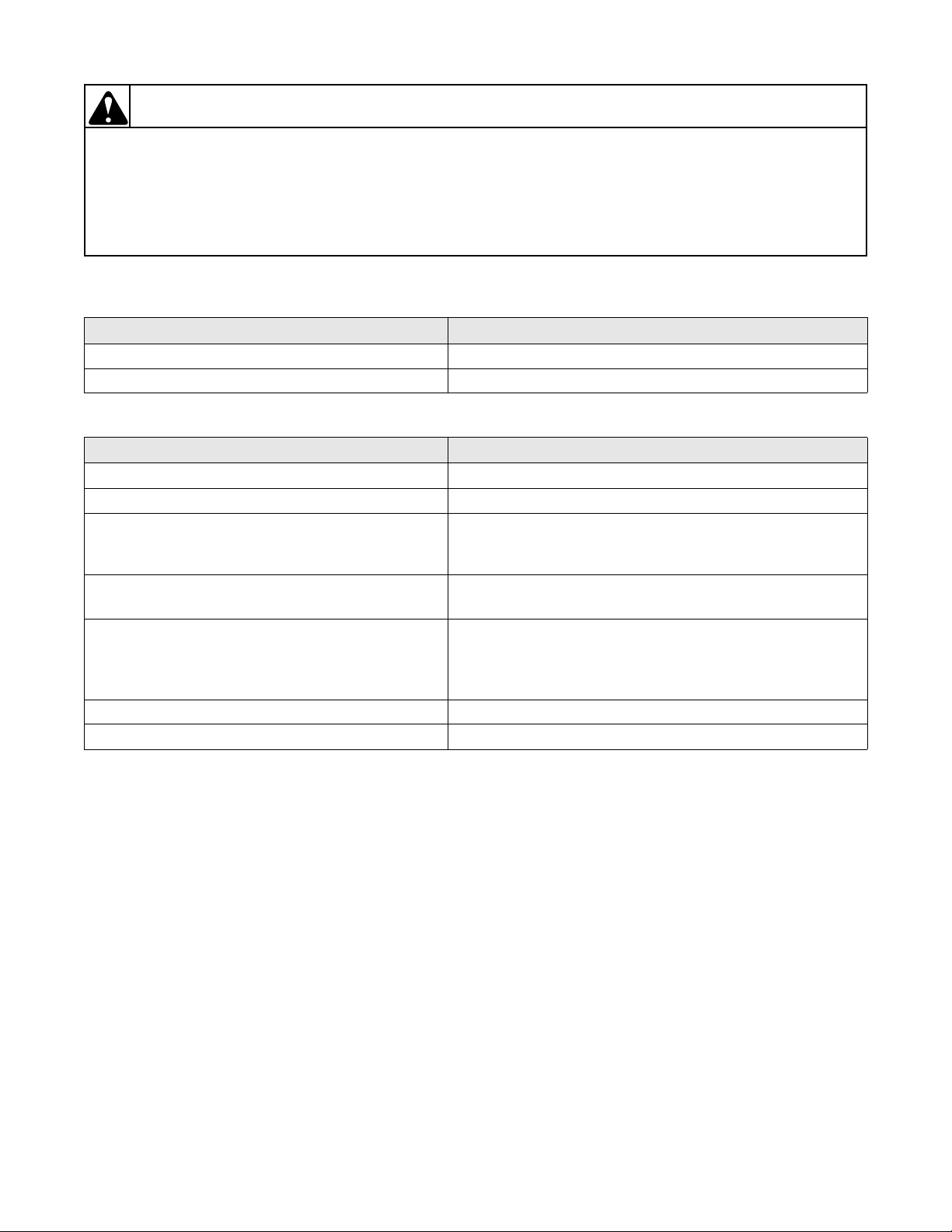
3. NO WARM WATER
POSSIBLE CAUSE TO CORRECT
No hot water. • Refer to Paragraph 1.
No cold water. • Refer to Paragraph 2.
4. WATER FILL DOES NOT STOP AT PROPER LEVEL
POSSIBLE CAUSE TO CORRECT
Inoperative pressure switch. • Test switch and replace if inoperative.
Air leak in pressure hose. • Replace hose.
Sediment on or under mixing valve diaphragm,
defective diaphragm, or armature binding in
• Disassemble and clean mixing valve. Replace if
deteriorated or not easily cleaned.
armature guide.
Broken, weak or missing mixing valve armature
• Disassemble valve and replace spring.
spring.
A siphoning action started in washer will cause
water to be siphoned from washer during cycle due
• Install No. 562P3 Siphon Break Kit. Provide an air gap
around drain hose and drain receptacle.
to end of drain hose being lower th an cabine t top of
washer. Drain hose fits tight in standpipe or drain.
Water in pressure hose. • Blow air through hose to remove water.
Broken, loose, shorte d or incorre ct wiring. • Refer to appropriate wiring diagram.
8
© Copyright, Alliance Laundry Systems LLC – DO NOT COPY or TRANSMIT
37593
Section 3 Troubleshooting
To reduce the risk of electric shock, fire, explosion, serious injury or death:
• Disconnect electric power to the washer before servicing.
• Never start the washer with any guards/panels removed.
• Whenever ground wires are removed during servicing, these ground wires must be
reconnected to ensure that the washer is properly grounded.
W003
WARNING
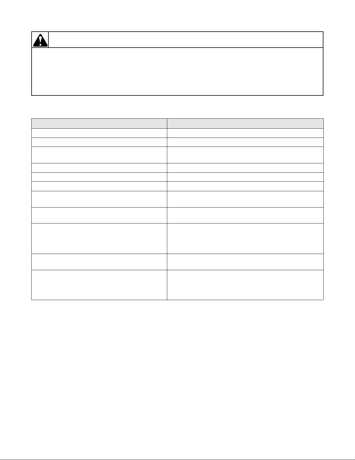
5. TIMER DOES NOT ADVANCE (Mechanical Timer Models Only)
POSSIBLE CAUSE TO CORRECT
Timer is designed to pause during fill periods. • Allow completion of fill period.
Inoperative timer. • Test timer, and replace if inoperative.
Loading door is open. • Close loading door. Loading door MUST be closed any
time the washer is set to fill, agitate or spin.
Washer will not fill. • Timer pauses until pressure switch is satisfied.
Timer motor lead wire off timer terminal. • Refer to appropriate wiring diagram and reattach wire.
Broken, loose or incorrect wiring. • Refer to appropriate wiring diagram.
Timer is design ed to pause when go ing from agi tate
to spin.
Timer is designed to stop if an out-of-balance load
has been encountered while washing clothes load.
Timer is design ed to st op if washe r dri ve motor has
been over loaded and motor thermal overload has
tripped.
• Allow time for timer to go through that step. Refer to
diagram for information on t ime required.
• Open lid and automatically reset out-of-balance switch
when lid is closed.
• Motor thermal protector reset time may vary depending
upon the reason for the washer overload, however, it
should reset within 15 minutes. Check to ensure that
washer was not overloaded with clothes.
Circuit breaker to washer may have tripped,
• Reset circuit breaker.
disconnecting power to washer.
Washer will not fill. • Timer is designed to pause when going from spin into
rinse to allow the washt ub t o st op s pin nin g bef o r e fill i ng.
Make sure that t imer has advanced i nto fill portion of rinse
cycle.
37593
© Copyright, Alliance Laundry Systems LLC – DO NOT COPY or TRANSMIT
9
Section 3 Troubleshooting
To reduce the risk of electric shock, fire, explosion, serious injury or death:
• Disconnect electric power to the washer before servicing.
• Never start the washer with any guards/panels removed.
• Whenever ground wires are removed during servicing, these ground wires must be
reconnected to ensure that the washer is properly grounded.
W003
WARNING
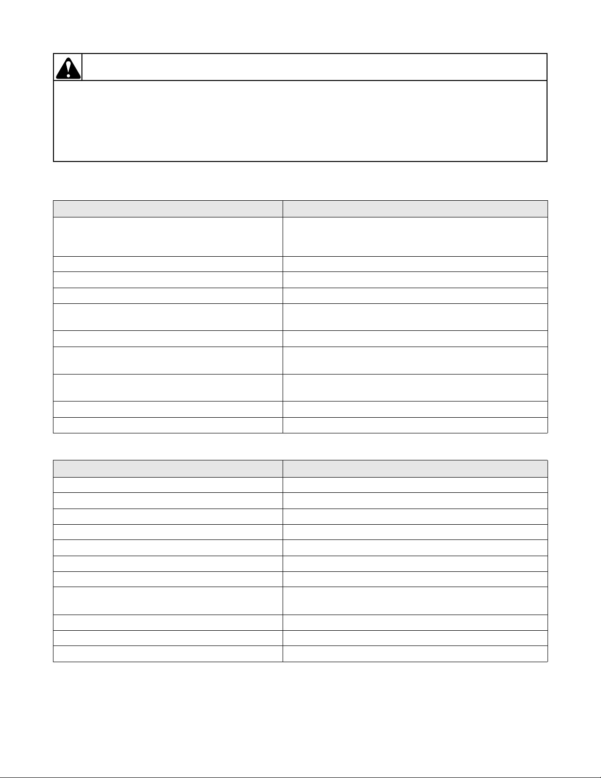
6. MOTOR DOES NOT RUN
POSSIBLE CAUSE TO CORRECT
Electrical power off, fuse blown or power cord not
plugged in.
• Check laundry room for blown or loose fuse(s) or open
circuit breakers. ( Washer itsel f does not have an electrical
fuse).
Loading door not closed or inoperative switch. • Close door or test switch and replace if inoperative.
Timer improperly set. • Reset timer, or try another cycle.
Inoperative timer. • Test timer and replace if inoperative.
Motor starting functions inoperative. No start; or
• Refer to Section 7 to check start switch and start windings.
motor hums only.
Motor is dead, won’t run. • Refer to Section 7 to check switch and windings.
Motor overload protector has cycle d. • Wait two or three min utes for overload protector t o reset.
If protector cycles repeatedly, refer to Paragraph 9.
Bind in upper or lower motor bearing. • Remove belt and determine if motor shaft will spin.
Replace moto r if shaft is locked up.
Broken, loose or incorrect wiring. • Refer to appropriate wiring diagram.
Power cord is miswired. • Refer to appr opriate wiri ng diagram for correct wiring.
7. NO AGITATION
POSSIBLE CAUSE TO CORRECT
Inoperative timer. • Test timer and replace if inoperative.
Inoperative action switch. • Test switch and replace if inoperative.
Motor will not run. • Refer to Section 7 to check switch and windings.
Inoperative pressure switch. • Test switch and replace if inoperative.
Broken, loose or incorrect wiring. • Refer to appropriate wiring diagram.
Broken drive belt. • Replace belt.
Inoperative transmission assembly. • Replace transmission assembly.
Sheared motor pulley roll pin. • Remove drive motor and replace roll pin and any other
damaged parts.
Drive motor overload protector has cycled. • Refer to Paragraph 9.
Bind in pump. • Replace pump.
Loading door is open or door switch is inoperative. • Close door or test switch and replace if inoperative.
10
© Copyright, Alliance Laundry Systems LLC – DO NOT COPY or TRANSMIT
37593

Section 3 Troubleshooting
To reduce the risk of electric shock, fire, explosion, serious injury or death:
• Disconnect electric power to the washer before servicing.
• Never start the washer with any guards/panels removed.
• Whenever ground wires are removed during servicing, these ground wires must be
reconnected to ensure that the washer is properly grounded.
W003
WARNING
8. CONSTANT AGITATION
POSSIBLE CAUSE TO CORRECT
Inoperative timer. Test timer and replace if inoperative.
Shorted or incorrect wiring. Refer to appropriate wiring diagram.
Inoperative transmission assembly. Repair or replace transmission assembly.
9. WASHER SMOKES, OVERHEATS, CYCLES ON MOTOR THERMAL OVERLOAD PROTECTOR, SWITCH ACTUATOR KICKS IN AND OUT
POSSIBLE CAUSE TO CORRECT
Belt is tacky and does not allow proper slip. Check belt and replace if defective.
Belt tension is too great and does not allow proper
Make sure idler spring is properly connected.
slip.
Inoperative timer. Test timer and replace if inoperative.
Motor switch functions inoperative. Refer to Section 7 to check switch functions.
Bind in water pump. Replace pump.
Brake pads or brake assembly binding. Free binding pads, or replace pads and brake assembly.
Bearings, transmission or motor has locked up and
will not turn.
Check that all these components are able to move freely.
Correct binding component.
Incorrect voltage. Contact local util ity company, or ha ve a qualified ele ctrician
check power supply.
37593
© Copyright, Alliance Laundry Systems LLC – DO NOT COPY or TRANSMIT
11
Section 3 Troubleshooting
To reduce the risk of electric shock, fire, explosion, serious injury or death:
• Disconnect electric power to the washer before servicing.
• Never start the washer with any guards/panels removed.
• Whenever ground wires are removed during servicing, these ground wires must be
reconnected to ensure that the washer is properly grounded.
W003
WARNING
10. SLOW SPIN OR NO SPIN
POSSIBLE CAUSE TO CORRECT
Inoperative timer. • Test timer and replace if inoperative.
Loading door is open or door safety switch is
inoperative.
• Close loading door, or test switch and replace if
inoperative.
Bind in water pump. • Replace pump.
Broken or worn drive belt. • Replace belt.
Motor will not run. • Refer to “Motor Test” Section 7 to check switch and
windings.
Sheared motor pulley roll pin. • Remove drive motor and appropriately replace roll pin
and any other damaged parts.
Motor overload protector has cycle d. • Wait two or three min utes for overload protector t o reset.
If protector cycles repeatedly, refer to Paragraph 9.
No clearance between brake pads and discs. • Replace pads and brake assembly.
Broken, loose or incorrect wiring. • Refer to appropriate wiring diagram.
Inoperative transmission assembly. • Repair or replace the transmission assembly.
Lack of idler spring tension. • Adjust motor bracket. Refer to Paragraph 62.
11. CONSTANT SPIN
POSSIBLE CAUSE TO CORRECT
Inoperative timer. Test timer and replace if inoperative.
Washtub does not stop spinning within seven
Replace brake pads and brake assembly.
seconds after loading door is opened.
Excessive wear on brake pads, or missing brake
Replace brake pads and brake assembly.
pads.
Shorted or incorrect wiring. Refer to appropriate wiring diagram.
12
© Copyright, Alliance Laundry Systems LLC – DO NOT COPY or TRANSMIT
37593
Section 3 Troubleshooting
To reduce the risk of electric shock, fire, explosion, serious injury or death:
• Disconnect electric power to the washer before servicing.
• Never start the washer with any guards/panels removed.
• Whenever ground wires are removed during servicing, these ground wires must be
reconnected to ensure that the washer is properly grounded.
W003
WARNING
12. WASHER STOPS IN CYCLE; QUITS AFTER A COUPLE LOADS; IS INTERMITTENT
POSSIBLE CAUSE TO CORRECT
Belt is tacky and does not allow proper slip. • Check belt and replace if defective.
Belt tension is too great and does not allow proper
• Make sure idler spring is properly c onnected.
slip.
Inoperative timer. • Test timer and replace if inoperative.
Broken, loose or incorrect wiring. • Refer to appropriate wiring diagram.
Motor overload protector has cycle d. • Wait two or three min utes for overload protector t o reset.
If protector cycles repeatedly, refer to Paragraph 9.
Motor switch functions inoperative. • Refer to Section 7 to check switch functions.
Brake, transmissi on or motor ha s locked up a nd will
• Check that all these components are able to move freely.
not turn.
13. WASHER IS LOCKED UP OR BINDING
POSSIBLE CAUSE TO CORRECT
Excessive belt tension. • Adjust belts.
Bind in upper or lower bearing. • Replace bearing.
Bind in water pump. • Replace pump.
Bind in transmission. • Repair or replace transmission.
Brake pads binding. • Free binding pads, or replace pads.
Incorrect voltage. • Contact local utility company, or have a qualified
electrician check power supply.
14. OUTER TUB DOES NOT EMPTY
POSSIBLE CAUSE TO CORRECT
Kinked drain hose. • Straighten hose.
Drain hose out of clamp in back of cabinet. • Remove washer front panel and install drain hose into
clamp.
Inoperative water pump. • Replace pump.
Obstruction in outer tub outlet hose. • Remove obstruction.
37593
© Copyright, Alliance Laundry Systems LLC – DO NOT COPY or TRANSMIT
13
Section 3 Troubleshooting
To reduce the risk of electric shock, fire, explosion, serious injury or death:
• Disconnect electric power to the washer before servicing.
• Never start the washer with any guards/panels removed.
• Whenever ground wires are removed during servicing, these ground wires must be
reconnected to ensure that the washer is properly grounded.
W003
WARNING
15. EXCESSIVE VIBRATION
POSSIBLE CAUSE TO CORRECT
Unbalanced load in tub. • Stop washer, redistribute load, then restart washer.
Broken, or disconnected centering spring(s). • Connect or replace centering spring(s).
Washer is not properly leveled. • Adjust leveling legs.
Washer is installed on weak, “spongy”, carpeted or
built-up floor.
• Relocate washer, or support floor to eliminate weak or
“spongy” condition.
Incorrect or loose cabinet screws. • Replace with correct screws or tighten.
Base damaged (washer was dropped). • Replace base assembly.
Balance ring not positioned properly on
• Refer to Paragraph 55.
transmission assembly.
16. WATER LEAKING FROM OUTER TUB
POSSIBLE CAUSE TO CORRECT
Leaking water seal in outer tub. • Replace hub and seal kit assembly. Refer to Paragraph
49.
Hole in outer tub. • Replace outer tub.
Pressure hose or pressure bulb leaking. • Replace pressure hose and/or pressure bulb.
Outer tub cover gasket leaking. • Replace gasket.
Obstruction in drain causi ng water to come over top
• Remove obstruction.
of outer drain tub cover.
Tub-to-pump hose leaking at clamp. • Tighten clamp.
14
© Copyright, Alliance Laundry Systems LLC – DO NOT COPY or TRANSMIT
37593

Section 3 Troubleshooting
To reduce the risk of electric shock, fire, explosion, serious injury or death:
• Disconnect electric power to the washer before servicing.
• Never start the washer with any guards/panels removed.
• Whenever ground wires are removed during servicing, these ground wires must be
reconnected to ensure that the washer is properly grounded.
W003
WARNING
DRY2B
Additional coins following
path to sensor
Coin Drop
Sensor
Coin in
Coin Slot
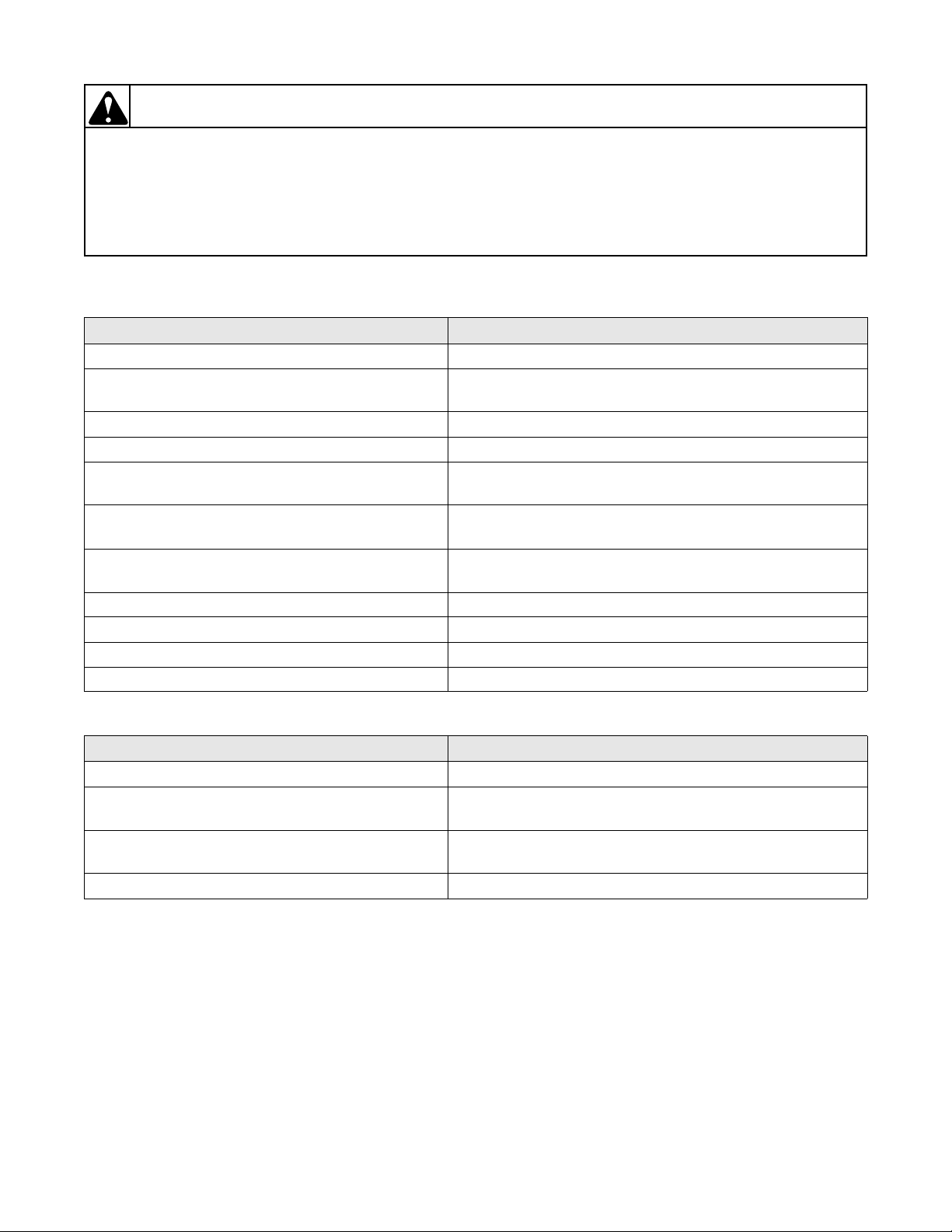
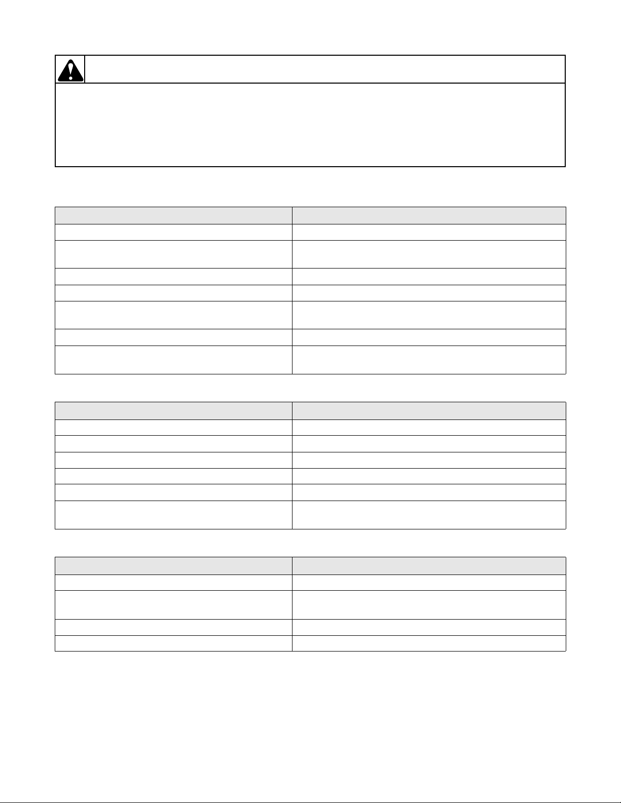
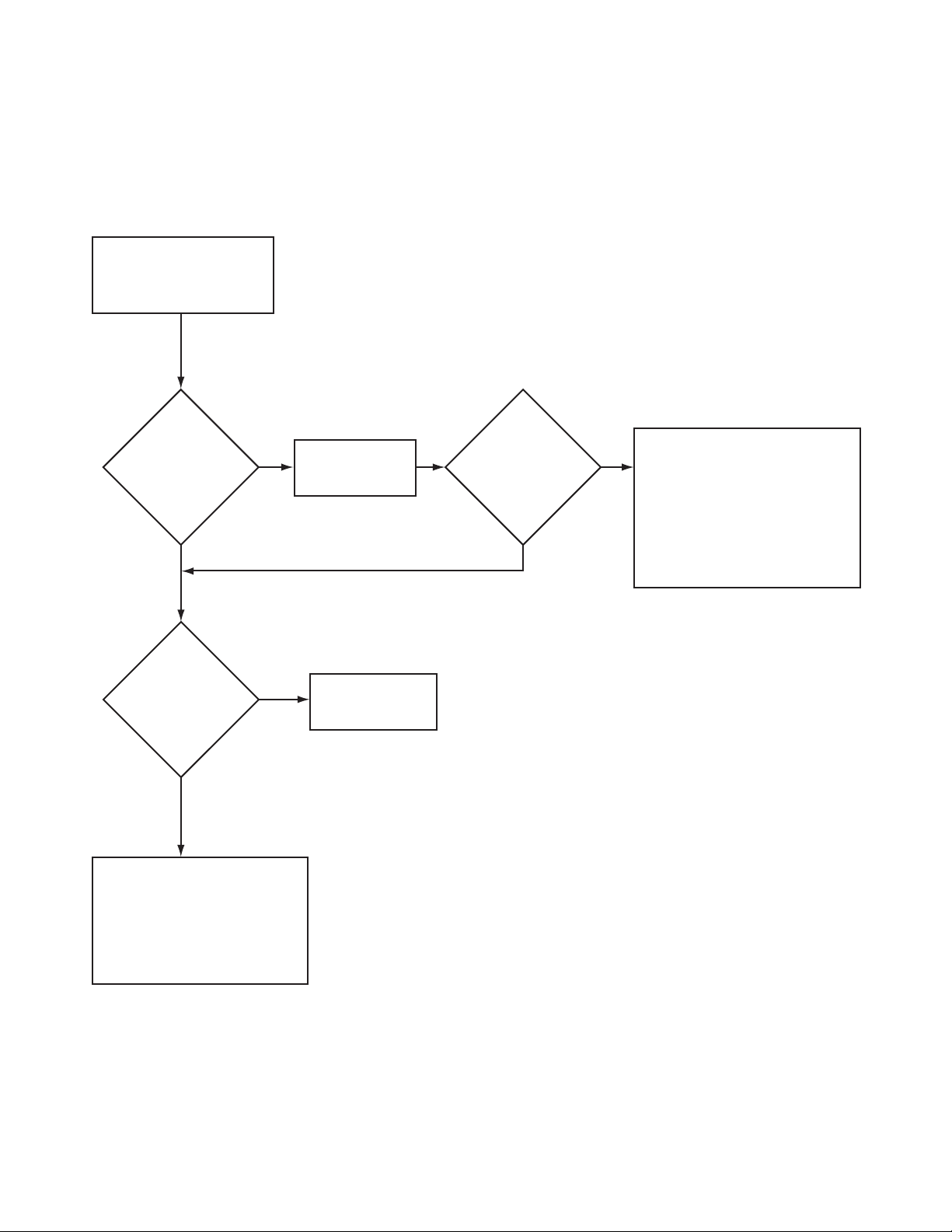
17. TROUBLESHOOTING COIN DROP
When coin is placed into coin slot, the coin should roll down drop and be heard dropping into coin vault. If coin
does not fall into coin vault or if coin drop sensor does not register that coin has been entered, follow
troubleshooting instructions on the following page. Refer to Figure 1 for path that coin follows when working
properly.
IMPORTANT: Never use oil to correct coin drop problems. Oil residue will prevent coins from rolling
properly.
IMPORTANT: Do not bend or damage mechanical parts within coin drop.
Figure 1
37593
© Copyright, Alliance Laundry Systems LLC – DO NOT COPY or TRANSMIT
15
Section 3 Troubleshooting
YES
Refer to wiring diagram
for proper connections.
Replace
coin drop
NO
Is proper
electrical power
supplied to coin
drop? (Incorrect
electrical connection may
prevent coins from
registering in
coin drop.)
YES
Refer to Paragraph 63
for instructions on
cleaning drop.
NO
Is coin drop
clean? (Residue
or lint build-up may
prevent coins from
following through
required check
stages of
drop.)
YES
Refer to Installation
Instructions for instructions
on leveling machine.
NO
Is machine
level? (Machines
that aren't level may
prevent coins from
following through
required check
stages
of drop.)
TLW305S
TROUBLESHOOTING COIN DROP
16
© Copyright, Alliance Laundry Systems LLC – DO NOT COPY or TRANSMIT
37593
To reduce the risk of electric shock, fire, explosion, serious injury or death:
• Disconnect electric power to the washer before servicing.
• Never start the washer with any guards/panels removed.
• Whenever ground wires are removed during servicing, these ground wires must be
reconnected to ensure that the washer is properly grounded.
W003
WARNING
Troubleshooting
Electronic Control Models
18. ERROR CODE LISTING E:00 General Error
E:01 Proximity Error Micro-wand IIIe is improperly aimed at infrared communicator (angle or
distance): Re-aim Micro-wand IIIe.
E:02 IR Communications
Disconnection
E:05 Invalid Value
Communication
E:07 Inoperative Control Replace electronic control.
E:08 Inoperative Control Replace electronic control.
E:09 Proximity Error Micro-wand IIIe is improperly aimed at infrared communicator (angle or
E:0A Proximity Error Micro-wand IIIe is improperly aimed at infrared communicator (angle or
E:0B IR Communication
Disconnection
E:0C IR Communication
Disconnection
E:0d Pressure Switch Error 1. Check fill and drain hoses for improper installation and kinks.
E:0F IR Communicator
Programmed Off
Micro-wand IIIe prematurely pulled away from electronic control during
infrared communication: Maintain infrared connection between Microwand IIIe and electronic control duri ng commu nic at ion.
Invalid code downloaded from Micro-wand IIIe to electronic control.
distance): Re-aim Micro-wand IIIe.
distance): Re-aim Micro-wand IIIe.
Micro-wand IIIe prematurely pulled away from electronic control during
infrared communication: Maintain infrared connection between Microwand IIIe and electronic control duri ng commu nic at ion.
Micro-wand IIIe prematurely pulled away from electronic control during
infrared communication: Maintain infrared connection between Microwand IIIe and electronic control duri ng commu nic at ion.
2. Check fill electrical circuit: Replace inoperative switches or wires.
Reprogram infrared communicator on.
Err Coin Error 1. Inoperative coin sensor: Run the Coin Drop Diagnostic test.
2. Coin drop obstruction: Check coin drop area and remove any
obstructions.
3. Customer tampering: Evaluate security procedures.
NOTE: Disconnecting power to the unit may clear the error display.
37593
© Copyright, Alliance Laundry Systems LLC – DO NOT COPY or TRANSMIT
17

Section 3 Troubleshooting (Electronic Control Models)
NOTE: If replacing an inoperati ve electronic contr ol due to burnt pin(s) on th e 6-pin wire harness con nector
block, it may be due to damaged terminals in the harness connector. Damaged terminals in the harness
connector will appear burnt or show signs of heat discoloration on the connector block. Replace the control
wire harness with the control to avoid repeated damage.
18
© Copyright, Alliance Laundry Systems LLC – DO NOT COPY or TRANSMIT
37593
Section 3 Troubleshooting (Electronic Control Models)
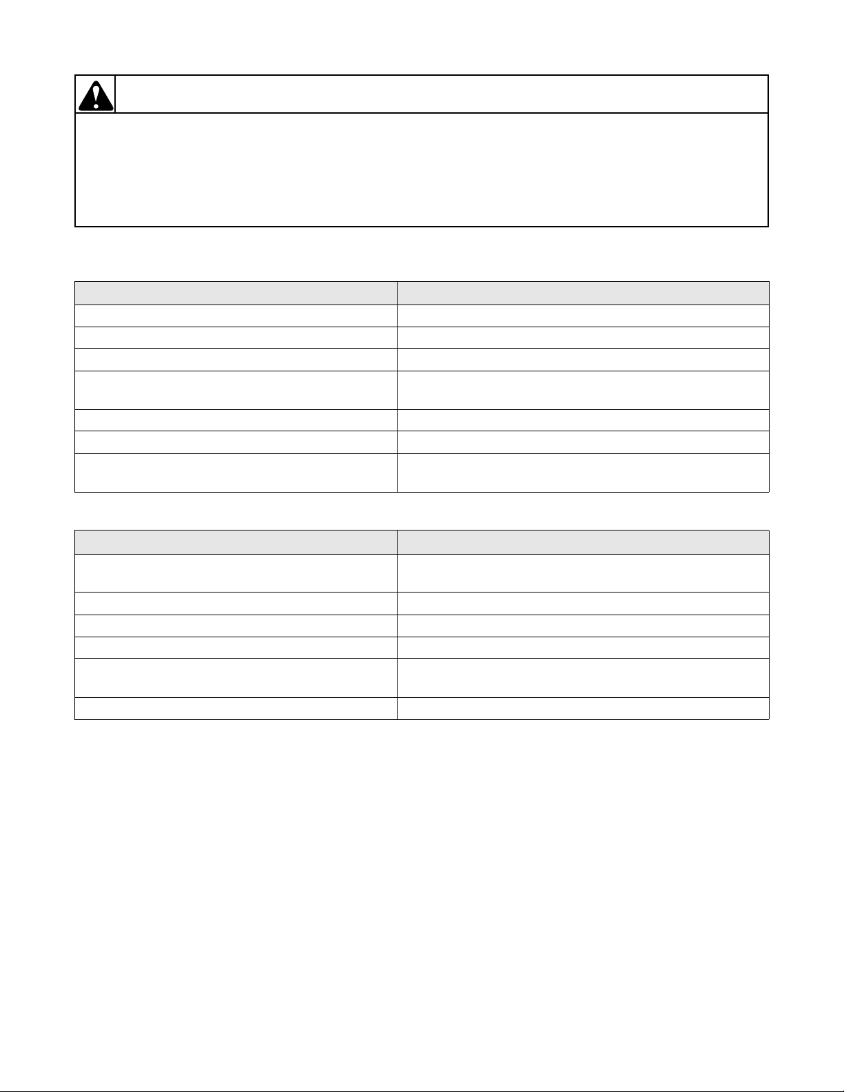
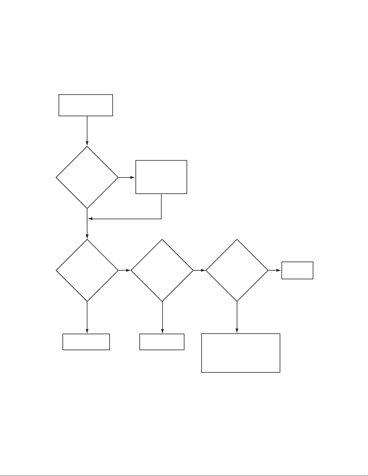
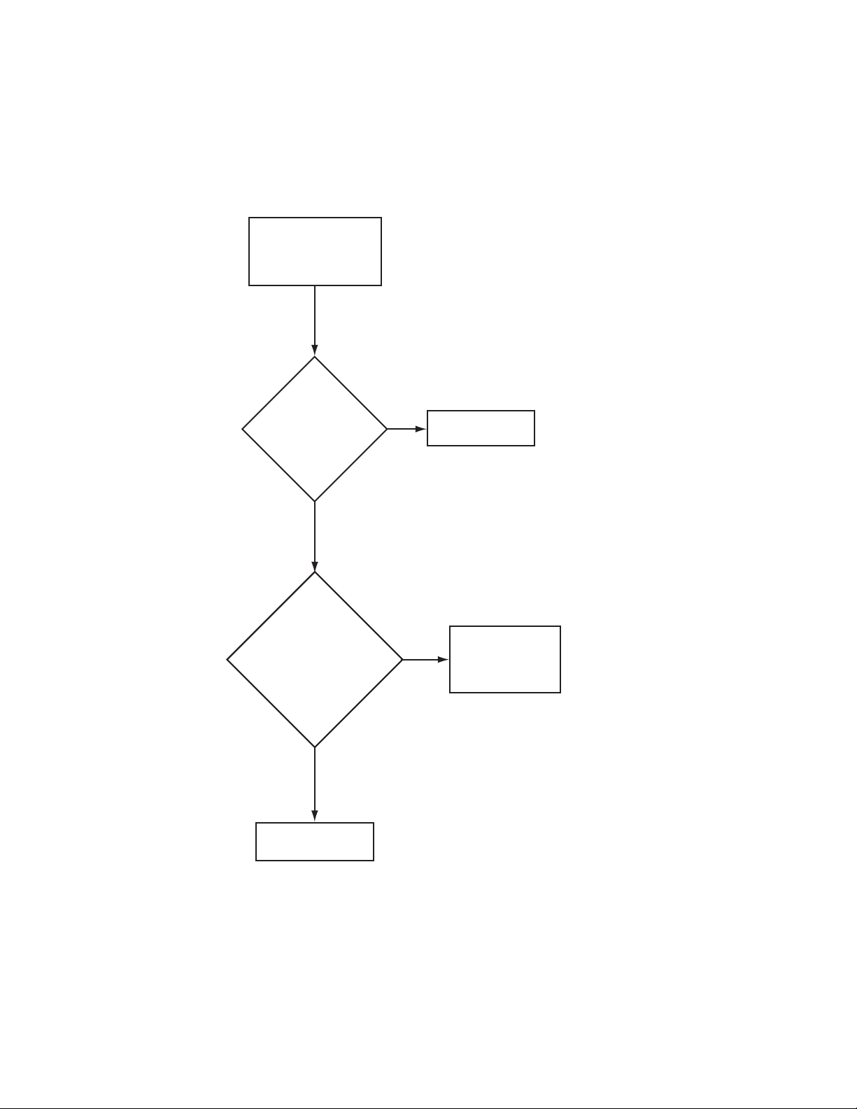
19. CANNOT PERFORM INFRARED COMMUNICATION
Attempt to communicate
with the electronic control
from the Micro-wand.
Is
there any
acknowledgement
of any kind from
the electronic
control?
YES
Does
the electronic
control display
"E:OF" or
"– C–" ?
"E:OF"
Check the following:
– (IR) disabled by manual prog.
– Is the (IR) on the control
covered or blocked?
– If needed, change electronic
control board.
NO NO
"– C–"
Aim Micro-wand
closer and try
again.
Communication
sequence checks
out.
Is
there any
control
response?
YES
Check the following:
– Low battery on Micro-wand.
– Is the (IR) on the control
covered or blocked?
– If needed, replace electronic
control board.
– Is the (IR) cap properly
attached to the Micro-wand?
W367S
37593
© Copyright, Alliance Laundry Systems LLC – DO NOT COPY or TRANSMIT\
19
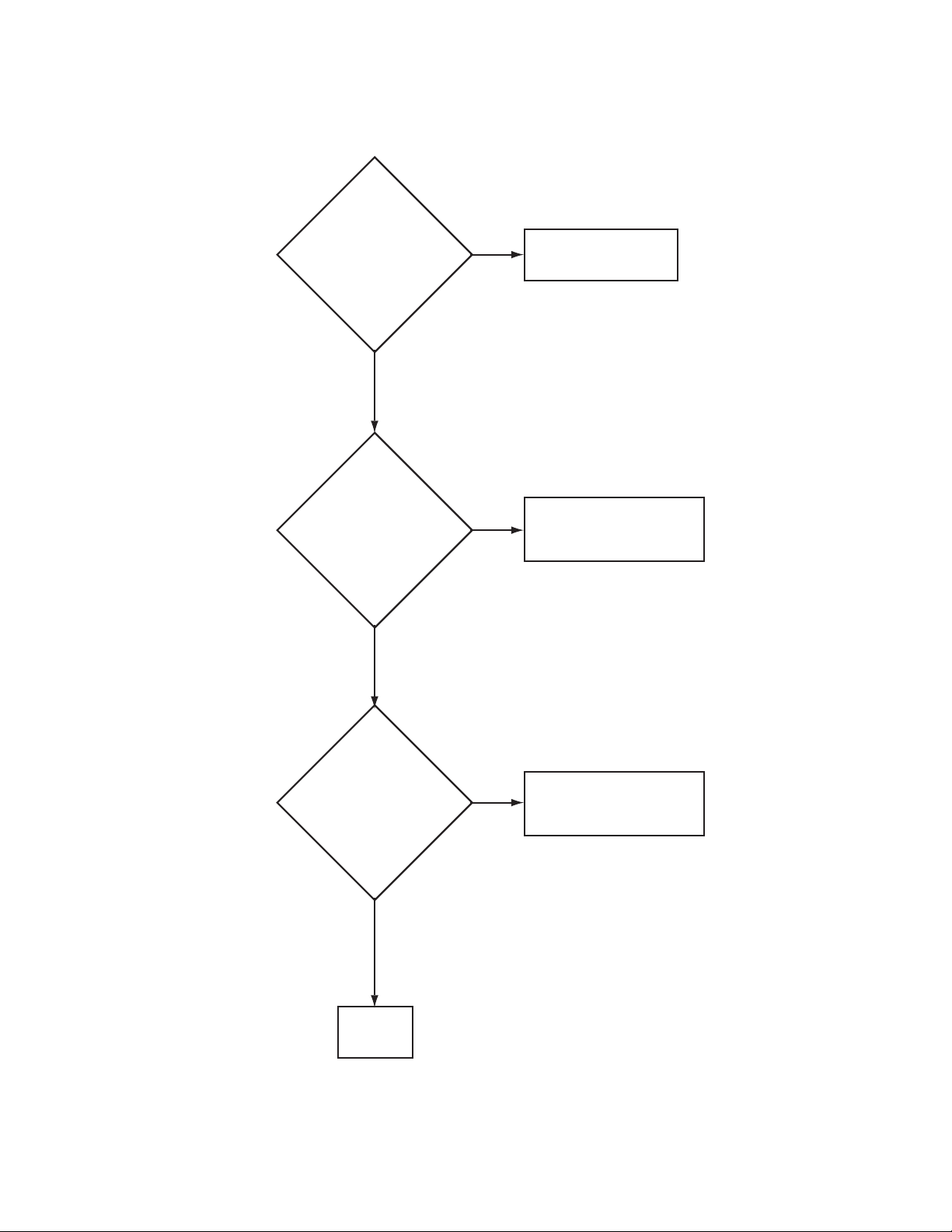
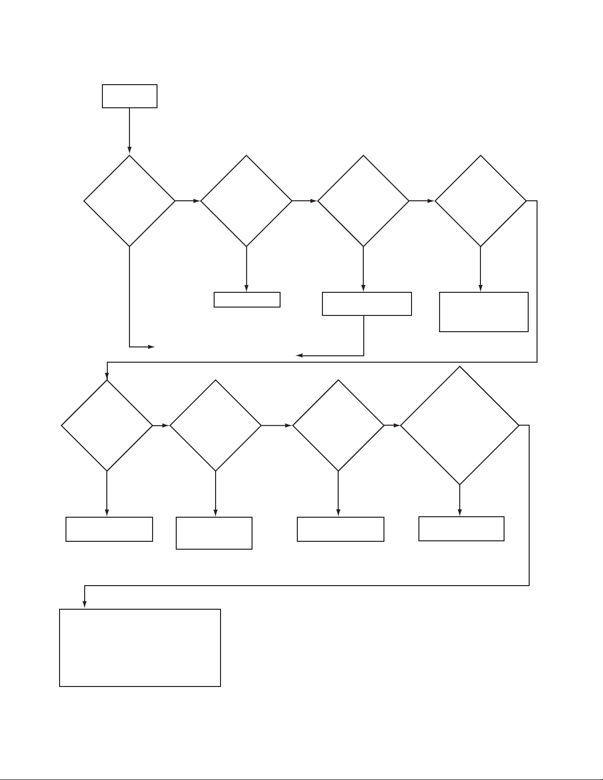
Section 3 Troubleshooting (Electronic Control Models)
Start coin drop
diagnostic test.
Enter several coins.
Replace
coin drop.
Reconnect and
run test again.
Reconnect and
run test again.
Open
control
panel
Check
coin
drop
Make sure the
control is reset
properly and
prompting for a
vend.
NOTE: In this section, bring the
control out of the diagnostic mode.
Also, make sure the control is not
in a free vend mode.
NOTE: Inspect and test for continuity
the harness between the drop
and electronic control board.
NO
NO NO
Retest again, if not successful
the following is the problem:
– Replace coin drop.
If the problem still exists:
– Replace electronic control.
NO
YES
YES YES YES
Does
the electronic
control display
coin counter
increment
properly?
Is
connection
"H2" firmly seated
in its receptacle
on the
control?
Is
the 3-pin
connector plug
firmly seated in
its receptacle?
Are
wires exiting
the coin drop
optical sensor
cracked or
broken?
W368S
NOTE: For instructions on performing tests,
refer to programming manual.
20. COINS IGNORED WHEN ENTERED
20
© Copyright, Alliance Laundry Systems LLC – DO NOT COPY or TRANSMIT
37593

Section 3 Troubleshooting (Electronic Control Models)
The electronic control has
no LED or VFD functioning
on the control board.
Replace electronic
control.
Open
control
panel
Plug electronic
control unit into
electrical outlet.
YES
YES
Disconnect power and check for
broken, loose, or incorrect wiring from
the electrical outlet to the electronic
control.
NOTE: This voltage check confirms that
main power is present to the control.
NO
NO
Is the
power cord
plugged in?
Is there
voltage at "FS1"
black to "FS2"
white?
W369S
21. ELECTRONIC CONTROL HAS NO VISIBLE DISPLAY
37593
© Copyright, Alliance Laundry Systems LLC – DO NOT COPY or TRANSMIT\
21
Section 3 Troubleshooting (Electronic Control Models)
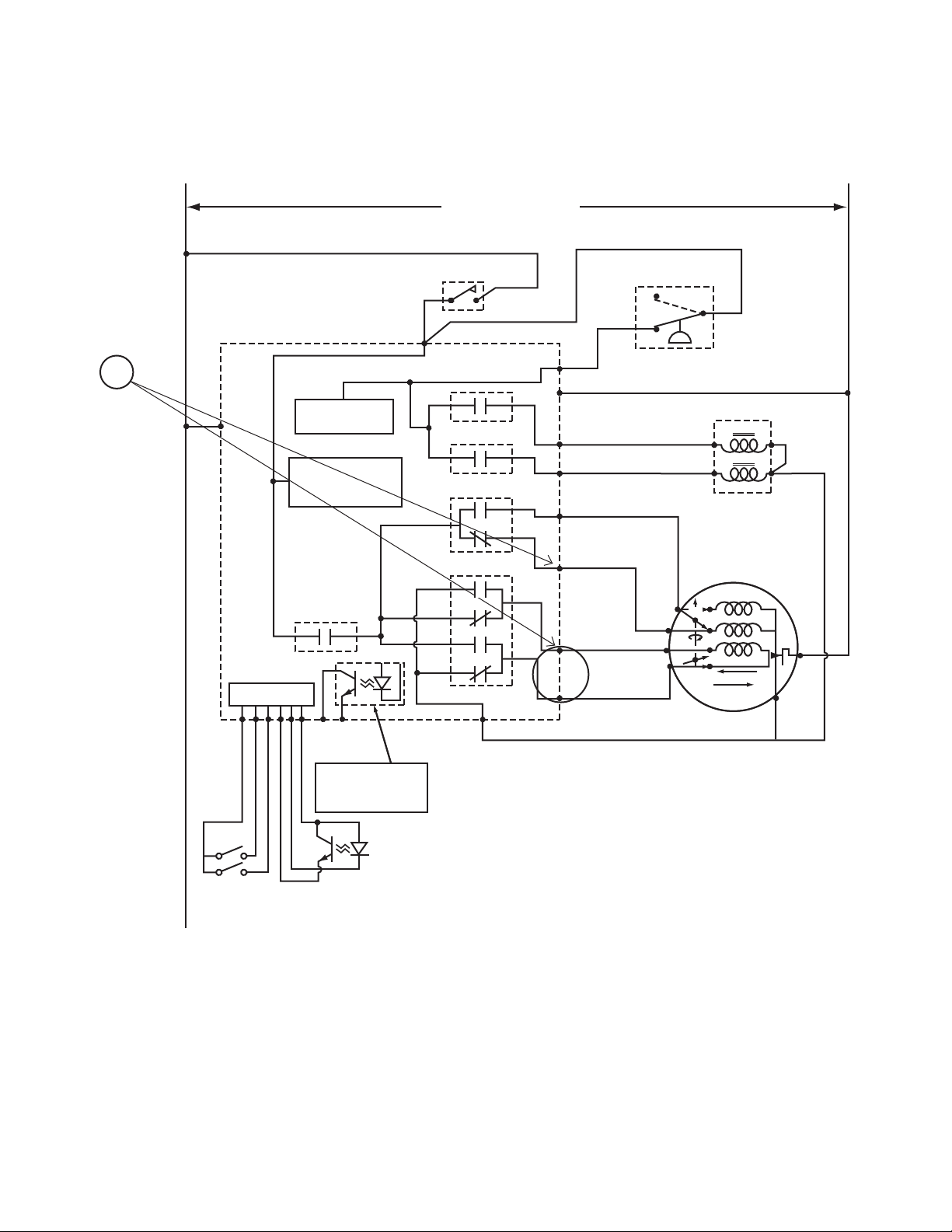
22. NO FILL ANALYSIS
Washer is
not filling.
Is
the display
on?
YES
Are
the water
lines turned
on?
(#) Numbers next to voltage checks
correspond to the locations marked
on the wiring schematic.
Is the
YES YES
coin counter
counting down
as coins are
entered in
the drop?
(1)
Check
voltage at
the lid switch
pnk/blu "COM"
to "H3-3",
is there
voltage?
YES
(2)
Check
voltage at
the pressure
switch "1" PNK/BLU
and to "H3-3",
is there
voltage?
NO
Replace inoperative
wiring.
NONO
Turn on water.
If the problem still exists, refer to
these other troubleshooting guides:
"Electronic control has no visible display",
or "Coins ignored when entered".
(3)
Check
voltage at
YES
the pressure
switch "2" BLU/WHT
and to "H3-3",
is there
voltage?
NO
Replace pressure
switch or
pressure hose.
YES
When checking
voltage to
neutral, check
between source and
"H3-3" since neutral
for mixing values is
through the thermal
protect on the motor.
Replace inoperative
coin drop.
(4)
Check
voltage
at control
"H3-1" to "H3-3",
is there
voltage?
NO
Replace inoperative
wiring.
NO
Open
control
panel
YES
Temps
listed are
determined
by what water
temps have been
selected
NO
After checking for
correct wiring,
replace inoperative
lid switch.
(5)
Voltage
check off
electronic control
board hot - ORG "H5-1"
to "H3-3" cold - GREY,
"H5-4" to "H3-3" warm -
"H5-1" and "H5-4"
to "H3-3",
is there
voltage?
NO
Replace electronic
control board.
YES
On mixing valve check and replace:
– Inlet screens.
– Wiring and connections.
– Replace coils or mixing valve.
– Check thermal protect and wiring
from thermal protect to "H3-3"
22
© Copyright, Alliance Laundry Systems LLC – DO NOT COPY or TRANSMIT
W370S
37593

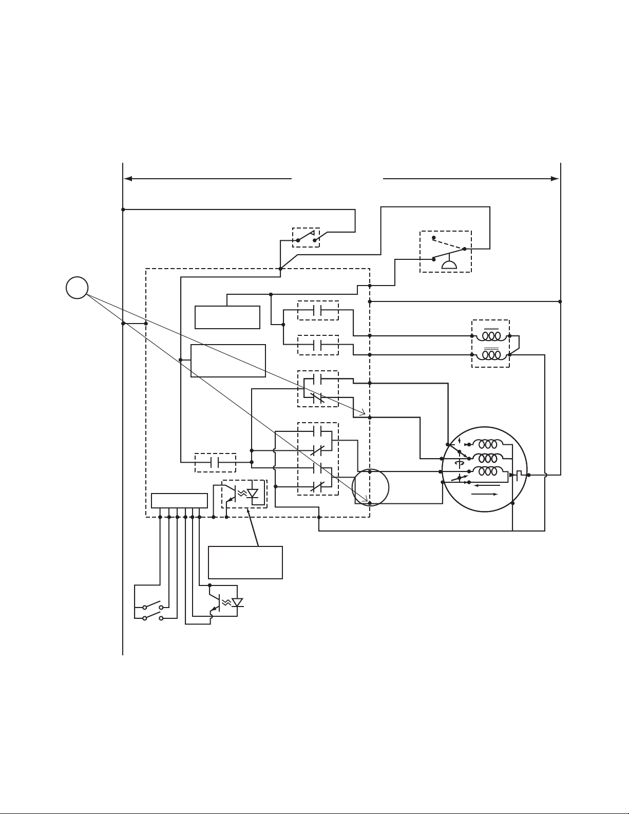
Section 3 Troubleshooting (Electronic Control Models)
LOW
MOTOR
MOTOR SPEED
HOT
COLD
LID AND UNBALANCE SWITCH
ELECTRONIC CONTROL
SCHEMATIC
COLD
MIXING VALVE
PRESSURE SWITCH
PRESSURE SWITCH
AND
WATER CIRCUIT
LID SWITCH SENSE.
MOTOR DIRECTION
AND CONTROL AND
TIMING CIRCUIT
AVAILABLE OUTPUT
TRANSISTOR IS
"OFF" WHEN MACHINE
IS RUNNING
AUDIT CONTROL
CIRCUIT
H3-2
H6-2
H6-1
H3-3
H3-6
H3-4
K3
K5
K4
K2
K1
FS-2
FS-1
N
H3-1
H3-1
L1
L1
N
H3-5
H5-1
H5-4
MOTOR START/DIRECTION
MOTOR MASTER
SERVICE
DOOR
COIN VAULT
COIN DROP
SENSOR
HIGH
START
AGITATE
SPIN
4
6
1
7
3
3
2
1
8
TP
HOT
120 VOLTS A.C. 60 HZ.
H2-1
H2-2
H2-3
H2-5
H2-6
H2-4
3
1
2
5
4
W371S
NO FILL ANALYSIS
37593
© Copyright, Alliance Laundry Systems LLC – DO NOT COPY or TRANSMIT\
23
Section 3 Troubleshooting (Electronic Control Models)
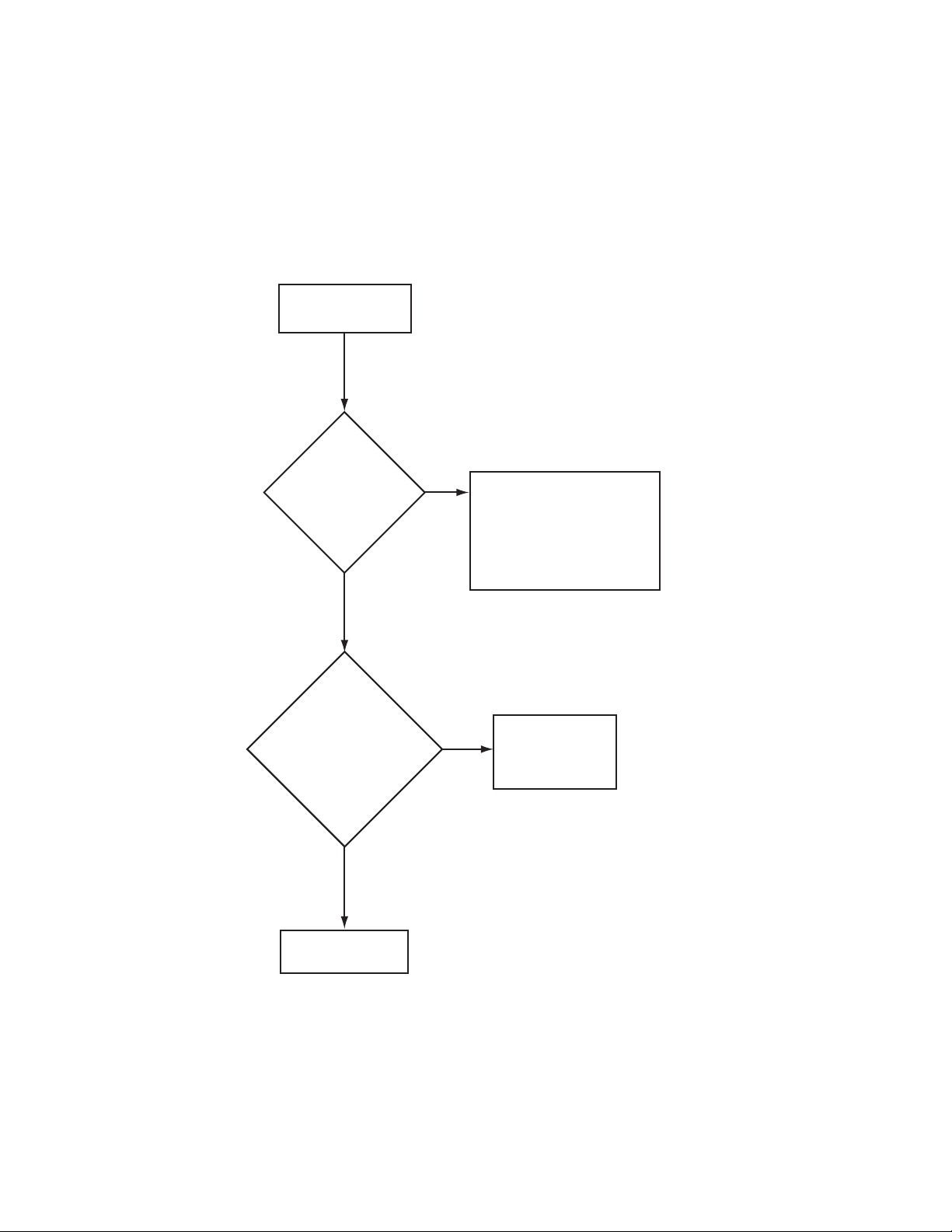
23. NO MOTOR RUN — AGITATE ANALYSIS
The wash tub has
been filled and
there is no motor
run for agitate.
washer lid
closed?
Open
control
panel
(1)
voltage at
electronic
control board
BLU "H3-4" to "H3-2"
RED "H3-6" to BRN
"H3-2" is there
voltage?
Is the
Check
YES
(#) Numbers next to voltage checks
correspond to the locations marked
on the wiring schematic.
NOTE: All checks in this flow chart
are based on the assumption a
high speed agitate and spin cycle
have been selected.
NO
YES
Close washer
lid.
After checking
for correct wiring,
refer to Section 7
or Paragraph 6.
24
NO
Replace electronic
control board.
W372S
© Copyright, Alliance Laundry Systems LLC – DO NOT COPY or TRANSMIT
37593
Section 3 Troubleshooting (Electronic Control Models)
NO MOTOR RUN — AGITATE ANALYSIS
L1
L1
ELECTRONIC CONTROL
1
FS-1
L1
L1
AUDIT CONTROL
AUDIT CONTROL
CIRCUIT
CIRCUIT
ELECTRONIC CONTROL
PRESSURE SWITCH
PRESSURE SWITCH
AND
AND
WATER CIRCUIT
WATER CIRCUIT
LID SWITCH SENSE.
LID SWITCH SENSE.
MOTOR DIRECTION
MOTOR DIRECTION
AND CONTROL AND
AND CONTROL AND
TIMING CIRCUIT
TIMING CIRCUIT
MOTOR MASTER
MOTOR MASTER
K4
K4
120 VOLTS A.C. 60 HZ.
LID AND
UNBALANCE SWITCH
H3-1
H3-1
COLD
COLD
HOT
HOT
MOTOR SPEED
MOTOR SPEED
MOTOR START/DIRECTION
MOTOR START/DIRECTION
PRESSURE SWITCH
PRESSURE SWITCH
3
3
2
2
H3-1
N
FS-2
K1
K1
K2
K2
K5
K5
K3
K3
FS-2
H5-4
H5-4
H5-1
H5-1
H3-5
H3-5
H3-4
H3-4
H3-6
H3-6
H3-2
H3-2
1
1
MIXING VALVE
MIXING VALVE
COLD
COLD
HOT
MOTOR
3
7
LOW
HIGH
1
6
START
AGITATE
TP
SPIN
N
N
4
8
37593
H2-4
SERVICE
SERVICE
DOOR
DOOR
COIN VAULT
COIN VAULT
H3-3
H2-6
H2-5
H6-1
H6-1
H2-1
H2-2
H2-3
AVAILABLE OUTPUT
AVAILABLE OUTPUT
"OFF" WHEN MACHINE
"OFF" WHEN MACHINE
H6-2
TRANSISTOR IS
TRANSISTOR IS
IS RUNNING
IS RUNNING
COIN DROP
COIN DROP
SENSOR
SENSOR
H3-3
SCHEMATIC
SCHEMATIC
© Copyright, Alliance Laundry Systems LLC – DO NOT COPY or TRANSMIT\
W373S
25
Section 3 Troubleshooting (Electronic Control Models)
The washer will
not spin.
Replace electronic
control board.
Open
control
panel
1) Open lid and close
to reset switch.
2) Check lid/unbalance
switch correct wiring.
3) Possible thermal overload
on motor.
NO
NO
YES
YES
Is the
"unbalance"
indicator flashing
on the electronic
control?
(1)
Check
voltage at
electronic control
board
BLU "H3-4" to "H3-6"
BRN "H3-2" to "H3-6",
is there
voltage?
W374S
NOTE: All checks in this flow chart
are based on the assumption a
high speed agitate and spin cycle
have been selected.
(#) Numbers next to voltage checks
correspond to the locations marked
on the wiring schematic.
After checking
for correct wiring,
refer to Section 7
or Paragraph 6.
24. NO MOTOR RUN — SPIN ANALYSIS
26
© Copyright, Alliance Laundry Systems LLC – DO NOT COPY or TRANSMIT
37593
Section 3 Troubleshooting (Electronic Control Models)
NO MOTOR RUN — SPIN ANALYSIS
L1
L1
ELECTRONIC CONTROL
1
FS-1
L1
L1
AUDIT CONTROL
AUDIT CONTROL
CIRCUIT
CIRCUIT
ELECTRONIC CONTROL
PRESSURE SWITCH
PRESSURE SWITCH
AND
AND
WATER CIRCUIT
WATER CIRCUIT
LID SWITCH SENSE.
LID SWITCH SENSE.
MOTOR DIRECTION
MOTOR DIRECTION
AND CONTROL AND
AND CONTROL AND
TIMING CIRCUIT
TIMING CIRCUIT
MOTOR MASTER
MOTOR MASTER
K4
K4
120 VOLTS A.C. 60 HZ.
LID AND
UNBALANCE SWITCH
H3-1
H3-1
COLD
COLD
HOT
HOT
MOTOR SPEED
MOTOR SPEED
MOTOR START/DIRECTION
MOTOR START/DIRECTION
PRESSURE SWITCH
PRESSURE SWITCH
3
3
2
2
H3-1
N
K1
K1
K2
K2
K5
K5
K3
K3
FS-2
H5-4
H5-1
H3-5
H3-5
H3-4
H3-4
H3-6
H3-6
H3-2
H3-2
1
1
MIXING VALVE
MIXING VALVE
COLD
COLD
HOT
MOTOR
MOTOR
LOW
3
3
7
7
1
1
6
6
LOW
HIGH
HIGH
START
START
AGITATE
AGITATE
SPIN
SPIN
TP
TP
N
N
4
8
37593
H2-4
SERVICE
SERVICE
DOOR
DOOR
COIN VAULT
COIN VAULT
H3-3
H2-6
H2-5
H6-1
H6-1
H2-1
H2-2
H2-3
AVAILABLE OUTPUT
AVAILABLE OUTPUT
"OFF" WHEN MACHINE
"OFF" WHEN MACHINE
H6-2
TRANSISTOR IS
TRANSISTOR IS
IS RUNNING
IS RUNNING
COIN DROP
COIN DROP
SENSOR
SENSOR
H3-3
SCHEMATIC
SCHEMATIC
© Copyright, Alliance Laundry Systems LLC – DO NOT COPY or TRANSMIT\
W375S
27
 Loading...