

Page 1
FOR ALL 1/8
OFF-ROAD
& TRUGGY
®
Page 2

2
CONTENTS
Introduction 3
Equipment and Tools 4
Set-up System Components 4
Tools and Equipment 5
Assembling and Installing the Set-up Stands 7
Assembling the Set-up Stands 7
Assembling the Set-up Board 8
Installing the Set-up Stands 8
Overview of Car Set-up 9
Downstops 10
Effects of Downstop Adjustment 10
Measuring Downstops 10
Adjusting Downstops 11
Ride Height 12
Effects of Ride Height Adjustment 12
Measuring Ride Height 12
Adjusting Ride Height 13
Camber 14
Effects of Camber Adjustment 14
Measuring Camber 14
Adjusting Camber 16
Track-width 14
Effects of Track-width Adjustment 16
Measuring Track-width 16
Adjusting Track-width 17
Caster 18
Effects of Caster Adjustment 18
Measuring Front Caster 18
Adjusting Front Caster 19
Toe 20
Effects of Toe Adjustment 20
Measuring Toe 20
Adjusting Toe 21
Steering 22
Ackermann 22
Servo Saver Preload 23
Bump Steer 23
Roll Center 24
Front Roll Center 24
Rear Roll Center 25
Shock Absorbers 26
Shock Damping 26
Shock Pistons 26
Shock Oil 27
Shock Springs 27
Shock Mounting Position 28
Shock Preload 28
Kick-up (Front) 29
Effects of Front Kick-up Adjustment 29
Adjusting Front Kick-up 29
Anti-squat (Rear) 30
Effects of Rear Anti-squat Adjustment 30
Adjusting Rear Anti-squat 30
Wheelbase 31
Effects of Wheelbase Adjustment 31
Adjusting Wheelbase 31
Anti-roll Bars 32
Effects of Anti-roll Bar Adjustment 32
Adjusting Anti-roll Bars 32
Rear Wing 33
Effects of Rear Wing Adjustment 33
Adjusting the Rear Wing 33
Clutch 34
Clutch Springs 34
Clutch Shoe Orientation 34
Differentials 35
Differential Oil 35
Differential Gears 36
Optional Differentials (XRAY Active Diff™) 36
Gearing 37
Primary Drive Ratio 37
Gear Mesh Adjustment 37
Wheels, Tires and Inserts 37
Recommended Chemicals for Off-road Cars 39
Page 3

3
INTRODUCTION
Top-competition off-road cars/truggies are precision racing machines that feature multiple
adjustments that allow you to set up for any track condition. Most modern off-road cars/
truggies include innovative set-up features that allow you to change adjustments quickly
to achieve a full range of adjustment.
The HUDY Off-road Set-up Book describes how to adjust your off-road car/truggy to suit
your driving style. For each individual set-up area, we describe the effects of changing
the adjustment and how to make the adjustment.
When setting up the car/truggy it is very impor tant that the car sits on an ultra-fl at surface.
We strongly recommend using high-quality HUDY professional set-up tools – including
an ultra-fl at set-up board and marking decal – for every set-up adjustment.
The Basic Set-Up Sheet for your vehicle is always a very good overall starting point. After
rebuilding the chassis, or in case you become lost with your set-up, always return to the
basic starting set-up. If you choose to experiment with set-up, make small adjustments
one at a time, and see if you fi nd any improvement with each adjustment. We strongly
advise you to record and keep track of your set-up changes, record which set-ups work
best at different racetracks under various conditions.
If you own an XRAY model racing car then you can use blank XRAY Set-Up Sheets to
record your data and set-ups or use the unique Virtual Online Database set-up sheets at
www.teamxray.com where you can upload and share your set-up sheets or search for
other set-up sheets posted by factory team drivers or search particular set-up for your
track. The XRAY Virtual Online Database features thousands of set-up sheets and is the
world’s most unique set-up sheet source for your reference.
IMPORTANT!
The adjustment possibilities and methods of adjustment shown in this HUDY Off-road
Set-up Book are particular to the XRAY XB808 1/8 off-road nitro buggy. The general
theory behind the adjustments applies to all off-road vehicles, though the manner in
which the measurements and adjustments are made may differ on other vehicles. Some
of the off-road cars may not have possibility for some adjustments or may require use of
some other optional parts to be able to per form some of the set-up adjustments. Always
refer to the original manufacturer’s documentation for explicit instructions on how to
make set-up adjustments.
Page 4
4
EQUIPMENT AND TOOLS
When setting up, operating and maintaining your off-road car or truggy, we strongly
recommend using high-quality professional HUDY set-up equipment and tools.
SET-UP SYSTEM COMPONENTS
#108805 Exclusive Alu Set-Up System
For All 1/8 Off-road Cars & Truggies
•
CNC-machined alu. and acrylic components
• fully ball-bearing equipped
• precision engraving
• directly measures camber, camber rise,
caster, toe, steering throw symmetry
• easy one-screw assembly/disassembly
#107703 Droop Gauge Support Blocks
• CNC-machined high-grade aluminum
• precision engraving
• supports chassis when checking
downstops
• extra-high 30mm blocks for 1/8 off-road
cars & truggies
• used with 107717 Droop Gauge
#107717 Droop Gauge
• CNC-machined high-grade aluminum
• precision engraving
• measures downstops for off-road
vehicles when used 107703 Droop
Gauge Support Blocks
#108202 Set-Up Board
• exceptionally fl at, warp-resistant
surface
• lightweight, easy to carry
• provides perfectly fl at reference surface
for chassis set-up
• must be used for any set-up
adjustments
#108212 Set-Up Board Decal
• self-adhesive set-up decal for 108202
Set-Up Board
• accurate, clear markings for adjustment
of 1/8 Off-road cars & truggies
• tough, smooth, liquid-resistant plastic
surface
• used for track width adjustment and
checking
#108860 Alu Nuts for Set-up System
• CNC-machined alu nuts for quick &
easy attachment of set-up system plates
to wheel axles
#108841 Truggy Upside Measure Plate
• CNC-machined upside measure plate
(toe plate) for setting up 1/8 truggies
• made of high-quality, tough acrylic
plastic
• precision engraved markings for instant,
reliable readings
• used for the adjustment of: camber &
camber rise, caster, front and rear toe,
steering throw symmetry
• must be used with the #108805 Set-up
System
Page 5
5
TOOLS & EQUIPMENT
Turnbuckle Wrenches
• precision turnbuckle wrenches designed
exclusively by HUDY from special selfdeveloped, world-renown HUDY Spring
Steel™ to ensure maximum strength,
durability, and long life
• additionally hardened to provide
unmatched life span
• wrench head shape is hand-ground on
a precision grinding machine to ensure
a very precise shape to a snug fi t on the
turnbuckle
•
the fork end of the tool is additionally
ground fl at to keep the tool shape as thin as
possible for very easy access in restricted
areas
• available in 3 sizes: 3mm (#181030),
4mm (#181040), and 5mm (#181050)
HUDY Tools
• Allen 1.5 / 2.0 / 2.5mm
(HUDY #111549 / #112049 / #112549)
• Phillips 5.0mm
(HUDY #165049)
• Socket 5.0 / 5.5mm
(HUDY #170058 / #170059)
#182010 Flywheel Tool
• CNC-machined professional Flywheel
Tool off-road and on-road nitro vehicle
clutches
• fl ywheel holder holds all modern RC nitro
car fl ywheels with 2-to-4 pin designs,
allowing you to loosen or tighten the
fl ywheel nut very comfortably and
easily.
• use with 107581 Wrench-Glowplug /
Clutchnut to hold and loosen/tighten
fl ywheel nuts quickly & easily
• other features (including clutch gap
measurement, XCA-style clutchbell
holder) for use with on-road XCA-style
clutches
#107570 Wheel Nut Tool
• CNC-machined hardcoated tool for easy
loosening/tightening 17mm wheel nuts
on 1/8 off-road cars and truggies
• oversized handle gives superior torque
• robust design, machined from one piece
• hard anodized for extra-long lifespan
#107581 Wrench-Glowplug / Clutchnut
• unique, highly-useful combination tool
for nitro racing includes the following:
• 10mm socket wrench for Centax type
fl ywheel nut
• 8mm socket wrench for glowplug
• 5mm hex bit for suspension pivotballs
• extended 8mm glowplug wrench reaches
glowplug even in deep cylinder heads
• made of world-renowned HUDY
Spring Steel™ for highest strength and
durability
• lightweight, perfect-fi t tool
• laser-engraved for easy tool
identifi cation
Page 6
6
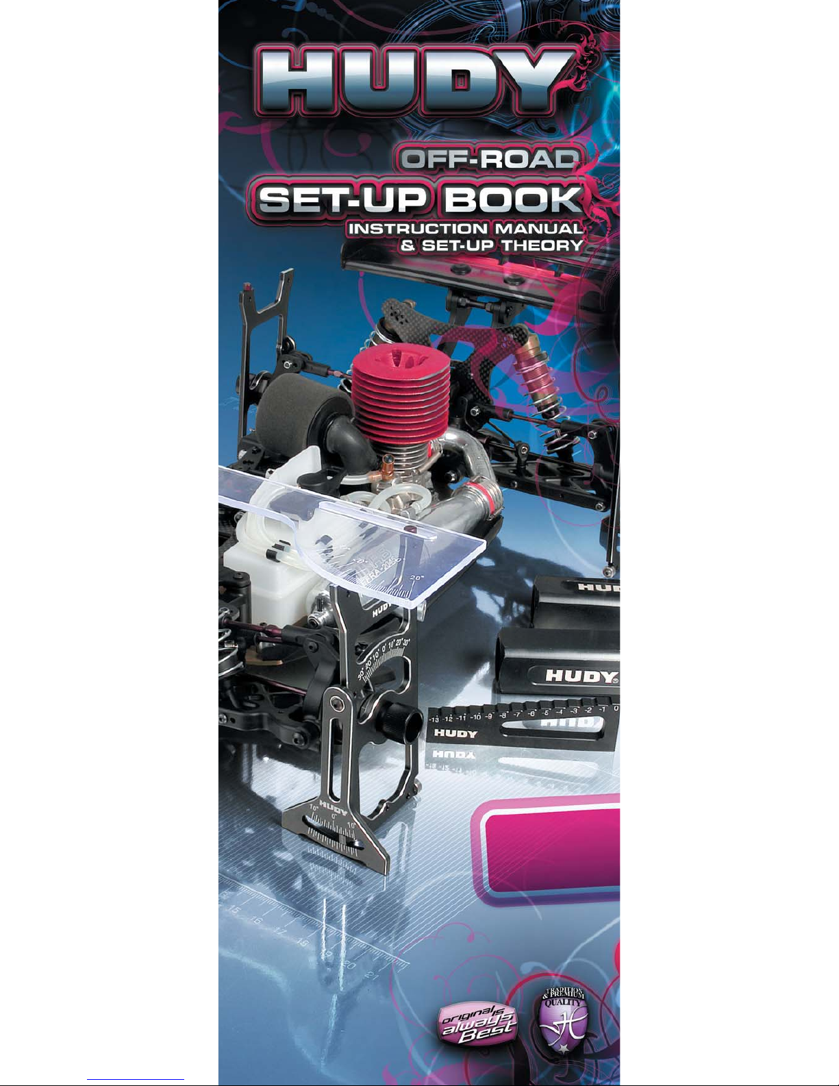
#107610 Exhaust Spring/Caster Clip Remover
• designed to easily and quickly remove
caster clips and exhaust springs
• tip from specially hardened steel
• very light non-slip duraluminum handle
• very durable, long life
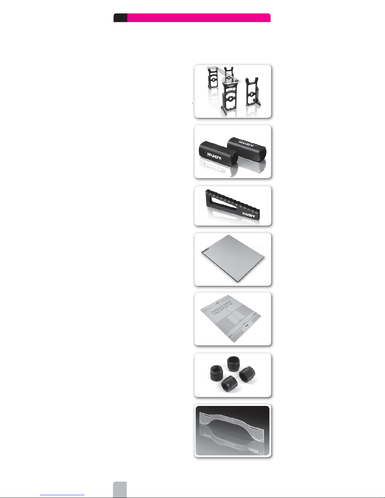
#107600 Reamer For Lexan Bodies
• professional-quality reamer cuts perfect
holes 0-18mm diameter
• exclusive design by HUDY
• very light non-slip duraluminum handle
• special CAD-designed cutting head, handground on specially-modifi ed production
machinery
• perfect & comfor table cutting and use
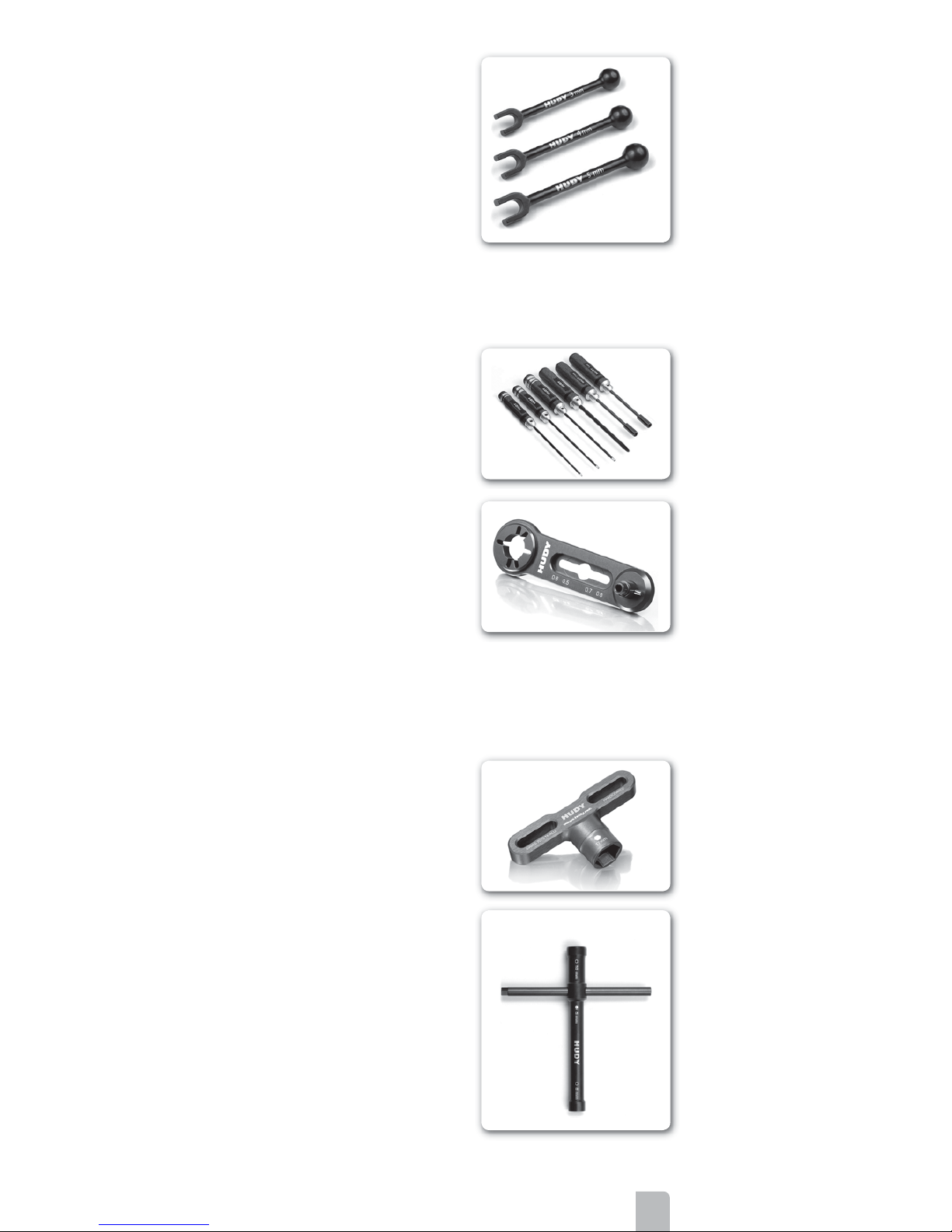
Arm Reamer
• designed specifi cally for RC use, this
arm reamer precisely resizes plastic
holes without creating excessive slop,
allowing you to build a perfect free-moving
suspension
• comfortable molded handle
• quick & easy to use
• available for different size pins: 3.5mm
pins (#107632), 3.0mm pins (#107633),
4.0mm pins (#107634).
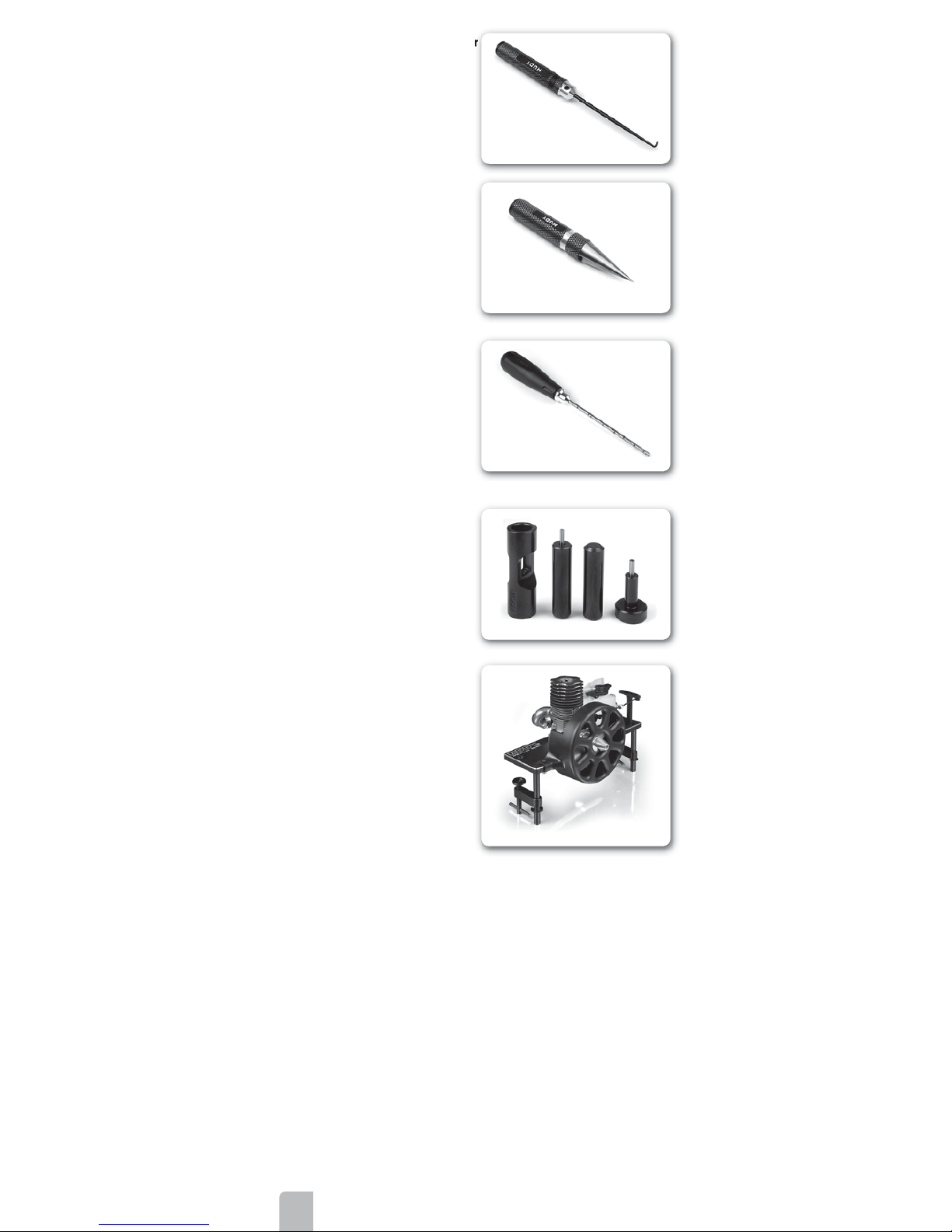
#106000 Drive Pin Replacement Tool
• compact, rugged multi-use tool set for
replacing 3mm drive pins in drive shafts
• heavy-duty construction for long life
• replacement pin sets available separately:
3x14 (#106050)
3x12 (#106051)
3x10 (#106052)
#104140 HUDY Engine Break-In Bench
• the ultimate tool for easy, safe, and
professional break-in of your .12/.15/.21
engine
• suits all bump-start SG crank engines
• allows for a controlled break-in process that
reduces wear & tear on engine components
and increases performance, reliability, and
longevity
• constructed of top-quality components of
tough aluminum and spring steel
• comes partially assembled from the factory
Page 7
7
ASSEMBLING AND INSTALLING THE SET-UP STANDS
When you are measuring and adjusting track-width, camber & camber rise, caster,
toe, steering throw symmetry, and tweak, you will need to assemble and install the
set-up stands.
When you are measuring downstops and ride height, you do not need to use the set-up
stands.
ASSEMBLING THE SET-UP STANDS
The set-up stands of the Exclusive Alu. Set-Up System For All 1/8 Off-road Cars &
Truggies must be assembled in order for you to use them. These stands were designed
for quick and easy “one screw” assembly and disassembly
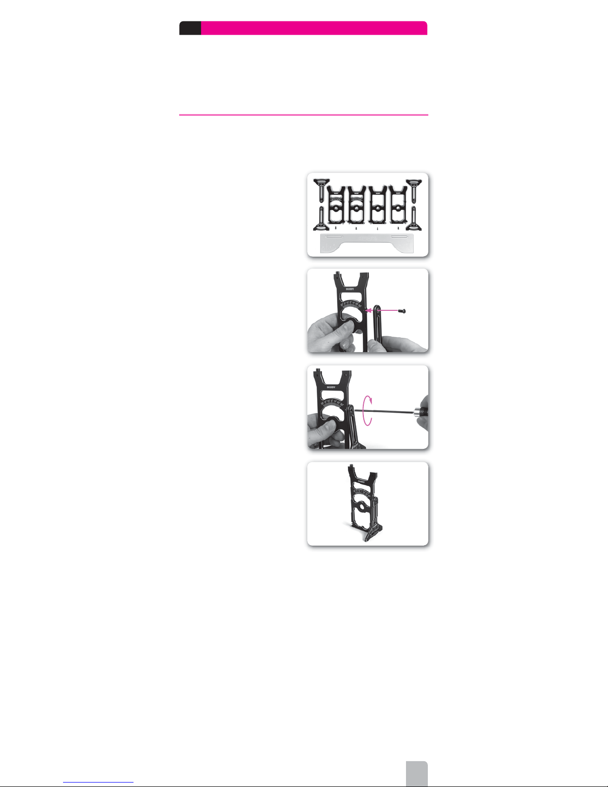
The set-up stands consist of the
following pieces:
• alloy side plates front (2)
• alloy side plates rear (2)
• alloy camber gauges (4)
• acrylic toe gauge (1)
➊ Attach a camber gauge to a side plate
using a screw through the ball-bearing at
the top of the camber gauge.
➋ Using a 2.0mm Allen wrench, tighten
the screw until snug.
➌ Make sure the stand operates freely
without binding.
Page 8
8
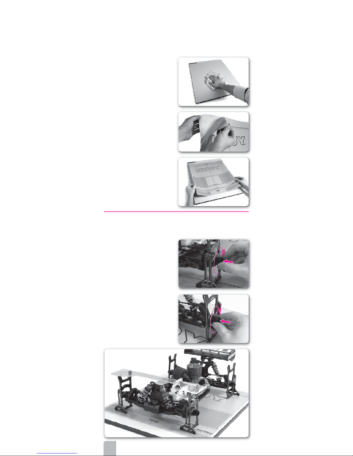
➋
Remove the paper from the rear of the
decal, exposing the adhesive backing.
➌ Center the decal on the board, and
then press the entire decal fi rmly onto the
board.
➍ Rub the decal until it is fl at and
completely adhered to the board.
INSTALLING THE SET-UP STANDS
After you have assembled the four set-up stands, mount them to your car as follows.
➊ Remove the wheels from the car. In
place of the wheels, mount a set-up stand
on each of the four axles. In front use side
plates with scale, while in rear use side
plates without scale (only with HUDY logo).
➋ The camber gauge of each stand
should face outward so it is easy to read.
The camber gauge of the front stand
should face forward, while the camber
gauge of the rear stand should face
rearward.
➌ Place the car (with the mounted set-up
stands) on the set-up board.
FRONT
REAR
ASSEMBLING THE SET-UP BOARD
The completed set-up board consists of the Set-Up Board and the Set-Up Board Decal.
IMPORTANT:
You should always use only the HUDY set-up board when setting up your car with the
HUDY All-In-One Set-Up Solution. This exceptionally fl at, warp-free board will ensure
accurate, precise measurements.
➊ Clean the board with a soft cloth to
remove any debris or contaminants.
Page 9

9
OVERVIEW OF CAR SET-UP
When setting up your off-road car/truggy, we recommend setting it up in the order
indicated in the table below. The order of the settings has been determined as the most
logical to set up your car/truggy properly and easily. Also, certain settings must be
made before others, as changing one setting will impact another setting.
The table below also lists the set-up components to be used to measure or adjust a
particular setting.
TO MEASURE OR ADJUST USE
Downstops
•
Flat set-up board
• Droop gauge support blocks
• Droop gauge
Ride height
• Flat set-up board
• Droop gauge
Camber
• Flat set-up board
• Droop gauge support blocks
• Assembled set-up stands
Track-width
• Flat set-up board
• Board decal
Caster
• Flat set-up board
• Assembled set-up stands
Toe
• Flat set-up board
• Droop gauge support blocks
• Assembled set-up stands
• Toe gauge
There are several types of suspensions used on RC cars, including pivotball and C-hub
suspensions. Each suspension type has its own way of making adjustments for
downstops, camber, caster, toe, etc. For detailed information on adjusting the settings on
your car, refer to the appropriate set-up manuals for your car.
When setting up your off-road car/truggy, you should always prepare it so it is ready to
run, though without the body. This means you should install all electronics, batteries, and
fi ll the fuel tank (nitro only).
Page 10
10
1.1 DOWNSTOPS
Downstops limit how far the suspension arms travel downward, which determines how
far upward the chassis rises. This affects the car’s handling (due to effects on camber
and roll-center) and the ability of the tires to “follow” the track. The effects may change
with the type of track and/or amount of grip available. Downstops are a very sensitive
adjustment, since they alter weight transfer, and all aspects of chassis performance are
affected: braking, acceleration, jumping, traction and rough track handling.
More suspension travel (lower downstop value) makes the car more responsive but less
stable; it is also typically better on a bumpy track or on a track with slow corners. This
allows the chassis to “pitch” rearward or forward more under acceleration or braking
(respectively), which results in more weight transfer.
Less suspension travel (higher downstop value) makes the car more stable and is
typically better on a smooth track. This prevents the chassis from “pitching” rearward
or forward too much under acceleration or braking (respectively), which results in less
weight transfer.
It is very important to have the same downstop settings on the left and right sides
of the car.
EFFECTS OF DOWNSTOP ADJUSTMENT
FRONT DOWNSTOPS
Higher downstop value
(arm is higher
, less
travel)
• Decreases front chassis upward travel on-throttle
• Less rearward weight transfer
• Better on smooth tracks
• More on-power steering
• More responsive in direction change
Lower downstop value
(arm is lower, more
travel)
• Increases upward chassis travel on-throttle
• More rearward weight transfer
• Increases rear traction on corner exit
• Better on bumpy tracks
REAR DOWNSTOPS
Higher downstop value
(arm is higher
, less
travel)
•
Decreases rear chassis upward travel off-throttle or
under braking
• Less forward weight transfer
• Better on smooth tracks
Lower downstop value
(arm is lower, more
travel)
• Increases rear chassis upward travel off-throttle or
under braking
• Less stable under braking
• Increases steering on corner entry
• Better on bumpy tracks
• More turn-in
MEASURING DOWNSTOPS
INITIAL STEPS SET-UP COMPONENTS
Prepare the car as follows Use the following set-up components
• Shocks: Attach the shocks
• Anti-roll bars: Attach the anti-roll bars
• Wheels: Remove the wheels
• Droop Gauge Support Blocks #107703
• Droop Gauge #107717
• Set-up Board #108202
Page 11
11
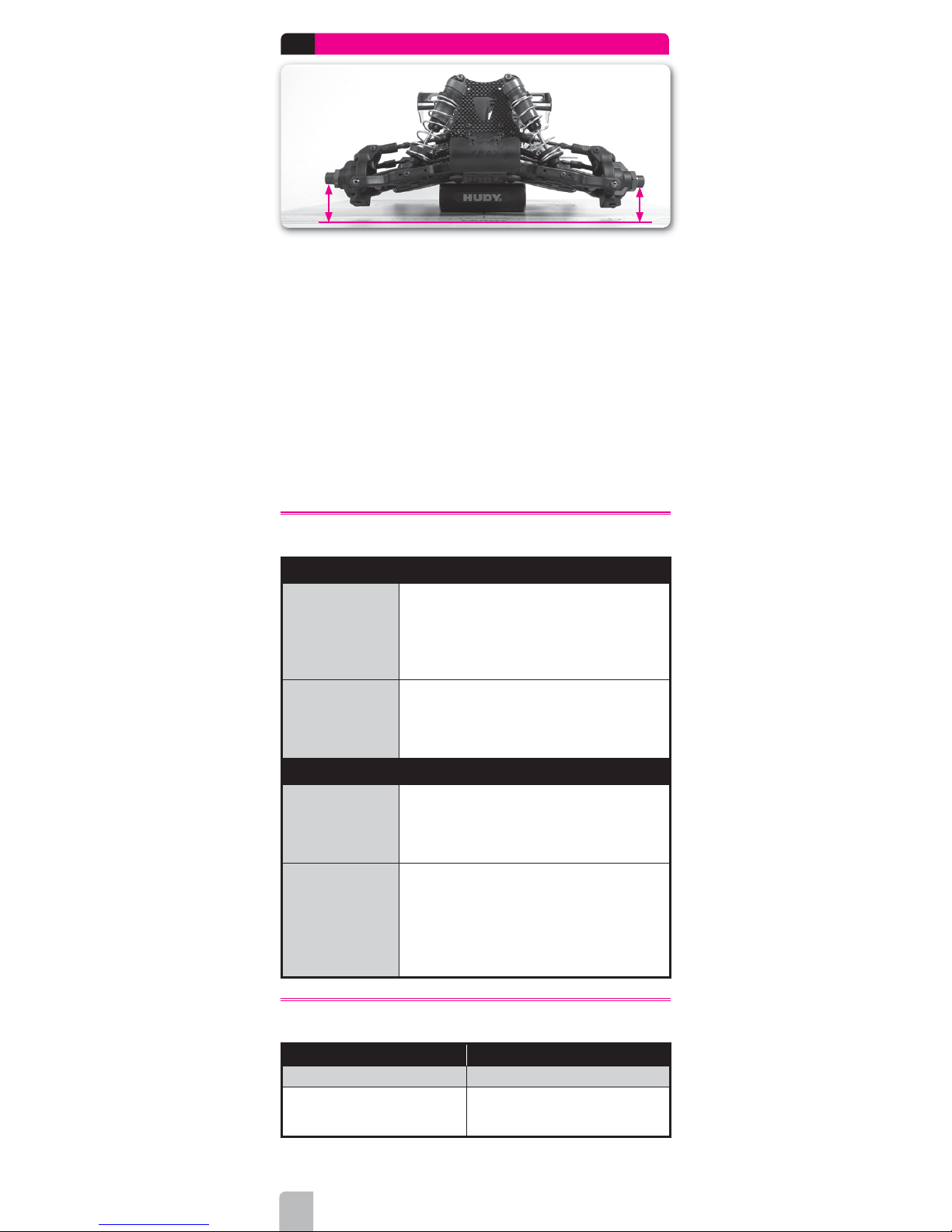
➊ Place the droop blocks on the fl at set-
up board, and then place the fl at part of
the chassis (not the angled part) on the
blocks. Make sure the chassis is solidly
mounted on the support blocks so it does
not move.
➋ Lift and drop the suspension arms so
that they settle in their lowest positions.
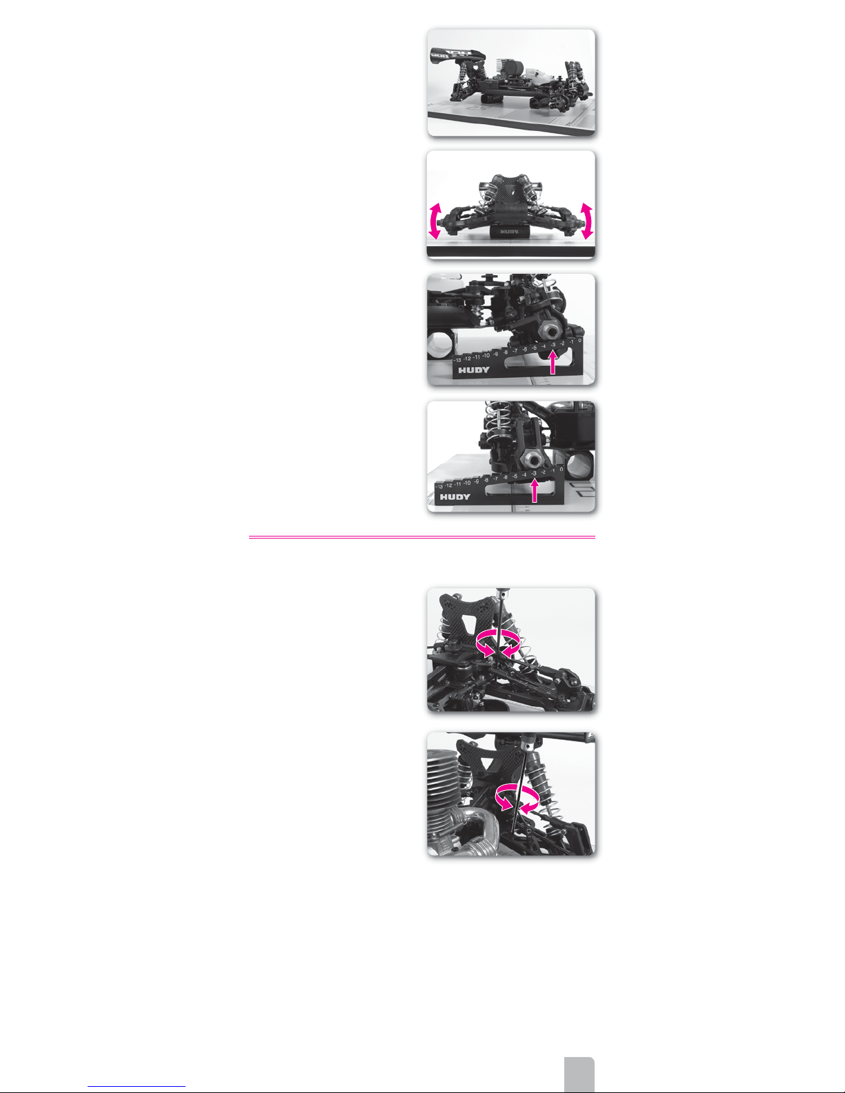
➌ Using the droop gauge, measure the
downstop values at the front and rear of
the car.
FRONT DOWNSTOPS:
Measure the front downstop values under
the round part of the front wheel axles. DO
NOT measure under the hex part.
The values shown on the droop gauge
indicate how many millimeters the
suspension drops below the level of the
chassis.
REAR DOWNSTOPS:
Measure the rear downstop values under
the round part of the rear wheel axles. DO
NOT measure under the hex part.
The values shown on the droop gauge
indicate how many millimeters the
suspension drops below the level of the
chassis.
ADJUSTING DOWNSTOPS
FRONT DOWNSTOPS
Increase
Turn IN (or OUT) the front downstop screw
(depending on the car design) so the front
lower arm raises up slightly.
Decrease
Turn OUT (or IN) the front downstop screw
(depending on the car design) so the front
lower arm drops slightly.
REAR DOWNSTOPS
Increase
Turn IN (or OUT) the rear downstop screw
(depending on the car design) so the rear
lower arm raises up slightly.
Decrease
Turn OUT (or IN) the rear downstop screw
(depending on the car design) so the rear
lower arm drops slightly.
IMPORTANT!
Make equal adjustments on both left and right sides of the car.
Page 12
12
1.2
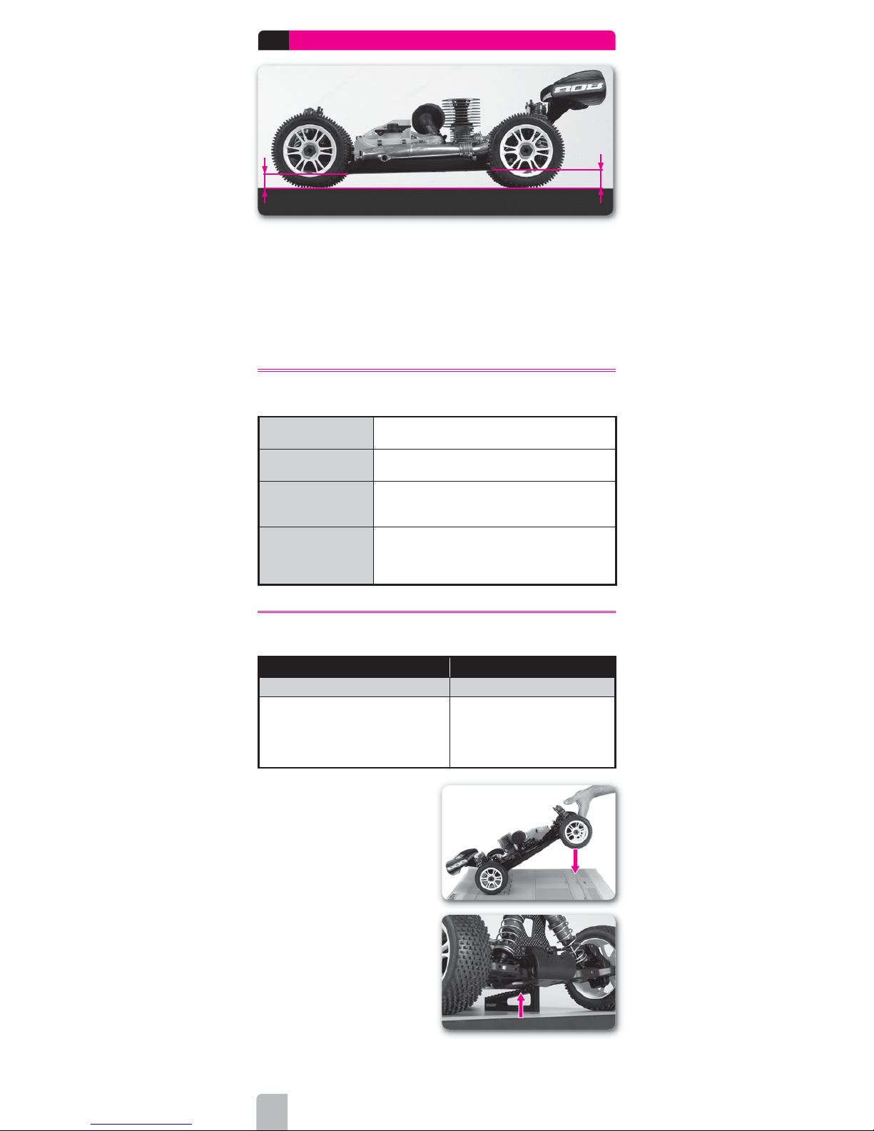
RIDE HEIGHT
front ride height rear ride height
Ride height is the height of the chassis in relation to the surface it is sitting on, with the car
ready to r
un. Ride height affects the car’s traction since it alters the car’s center of gravity
and roll center. Differences in ride height alter the car’s attitude (angle of the chassis)
which in an off-road vehicle can effect how it jumps and lands. Because of changes in
suspension geometry and ground clearance, there are negative consequences to altering
ride height too much.
Ride height is measured with the wheels on the car, and the car ready-to-run. Use the
shock preload collars or clips to raise and lower the ride height.
EFFECTS OF RIDE HEIGHT ADJUSTMENT
Decreasing ride height
• Increases overall stability
• Better on smooth tracks
Increasing ride height
• Decreases overall stability
• Better on bumpy tracks (prevents bottoming)
Front higher than rear
• Increases weight transfer to the rear on-power
• Increases stability
• Decreases steering
Front lower than rear
• Increases weight transfer to front off-power
• Increases steering
• Decreases rear traction
• May cause car to nosedive off jumps
MEASURING RIDE HEIGHT
INITIAL STEPS SET-UP COMPONENTS
Prepare the car as follows
Use the following set-up components
• Shocks: Attach all shocks
• Anti-roll bars: Attach all anti-roll bars
• Wheels: Attach all wheels. Both left and
right wheels at the front or rear should be
the same diameter
• Flat Set-up Board #108202
• Droop Gauge #107717
➊ Place the car on the set-up board.
➋ Lift the front of the car and let it fall back
to the set-up board by itself.
➌ Using the droop gauge, measure the
ride height value at the front of the car.
Page 13

13
➍ Lift the rear of the car and let it fall back
to the set-up board by itself.
➎ Using the droop gauge, measure the
ride height value at the rear of the car.
FRONT RIDE HEIGHT
Place the droop gauge under the front of the chassis (under the FLAT part of the chassis,
not the angled part) and measure the difference between the set-up board and the bottom
of the chassis.
The 0 mark on the droop gauge is equal to 30mm ride height. A negative value on the
droop gauge is lower than the 30mm reference height. For example, if the chassis is at
-3mm on the droop gauge, your ride height is 30-3mm = 27mm.
REAR RIDE HEIGHT
Place the droop gauge under the rear of the chassis (under the FLAT part of the chassis)
and measure the difference between the set-up board and the bottom of the chassis.
The 0 mark on the droop gauge is equal to 30mm ride height. A negative value on the
droop gauge is lower than the 30mm reference height. For example, if the chassis is at
-3mm on the droop gauge, your ride height is 30-3mm = 27mm.
ADJUSTING RIDE HEIGHT
Adjust ride height using spring preload only; DO NOT adjust ride height using downstop
screws.
Your car may use threaded spring preload collars or preload spacers.
Preload setting Threaded preload collar Preload spacers
Increase
TIGHTEN collar so it moves DOWN
the shock body
Use THICKER spacers
above the spring
Decrease
L
OOSEN collar so it moves UP the
shock body
Use THINNER spacers
above spring
FRONT RIDE HEIGHT
Increase
INCREASE preload on both FRONT springs
EQUALLY.
Decrease
DECREASE preload on both FRONT
springs EQUALLY.
REAR RIDE HEIGHT
Increase
INCREASE preload on both REAR springs
EQUALLY.
Decrease
DECREASE preload on both REAR springs
EQUALLY.
Page 14

14
1.3
CAMBER
-
+
r
c
a
m
b
e
Camber is the angle of a wheel to the surface on which the car is resting (with wheels and
shock absorbers mounted).
• Zero degrees (0°) of camber means that the wheel is perpendicular to the reference
surface.
• Negative camber means that the top of the wheel is leaning inwards towards the
centerline of the car.
• Positive camber means that the top of the wheel is leaning outwards from the centerline
of the car.
Camber affects the car’s side traction. Generally more negative (inward) camber means
increased grip since the side-traction of the wheel increases. Adjust front camber so that
the front tires wear fl at. Adjust rear camber so that the rear tires wear slightly conical to
the inside.
The amount of front camber required to maintain the maximum contact patch also depends
on the amount of caster. Higher caster angles (more inclined) require less negative camber,
while lower caster angles (more upright) require more negative camber.
EFFECTS OF CAMBER ADJUSTMENT
FRONT CAMBER
More negative (more inclined)
• More steering
Less negative (less inclined)
• Less steering
REAR CAMBER
More negative (more inclined)
• Decreases rear traction entering and in corners
Less negative (less inclined)
• Increases rear traction entering and in corners up
to a point
• If the shock is too vertical and traction is lost, the
traction will be lost very abruptly and the car will
be hard to control
MEASURING CAMBER
INITIAL STEPS SET-UP COMPONENTS
Prepare the car as follows Use the following set-up components
• Shocks: Attach all shocks
• Anti-roll bars: Detach all anti-roll bars
• Wheels: Remove all wheels
• Flat Set-up Board #108202
• Assembled Set-up Stands #108805
• Droop Gauge Support Blocks #107703
➊ Assemble the set-up stands.
➋ Mount the set-up stands on the axles.
➌ Place the droop blocks on the fl at set-up
board, and then place the fl at part of the
car chassis (not the angled part) on the
blocks.
Page 15

15
➍
Push on the car so the chassis rests fl at
atop both droop blocks at front and rear.
➎ Read the camber setting from the
camber gauge of each of the four set-up
stands.
Each graduated mark indicates a 1° camber
value. You should be able to set camber
with a resolution of 0.5°.
ADJUSTING CAMBER
FRONT CAMBER
Increase (more –ve)
SHORTEN the front upper camber link.
Decrease (less –ve)
LENGTHEN the front upper camber link.
FRONT CAMBER
Increase (more –ve)
SHORTEN the rear upper camber link.
Decrease (less –ve)
LENGTHEN the rear upper camber link
NOTE:
Changing the front camber will affect front toe. After setting the camber you must readjust the toe and then re-check the camber settings again. It may take a few repetitions
of these steps to ensure that both camber and toe are set to the desired values.
REAR CAMBER
Page 16

16
1.4
TRACK-WIDTH
Track-width is the distance between the outside edges of the wheels, front or rear, and it
affects the car’s handling and steering response. It is important that front or rear trackwidth is adjusted symmetrically, meaning that the left and right wheels (at one end of the
car) must be the same distance from the centerline of the chassis.
EFFECTS OF TRACK-WIDTH ADJUSTMENT
FRONT TRACK-WIDTH
Wider
• Decreases
front grip
• Increases understeer
• Slower steering response
• Use to avoid traction rolling
Narrower
• Increases front grip
• Decreases understeer
• Faster steering response
REAR TRACK-WIDTH
Wider
•
Increases rear grip at corner entry
• Increases high-speed on-throttle steering
• Use to avoid traction rolling
Narrower
• Increases grip at corner exit
• Increases high-speed understeer
MEASURING TRACK-WIDTH
INITIAL STEPS SET-UP COMPONENTS
Prepare the car as follows Use the following set-up components
• Shocks: Attach all shocks
•
Wheels: Attach all wheels. Both left and
right wheels at the front or rear should
have the same offset
• Flat Set-up Board #108202
• Board Decal #108212
➊ Place the car on the set-up board.
➋ Align the center of the car with the
centerline on the set-up board decal. Make
sure both front and rear are centered on the
decal.
front track-width rear track-width
Page 17

17
➌
Make sure the front wheels rest on
the front track-width graduation marks.
The amount of toe-in/toe-out has direct
infl uence on the track width so make sure
to measure at the part where the car is
widest.
➍ Make sure the rear wheels rest on the
rear track-width graduation marks.
FRONT TRACK-WIDTH
Look where the outer edge of each front wheels lie on the front track-width graduation
marks. Use a straight-edge against the wheel if necessary to see what the measurement
is.
The measurement represents the distance from the car’s centerline to the outer edge of
each wheel.
For example, on a 308mm wide buggy car, the measurement should be close to
154mm (½ the track-width) for each wheel.
REAR TRACK-WIDTH
Look where the outer edge of each rear wheels lie on the front track-width graduation
marks. Use a straight-edge against the wheel if necessary to see what the measurement
is.
The measurement represents the distance from the car’s centerline to the outer edge of
each wheel.
For example, on a 306mm wide buggy car, the measurement should be close to
153mm (½ the track-width) for each wheel.
ADJUSTING TRACK-WIDTH
Different cars may use different methods for track-width adjustment.
C-HUB SUSPENSION
Normally you cannot adjust the trackwidth of a car with C-hub suspension due
to the design of the suspension system.
The suspension arms and other parts are
designed to give you the correct trackwidth automatically. Optional off-set wheel
axles may be offered to adjust trackwidth.
PIVOTBALL SUSPENSION
Cars with adjustable pivotball-style suspension can change track-width by adjusting the
pivotballs into or out of the suspension arms.
IMPORTANT!
Make equal adjustments on both left and right sides of the car.
Page 18

18
1.6
CASTER
c
a
s
t
e
r
Caster describes the angle of the front steering block with respect to a line perpendicular
to the ground. The primary purpose of having caster is to have a self-centering steering
system. Caster angle affects on- and off-power steering, as it tilts the chassis more or
less depending on how much caster is applied.
For the purpose of RC cars, it is generally recommended that you use a steeper caster
angle (more vertical) on slippery, inconsistent and rough surfaces, and use a shallower
caster angle (more inclined) on smooth, high-grip surfaces.
CAMBER vs. CASTER
Camber is all about contact patch – keeping as much tire on the ground as possible.
Camber and caster are related in that caster can afford an amount of EFFECTIVE CAMBER
change when the front wheels are turned in a corner.
Caster has the effect of progressively leaning the front tires into the direction of the
corner. The more the caster angle is laid-back, the greater the effective camber change
when the wheels are turned. This happens because the tops of the wheels BOTH TILT
towards the inside of the corner; the wheels “dig in” more, counteracting the centrifugal
forces pushing the car to the outside.
Compare that to the static camber of the wheels, which is adjusted with the car sitting
on a level surface and the wheels pointed straight ahead. Static camber adjustments
primarily affect the outside wheels, since these are the wheels that bear the majority of
the load during cornering.
Hence, the amount of front camber required to maintain maximum tire contact largely
depends on the amount of caster. A steeper caster angle requires more camber, while a
shallower caster angle requires less camber.
TOTAL CASTER ANGLE
Total caster angle also depends on the front kick-up angle.
To determine the total caster angle, combine the kick-up angle + C-hub caster angle.
Example: 10° front kick-up + 10° caster in C-hub = 20° total caster
EFFECTS OF CASTER ADJUSTMENT
Less caster angle
(more vertical)
• Decreases straight-line stability
• Increases off-power steering at corner entry
• Increases suspension effi ciency
More caster angle
(more inclined)
• Increases straight-line stability
• Decreases off-power steering at corner entry
• Makes the car more stable through bumpy track conditions
MEASURING FRONT CASTER
INITIAL STEPS SET-UP COMPONENTS
Prepare the car as follows Use the following set-up components
• Shocks: Attach all shocks
• Wheels: Remove all wheels
• Flat Set-up Board #108202
• Assembled Set-up Stands #108805
Page 19

19
➊ Assemble the set-up stands.
➋ Mount the set-up stands on the axles.
➌ Place the car on the set-up board.
➍ Read the caster angle from the side of
the front set-up stands.
Read the caster angle on the side plates
between the imaginary line that goes from
the top pivot point to the bottom pivot
point. Each graduated mark indicates a 2°
camber value. You should be able to set
camber with a resolution of 1°.
ADJUSTING FRONT CASTER
There are several different ways to adjust
caster on a car with C-hub suspension,
depending on the design of the car:
• Non-adjustable C-hubs (for example,
XB808): change to C-hubs of different
caster values
• Adjustable C-hubs (for example,
XB8EC): change the C-hub eccentric
pin holder.
IMPORTANT!
Make equal adjustments on both left and right sides of the car.
Page 20

20
1.6
TOE
t
o
e
i
n
t
o
e
o
u
t
0
t
o
e
i
n
0
Toe is the angle of the wheels when looked at from above the car. Toe is used to stabilize
the car at the expense of traction, as it introduces friction and therefore some slip in the
tires.
• When the wheels are parallel with the centerline of the car, toe is 0° (neutral).
• When the wheels are closed towards the front, this is called toe-in (positive value).
• When the wheels are open towards the front, this is called toe-out (negative value).
Front wheels can have either toe-in or toe-out.
Rear wheels should always have toe-in; they should never have toe-out.
Toe may be adjustable at either end of a suspension arm:
• Inboard toe (if available) is typically adjusted by altering the angle of the suspension
arm’s inner pivot pin. Inboard toe adjustment is not available on all vehicles.
• Outboard toe (if available) may be adjusted in two ways: at the front by adjusting the
lengths of the steering rods; at the rear by altering the angle of the suspension arms
inner mounting pin (or other method)
EFFECTS OF TOE ADJUSTMENT
FRONT TOE
Increasing (more toe-in)
• Makes car easier to drive
Decreasing
(less toe-in, or more
toe-out)
• Decreases understeer
• Increases steering at corner entry
• Faster steering response
• Less stable under acceleration
• Makes car more diffi cult to drive
REAR TOE
Increasing (more toe-in)
• Increases understeer
• More stable exiting on-power at corner exit and braking
• Less chance of losing rear traction
• Decreases top speed
Decreasing (less toe-in)
• Less stable at on-power corner exit and braking
• More chance of losing rear traction
• Increases top speed
MEASURING TOE
INITIAL STEPS SET-UP COMPONENTS:
Prepare the car as follows: Use the following set-up components:
• Shocks: Attach all shocks
• Wheels: Remove all wheels
• Flat Set-up Board #108202
• Assembled Set-up Stands #108805
• Toe Gauge (for Truggy #108841)
• Droop Gauge Support Blocks #107703
When using the acrylic toe gauge, the toe gauge does not fi t over the pins on the set-up
stands so that the toe gauge is in one position. The toe gauge is designed to slide over
the pins from one side to the other, depending on which wheel you are measuring (left or
right). Follow the instructions carefully.
Page 21

21
➊ Assemble the set-up stands.
➋ Mount the set-up stands on the axles.
➌ Place the droop blocks on the fl at set-up
board, and then place the fl at part of the
car chassis (not the angled part) on the
blocks.
➍ Push on the car so the chassis sits fl at
atop both droop gauges at front and rear.
➎ Place the toe plate atop the stands and
measure the toe value.
FRONT TOE
Set the toe gauge atop the front set-up
stands. The pins at the top of the stands
fi t in the machined slots in the toe gauge.
Set the steering trim on your servo &
transmitter so that the front wheels point
directly forward. Set the steering in the
neutral position using the transmitter.
Turn on the car & transmitter when setting
front toe so the front wheels point straight
ahead.
Push on the car so the chassis sits fl at atop
both droop gauges at front and rear.
To read the toe value of the left front wheel,
push the toe gauge to the right until the pin
on the top edge of the left set-up stand
hits the edge of the slot in the toe gauge.
Now read the toe value on the toe gauge.
The black line on the top edge of the stand
points to a toe value engraved in the toe
gauge. Each graduated mark indicates a
1° toe value. You should be able to set toe
with a resolution of 0.5°.
To read the toe value of the right front
wheel, push the toe gauge to the left until
the pin on the top edge of the right set-up
stand hits the edge of the slot in the toe
gauge. Read the measurement.
REAR TOE
Set the toe gauge atop the rear set-up
stands. The pins at the top of the stands fi t
in the machined slots in the toe gauge.
Push on the car so the chassis sits fl at atop
both droop gauges at front and rear.
To read the toe value of the left rear wheel,
push the toe gauge to the right until the pin
on the top edge of the left set-up stand
hits the edge of the slot in the toe gauge.
Now read the toe value on the toe gauge.
The black line on the top edge of the stand
points to a toe value engraved in the toe
gauge. Each graduated mark indicates a
1° toe value. You should be able to set toe
with a resolution of 0.5°.
To read the toe value of the right rear wheel,
push the toe gauge to the left until the pin
on the top edge of the right set-up stand
hits the edge of the slot in the toe gauge.
Read the measurement.
ADJUSTING TOE
FRONT TOE
Increase (more front toe-in)
LENGTHEN both front steering rods
EQUALLY.
Decrease (less front toe-in)
SHORTEN both front steering rods
EQUALLY
REAR TOE
Refer to your car‘s instruction manual for
more information about changing rear toe in.
Different cars use different methods to adjust
rear toe-in usually changing toe-in blocks.
Refer to your car’s instruction manual for
more information.
NOTE:
Changing the front camber will affect front toe. After setting the camber you must readjust the toe and then re-check the camber settings again. It may take a few repetitions
of these steps to ensure that both camber and toe are set to the desired values.
Page 22

22
1.7
STEERING
Steering systems may be adjustable for Ackermann angle, servo saver preload, and
bump steer.
ACKERMANN
1.7.1
Ackermann controls the difference in steering arcs between the front inside and outside
wheels; the inside wheel always has a tighter arc in any corner. The amount of grip
provided by the tires, in relation to the steering arc and speed of the car, create an amount
of measurement called a “slip angle” for each wheel. For some tires you need a greater
difference in slip angles between the inner and outer wheel and for some you need less.
The servo saver on off-road cars & truggies forces the inside wheel to increase its turning
angle at a greater rate than the outside wheel, as the servo turns either way from center.
The rate of the increase, called Ackermann effect, can be changed by the angle of the
steering rods connecting the steering plate. The straighter the rods are in relation to each
other, the more Ackermann effect will be applied to the inside wheel
EFFECTS OF ACKERMANN ADJUSTMENT
STEERING ROD INNER MOUNTING
POSITION
CHARACTERISTICS
Forward holes (sharper angle)
• Smoothens out steering response
• Car reacts smoothly
• Better suited to smooth fl owing tracks with
high speed corners
Rearward holes (shallower angle)
• Quickens initial steering response
• Car reacts faster to steering input
• Better suited to small, tight tracks
ADJUSTING ACKERMANN
Adjust the Ackermann angle by moving the inside ends of the steering rods into different
holes in the steering plate.
IMPORTANT!
After adjusting the Ackermann, recheck that your front toe setting is still correct.
steering
Page 23

23
SERVO SAVER PRELOAD
1.7.2
On cars equipped with an adjustable steering servo server, you may adjust the spring
preload to alter the steering characteristics.
EFFECTS OF SERVO SAVER PRELOAD
SERVO SAVER SPRING PRELOAD CHARACTERISTICS
Softer
• Less steering
• Better suited to standard servos
Stiffer
• More steering with a quicker reaction
• Better suited to high torque metal-geared servos
ADJUSTING SERVO SAVER PRELOAD
Adjust the preload of the central servo saver by adjusting the tension on the spring with
the threaded collar.
• To make the preload SOFTER, loosen the
collar so the spring is not compressed
as much.
• To make the preload STIFFER, tighten the
collar so the spring is compress more.
preload
BUMP STEER
1.7.3
Bump steer is a front suspension tuning option commonly used in off-road RC racing to
change steering characteristics over rough and loose terrain. Bump steer occurs when a
car’s front toe angle changes as the suspension compresses or rebounds, which affects
how parallel the front wheels are.
EFFECTS OF BUMP STEER
More bump steer
(wheels more parallel under
compression)
• Increases steering in mid-corner
• Steering may become “twitchy”
• Easier to control on smooth tracks
Less bump steer
(wheels open more under
compression)
• Decreases steering in mid-corner
• Smoother steering response
• Better on rough or bumpy tracks
ADJUSTING BUMP STEER
Bump steer is adjusted differently on every
car. Please refer to the car’s documentation
to determine how to make adjustments.
The following table describes how to adjust
bump steer on an XRAY XB808, using
shims below the steering plate (between
the steering rod inner ends and the bottom
of the steering plate).
More bump steer
• Fewer/thinner shims below steering plate
• Steering rod becomes more angled (away from horizontal)
Less bump steer
• More/thicker shims below steering plate*
• Steering rod becomes more horizontal
* Remember that you can add more shims to get less bump steer, but only up to a certain
point (when the steering rods become horizontal). If you continue to add more shims
the steering rod will become more angled the other way (as the inner end moves further
away from the steering plate), and you will start to get more bump steer again.
IMPORTANT!
Make equal adjustments on both left and right sides of the car.
Page 24

24
ROLL CENTER
1.8
A “roll center” is a theoretical point around which the chassis rolls, and is determined
by the design of the suspension. Front and rear suspensions normally have different roll
centers. The “roll axis” is the imaginary line between the front and rear roll centers. The
amount that a chassis rolls in a corner depends on the position of the roll axis relative
to the car’s center-of-gravity (CG). The closer the roll axis is to the center of gravity, the
less the chassis will roll in a corner. A lower roll center will generally produce more grip
due to the chassis rolling, and the outer wheel “digging in” more. Roll-centers have an
immediate effect on a car’s handling, whereas anti-roll bars, shocks and springs require
the car to roll before they produce an effect.
Roll center is determined by the car’s suspension geometry. Each end of the car has its
own roll center, determined by the suspension geometry at that end of the car.
Depending on the car, front and rear roll center may be adjusted by raising or lowering a
variety of different pivot points of the suspension arms & blocks, such as the following:
• inner upper pin/link
• outer upper pin/link
• inner lower pin
• outer lower pin
For information on adjusting roll center on cars with other adjustment possibilities
(for example, outer lower pins) please refer to the manufacturer’s original detailed
documentation.
FRONT ROLL CENTER
1.8.1
Typically on off-road cars (such as the XRAY XB808) front roll center is adjusted using
the front upper camber link inner mounting position on the front shock tower. Those
same holes on the front shock tower may also be used to adjust camber rise. For more
information, see the section on Camber & Camber Rise.
For information on adjusting front roll center on cars with other adjustment possibilities
(for example, the outer lower pin) please refer to the manufacturer’s original detailed
documentation.
EFFECTS OF FRONT ROLL CENTER ADJUSTMENT
FRONT UPPER CAMBER LINK SHOCKTOWER
EFFECT ON FRONT ROLL CENTER
Upper holes (lower roll center)
• Increases steering into corner
• Car is more responsive
Lower holes (higher roll center)
• Decreases steering into corner
• Car is less responsive
• Use in high-grip conditions
ADJUSTING FRONT ROLL CENTER
Front roll center is typically adjusted by
changing where the inner end of the front
upper camber link attaches to the front
shock tower.
IMPORTANT!
Make equal adjustments on both left and right sides of the car. Recheck front camber
after adjusting front roll center.
Page 25

25
REAR ROLL CENTER
1.8.2
Typically on off-road cars (such as the XRAY XB808) rear roll center is adjusted using
the rear upper camber link inner mounting position on the rear shock tower. Those
same holes on the rear shock tower may also be used to adjust camber rise. For more
information, see the section on Camber & Camber Rise.
For information on adjusting rear roll center on cars with other adjustment possibilities
(for example, the outer lower pin) please refer to the manufacturer’s original detailed
documentation.
EFFECTS OF REAR ROLL CENTER ADJUSTMENT
REAR ROLL CENTER CHARACTERISTICS
Higher
•
Increases on-power traction
• Use to avoid traction rolling at corner entry
• Use under low-traction conditions
Lower
• Decreases rear traction into corner
• Increases steering into corner
• Use to avoid traction rolling mid-corner and corner exit
REAR UPPER CAMBER LINK LENGTH
CHARACTERISTICS
Shorter link (outer hole on tower and/
or inner hole on hub)
• Increases steering and decreases
stability into corner
• Increases on-power traction slightly
Longer link (inner hole on tower and/or
outer hole on hub)
• Decreases rear camber gain
• Increases stability
• Slows down the car‘s responsiveness
REAR UPPER CAMBER LINK SHOCKTOWER
EFFECT ON REAR ROLL CENTER
Upper holes
• Lower rear roll center
Lower holes
• Higher rear roll center
ADJUSTING REAR ROLL CENTER
Use the mounting positions of the rear upper camber link to adjust rear roll center.
Inner mounting position:
• The inner end of the rear upper camber
link can be attached to the rear shock
tower in several different positions.
Outer mounting position:
• The outer end of the rear upper camber
link can be attached to the rear hub in
one of several positions.
IMPORTANT!
Make equal adjustments on both left and right sides of the car. Recheck rear camber after
adjusting rear roll center.
Page 26

26
SHOCK ABSORBERS
1.9
Shock absorbers, or shocks, are the
suspension components that allow the
wheels to keep as much contact as possible
with the track surface. All off-road cars
& truggies have fully-independent front
and rear suspension, meaning that the
suspension at each corner of the car (front
left, front right, rear left, rear right) moves
and may be adjusted independently of the
others. As such, there is a shock absorber
at each corner of the car. Damping,
mounting position, spring tension, and
spring preload are all characteristics that
determine how the shock performs.
SHOCK DAMPING
1.9.1
Shock damping manages the resistance of the shock to movement, as the internal shock
piston moves through the shock oil when the shock compresses and rebounds. Damping
mainly has an effect on how the car behaves on bumps and jumps, and how it reacts
initially to steering, braking, and acceleration.
Damping only comes into play when the suspension is moving (either vertical wheel or
chassis movement or due to chassis roll), and loses its effect when the suspension has
reached a stable position. Without damping, the shock springs would cause the shock to
“pogo” or “bounce” (compressing and rebounding) until it stabilized.
When the shock is compressing or rebounding, the shock oil resists the movement of the
piston through it. The amount of resistance is affected by several factors:
• Viscosity (thickness) of the shock oil
• Restriction of oil fl ow through the piston (affected by the number of holes in the piston
and the hole diameter)
• Velocity (speed) of the piston
Damping is affected by both shock oil and shock piston settings; getting the optimum
shock damping typically requires a lot of “hands on” experience.
EFFECTS OF SHOCK DAMPING
The effects of damping are often diffi cult to distinguish since there is an adjustment
where grip is optimum. When you get away from the optimum damping setting, either
softer or harder, the car will always lose grip.
The table below describes the handling effects by changing damping on one end of the
car; the starting point is always the ideal “optimum.”
ADJUSTING WITH...
EFFECT
SHOCK
OIL
PISTON
HOLES
Front Shocks
Softer
Damping
Thinner
More holes/
Larger holes
• Increases steering on low grip surface
• Slower steering response
• Decreases initial steering at corner entry
• Increases oversteer at corner exit/under
acceleration
Harder
Damping
Thicker
Less holes /
Smaller holes
• Faster steering response
• Decreases steering on low grip
• Increases initial steering at corner entry
• Increases understeer at corner exit/under
acceleration
Rear Shocks
Softer
Damping
Thinner
More holes/
Larger holes
• Increases rear grip at corner exit/under
acceleration
Harder
Damping
Thicker
Less holes /
Smaller holes
• Decreases rear grip at corner exit/under
acceleration
SHOCK PISTONS
Typically, shock pistons are provided with
different sizes of the holes. The sizes or
number of holes affect shock damping by
altering the fl ow of oil through the holes.
• More holes or larger holes give softer
damping
• Fewer holes or smaller holes give harder
damping
Page 27

27
Different size holes also produce an effect known as “pack” which affects how quickly
the shocks respond.
• Smaller holes increase the pack of the shock, which is better suited to big-jump tracks
where you will often land on the fl at surface & not the down ramp side of the jump.
It slows things on compression and rebound, and is not well suited to very bumpy
tracks.
• Larger holes decrease the pack of the shock, which is better suited to bumpy tracks
and jump sections where you land on the down ramp side of the jump. Compression
and rebound are faster.
IMPORTANT!
Both front shocks should use the same pistons; both rear shocks should use the same
pistons. However, front & rear shock pairs may use different pistons.
SHOCK OIL
Shock oil is rated with a “viscosity” number that indicates the thickness of the oil, which
determines how much the oil resists fl owing and how much it resists the shock piston
moving through it. Shock oil with a higher viscosity (for example, 1000 cSt) is thicker
than shock oil with a lower viscosity (for example, 500 cSt).
We recommend using only highest-grade XRAY Silicone Oil, which is available in
numerous viscosities. XRAY Silicone Shock Oil is specially formulated to be temperatureresistant and low-foaming for use in XRAY shocks. To be able to compare your setup with
other XRAY drivers, we advise using only XRAY Silicone Shock Oil.
Note that typically you should use piston hole sizes to suit the track conditions rather
than alter the oil viscosity.
IMPORTANT!
Both front shocks should use the same oil; both rear shocks should use the same oil.
However, front & rear shock pairs may use different pistons.
XRAY PREMIUM SILICONE OIL
# 359210 100 cSt # 359245 450 cSt
# 359215 150 cSt # 359250 500 cSt
# 359220 200 cSt # 359260 600 cSt
# 359225 250 cSt # 359270 700 cSt
# 359230 300 cSt # 359280 800 cSt
# 359235 350 cSt # 359290 900 cSt
# 359240 400 cSt # 359301 1 000 cSt
SHOCK SPRINGS
Spring tension determines how much
the spring resists compression, which is
commonly referred to as the “hardness”
of the spring. Different spring tensions
determine how much of the car’s weight is
transferred to the wheel relative to the other
shocks. Spring tension also infl uences the
speed at which a shock rebounds after
compression.
Spring tension is usually rated in a “spring
weight” ; higher spring weights are stiffer,
while lower spring weights are softer.
IMPORTANT!
Both front shocks should use the same springs; both rear shocks should use the same
springs. However, front & rear shock pairs may use different springs.
EFFECTS OF SHOCK SPRING REPLACEMENT
SHOCK SPRING CHARACTERISTICS
Softer
• More chassis roll
• More traction
• Better on bumpy tracks
• Increases chance of bottoming out when landing
Stiffer
• Less chassis roll
• Less traction
• More responsive
• Better on smooth tracks
• Decreases chance of bottoming out when landing
Page 28

28
SHOCK MOUNTING POSITION
1.9.3
You can change the shock mounting
position by leaning the shocks at different
angles, and also moving the shock closer
or further from the centerline of the car.
EFFECTS OF SHOCK MOUNTING POSITION ADJUSTMENT
SHOCK POSITION CHARACTERISTICS
More inclined
(moving in on tower
and/or moving out on
lower arm)
• Softer initial damping
• More progressive damping
• More lateral (side) traction
• Makes the handling more ”forgiving”
• May be better on high-bite tracks, since it slows
down the handling and makes it easier to driver
Less inclined (moving
out on tower and/or
moving in on lower arm)
• Harder damping
• Less lateral (side) traction
• Makes the car more responsive
• Usually better suited on technical tracks
SHOCK UPPER POSITION (SHOCK TOWER)
Front Shock
Tower
Outer holes
• Faster steering
• Better on bumps and jumps
Inner holes
• Easier to drive
• More side bite
• Slower initial steering
Rear Shock
Tower
Outer holes
• Less mid corner grip
• More traction into corner
• Squares up better on exit
Inner holes
• More steering into corner
• More mid corner grip
SHOCK LOWER POSITION (ARM)
Front Arm
Outer holes
• Increases stability
• Easier to drive
• Bigger turn radius
Inner holes
• Faster steering
• Better for bumps and jumps
Rear Arm
Outer holes
• More stability
• More lateral grip in turns
Inner holes
• Better for bumps and jumps
• Less side bite
• More exit traction
ADJUSTING SHOCK MOUNTING POSITION
Adjust shock position by moving the shock top and bottom mounts to different locations
on the shock towers and lower arms.
SHOCK PRELOAD
1.9.4
Shock preload affects the ride height of the car. For more information, see the section
on Ride Height.
EFFECTS OF SHOCK PRELOAD ADJUSTMENT
SHOCK PRELOAD CHARACTERISTICS
Less preload (thinner/less
spacers)
• Lower ride height
• May give higher corner speed on high bite tracks
• Better suited to smooth tracks
More preload (thicker/more
spacers)
• Higher ride height
• Less prone to bottoming out
• Better suited to rough tracks
Page 29

29
ADJUSTING SHOCK PRELOAD
Adjust the front and rear shock spring
preload by using preload clips of various
thicknesses above the shock springs, or
by adjusting the height of threaded preload
adjustment collars.
Initial set front preload so that the front
and drive shafts are level, and initially set
rear preload so that the rear lower arms
are level. You can then adjust front and/
or rear preload to suit track conditions &
requirements.
IMPORTANT!
Both front shocks should have the same preload; both rear shocks should have the same
preload. However, front & rear shock pairs may use different preload.
KICK-UP (FRONT)
1.10
Front kick-up is the angle of the front lower
suspension arm when viewed from the
side of the car. With kick-up the front of
the arm is higher than the rear of the arm.
Kick-up may be built into the design of the
chassis plate (bend upwards at the front)
or it may be accomplished by altering the
angle of the front lower inner pivot pins.
Front kick-up is used to adjust the amount
of weight transfer to the front when the car
is off-throttle or under braking.
EFFECTS OF FRONT KICK-UP ADJUSTMENT
FRONT KICK-UP
ANGLE
CHARACTERISTICS
More kick-up
• More weight transfer to the front of the chassis off-throttle or
under braking
• Chassis compresses or drops more off-throttle or under
braking
• Handling is improved on bumpy tracks
• Decreased steering response
Less kick-up
• Less weight transfer to the front of the chassis off-throttle or
under braking
• Chassis compresses or drops less off-throttle or under
braking
• Handling is improved on smooth tracks
• Increased steering response
ADJUSTING FRONT KICK-UP
Some vehicles (like the XB808) have fi xed
front kick-up, though optional parts may
be available to allow adjustment. When
front kick-up is adjustable, it is typically
adjusted via adjustable holders for the front
lower inner pivot pin.
IMPORTANT!
Make equal adjustments on both left and right sides of the car.
Page 30

30
ANTI-SQUAT (REAR)
1.11
Rear anti-squat is the angle of the rear
lower suspension arm when viewed from
the side of the car. With anti-squat the
back of the arm is lower than the front of
the arm.
Rear anti-squat is used as a tuning aid
primarily when a car needs to run a soft
rear spring but also has a tendency for the
rear end to squat down too much under
acceleration. An added benefi t of rear antisquat is quicker initial acceleration at the
start of a race. In order to prevent 100% of the car’s weight transfer force from being
exerted onto the soft rear springs, anti-squat is used to allow a certain percentage of the
weight transfer to be absorbed by the rear lower arm motion.
EFFECTS OF REAR ANTI-SQUAT ADJUSTMENT
REAR ANTI-SQUAT ANGLE CHARACTERISTICS
Less anti-squat (fl atter arm)
• Increases rear traction off-power
• Decreases rear traction on-power
• Better on a bumpy track
More anti-squat (leaning more
backwards)
• Increases rear traction during acceleration
• Decreases rear traction off-power
• Better on smooth high grip tracks
ADJUSTING REAR ANTI-SQUAT
Some vehicles (like the XB808) have fi xed
rear anti-squat, though optional parts may
be available to allow adjustment. When
rear anti-squat is adjustable, it is typically
adjusted via eccentric holders for the rear
lower inner pivot pin.
IMPORTANT!
Make equal adjustments on both left and right sides of the car.
Page 31

31
WHEELBASE
1.12
wheelbase
Wheelbase refers to the horizontal distance between the front and rear axles. Changes
to wheelbase can have a dramatic effect on the handling of your car
, since it readjusts
the distribution of weight on the wheels, which adjusts traction. Not all RC cars have the
option to adjust the wheelbase.
By adjusting the wheelbase at one end of the car, you affect the traction at that end of
the car. For example, by shortening the wheelbase at the rear of the car, you place more
weight over the rear wheels (resulting in more rear traction).
EFFECTS OF WHEELBASE ADJUSTMENT
WHEELBASE CHARACTERISTICS
Shorter wheelbase
(less spacers in
front of rear upright)
• Increases rearward weight transfer during acceleration
• Increases on-power traction
• Quicker off-power steering into corners
• Slight tendency to push on-power at corner exit
• Increases steering response
• Better on tighter, more technical tracks
Longer wheelbase
(more spacers in
front of rear upright)
• Decreases off-power steering into sharp corners
• Increases stability
• Slower initial steering reaction (off-power)
• Improves on-power steering at corner exit
• Better handling over bumps and ruts
• Better on more open tracks with high-speed corners
ADJUSTING WHEELBASE
Depending on the car, wheelbase may be
adjusted by using shims in the following
locations:
• Front and rear lower inner pivot pins,
ahead of & behind the front and rear
lower suspension arms
• Rear lower outer pivot pins, ahead of &
behind the rear uprights
Insert the appropriate shims on the pins
ahead of the arm (front) / upright (rear),
and insert the proper shims behind to
remove any slack.
IMPORTANT!
Make equal adjustments on both left and right sides of the car.
Page 32

32
ANTI-ROLL BARS
1.13
Anti-roll bars are used to adjust the car’s side (lateral) grip. They can also be used in
conjunction with a softer spring rate to handle bumpy tracks more effi ciently without
excessive chassis roll at mid-corner. Anti-roll bars resist chassis roll and by doing so
transfer wheel load from the inside wheel to the outside wheel. The stiffer the anti-roll
bar, the more load is transferred. However, as the outside wheel is not able to convert the
extra wheel load into extra grip, the sum of the grip of both wheels is actually reduced.
This changes the balance of the car to the axle at the other end of the car; increasing the
stiffness of an anti-roll bar on one particular axle (front or rear) decreases the side grip of
that axle and increases the side grip of the axle at the other end of the car.
The overall traction of a car cannot be
changed, but it can be balanced by
distributing wheel loads. Anti-roll bars are
a very useful tool to change the balance
of the car. Chassis stiffness plays a very
important role in the effectiveness of
anti-roll bars, and a stiffer chassis makes
the car more responsive to anti-roll bar
changes.
The front anti-roll bar affects mainly off-power steering at corner entry.
The rear anti-roll bar affects mainly on-power steering and stability in mid-corner and at
corner exit.
EFFECTS OF ANTI-ROLL BAR ADJUSTMENT
ANTI-ROLL BAR STIFFNESS CHARACTERISTICS
FRONT
Softer (thinner wire)
• Increases front chassis roll
• Increases front traction
• Decreases rear traction
• Increases off-power steering (may cause oversteer)
Stiffer (thicker wire)
•
Decreases front chassis roll
• Decreases front traction
• Decreases off-power steering at corner entry
(increases understeer)
• Quicker steering response
REAR
Softer (thinner wire)
•
Increases rear chassis roll
• Increases rear traction
• Decreases front traction
• Decreases on-power steering (increases understeer)
Stiffer (thicker wire)
• Decreases rear chassis roll
• Decreases rear traction
• Increases front traction
• Increases on-power steering (may cause oversteer)
• Quicker steering response in high speed chicanes
ADJUSTING ANTI-ROLL BARS
Adjust the stiffness of the front or rear anti-roll bar by using a thinner or thicker wire.
Page 33

33
REAR WING
1.14
The angle and position of the rear wing
affects stability at various speeds,
increases or decreases rear traction, and
also affects car attitude when jumping.
EFFECTS OF REAR WING ADJUSTMENT
WING POSITION/ANGLE CHARACTERISTICS
Higher
• Increases stability at higher speeds
Lower
• Increases stability at lower speeds
Forward
• Decreases rear traction
Rearward
• Increases rear traction
Flatter angle
• Level jumping or nose-diving
Steeper angle
• Increases traction at higher speeds
• Less nose-diving
ADJUSTING THE REAR WING
Adjust the position and angle of the rear
wing using the different mounting position
on the wing supports. You can also add
shims between the rear bulkhead and the
rear wing posts to move the wing further
rearward.
IMPORTANT!
Make equal adjustments on both left and right sides of the car.
Page 34

34
CLUTCH
2.0
A properly set up clutch will have a dramatic
impact on the performance and drivability
of your off-road car. It is important to
note that there are many factors that may
affect engine and clutch performance,
including engine tuning, proper clutch
assembly, clutch shimming, spring rate,
and shoe orientation can all affect clutch
performance.
CLUTCH SPRINGS
2.0.1
Clutch springs affect the engagement point of the clutch.
EFFECTS OF CLUTCH SPRING STIFFNESS
CLUTCH SPRINGS CHARACTERISTICS
Thinner (softer)
• Clutch engages earlier at lower RPM
• More gradual acceleration
• Easier to drive but not as aggressive
• Easier to drive on low-grip tracks
Thicker (stiffer)
• Clutch engages later at higher RPM
• More sudden acceleration
• Car is more aggressive
• Engine will perform better on high-grip tracks
ADJUSTING CLUTCH SPRINGS
Adjust the engagement characteristics
of the clutch by using different clutch
springs.
CLUTCH SHOE ORIENTATION
2.0.2
The orientation of the clutch shoes affects how aggressively the clutch engages.
EFFECTS OF CLUTCH SHOE ORIENTATION
CLUTCH SHOE ORIENTATION CHARACTERISTICS
Trailing shoes
• Clutch engages more smoothly
• More ideal for slick track conditions
Leading shoes
• Clutch engages more aggressively
• More ideal on high-traction tracks
ADJUSTING CLUTCH SHOE ORIENTATION
Adjust the engagement characteristics of the clutch by changing the orientation of the
clutch shoes on the fl ywheel pins.
Trailing shoes
Leading shoes
Page 35

35
DIFFERENTIALS
2.1
Off-road cars typically feature sealed gear
differentials at the front, center, and rear.
The characteristics of the differentials may
be adjusted by using thinner or thicker
differential oils inside their cases. Optional
differentials – such as the XRAY Active
Diff™ – may also be used to replace the
standard front differential.
DIFFERENTIAL OIL
2.1.1
You can adjust the characteristics of the differentials by using thinner or thicker silicone
oil within their cases.
• Changing the oil in the front differential affects overall steering response.
• Changing the oil in the center differential affects the front-to-rear drive.
• Changing the oil in the rear differential affects cornering traction and overall steering.
We recommend using only highest-grade XRAY Silicone Oil, which is available in
numerous viscosities. XRAY Silicone Oil is specially formulated to be temperatureresistant and low-foaming for use in XRAY differentials. To be able to compare your setup
with other XRAY drivers, we advise using only XRAY Silicone Oil.
XRAY PREMIUM SILICONE OIL
# 359301 1 000 cSt # 359340 40 000 cSt
# 359302 2 000 cSt # 359350 50 000 cSt
# 359303 3 000 cSt # 359360 60 000 cSt
# 359305 5 000 cSt # 359380 80 000 cSt
# 359307 7 000 cSt # 359392 100 000 cSt
# 359310 10 000 cSt # 359394 150 000 cSt
# 359320 20 000 cSt # 359396 200 000 cSt
# 359330 30 000 cSt # 359398 300 000 cSt
EFFECTS OF DIFFERENTIAL OIL REPLACEMENT
DIFF
OIL
THICKNESS
CHARACTERISTICS
Front
Thinner
• Increases steering into corners (off-power)
• If oil is too thin the steering may become inconsistent,
especially it can lose forward traction (and steering)
during acceleration out of corners
Thicker
• Increases stability into corners during braking
• Increases steering on-power at corner exit
Center
Thinner
• Front wheels unload more during acceleration
• Decreases on-power steering (reduces oversteer)
• Easier to drive on rough tracks
• If a high-power engine is used you could waste too
much power and sometime “cook” the oil in the center
differential because it “overloads”
• More off-power steering
Thicker
• More all-wheel drive effect
• Better acceleration
• Increases on-power steering (reduces understeer)
• Better suited on high-bite, smooth tracks
• Car can be more nervous to drive especially if a high
power engine is used - you might need to be smooth on
the throttle
Rear
Thinner
• Increases cornering traction
• Increases steering into corner
Thicker
• Decreases rear traction while cornering
• Reduces wheelspin
Page 36

36
DIFFERENTIAL GEARS
2.1.2
Another tuning option for the differentials is
to change the outer crown or spur gears to
tailor the car to your driving style or track
conditions. Note that overdrive changes
are only done in the front.
EFFECTS OF DIFFERENTIAL GEAR REPLACEMENT
GEAR WHEN TO USE
FRONT
Larger front gear
(more teeth)
• Using a larger front gear is NOT recommended
Standard
• Standard gear works well on most tracks and conditions
Smaller front gear
(less teeth)
• Recommended for slippery tracks
• Gain more overall steering and makes car easier to drive
• Rear end follows the car around
CENTER
Larger center gear
(more teeth)
• Increases acceleration
• Decreases top speed
• Use on smaller track to get more punch
• Use with a larger clutchbell to get more overall torque
while maintaining the same gear ratio
Standard
• Standard gear works well on most tracks and conditions
Smaller center gear
(less teeth)
• Decreases acceleration, but smoother
• Increases top speed
REAR
Larger rear gear
(more teeth)
• Recommended for slippery tracks
• Underdrives the rear end with the same effect as a
smaller front gear
Standard
• Standard gear works well on most tracks and conditions
Smaller rear gear
(less teeth)
• Using a smaller rear gear is NOT recommended
OPTIONAL DIFFERENTIALS (XRAY ACTIVE DIFF™)
2.1.3
The XRAY Active Differential™ is a highperformance, adjustable front gear
differential for XRAY 1/8 nitro off-road cars
& truggies. It vastly improves the car’s
speed and handling characteristics. The
special design of the internal components
– using different angled segments – allows
the diff gears to engage on-power to
increase the forward traction and stability
to the buggy, making it faster and easier
to drive.
• High-performance adjustable front Active Differential for improved speed & handling
• Designed for XB8-based models
• Fully-adjustable on- and off-power performance using different internal segments and
gears
• Improves diff action and increases traction
• Easy and consistent steering
SEGMENT
AVAILABLE
WHEN TO USE
The standard 90° segment provides
a very good balance of performance
between on- and off-power. On-power
the diff becomes hard after a brief
delay. Off-power the diff becomes
free after a brief delay.
Recommended for high grip
and/or bumpy tracks.
The optional 120° segment gives
more immediate response both onand off-power. On-power the diff
becomes very hard immediately (no
delay). Off-power the diff becomes
free immediately (no delay).
Recommended for slippery
and/or flat tracks.
Page 37

37
ACTION
EFFECT
Off-power Action
Off-power the Active Diff works the same way as standard front
differential, so adjustment is made by using different viscosities
of silicone oil to get the desired off power steering. The softer
the oil, the more off-power steering but the car will be more
aggressive.
On-power Action
The main advantage of the Active Diff is readily apparent when onpower. The diff becomes harder and more locked when throttle is
applied, giving a lot of forward traction and stability to the car.
GEAR
WHEN TO USE
Standard / Larger
Gear
Standard / larger gear recommended for tracks with good grip
Optional / Smaller
Gear
Optional / smaller gear recommended for slippery tracks.
Increases stability but introduces slight amount of on-power
understeer
GEARING
2.2
Proper gearing is one of the most essential
tuning options required to maximize the
performance potential of your car.
PRIMARY DRIVE RATIO
2.2.1
Most modern off-road cars & truggies (including the XRAY XB808) feature a single-speed
transmission, so gearing is adjusted by changing the pinion gear (on the clutchbell)
and the spur gear (on the central differential)… also known as the “primary drive ratio
(PDR).” It is very important to establish the best gear ratio for each track environment,
engine/chassis setup and driving style.
• Smaller pinion / larger spur = high gearing (long/tall) = faster acceleration but
lower top speed
• Larger pinion / smaller spur = low gearing (short) = slower acceleration but higher
top speed
GEAR MESH ADJUSTMENT
2.2.2
DETAIL
Proper gear mesh between the center diff spur gear and the clutchbell pinion gear is vitally
important to obtain optimal drivetrain operation, smoothness, and effi ciency. Improper
gear mesh can result in a binding drivetrain, overstressed clutch/diff components, and
chipped or broken gear teeth.
WHEELS, TIRES, AND INSERTS
2.3
Wheels, tires and inserts — and how they are set up — have a tremendous impact on
the overall performance and drivability of the car.
Before you start making changes on the chassis setup, take a movement to observe a
few of the fastest cars at the track and what type of tires and inserts they are running.
Changing to the best tire combination for the particular track may have a huge impact on
handling, performance and signifi cantly reduce your lap times.
Page 38

38
Factors like quality, safety, appearance, comfort, and ease-of-use are
fundamental design concerns which are addressed during the development
and production of any piece of equipment that HUDY makes.
HUDY uses the most modern high-tech engineering technologies available;
designing, processing, analyzing, and testing are accomplished with the
use of high-end CAD PRO ENGINEER - 3D software system. All advertising
and promotion strategies, as well as the whole corporate identity, are
executed by a professional team of marketing managers, designers, and
developers.
Before beginning production, each prototype is accurately analyzed, and
tested in extreme overload conditions. The whole test process is focused
on the item's features, its reliability characteristics, and the life span of
each of its parts and components, which HUDY strives to maximize.
HUDY's manufacturing facility is the most modern in the RC industry. Hudy
employs over 90 professionals,and the manufacturing facility is large over
2000m2 and HUDY uses only the most modern, computer controlled,
stateof- the-art CNC machines available, to ensure the highest quality
products. The production facility consists of six CNC milling machines, four
CNC cutting machines, CNC moulding machine, computer controlled
injection machine, cutting automats, mills, 10 high-precise grinding
machines and plenty of other high-tech equipment.
HUDY is one of the very few authentic manufacturers, and all HUDY
products are fully manufactured and assembled in-house to guaranty the
highest quality.
HUDY products are developed, designed and styled by Dipl. Eng. Juraj Hudy.
Page 39

39
SUGGESTED CHEMICALS FOR OFF-ROAD CARS
#106220 HUDY Bearing Grease
• extended-life multipurpose lubricant for ball bearings
• direct replacement for the grease delivered in ball-bearings
• combines an optimized additive package with proven
synthetic-base oils and a robust lithium complex thickener system
• provides outstanding protection against wear, rust, high
temperature degradation and demanding startup and heavy
loading conditions.
#106221 HUDY Bearing Grease – Extra
• advanced lubricant incorporating both extreme pressure
additives and finely dispersed graphite for load carrying
• advanced replacement for the standard bearing grease
• formulated to have excellent adhesion and resistance
to “fling-off” under extreme conditions
• provides outstanding protection against wear, rust, high
temperature degradation and demanding startup
and heavy loading conditions
#106222 HUDY Bearing Grease - Premium
• supreme-performance lubricant for extreme overload conditions
in highly-loaded bearings
• combines the unique features of synthetic-base fluids with those
of a high-quality lithium complex thickener
• wax-free nature of synthetic fluids and low coefficient
of friction provide very low running torque.
• reduces operating temperatures in the load zone
of spherical roller- and ball-bearings
• lithium complex thickener contributes excellent adhesion,
structural stability and resistance to water
• high level of chemical stability, formulated with special additive
combinations to provide excellent protection against wear, rust
and corrosion at high and low temperatures
#106210 HUDY Graphite Grease
• high-performance, advanced-technology semi-fluid
• special formulation provides outstanding load-carrying
and anti-wear properties
• superior protection against wear, resulting in reduced
gear replacement costs and increased part life
• efficient operation, good low temperature start-up
and reduced energy consumption
• very good protection against rust and corrosion
• very good adhesion reduces fling-off and consumption
#106211 HUDY Diff Grease
• high-performance, model racing car general-purpose silicone based
grease, formulated to provide extra protection against wear,
corrosion, and water
• excellent resistance to thermal, oxidative
and structural degradation
• extended grease life and improved bearing protection
• excellent resistance to water wash-out and spray-off
• assures proper lubrication and protection in wet environments
• excellent rust and corrosion resistance
• very good anti-wear properties
#106230 HUDY Bearing Oil
• high-quality HUDY Bearing Oil is used to lubricate bearings
for ultra-smooth operation and long lifespan
• very good for use on dusty tracks and carpet tracks because it
helps combat the effects of dust and carpet hair contamination
• super thin to help promote quick penetration
and fast & easy coverage
• recommended for use immediately after bearing cleaning
(e.g. with spray cleaner)
XRAY Premium Silicone Oils
• high-quality, lab-certified line of oils
that will make "dialing in" quicker and easier
• created exclusively for XRAY by a specialized
European silicone oil premium manufacturer
• each batch of premium oil is laboratory tested
and calibrated to ensure the highest possible consistency
and quality from batch to batch
• based on industry-proven CST rating
• smart bottle design for quick identification and easy shock filling
• entire range of oils from 100–300,000 cSt for shock absorbers
and gear differentials
Page 40

HUDY, PRED POLOM 762, 911 01 TRENCIN, SLOVAKIA, EUROPE
581702 090992
8
 Loading...