

Page 1
5109, 5111, 5115 & 5123 INSTALLATION INSTRUCTIONS
GENERAL
1. To insure the success of this fixture installation, the following instructions and diagram(s) should be read and understood.
All electrical connections must be made in accordance with the National Electric Code and local codes and ordinances.
If you are uncertain of the methods of installing electrical wiring and lighting fixtures, secure the services of a qualified licensed electrician.
2. TOOLS NEEDED: Blade screwdriver, small adjustable wrench or slip-joint pliers, electrical current tester, stepladder and electrical tape.
NOTE: The important safeguards and instructions outlined on this sheet cannot cover all possible conditions and situations that may occur.
It must be understood that common sense, caution and care are factors that cannot be built into any product.
Caution and care must be supplied by the person(s) installing, operating and caring for this lighting fixture.
INSTALLATION PREPARATION
1. TURN OFF THE ENTIRE ELECTRICAL CIRCUIT TO WHICH THE LIGHTING FIXTURE IS TO BE ATTACHED.
Move the appropriate circuit breaker to the "off" position or completely remove the fuse controlling the circuit.
2. If an existing fixture is being replaced, remove it and note to which of the wires in the outlet box the fixture was attached.
DO NOT SEPARATE ANY OTHER WIRES THAT MAY BE IN THE BOX. DO NOT DAMAGE THE INSULATION OF OLDER WIRING.
In regular circumstances the BLACK wire will be the "Hot" lead and the WHITE wire will be the "Neutral" or "Common" lead.
A GREEN or BARE COPPER wire is the "Ground". In older buildings it is always good practice to reconfirm the polarity of the wiring.
3. This fixture is designed to be mounted on a correctly installed standard round or octagon box or a through wiring box with a plaster frame.
The box must be securely mounted to the structure of the building. The crossbar and hardware supplied should be used.
4. This fixture is supplied with a 5-piece stem. There is one 3" section, one 6" section, one 12" section and two 18" section.
5. This fixture is supplied with a swivel.
By rotating the canopy the fixture may be mounted to an angled ceiling.
6. Remove the fixture, parts and parts bag(s) from the carton.
Before discarding the carton, double check to make certain that all parts are found.
FIXTURE INSTALLATION
1. Determine the overall desired length of the fixture.
For general convenience the fixture is shipped
with the leads threaded through the stems.
If the stems are rearranged or additional stems are added,
tape the ends of the leads to a stiff wire (coat hanger)
to aid in pulling them through the stems.
2. (Starting at the back), thread the 2 longest screws into the mounting strap.
(The green ground screw is the front ). Attach the mounting strap
to the outlet box. (The green screw should face the floor).
3. Thread the small hex nuts onto the screws.
Lock the hex nuts against the crossbar.
4. Fasten the ground wire to the green or bare copper wire
in the outlet box or to the green screw on the crossbar.
NEVER FASTEN THE GROUND WIRE TO THE BLACK
OR "HOT" WIRE !
FAILURE TO FOLLOW THIS INSTRUCTION COULD RESULT
IN SERIOUS INJURY OR DEATH !
5. Fasten the white fixture lead to the white wire in the outlet box.
Fasten the wires together with an approved fastener (wire nut).
Starting about 1' below the fastener, tightly wrap the connection
with electrical tape so that the tape seals the end of the fastener.
Make sure that there is no exposed wire or strands that
could cause a dangerous short circuit !
6. Connect the black fixture lead to the black wire in the outlet box.
Fasten the joined wires as in step 5.
7. Using the end balls, loosely fasten the fixture to the outlet box.
Rotate and align the canopy as necessary.
Tighten the end balls to lock the canopy in position.
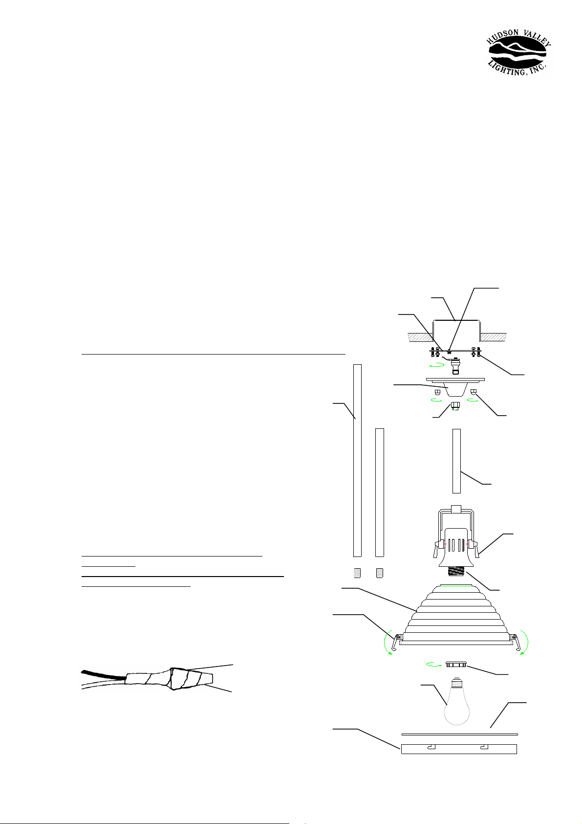
electrical tape
approved fastener
(wire nut)
Stem sections
Metal shade
Latch
Retaining ring
Mounting Plate
Canopy
Outlet box
Swivel
Lamp
Green Screw
End ball
Stem
Lever
Threaded socket
Ring
Screw
Glass diffuser
Page 2
8. Remove the ring from the threaded socket. Place the metal shade over the socket and reinstall the ring.
9. Place the glass diffuser into the retaining ring.
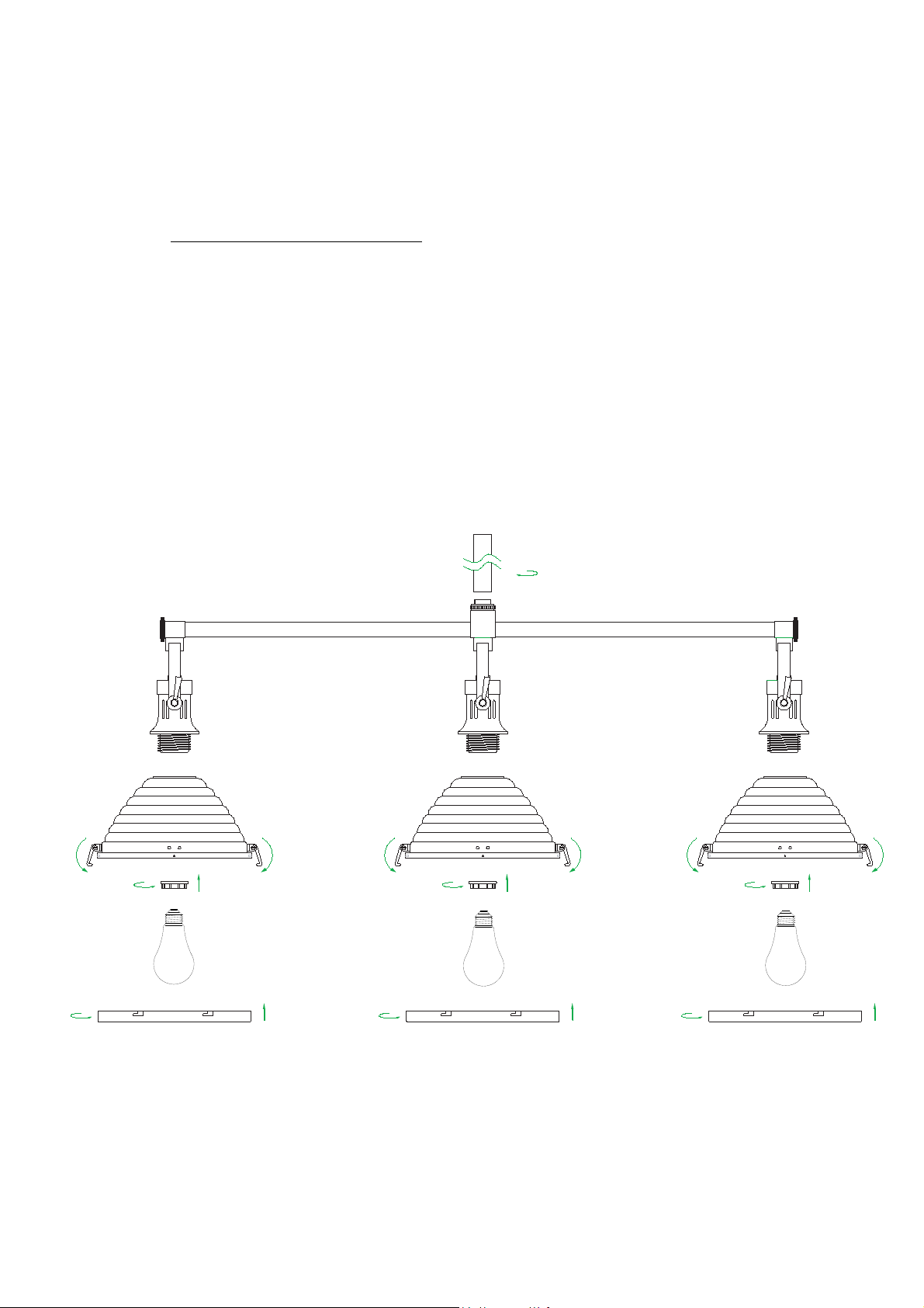
Bend the tabs down to hold it in position(to install 5123 the three lites island, please refer to fig. 2 for detail).
10. Install the lamp ( light bulb).
NOTE: The 5109 & 5111 are rated for a 100 watt type A lamp.
5115 is rated for a 150 watt type A lamp. The 5123 is rated for 3-100 watt type A lamp.
DO NOT EXCEED RECOMMENDED WATTAGE
11. Loosen the 3 latches.
12. Align the locking studs in the shade with the bayonet slots in the ring.
Lift the ring and turn it so that the studs seat in the slots.
13. Lower the latches into position to additionally hold the diffuser and ring in place.
14. Restore power to circuit at breaker or fuse box.
!
Fig. 2
 Loading...