

Hudson WA400, WA4220, WA456 Repair Manual
- 1/39 -
HA Repair Guide
Top-Load Washer
Hudson-PJT
WA400/422/456
- 2/39 -
• Vibration
• Noise
Vibration
& Noise
• Water Leakage
Leakage
• Water Supply
• No Power
Improper
Operation
• Error mode
• Test mode / Diagnosis
Power &
Error
• Circuit Diagram / PBA
Appendix
Hudson-PJT Repair Guide
[ WA400/422/456]
- 3/39 -
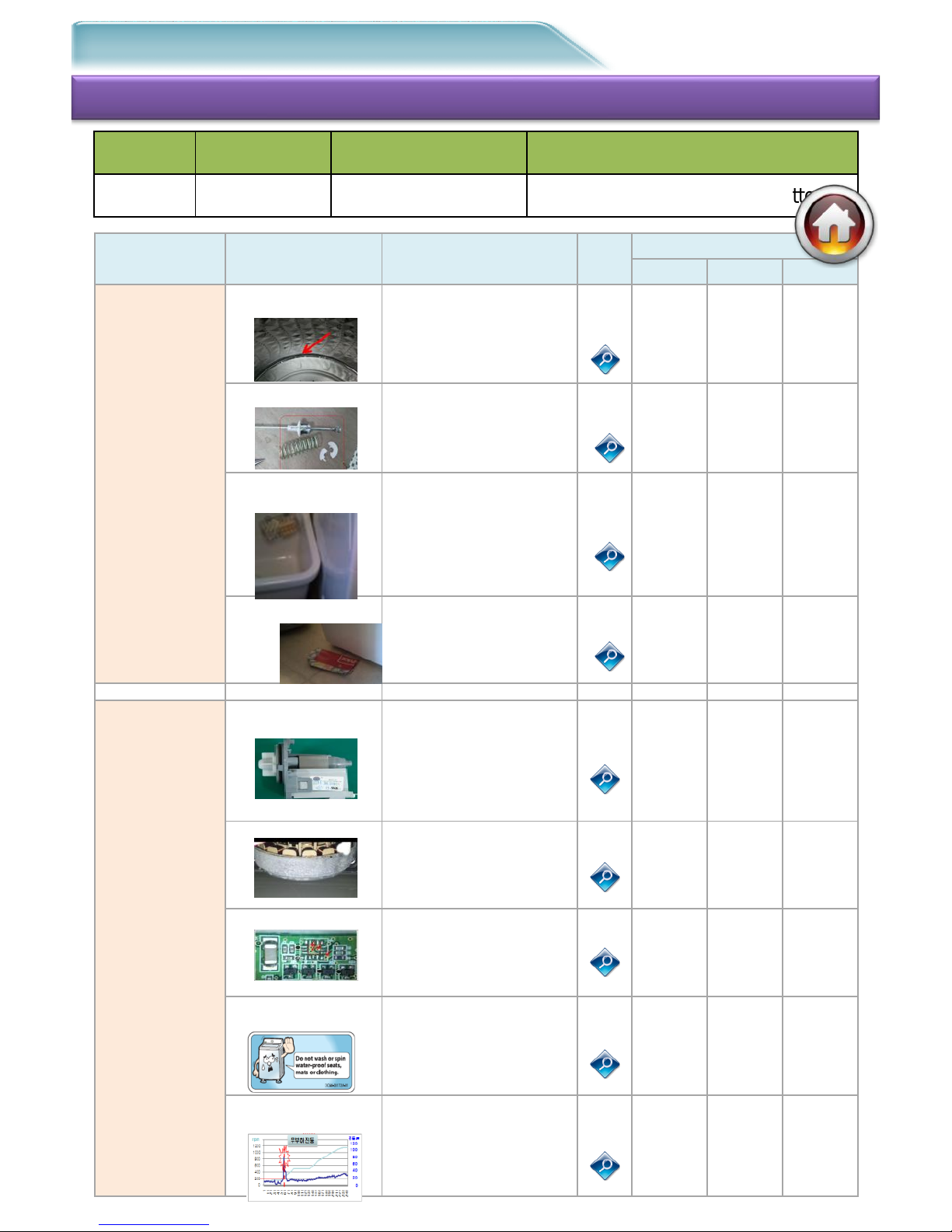
#1. Symptom : Vibration & Noise
1-1. Schematic Diagram of Repair
Check-1
Cause
Check-2
Tip
Code
Block
# 1
# 2
# 3
Spin-Vibration
1.Spin-basket defect
Spin friction abrasion
Concentricity Check (4mm↓)
Curing part burst
Spin-Nut loosening check
1-1
Spin-
Basket
Spin-Nut
+Clutch
Moisture-
proof
cloth
2.Damper defect
Tub moving inclination
check
Grease/Parts check
Low-temp installation
environment
1-2
Damper
Moisture-
proof
cloth
Low-
Temp
Environm
ent
3. Unstable installation
place
Floor moisture environment
Low-temp environment
installation
Dryer Pair installation
narrow
Rear hose interference
Floor shaking
1-3
Installatio
n place
Install
Environm
ent
4.Unstable installation of
product
Leg level installation check
Non-Slip Pad not attached
Moving Pad/Pan-Drain
1-3
Level
installatio
n
Non-Slip
Sheet
Install
Product Noise
1.Pump-Drain defect
Pump-Case damage
Fixing bolt loosening
Foreign substance in Pump
Impeller damage
1-4
Pump-
Case
Impeller
Foreign
Substanc
e
2.Clutch,Motor defect
Spin-mode PBA Check
Abnormal noise diagnosis
Motor friction Check
1-5
Main-PBA
(IPM)
Hall-S/S
Motor
3.MEMS Sensor defect
Error Mode Check -8E1
Voltage Check
Loose Terminal Check
4-11
Main-PBA
MEMS
Harness
4.Customer misunderstan
ding NDF
Customer use moistureproof cloth
Washing a little amount
Spin-only course used
Not using the Net only for
bedding
1-6
Moisture-
proof
cloth
Washing
of Little
Amount
Not using
for-
special-
use net
5. Product inherent
feature
Resonance RPM frequency
shaking
Shaking at the beginning
Sound of Tub water
(Add salt water to Balancer)
1-6
Resonance
Phenomen
on
Balancer
Chassis
Project
Basic Model
Type
Top-Load
Hudson
WA400/422/456
Tub With Pump / Tact Button
- 4/39 -
Step 1
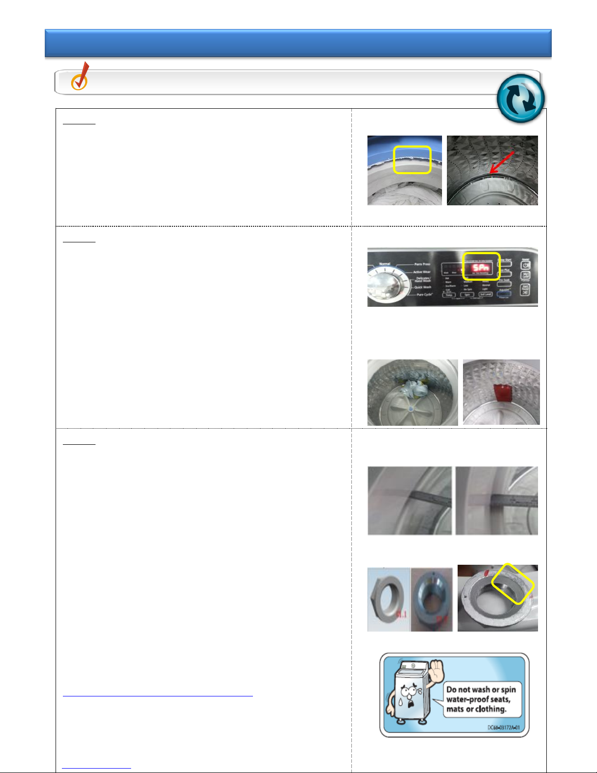
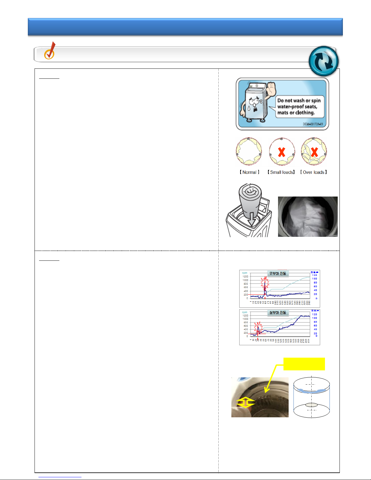
① Spin-Basket Exterior Damage Check
- Check the friction phenomenon at the top.
- Check the opening of Wrapper bottom.
※ If exterior damage or friction phenomenon occurs
as in the photo, replace the Spin-Basket & TubCover.
Step 2
① Spin Mode Check
- Turn knob and select SPN to start.
- Check if the max RPM is reached. (800rpm ±10%)
② Unbalance Test Check
- Run Spin Test with Unbalance 400g placed on one
side.
※ 400g – about 3 towels OR Jig for this purpose
only
- Check for abnormal noise & Set moving.
③ If noise or operation does not seem normal, check
Step #3.
Step 3
① Spin-Basket Concentricity Check
- Turn the Spin-Basket based on 9 o’ clock direction
and measure the deviation.
- If it shakes more than 5mm, it is defect.
② Spin–Nut Loosening Check
- When Shaken, the Spin-Basket shakes.
- If the spot of Spin-Nut fastening is inclined to one
side, it is defect.
=> Spin-Basket concentricity defect & Spin-Nut
connection defect
- Replace the Spin-Basket & Spin-Nut.
- Check the customer usage condition and explain to
the customer how to.
※ Explain to the customer after SVC.
① Check the customer usage condition.
- Check if moisture-proof cloth is used and explain
not to use it.
: Water–Proof Sheet, Mats, clothing
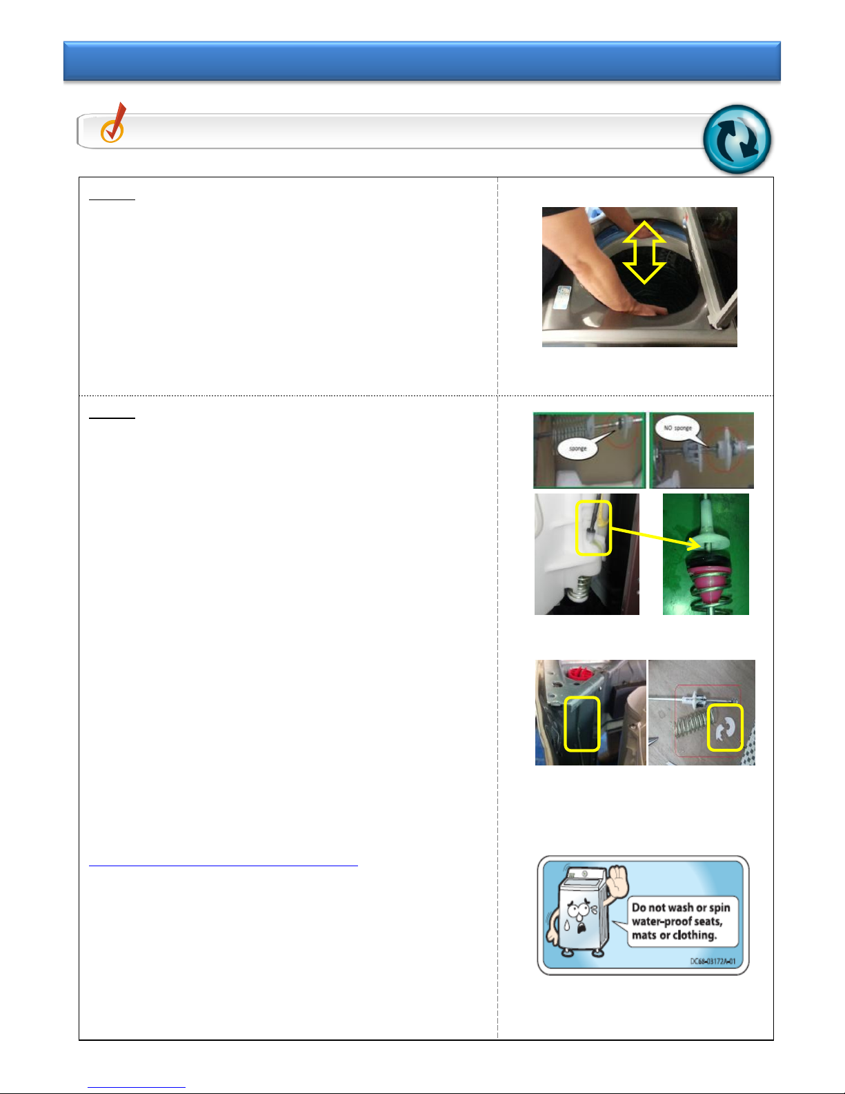
Check Point
Check the condition of Spin-Basket / usage environment.
Tip 1-1. Spin-Basket Abnormality
※ Press and hold Spin+Soil
and push the power button
=> Test Mode
- 5/39 -
Step 1
① Check if Tub moves up and down.
- If the surrounding temperature is below zero at the
time of installation, explain to the customer that it
is inappropriate for the product installation.
② Check if there is noise.
- If Damper does not return or press when checking
abnormal noise & up-and-down movement, check
Step #2.
Step 2
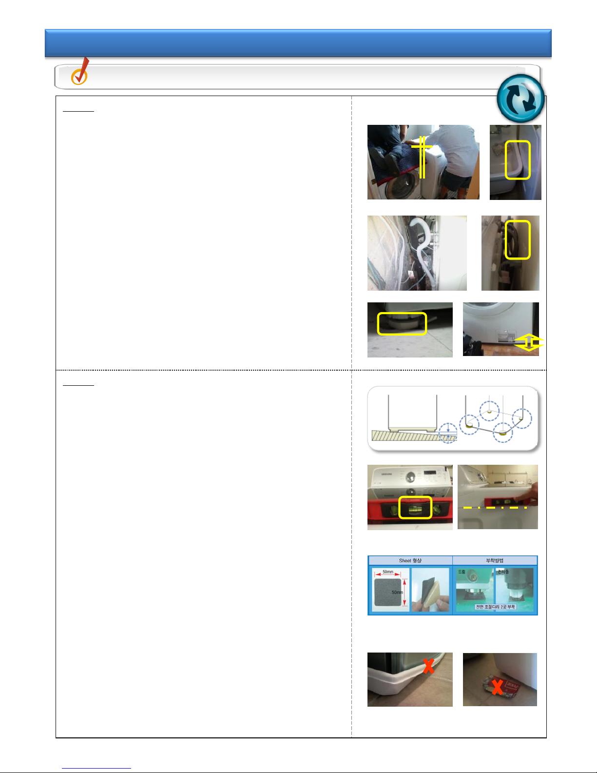
① Check damper parts & the condition of grease
application.
- Check for the loosening of Damper inside.
: Sponge inside is damaged or omitted.
- Check the grease on Damper. Maintain Damper
smooth. Replace the Damper.
② Check if Damper is damaged.
- Replace the Damper.
- Check the usage condition of customer and provide
guidance.
※ Explain to the customer after SVC.
① Check the customer usage condition.
- Check if moisture-proof cloth is used and explain
not to use it.
: Water–Proof Sheet, Mats, clothing
Check Point
Check the condition of Damper operation.
Tip 1-2. Damper Abnormality
- 6/39 -
Step 1
① Check the frictional relationship with the
surroundings when installing.
- Install a pair of dryers attached. If frame is shaking
during spinning mode, interference noise is
generated.
② Friction occurs due to unstable shaping of water
supply/drain hose
- Prevent friction between water supply/drain hose and
product or wall.
③ Floor is shaking, which makes the product move.
Case#1 – Levelness defect due to floor damage.
Case#2 – Shaking due to old laundry room
floor(lumber).
=> It is recommended to contact the installer and request
for re-installation such that it does not influence on
the vibration.
Step 2
① Check the condition of levelness of product
installation.
- For the left and right of product, check the level at
the top of Lid-T/C.
- For the front and rear of product, check the level on
the side of product.
※ When checking the left-and-right level of the product,
Tub is inclined to one side due to tension of Drainhose. (During water supply, it is in the right place.)
※ For level installation, adjust Leg to be attached to the
floor.
② Noise from Set on slippery floor (Tile, Moisture)
- Attach Non-Slip Pad to both front legs on the floor.
- Install the front legs of product to be located on the
Non-Slip Pad.
③ Inappropriate material of leg for the floor
Case#1 Pan Drain Friction Noise
Case#2 Use paper for floor protection on the Leg
bottom.
=> It is recommended to contact the installer and request
for re-installation such that it does not influence on
the vibration.
Check Point
Check the installation place & the condition of unstable installation.
Tip 1-3. Install Place & Unstable Install Abnormality
- 7/39 -
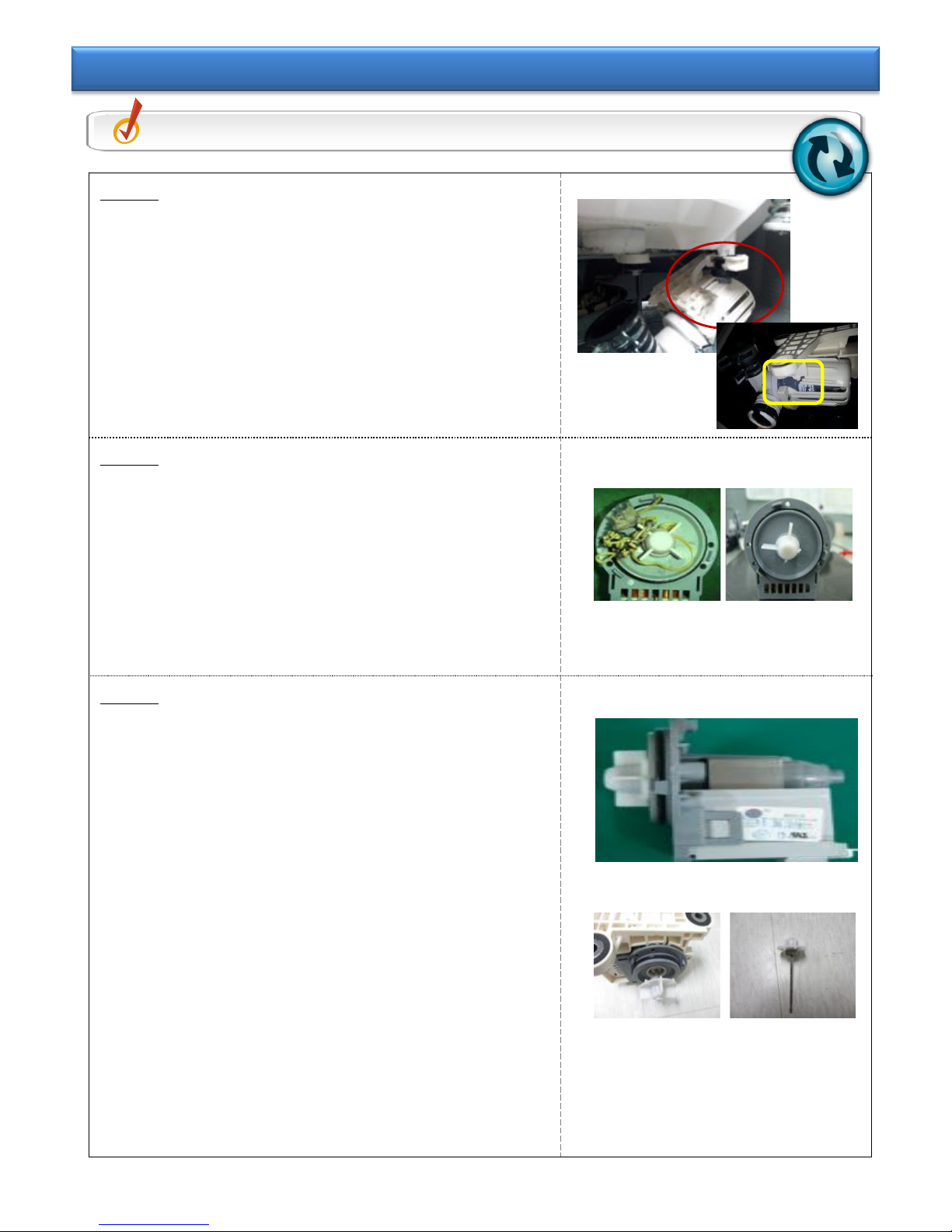
Step 1
① Mechanical Friction Noise
- When pump drain is operating,
it vibrates a little. If drain parts such as
drain hose are near other parts, it may
cause mechanical friction noise.
Step 2
① Foreign materials in Pump Drain
- Open debris filter and check there are
foreign materials such as coins, pins etc.
- Check pump drain impeller is broken.
② If there is noise or operation is not smooth,
check Step #3.
Step 3
① Pump Drain
- If pump drain is defective,
it may cause noise during drain cycle.
In this case, replace pump drain.
② Small foreign materials
- When water is draining through drain hose,
small foreign materials could drain with
water because there is no filter.
So, it can make a little bit of noise but it is
not a problem
=> Replace the Pump-Drain.
Check Point
Check the condition of Pump-Drain.
Tip 1-4. Pump-Drain Abnormality
- 8/39 -
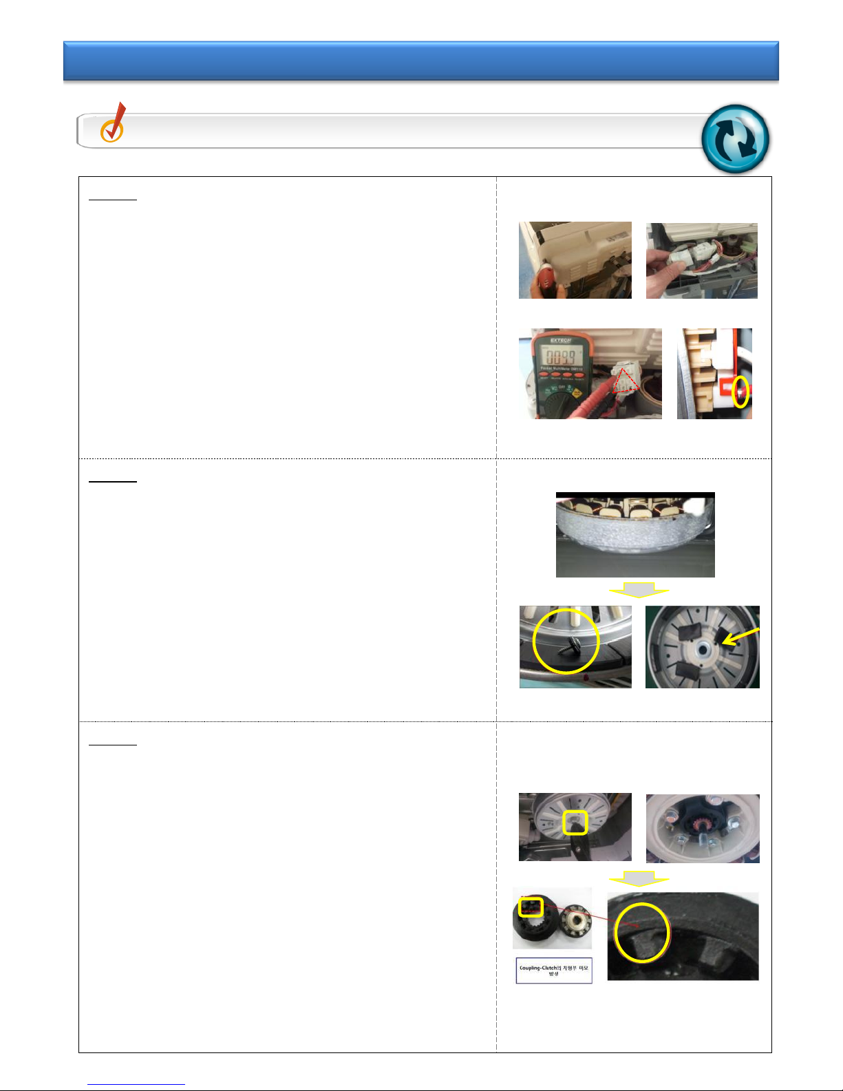
Step 1
① Check for the breakage of wire of washing
motor.
- Separate the Cover-Panel from product.
- Separate the 9Pin housing to measure the
Female terminal.
- Motor Coil Measurement
※ 3 phases of Coil R<->S<->T : 9.8±2Ω
※ Resistance changes due to influence by
Magnetic of Rotor.
② If coil value open defect, check the terminal pin
and replace the stator.
Step 2
① Check the operation of washing motor.
- Turn the power on and start the normal course.
- When weight-sensing is operating, check the
frictional noise of washing motor while Motor-L /
Motor-R is rotating.
② When there is abnormal noise or Rotor
constraint, replace the Rotor.
Step 3
① Check for Clutch noise during spinning mode.
- Press and hold Spin+Soil, while pushing the
power button. =>Test Mode
- Adjust knob and select SPN to start.
- Check if max RPM is reached. (800rpm ±10%)
② If noise is generated from Clutch, disassemble
the Rotor and check for abrasion.
- Disassemble the Rotor.
- Check for the abrasion of Gear of Clutch-Boss
assembly.
=> Replace deformed Clutch Lever and damaged Gear.
Check Point
Check the condition of Clutch & Motor operation.
Tip 1-5. Clutch & Motor Abnormality
① ②
③
① ②
③
④
- 9/39 -
Step 1
① Explain to the customer.
- Check the customer usage condition.
- Check if he/she uses moisture-proof cloth and tell
them not to use it.
: Water–Proof Sheet, Mats, clothing
② Unbalance vibration due to laundry inclined to one
side.
Case#1 – Inclination occurs due to washing small
amount or excessive amount.
Case#2 – Inclination occurs due to using spin-only
course.
Case#3 – When washing bedding, bedding net is not
used.
=> Check the customer usage condition and explain
how to use it correctly.
Step 2
① Resonance phenomenon occurs in the rising
section during spinning mode.
- Hudson Resonant Frequency : 200~450rpm section
- In the resonant frequency, Tub moves.
※ The resonance phenomenon occurs in the rpm
rising section at the beginning for spinning, which
is normal.
② The sound of water is generated when shaking
tub.
- Explain that the sound comes from salt water which
is the center of gravity in the Balancer and that it is
normal.
※ If there is no water sound in the Balancer when
checking the Tub, it is defect. Thus, replace the
Spin-Basket.
=> Explain that it is one of the characteristics created
while designing the product.
Check Point
Explain the NDF and the product characteristics.
Tip 1-6. Explanation of NDF & Product Characteristics
Salt-Water
- 10/39 -
#2. Symptom : Water Leakage
2-1. Schematic Diagram of Repair
Check-1
Cause
Check-2
Tip
Code
Block
# 1
# 2
# 3
Water Supply
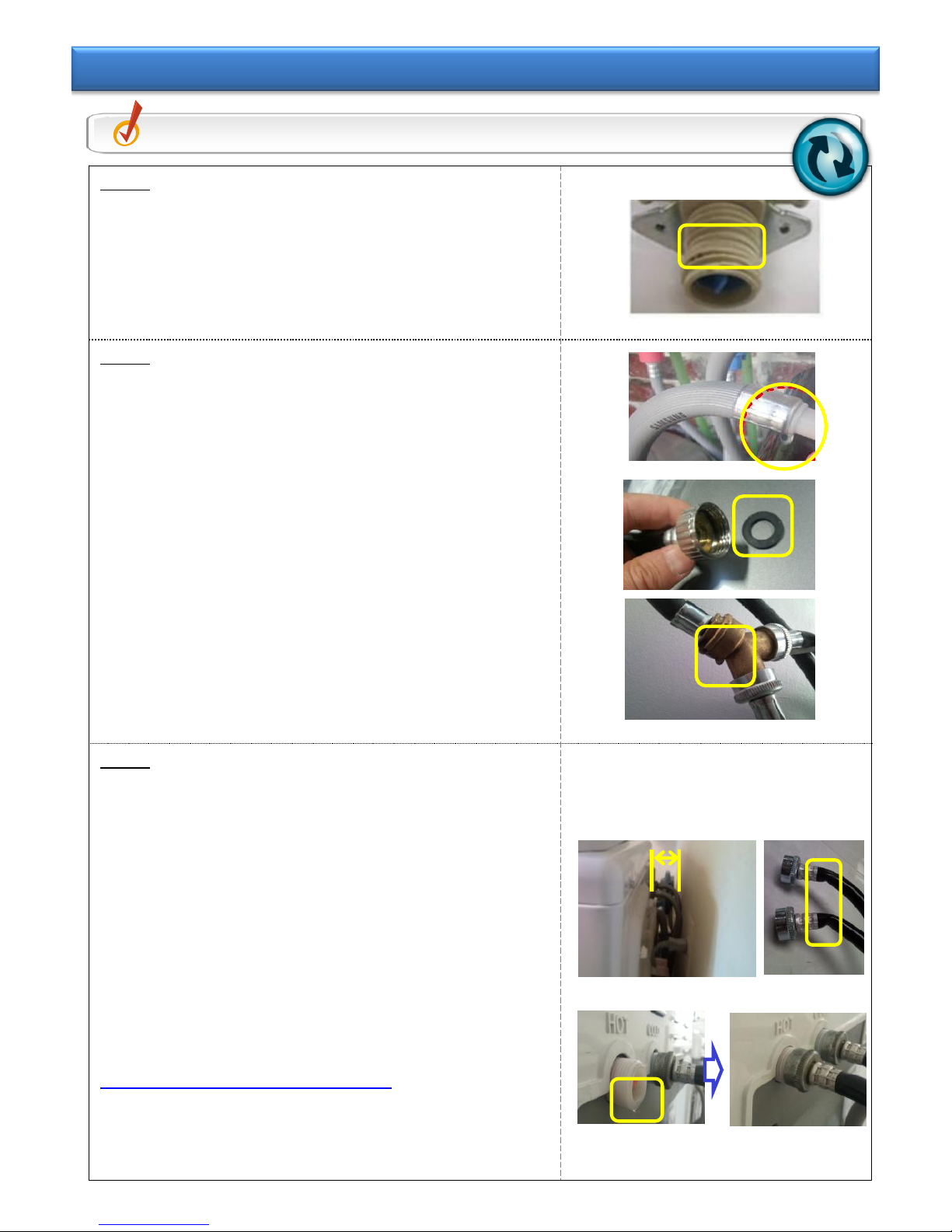
1. Water Supply
Hose Connection
Tool over-connection
loose
Packing omitted
Y-Joint Seal water
leakage
Cold-water-only
installation
Wall-attached
installation
2-1
Water
Supply
Hose
Water
Supply
Valve
Y-Joint
2.Water-V/V
Leakage
Foreign substance
enters pipe
End of water supply
valve damaged
Body damage
Bad packing assembly
Freeze in the winter
2-2
Water
Supply
Valve
Water
Supply
Hose
Piping
3. Detergent
Drawer Leakage
Nozzle spray angle
Bleach overflow
Water pressure /
Inclined installation
Too much laundry
input
2-3
Install
Condition
-slope
-water
pressure
-filter
Nozzle
Washing
Amount
4.Tub-related
leakage
Water level hose
damage
Aquajet overflow
Tub Crack
Damage by coin
2-4
Tub
Coin
5.Pump leakage
Pump-Drain hose
Pump-Case
Drain hose
2-5
Pump-
Case
Drain-
Hose
Installation/
NDF
1. Install & NDF
Waste water
backward-flow
Continuous drainage
Drops a little
2-6
Drain
Hose
Clamp
Pulsator
Chassis
Project
Basic Model
Type
Top-Load
Hudson
WA400/422/456
Tub With Pump / Tact Button
- 11/39 -
Step 1
① Over-connection of water supply hose using a tool
- The screw-head of water supply valve is loose due to
abrasion.
- Leakage occurs in the scratched part of the end of
water supply valve.
Step 2
① Water Supply Hose Unit Check
- Water leaks due to loose caulking.
- Check the water pressure: Shall not exceed max of
8kgf.㎠.
② Check for defect in installed sub-material unit.
- Check if internal Packing-Seal is omitted or worn out.
- Check for water leakage of Y-Joint Unit.
: Apply more Seal Taping to the water-supply-related
parts.
③ If water leaks due to installation condition outside the
product, check Step#3.
Step 3
① Hose is bent during installation.
- Water leaks due to hose bending and friction caused
by the installation of product rear close to the wall.
- It is recommended that the gap between the product
rear and the wall be maintained at 6in(152㎜).
② Water leaks due to backward-flow when installing
cold-water-only.
- Water leakage due to backward-flow phenomenon of
internal Drawer.
- Error occurs during hot water course; and thus explain
to the customer to install both hot and cold water.
※ Explain to the customer after SVC.
=> It is recommended that the installer re-install it such
that it does not influence on water leakage and
vibration.
Check Point
Check the condition of Water-Hose.
Tip 2-1. Water-Hose & Connection Abnormality
- 12/39 -
Step 1
① Check if the Filter of water supply hose is
clogged by foreign substance.
- Separate the Filter with a tool.
② Check for the clogging and clean the Filter.
- Clean it regularly to prevent accumulation of
foreign substance.
- Prevent the water leakage caused by valve.
Step 2
① Check the exterior of water supply valve unit.
- Check if the screw-head is worn out due to overconnection of water supply hose using a tool.
- Check for the scratch at the end of water supply
valve in the process of installation.
② Check for the water leakage part of water supply
valve.
- Water leaks due to continuous water supply
because foreign substance enters inside.
- Water leaks due to damaged body of water
supply valve.
- Water leaks due to bad Packing connection.
③ If noise or operation is not normal, check Step #3.
Step 3
① Water Suply Valve Body Damage
- The body of water supply valve is damaged due
to cold temperatures.
※ Explain to the customer after SVC.
Explain to the customer to re-install the product
such that it is not influenced by cold
temperatures
Check Point
Check the Water-V/V & Connection.
Tip 2-2. Water-V/V & Connection Abnormality
 Loading...