

Hudson Terraplane 1950, Pacemaker 500, Super Six 501, Commodore Six 502, Super Eight 503 Owner's Manual
...Page 1
Page 2

Page 3

Welcome
Your selection of a new Hudson Motor car is gratifying to us and we are happy to welcome you to the
ever growing family of Hudson owners.
We share in your pride of ownership and are sure
you will derive the many miles of enjoyable service
to which you looked forward when purchasing it.
Your new Hudson has been carefully engineered
and built and naturally, you will want to keep it
trouble free and protect the investment in your purchase to the utmost.
With this thought in mind, we have prepared this
Owner's Manual which contains comprehensive
information to assist in giving this fine piece of
mechanism the care and attention it deserves. In its
pages you will find many suggestions to acquaint
you with its construction, operating features and
maintenance requirements.
Take a few minutes to study this manual at your
early convenience. It contains a wealth of
information—just the things you will want to know.
Then place it in the locker box where it will be
available for future reference.
HUDSON MOTOR CAR COMPANY
Service Department
Page 4

WARRANTY
.
"We warrant each new car manufactured by us to be free
from defects in material and workmanship under normal use
and service, our obligation under this warranty being limited
to making good at our factory any part or parts thereof,
including all equipment or trade accessories ( except tires)
supplied by the Car Manufacturer, which shall, within
ninety (90) days after making delivery of such vehicle to
the original purchaser, or before such vehicle has been
driven 4,000 miles, whichever event shall first occur, be
returned to us with transportation charges prepaid, and
which our examination shall disclose to our satisfaction to
have been thus defective ; this warranty being expressly in
lieu of all other warranties expressed or implied, and of all
other obligations or liabilities on our part, and we neither
assume nor authorize any other person to assume for us
any other liability in connection with the sale of our
vehicles.
"This warranty shall not apply to any vehicle which shall
have been repaired or altered by other than an Authorized
Hudson Dealer in any way so as, in the judgment of the
Manufacturer, to affect its stability or reliability, nor
which has been subject to misuse, negligence or accident."
HUDSON MOTOR CAR COMPANY
Detroit, Michigan, U.S, A.
The Hudson Motor Car Company reserves the right to
make any changes in or improvements on its products without incurring any liability or obligation whatever, and
without being required to make any corresponding changes
or improvements on products theretofore manufactured or
sold
Page 5
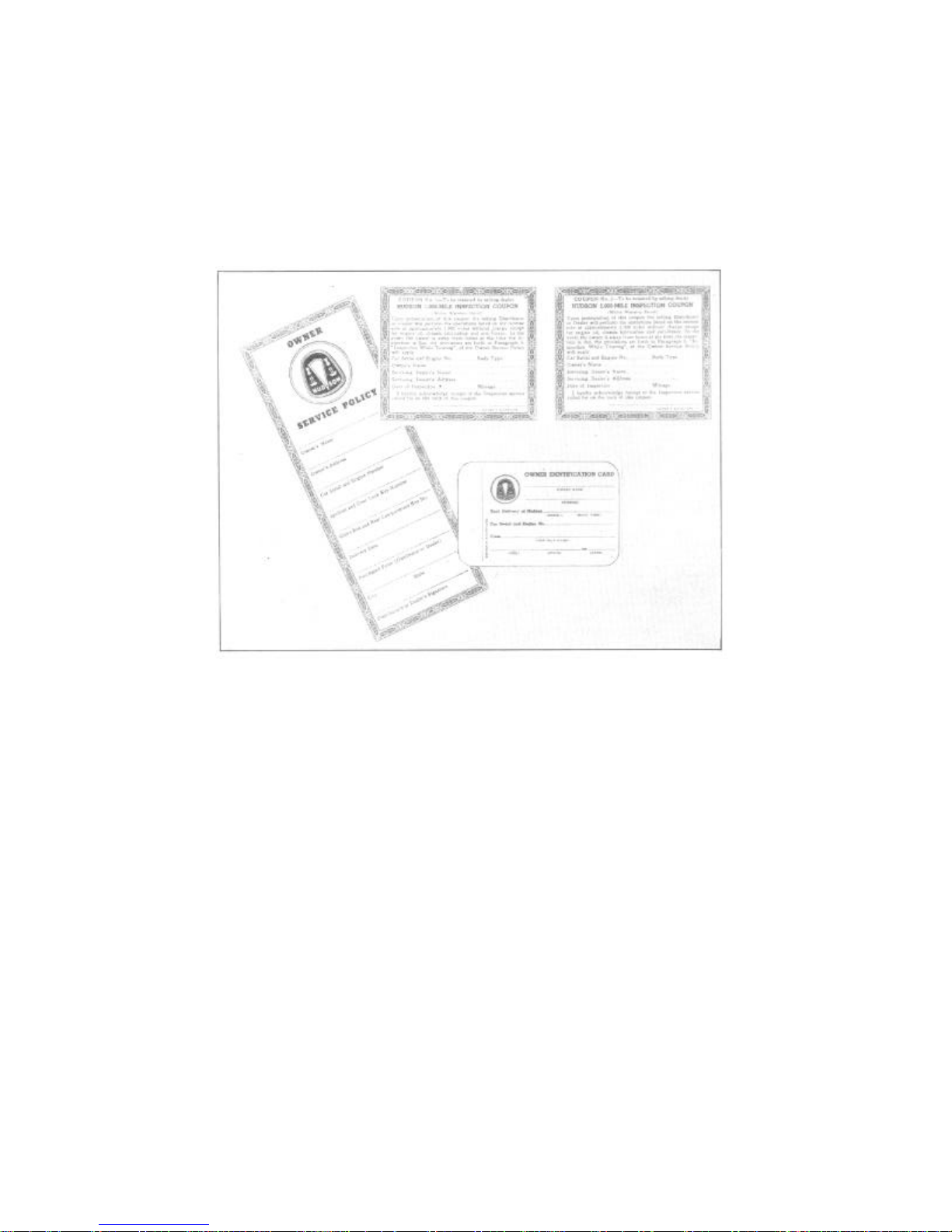
OWNER'S SERVICE POLICY
When you purchased your new Hudson, the Distributor or Dealer from
whom you bought the car presented you with your Hudson Owner's
Service Policy. We cannot too greatly impress you with the need for
reading it fully and becoming acquainted with its provisions.
This policy includes two coupons which entitles you to the 1000 and
2000
Mile Inspections without charge and outlines our obligations as
Manufacturer as well as those of the Car Dealer and the Owner. It also
contains other pertinent information regarding the new car inspections
and fully explains the provisions of the new car warranty concerning
the replacement of parts.
A full knowledge of its contents will preclude the possibility of
misunderstandings should it be necessary to consult your own or some
other Hudson Dealer in regard to the provisions outlined.
Page 6
AUTHORIZED
Your Authorized Hudson Dealer is the logical place to visit for the best available service on your
new Hudson car. It is to his best interests to keep your car in good operating condition at the lowest
possible cost.
In event the need for service arises when touring or away from home, look for the Authorized
Hudson Dealer service sign illustrated above. The Hudson Dealer displaying this sign is your
assurance of the same efficient, friendly service you receive at home. It is your further assurance
that his Service Department handles genuine Hudson parts, uses factory approved methods and
HUDSON SERVICE
STATIONS
tools and employs capable and courteous mechanics.
FIRST THINGS TO DO
When your new Hudson is delivered to you, make sure that:
1. Owner's Service Policy has been properly filled in and its provisions fully explained to you.
2. Identification Card is completely filled in on both sides and key numbers recorded.
3. Radio Warranty Registration Card is filled in and attached to radio.
4. Battery is properly registered with a National Battery Dealer.
Page 7

HUDSON OWNER MANUAL 5
INSPECTION AND ADJUSTMENT SERVICE
Your Hudson Owner's Service Policy entitles you to inspection and adjustment
service, which will be performed by the Hudson Dealer who sold the car, without
charge, except for supplies and lubricants used. These inspections will be made at
the expiration of l,000 miles and again after 2,000 miles of driving.
If these services become due while you are touring or away from home, they may
be performed by any authorized Hudson Dealer, who will make a charge of not
more than $5.00 for either inspection. The dealer who made the inspection will
furnish you with a receipted bill and sign the inspection coupons attached to your
Warranty, which should then be presented to the dealer (who sold the car). on your
return. Your dealer will then credit your account in the above amount for each
inspection performed. We suggest that you carefully read the provisions of the
Owner's Service Policy so that you will fully understand this procedure.
The inspection and adjustment service consists of the following:
1,000 Mile Inspection
1. Hand and Foot Brake Operation.
2. Operation of All Locks.
3. Signals and Instruments.
4. Clutch Pedal Clearance.
5. Change Clutch Oil.
6. Battery and Connections.
7. Check Oil Level, Motor, Transmi sion and Rear Axle.
8. Check Flywheel Timing.
2,000 Mile Inspection
1. Hand and Foot Brake Operation.
2. Signals and Instruments.
3. Operation of All Lights.
4. Operation of Windshield Wipers.
5. Battery and Connections.
6. Check Oil Level, Engine, Transmis
- sion and Rear Axle.
7. Check Generator Charging Rate.
8. Cooling System and Connections
9. Adjust Carburetor Idle.
10. Tighten Cylinder Head Stud Nuts.
11. Cooling System and Coolant.
12. Check Tightness of Rear Wheel
Hubs.
13. Wheel Hub Bolts.
14. Rear Spring Mounting Clips.
15. Road Test.
9. Adjust Tappets—Engine Hot.
10. Clean and Regap Spark Plugs.
11. Clean and Adjust Distributor
Points
.
12. Check Timing at Flywheel.
13. Adjust Carburetor Idle.
14. Check Tightness of Wheel Hub
Bolts.
15. Check Operation of Super-Matic
Drive, Drive-Master and Overdrive.
16. Tighten Manifold Stud Nuts
17. Road Test Car
Page 8

6 HUDSON OWNER MANUAL
MODEL DESIGNATIONS AND SERIAL NUMBERS
The new Hudson models are produced in the Pacemaker, Super and Com-
modore Series and are designated as follows:
Hudson Pacemaker Series...............................................Model 500
Hudson Super Six Series ................................................Model 501
Hudson Commodore Six Series ......................................Model 502
Hudson Super Eight Series.................................................Model 503
Hudson Commodore Eight Series.....................................Model 504
LICENSE INFORMATION
HUDSON PACEMAKER SERIES— MODEL 501
A.M.A..
H.P. Rating Weight
Pounds
30.4
30.4
30.4
30.4
30.4
30.4
30.4
30.4
30.4
30.4
30.4
30.4
28.8
28.8
28.8
Body Types
Brougham
4 Door Sedan
Business Coupe
Club Coupe
Conv. Brougham.
Brougham
4 Door Sedan
Club Coupe
Conv. Brougham
4 Door Sedan
Club Coupe
Conv. Brougham
Brougham
4 Door Sedan
Club Coupe
Wheel-
base
119"
119"
119"
119"
119"
HUDSON SUPER SIX MODEL—SERIES 501
124"
124"
124"
124"
HUDSON COMMODORE SIX MODEL—SERIES 502
124"
124"
124"
HUDSON SUPER EIGHT MODEL—SERIES 503
124"
124"
124"
HUDSON COMMODORE EIGHT MODEL—SERIES 504
Starting
Serial No.
500101
and up
501101
and up
502101
and up
503101
and up
No. of
Cyls. Bore Stroke
6
3-9/16"
6
3-9/16"
6
3-9/16"
6
3-9/16"
6
3-9/16"
6
3-9/16"
6
3-9/16"
6
3-9/16"
6
3-9/16"
6
3-9/16"
6
3-9/16"
6
3-9/16"
8
8
8
3"
3"
3"
3-7/8"
3-7/8"
3-7/8"
3-7/8"
3-7/8"
4-3/8"
3-9/16"
3-9/16"
3-9/16"
3-9/16"
3-9/16"
3-9/16"
4-1/2"
4-1/2"
4-1/2"
4 Door Sedan
Club Coupe
Conv. Brougham
124"
124"
124"
504101
and up
8
8
8
3"
3"
3"
4-1/2"
4-1/2"
4-1/2"
28.8
28.8
28.8
The car serial number which is also the engine number, is stamped on a metal plate attached to the
right front door hinge pillar post. In the car numbering system, the first three digits of the serial number
indicate the series and model, while the remaining digits represent the actual car number. As the cars
leave the production line, they are numbered in consecutive order, regardless of series or model. As
an example, the car built after 500999 would be numbered 5011000, 5021000, 5031000 or 5041000
instead of 502000.
The engine number is stamped on the top of the cylinder between Nos. 1 and 2 exhaust manifold
flanges on eight cylinder engines and on the right side of the cylinder at the upper front end, stamped
vertically, on six cylinder engines.
NOTE: Do not confuse engine number with casting or other numbers appearing at different
locations on the engine. Be sure this number corresponds with the one shown on your Owner Policy
and Identification Card.
A code letter or letters indicating the car paint color option is stamped on the upper hinge of the right
front door.
Page 9

HUDSON OWNER MANUAL 7
TECHNICAL INFORMATION
ENGINE
Series and Model
Arrangement
Bore and Stroke
Piston Displacement
Horsepower—Taxable
Actual
Compression Ratio—Std
Optional
Engine Mounting
Camshaft Drive
Camshaft Bearings
Crankshaft—Type
Canshaft Bearings
Connecting Rods Length—Center to
Center
Lower End Bearing
Material
Upper End Bearing—
Diameter and Length
Pistons—Type
Material
Clearance
Piston Pin—
Type and Length
Diameter
Piston Rings—Material
Compression Rings
Oil Rings
Gap Clearance—All
Rings
Valves—
Intake—
Head Outside Diameter
Lift
Operating Clearance—Hot
Exhaust—
Head Outside Diameter
Lift
Operating Clearance—Hot
Lubricating Method
Pump Type
Oil Capacity—Qts.
Oil Capacity—Qts.
Pacemaker Six
—Model 500
L Head
3-9/16" x 3-7/8"
232 Cu. In.
30.4
112 at 4200
R.P.M.
6-7:l
7.2 : 1
3-Rubber
Morse Chain
4-Steel—Babbitt
Compensated
4-Steel—Babbitt
8-1/8"
Replaceable
Steel—Babbitt
Steel—Babbitt
3-1/32" x l-l/8"
Cam Ground
Aluminum Alloy
.0015" to .002" .
Floating 2-15/16"
31/32"
4—Cast Iron,
Pinned
2
2—l below pin
.007" to .012"
1-53/64"
11/32"
.008"
1-9/16"
11/32"
.010"
Pressure
Rotor
7-1/2—Dry
7—Refill
CLUTCH
Super Six and
Commodore Six
—Models 501, 502
L Head
3-9/16" x 4-3/8"
262 Cu. In.
30.4
123 at 4000
R.P.M.
6-7:l
7.2:1
3-Rubber
Morse Chain
4-Steel—Babbitt
Compensated
4-Steel—Babbitt
8-1/8"
Replaceable
Steel—Babbitt
Steel—Babbitt
3-1/32" x l-l/8"
Cam Ground
Aluminum Alloy
.0015" to .002" .
Floating 2-15/16"
31/32"
4—Cast Iron,
Pinned
2
2—l below pin
.007" to .012"
1-53/64"
11/32"
.008"
1-9/16"
11/32"
.010"
Pressure
Rotor
7-1/2—Dry
7—Refill
Super Eight and
Commodore Eight
—Models 503, 504
L Head
3" x 4-1/2"
254 Cu. In.
28.8
128 at 4200
R.P.M.
6-7:l
7.2:1
3-Rubber
Morse Chain
5-Steel—Babbitt
Compensated
5-Bronze—Babbitt
8-3/16"
Integral
Steel—Babbitt
Bronze
3/4" x 29/32"
Cam Ground
Aluminum Alloy
.0015" to .002" .
Floating 2-7/16"
3/4"
4—Cast Iron,
Pinned
2
2—l below pin
.004" to .009"
1-1/2"
11/32"
.006"
1-3/8"
11/32"
.008"
Duo-Flow
Oscillating
Plunger
8—Dry
7—Refill
Type—Oil Cushioned
Pilot Bearing
Throw-out Bearing
Pedal Lash
Clutch Lubricant
9"—Single Plate
10" with Super Matic Drive or
Drive-Master
Ball
Ball
l-l/2"
1/3 Pint Hudsonite
10"—Single Plate
Ball
Ball
l-l/2"
1/3 Pint Hudsonite
10"—Single Plate
Ball
Ball
l-l/2"
1/3 Pint Hudsonite
Page 10

8 HUDSON OWNER MANUAL
TRANSMISSION
Series and Model
Pacemaker Six
—Model 500
Super Six and
Commodore Six
—Models 501, 502
Super Eight and
Commodore Eight
—Models 503, 504
Type
Speeds
Gear Type
Gear Ratio—Low
Second
High
Reverse
Lubrication—Summer
Winter
Capacity—Without
Overdrive
With Super-Matic Drive
or Overdrive
No. of Universals—
Front Shaft
Rear Shaft
Center Bearing
Bearing Lubrication
Spline Lubrication
Universal Lubrication
Type
Gear and Pinion
Ratios
Pinion Bearings
Adjustment
Differential Bearings
Adjustment
Rear Wheel Bearings
Adjustment
Gear and Pinion Back Lash
Lubricant
Capacity
Type
Camber
Caster
Toe-In
Pivot Pin Inclination
Wheel Bearings
Synchro-Mesh
3 Fwd., 1 Rev.
All Helical
2.88: 1
l.82:1
1:l
3.5 : 1
90 E.P. Mild
80 E.P. Mild
2 Pints
3-l/4 Pints
PROPELLER SHAFT
1
2
Annular Ball
Prelubricated
Pressure Fitting
Pressure Fitting
REAR AXLE
Semi-Floating
Hypoid
4.l, 4.55, 3.82
Taper Roller
Shim
Taper Roller
Adjusting Nuts
Taper Roller
Shim
.004" to .006"
S.A.E. 90 Multi Purpose Gear
Lube
3-l/2 Pints
FRONT SUSPENSION
Coil Spring
1/2 to l-l/2 deg.
1/2 to l-1/2 deg.
0 to 1/16"
3 deg. 36 min. A
Taper Roller
REAR SPRINGS
Synchro-Mesh
3 Fwd., 1 Rev.
All Helical
2.88: 1
l.82:1
1:l
3.5 : 1
90 E.P. Mild
80 E.P. Mild
2 Pints
3-l/4 Pints
1
2
Annular Ball
Prelubricated
Pressure Fitting
Pressure Fitting
Semi-Floating
Hypoid
4.l, 4.55, 3.82
Taper Roller
Shim
Taper Roller
Adjusting Nuts
Taper Roller
Shim
.004" to .006"
S.A.E. 90 Multi Purpose Gear
Lube
3-l/2 Pints
Coil Spring
1/2 to l-l/2 deg.
1/2 to l-1/2 deg.
0 to 1/16"
3 deg. 36 min. A
Taper Roller
Type
Length and Width
Shackle Type
Lubricant
Leaf—Semi Elliptic
54" x l-3/4"
Threaded "U"
Viscous Lubricant
Leaf—Semi Elliptic
54" x l-3/4"
Threaded "U"
Viscous Lubricant
Leaf—Semi Elliptic
54" x l-3/4"
Threaded "U"
Viscous Lubricant
Page 11

HUDSON OWNER MANUAL 9
STEERING GEAR
Series and Model
Pacemaker Six
—Model 500
Super Six and
Commodore Six
—Models 501, 502
Super Eight and
Commodore Eight
—Models 503, 504
Type
Ratio
Steering Wheel Diameter
Lubricant
Type
Drum Diameter
Lining Type
Width
Clearance—Shoes
Free Pedal Travel
Type
Size—Standard
Optional
Wheel Size—Standard .
Optional
Inflation Pressures
Capacity in Quarts
Pump Type
Temperature Control
Pump and Fan Drive
Fan
Belt Adjustment
Pump Bearings
Worm and Roller
18.2 to 1
18"
90 E.P. Gear Lube
BRAKES
Duo-Automatic
1"
Moulded
Front, l-3/4"
Rear, 1-3/4"
.010"
1/4"
TIRES
Super Cushion
7.10 x 15, 4 Ply
7.60 x 15, 4 Ply
5.00 x 15
5.50 x 1
Front—26 Lbs.
Cold
Rear—24 Lbs.
Cold
COOLING SYSTEM
19—With Heater.
20
6 Vane Impeller
Thermostat—By Pass
Vee Belt
4 Blade
At Generator
Prelubricated
Worm and Roller
18.2 to 1
18"
90 E.P. Gear Lube
Duo-Automatic
1"
Moulded
Front, 2-1/4"
Rear, 1-3/4"
.010"
1/4"
Super Cushion
7.10 x 15, 4 Ply
7.60 x 15, 4 Ply
5.00 x 15
5.50 x 1
Front—26 Lbs.
Cold
Rear—24 Lbs.
Cold
17—With Heater.
18
6 Vane Impeller
Thermostat—By Pass
Vee Belt
4 Blade
At Generator
Prelubricated
Carburetor
Type and Size
Choke
Heat Control
Fuel Delivery
Air Cleaner—Std.
Optional
Fuel Tank Capacity
Make
Distributor Rotation
Drive
Advance
Contact Point Gap
Timing
Firing Order
FUEL SYSTEM
Carter, WAI-749S
Single, l-l/4"
Automatic
Thermostatic
Pressure Pump
Oil Wetted Type
Oil Bath Type
20 U.S. Gals.
Carter, WDO 647SA
Single, l-l/4"
Automatic
Thermostatic
Pressure Pump
Oil Wetted Type
Oil Bath Type
20 U.S. Gals.
ELECTRICAL EQUIPMENT
Auto-Lite
Clockwise
Camshaft
Vac. & Automatic
.020"
T.D.C.
1-5-3-6-2-4
Auto-Lite
Clockwise
Camshaft
Vac. & Automatic
.020"
T.D.C.
1-5-3-6-2-4
Carter, WDO 648SA
Single, l-l/4"
Automatic
Thermostatic
Pressure Pump
Oil Wetted Type
Oil Bath Type
20 U.S. Gals.
Auto-Lite
Clockwise
Camshaft
Vac. & Automatic
.017"
T.D.C.
1-6-2-5-8-3-7-4
Page 12

10 HUDSON OWNER MANUAL
ELECTRICAL EQUIPMENT—Continued
Series and Model
Generator—Type
Drive
Chg. Rate, Hot—Cold
Starting Motor—Drive
Control
Battery—Make
Plates and Capacity
Terminal Grounded
Location
Spark Plugs—Cast Iron
Head
Aluminum Head
Gap
Pacemaker Six
—Model 500
Shunt Wound Vee
Belt
35 Amps. at 8
Volts
Bendix
Solenoid
National-6 Volt
51-100 Amps.
Positive
Left Side, under
Hood
Champion J7-14
M.M.
Champion H10 14 M.M.
.032
Super Six and
Commodore Six
—Models 501, 502
Shunt Wound
Vee Belt
35 Amps. at 8
Volts
Bendix
Solenoid
National-6 Volt
51-100 Amps.
Positive
Left Side, under
Hood
Champion J7-14
M.M.
Champion H10 14 M.M.
Super Eight and
Commodore Eight
—Models 503, 504
Shunt Wound
Vee Belt
35 Amps. at 8
Volts
Bendix
Solenoid
National-6 Volt
51-100 Amps.
Positive
Left Side, under
Hood
Champion J7-14
M.M.
Champion H10 14 M.M.
LAMP BULBS
No.
C.P. Base
Headlight (Sealed Beam Type)
Bonnet Light
Parking Light with Direction
Indicator
Tail and Stop Light
License Light
Dome Light—Front
Rear Quarter Lights (2)
Clock
Speedometer
Instrument Cluster
Direction Indicator
Radio
Headlight Beam Indicator.
Ignition Lock
Courtesy Light
Fog Light—Sealed Beam
Spot Light—Sealed Beam
Parking Light
Generator and Oil Indicator
Cooling System
Gasoline Tank
Engine Oil—Dry
4030
55
1154
1154
63
87
81
55
55
55
55
55
55
55
87
4015A
4535
63
55
CAPACITIES
U.S.-19 Quarts
Imperial-15-¼
Quarts
Metric-17-3/4
Liters
U.S.-20 Gallons
Imperial-16-2/3
Gals.
Metric-75-¾
Liters
U.S.-7-1/2 Qts.
Imperial-6-½
Quarts
Metric-7 Liters
Sealed
2
21-3
21-3
3
15
6
2
2
2
2
2
2
2
15
Sealed
Sealed
3
2
Sealed
Single
Double
Double
Single
Single
Single
Single
Single
Single
Single
Single
Single
Single
Single
Sealed
Sealed
Single
Single
U.S.-19 Quarts
Imperial-15-¼
Quarts
Metric-17-3/4
Liters
U.S.-20 Gallons
Imperial-16-2/3
Gals.
Metric-75-¾
Liters
U.S.-7-1/2 Qts.
Imperial-6-½
Quarts
Metric-7 Liters
U.S.-17 Quarts
Imperial-14
Quarts
Metric-16
Liters
U.S.-20 Gallons
Imperial-16-2/3
Gals.
Metric-75-3/4
Liters
U.S.-8 Qts.
Imperial-6-2/3
Quarts
Metric-7-½
Liters
Page 13

HUDSON OWNER MANUAL 11
parts, place engine and chassis lubrication in the category of highly specialized services.
not be changed until the recommended change period shown in the Lubrication Schedule
CAPACITIES (CONT.)
Engine Oil - Refil
Clutch
Transmission
Transmission and Overdrive
Rear Axle
Overall Length—Including
Bumpers
Overall Width
Overall Height
Road Clearance—Front
Road Clearance—Rear
Turning Radius—Right
Left
U. S. - 7 Quarts
Imperial - 6 Qts.
Metric - 6-½
Liters
U.S. - 1/3 Pint
Imperial - 1/4
Pint
Metric - 160 C.C.
U.S. - 2 Lbs.
Imperial - 2 Lbs.
Metric - .91 Kgs.
U.S. - 3- 1/4
Lbs.
Imperial - 3-1/4 Lbs.
Metric - 1.47 Kgs.
U.S. - 3-1/2 Lbs.
Imperial - 3 Lbs.
Metric - l.6 Kgs.
DIMENSIONS
201-1/2"
77-1/16"
60-3/8"
8"
8"
Right 19.65 Feet
Left 19.65 Feet
U. S. - 7 Quarts
Imperial - 6 Qts.
Metric - 6-½
Liters
U.S. - 1/3 Pint
Imperial - 1/4
Pint
Metric - 160 C.C.
U.S. - 2 Lbs.
Imperial - 2 Lbs.
Metric - .91 Kgs.
U.S. - 3- 1/4
Lbs.
Imperial - 3-1/4 Lbs.
Metric - 1.47 Kgs.
U.S. - 3-1/2 Lbs.
Imperial - 3 Lbs.
Metric - l.6 Kgs.
208"
77-5/8"
60-3/8"
8"
8"
21 Ft. 2 In.
20 Ft. 5 In.
LUBRICATION
Present day high speed driving, fast acceleration and closely fitted precision machined
A definite plan of application is necessary to provide the various working surfaces with
the right amount of the correct lubricant at the proper time. Contrary to general belief, one
lubricant will not suffice for all parts of the chassis. The varying load demands and operating
conditions which the various parts are subjected to, call for different types of lubricants to
minimize friction and reduce wear.
Your Authorized Hudson Dealer has been provided with the correct factory lubrication specifications for your car, as well as the definite plan of application. This is your
assurance that the lubrication requirements of your car will be met with the greatest care.
Be sure to consult him on this most important matter.
For your guidance, a copy of the Lubrication Chart is attached to the front cover of
this manual. Additional information regarding the lubrication requirements of your car are
given in the Lubrication Schedule shown below and elsewhere in this manual, under the
description of the various units.
The lubricants placed in your car at the time of assembly are of the best quality and need
has been reached.
Page 14

12 HUDSON OWNER MANUAL
Points
Points
Points
Points
Points
Points
Check Oil Level
4 or 8
Remove, wash and add new oil
LUBRICATION SCHEDULE
AT 500 MILES
Drain engine oil reservoir and refill with new oil of good quality. See "The Proper Engine Oil to Use", Page 14.
EVERY l,000 MILES
Viscous Chassis Lubricant
Drag Link
Upper Support Arm Eccentric
Bushing
Upper Support Arm Pivot Bushing
Lower Support Arm Pivot Bushing
Lower Support Arm Support
Bushing
Center Steering Arm Pivot Bearing
Engine
Door Hinge
Gasoline Tank Filler Door
Hinge and Spring 3
Water Resistant Lubricant
Windshield Cables at Pulleys
Door Check Arms
Courtesy Light Switch
Door Lock Bolt and Slide
Door Striker
2 or 4
2 or 4
2 or 4
2 or 4
Rear Compartment Door Hinge
E. P. Gear Lubricant—S.A.E. 80 Winter, S.A.E. 90 Summer
Transmission
Overdrive
Check Level
Check Level
2
Tie Rod End
Steering Spindle Pivot Pins
2
Gear Shift Bell Crank Pivot
4
Clutch Pedal Bearing
4
Clutch Throwout Bearing
Universal Joint Spline
2
Universal Joint Needle Rollers
1
Rear Spring Shackle Bushing
Engine Oil
Rear Compartment Door Striker
Rear Compartment Latch Rod
Hood Hinge
Windshield Wiper Pulleys
4
Rear Compartment Door
Clamping Lever
Hood Prop
Hood Upper Lock
Hood Lower Lock
2
Hood Lower Lock and Control Wire
Steering Gear Check Level
4
2
1
1
1
1
3
4
4
2
8
4
2
2
1
1
2
Multi Purpose Gear Lubricant—S.A.E. 90
Rear Axle Check Level
Distilled Water
Check Battery Electrolyte level and gravity.
Water or Anti-Freeze
Check Coolant level and Anti-Freeze strength.
Hudson Hydraullc Brake Fluid
Check Brake Master Cylinder fluid level
EVERY 2,000 Miles
Perform operations included in 1,000 mile lubrication, in addition to the following:
Engine Oil
Engine—Drain Oil Reservoir and
Air Cleaner - Oil Bath
refill. See "Proper Oil to Use," Page 14
Generator
Starting Motor (501, 502, 503 and
504 Series)
Distributor
Air Cleaner—Standard..Wash and re-oil
2 Points
2 Points
4 Points
Oil Filler Pipe Cap (6 Cyl.)
Throttle Operating Linkage
Brake Operating Linkage
Drive-Master Operating Linkage
Wash and re-oil
All Joints
All Joints
All Joints
Page 15

HUDSON OWNER MANUAL 13
Perform operations included in 1,000 mile and 2,000 mile lubrications, in addition to
the following:
Clutch Drain and Refill
E. P. Gear Lubricant—S.A.E. 80 Winter, S.A.E. 90 Summer
Transmission Drain and Refill Overdrive Drain and Refil
Milti Purpose Gear Lubricant—S.A.E. 90
Rear Axle Drain and Refill
Brake Cables Clean and Lubricate Oil Filter Renew Cartridge
Perform operations included in 1,000 mile, 2,000 mile and 5,000 mile lubrications, in
addition to the following:
Rear Spring Covers Inject lubricant with special lubricating clamp
Front Wheel Bearings
Rear Wheel Bearings
Drive-Master Power Cylinder
Gear Shift Power Cylinder
EVERY 5,000 Miles
Hudsoninte Clutch Compound
Viscous Chassis Lubricant
EVERY 10.000 MILES
Viscous Chassis Lubricant
Sodium Soap Base Lubricant
Remove, clean and repack
Remove, clean and repack
Hudson Shock Absorber Oil
Remove plug and inject 1 ounce oil
Disconnect elbow and inject 1 ounce oil
IMPORTANT: When checking the level of the lubricant in the rear axle and transmission,
make sure that the lubricant has stopped foaming. If the car has been run for a considerable length of time, it should be permitted to stand long enough to allow the oil to reach
the true level before checking.
BREAK-IN OIL
Special compounds or so-called "break-in" oils are not necessary in Hudson engines.
In the event it is decided to use them, make sure the supplier guarantees that they contain
no harmful ingredients.
ENGINE OIL CAPACITIES
The total engine oil capacity is 7-1/2 quarts for six cylinder and 8 quarts for eight
cylinder engines. When the oil is drained in the conventional manner, the refilling
quantity is 7 quarts for both six and eight cylinder engines.
When the oil reservoir is removed for cleaning or during service work, two quarts
should be placed in the oil reservoir tray of eight cylinder engines before the reservoir is
installed. The remaining seven quarts should then be placed in the reservoir through the
crankcase filler opening. In six cylinder engines, the entire quantity is poured through the
crankcase oil filler pipe.
CHECKING ENGINE OIL LEVEL
An engine in normal operating condition is expected to use some oil and it is, therefore, not unusual to add oil between change periods. Its rate of usage is governed by the
individual engine and is dependent on operating speeds, temperatures and the viscosity
and quality of the oil used.
Page 16

The level should be checked each time
fuel is added. The oil level gauge is
located on the left side of the engine
and is divided at its lower end to show
the "Oil Level Range" and the "Low
For normal operation, the oil level is
satisfactory when it is within the "Oil
Level Range". For high speed operation,
the level should be maintained at the full
mark, which is the top line on the "Oil
To make an accurate check, it is best to
wait a minute or two after shutting off the
engine to permit the oil to drain back into the reservoir. Approximately three and
one-half quarts of oil are required to bring the level from low to full in both
eter indicates that the oil change period is near at hand, it is more economical to have
The oil which is placed in the engine at the factory is satisfactory for the first 500
Thereafter, at intervals of 2,000 miles, the reservoir should be drained and
refilled with new oil of good quality. If the car is operated constantly in dusty
areas or for short distances at low speeds during cold weather, which permits
foreign matter and sludge to accumulate, it should be changed more frequently.
However, the actual change period is largely dependent on the individual driving
The oil is drained by removing the plug at the rear of the oil reservoir. To insure
complete draining, it is important that the operation be performed while the
It is good practice to remove the oil reservoir at least twice
a
year, preferably in
Caution: The use of flushing oil or compounds is not recommended. However, in
the event they are used, it will be necessary to remove the oil reservoir and thoroughly
The use of high-grade engine oil of the correct type is of great importance in
obtaining maximum performance and satisfaction from your car. Select oils from
well-known and dependable brands, of which there are many on the market, and
14 HUDSON OWNER MANUAL
Range".
Level Range".
six and eight cylinder engines. If the level happens to be low and the speedom-
the oil changed at that time.
WHEN TO CHANGE ENGINE OIL
miles of operation.
circumstances.
engine is warm.
the spring and fall, to permit thorough cleaning of the screens and pan.
clean it out before installing the new oil.
THE PROPER ENGINE OIL TO USE
of the proper viscosity to suit your seasonal and driving requirements.
Page 17
The oil refiners or marketers supplying oils are responsible for the quality of their
product and their reputation is the car owner's best assurance of receiving high-grade
The various types of oil marketed for engine lubrication has been defined by the
REGULAR MOTOR OIL—This term is used to designate a straight mineral oil. Oils of
tion, stability and bearing corrosion preventative properties. Oils of this type are generally
HEAVY-DUTY MOTOR OIL—This term is used to designate an oil having proved
oxidation, stability, bearing corrosion preventative properties and detergent-dispersent
characteristics. Oils of this type are generally suitable for use in both high-speed diesel and
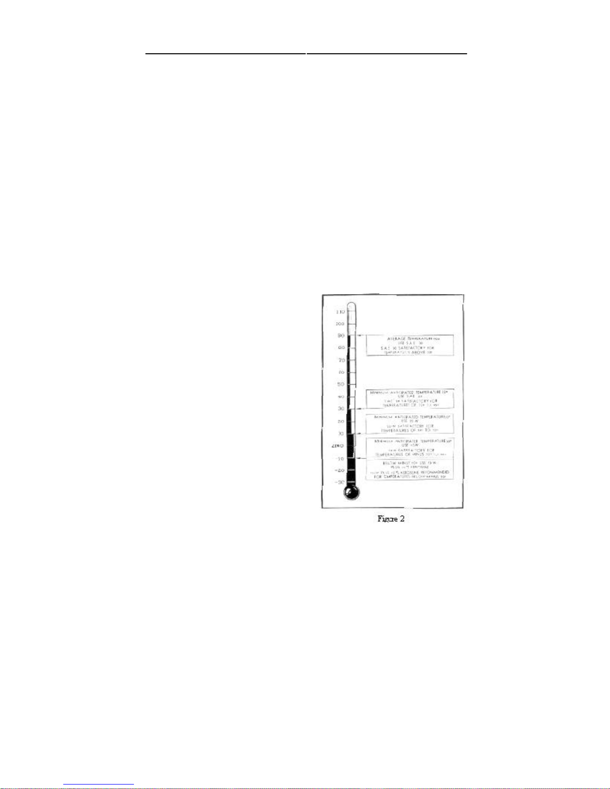
It is most important that the oil should have the ability to flow at low temperatures to
permit easy starting and at the same time, afford adequate lubrication when the engine is
FOR USE
Note: Kerosene should be added only when
HUDSON OWNER MANUAL 15
S.A.E. 30
S.A.E.
20
20 W
10 W.
10 W. plus
10% Kerosene
lubricants.
TYPES OF OIL
American Petroleum Institute, as follows:
this type are generally suitable under moderate driving conditions.
PREMIUM MOTOR OIL—This term is used to designate an oil having proved oxida-
suitable for use where operating conditions are such that regular oils do not give satisfactory service.
gasoline engines under heavy-duty service conditions.
at normal operating temperatures. The oil selected should be based on its ability to perform
these two functions at the lowest anticipated
temperatures expected before the next oil
change period. The following table will be
helpful in making this selection.
90° Average temperature
32º Minimum temperature
10° Minimum temperature
—
10° Minimum temperature
Below —10° temp
temperatures below —10° are expected for
long periods.
Your Authorized Hudson Dealer, who has
had long experience with the brands of oil
available in your locality, will be glad to help
you with your lubrication problems.
Page 18
short persons to sit higher; thus making for better vision. Seat locks in position when lever
(1) DIRECTION INDICATOR LEVER—Push lever upward for right turn and downward
(2) STARTER BUTTON—Pressing button in with ignition switch turned on operates the
starter. On cars equipped with Super-Matic Drive, or Drive-Master, the clutch pedal must
be pushed down before the starter will operate. Do not press button when engine is
(3) DIRECTION INDICATOR LIGHT—Light flashes with front and rear indicator
(4) OIL PRESSURE INDICATOR — Shows red when ignition is turned on and engine
not running. Light should go out when engine is started. If it does not, shut off engine and
(5) FUEL GAUGE—Indicates the level of the fuel in the gasoline tank when the ignition
switch is turned on. When needle reaches "empty" mark, approximately 1-1/2 gallons of
(6) TEMPERATURE GAUGE—Indicates temperature of water or anti-freeze when
ignition is turned on. When ignition is turned off, the pointer returns to the "H" position
16 HUDSON OWNER MANUAL
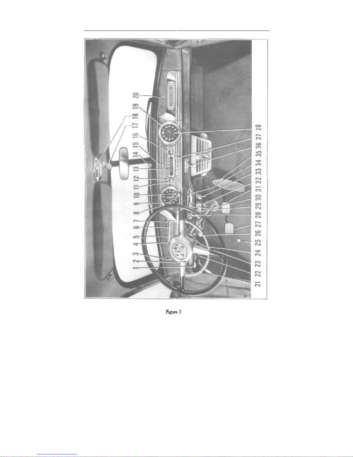
OPERATING CONTROLS
Arrangement and functions of the instruments and controls of your new Hudson have
been planned for maximum convenience and
comfort of the driver, as well as for safety. If
you have driven Hudsons previously or are a
first time Hudson owner, you will want to
know all about the newer controls before driving your new car. We, accordingly, recommend that you read the following instructions
carefully.
SEAT ADJUSTING LEVER —Raising the
lever on the left side of the front seat permits
the seat to be moved forward or backward to
the position most convenient for the driver. As
Figure 4
the seat moves forward, it rises, permitting
is released.
for left turn. Lever returns to "Off" position automatically when turn is completed.
running or car is in gear.
signals.
determine cause.
fuel remains in reserve.
at the right side of the dial.
Page 19
HUDSON OWNER MANUAL 17
Page 20

(7) GENERATOR CHARGE INDICATOR—Shows red when ignition is turned on and
(9) HEADLIGHT BEAM INDICATOR—Shows red when headlight beam is in upper or
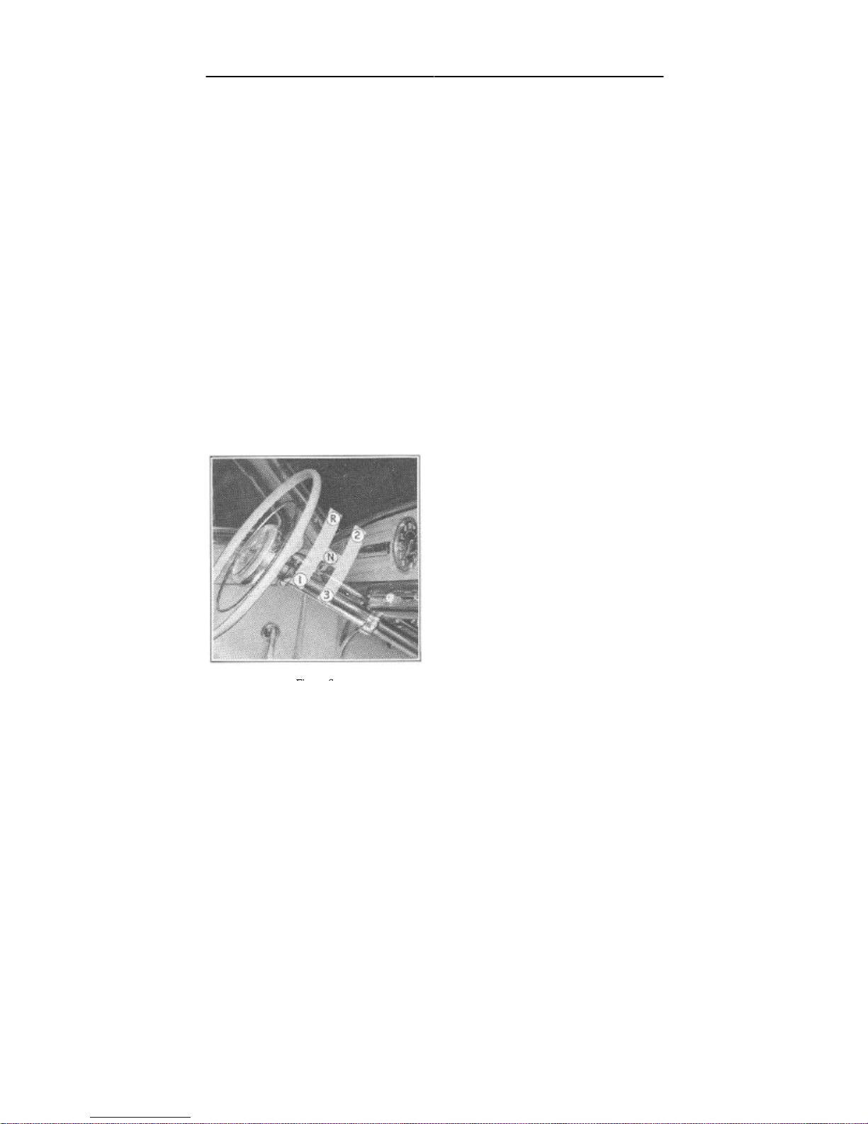
(10) GEAR SHIFT LEVER—Should always be placed in neutral position before starting
engine. Raise knob and move lever forward for reverse gear and rearward for low gear.
Move lever to neutral, depress and slide forward for second gear and rearward for high
(11) RADIO ON AND OFF AND VOLUME CONTROL KNOB—Off in extreme left
position. Turning knob to right turns on radio and regulates volume.
(12) RADIO TONE CONTROL RING—Turning to right from mid- position brings out
(14) WINDSHIELD WIPER CONTROL KNOB—Left position "Off." Turning knob to
right or clockwise turns on and regulates speed of wipers. When car is equipped with a
windshield washer as an accessory, pressing down the button in the center of the knob
(17) RADIO ANTENNA OPERATING KNOB—To raise antenna, press in knob slightly
and turn to right or left one-half turn. To extend antenna, turn knob one-quarter turn, pull
out inner or telescopic section of antenna and turn knob until antenna is in upright position.
18 HUDSON OWNER MANUAL
when engine is running at low speed. Light should go out as speed is increased.
(8) SPEEDOMETER—Includes mileage indicator showing accumulated mileage.
country driving position.
gear. If car is equipped with Hudson Super-Matic Drive or Drive-Master, follow instructions shown under "Drive-Master."
the high notes and to left emphasizes the bass notes. See Radio Owner's Manual.
(13) RADIO STATION DIAL—Indicates station frequency.
supplies solution for washing.
(15) ASH RECEIVER—Sliding drawer type—pulls out.
(16) RADIO MANUAL TUNING KNOB—Turn knob to tune in stations manually.
(18) DOME LIGHT SWITCH—Sliding switch operates front dome light. Rear compartment dome lights operated by sliding switch on right door pillar.
Page 21

(19) CLOCK—Mechanical clock requires winding every day. Turn knob clockwise to
wind. Electric clock requires no winding and is protected by a fuse at the back. On both
(20) LOCKER BOX LOCK—Press in to open door. Locks by inserting key and turning
(21) PARKING BRAKE LEVER—Apply brakes by pulling lever backward and pressing
down brake pedal at the same time. Release brakes by turning handle to right and pushing
(22) HOOD UNLOCKING HANDLE—Pull handle to release lock. Then release safety
catch by reaching finger under louvre at front of hood and pulling lever forward. Grasp
(24) INSTRUMENT LIGHT RHEOSTAT—Controls the brilliance of the instrument
lights. Turning knob to right decreases and to left increases amount of light. Turning knob
(25) HEADLIGHT FOOT SWITCH—Controls country (upper) and traffic (lower)
beams. When meeting oncoming traffic and beam indicator shows red, depress foot switch
once and release for passing beam. Pressing and releasing switch the second time restores
(26) SUPER-MATIC DRIVE FOURTH SPEED CONTROL KNOB OR OVERDRIVE
CONTROL KNOB—Push knob all the way in for automatic operation of fourth speed on
(27) CLUTCH PEDAL—Should be depressed fully to floorboard when starting the
Master, this must be done before pressing the starter button or the starter will not operate.
When starting the engine, particularly in cold weather, depressing the clutch pedal
(28) IGNITION LOCK—Inserting and turning key to right turns ignition on. When
HUDSON OWNER MANUAL 19
types, hands are set by pulling out and turning knob (38).
one-quarter turn to left.
it down as far as it will go.
hood at front end and raise. To lock, lower hood and press down on front end.
(23) HORN OPERATING RING—Press down from any position to operate horns.
to extreme left turns out lights entirely.
light beams to upper or country driving position.
Super-Matic Drive equipped cars or for Overdrive on cars having this equipment.
engine and shifting gears. On cars equipped with Hudson Super-Matic Drive or Drive-
manually will eliminate transmission gear drag and facilitate starting.
lighting switch is turned to first "On" position lock is illuminated.
Page 22
(29) WEATHER-CONTROL HEAT REGULATOR LEVER—Controls water circulating
through heater. Moving lever to right increases and to left decreases temperature. At
(30) LIGHTING CONTROL SWITCH—Controls instrument lights, headlights, hood
light, parking lights, license light and tail lights. Turning knob to first position at right
gives parking lights, hood light, instrument lights, license light and tail lights. Moving
knob to second position to right turns on the headlights in addition to other lights. Turning
ates reserve mechanical system on rear wheels in event of disablement of hydraulic system.
shield and circulating air when car is standing. Extreme left position of knob "OFF." First
position to right provides low speed and extreme right position high speed operation of
tor and pulled back to close it. When Hudson Weather- Control is installed, temperature is
(34) CIGAR LIGHTER—Press in to operate. Automatically pushes out when proper
(35) ACCELERATOR PEDAL —Controls
the speed of the engine and car. Never pump
ing a cold engine, the accelerator pedal
should be pressed half way and released
tion of the gear shifting on cars equipped
Master and Overdrive on cars fitted with this
20 HUDSON OWNER MANUAL
extreme left position heat is entirely shut off.
knob to extreme left position turns off all lights.
(31) BRAKE PEDAL—Controls hydraulic operation of brakes on all wheels. Also oper-
(32) WEATHER-CONTROL SWITCH—Controls operation of fans for defrosting wind-
fans.
(33) COWL VENTILATOR HANDLE—Should be pushed forward to open cowl ventila-
regulated by ventilator opening. (See Weather-Control Instruction Booklet.)
temperature has been reached.
the accelerator pedal when starting the engine as it will result in flooding. When start-
slowly before cranking. (See "To Start Engine.") The accelerator controls the opera-
with Hudson Super-Matic Drive, Drive-
device.
Page 23

Push button "On" for automatic gear shifting. Pushing "Off" button permits
(37) RADIO AUTOMATIC TUNING BUTTONS—Press in button for automatic
(38) CLOCK KNOB—Turn to wind mechanical type clock. Pull out and turn to
Before your new Hudson automobile was delivered to you, your Dealer
checked it over thoroughly to be sure that all adjustments were in order; that all
lubrication fittings and units of the car were properly lubricated; that the
cooling system was filled to the proper level, and that the tires were inflated to
When starting with a cold engine, always keep the speed near 30 until the
engine reaches normal operating temperature. This is good practice at any time
but especially necessary when the engine is new and the moving parts not worn
in. For the first 250 miles keep the speed under 40 but drive as little as possible
under 25. Between 250 miles and 500 miles the top limit may be increased to
At least a third of the mileage of each period should be driven at or near the
maximum speed recommended. Do not drive at constant speed for any length of
time but vary the speed within the recommended limits. At no time during the
first 1000 miles should the throttle be opened fully for quick acceleration or hill
The first 1000 miles are very important to your new engine and a little care
After the first 500 miles of driving return your car to your Dealer to have the
oil changed, as it is good practice to have fresh clean oil in the engine before
starting to drive at the increased speeds permissible during the second 500 miles
The carburetor is fitted with an automatic choke which correctly proportions
HUDSON OWNER MANUAL 21
(36) SUPER-MATIC DRIVE AND DRIVE-MASTER CONTROL SWITCH—
conventional operation of clutch and gear shifting.
tuning of station desired.
set hands on both mechanical and electric type clocks.
DRIVING YOUR NEW CAR
the proper pressures.
50 and between 500 and 1000 miles to 60.
climbing.
during this time will pay off in added economy throughout a longer life.
of the break-in.
STARTING THE ENGINE
the fuel mixture during the starting and warm-up period.
1. Place gear shift lever in neutral position.
2. Depress clutch pedal.
Page 24

22 HUDSON OWNER MANUAL
4. If engine is completely cold from standing for several hours or overnight, depress the
ON CARS EQUIPPED WITH SUPER-MATIC DRIVE OR DRIVE-MASTER THE
CLUTCH PEDAL MUST BE DEPRESSED OR THE STARTER WILL NOT
OPERATE. After engine has started, it will run at high idle speed for warm-up. When
the engine is warm, a slight depression and release of the accelerator pedal will permit
5. If engine is warm from previous running and has not been standing long enough to
become completely cold, depress the accelerator pedal one-quarter to one-half way
After the engine has been started and the clutch pedal depressed, raise transmission
control lever and move it forward for reverse gear, or rearward for low gear. Move lever
If car is equipped with Hudson Super-Matic Drive or Drive-Master, see Special
If car is equipped with Overdrive, follow Special Operating Instructions, number (26)
CARBON MONOXIDE, A DEADLY, COLORLESS, ODORLESS GAS IS ALWAYS
RAGE DOORS SHOULD ALWAYS BE FULLY OPENED WHEN STARTING OR
When your car was delivered to you, it was provided with two sets of keys. The keys
with round handles fit the ignition and both front door outside locks. The keys with the
All keys are numbered and these numbers should be registered on your Owner
Identification Card, as well as some other suitable place where they will be available
should the keys become lost. As insurance regulations prohibit the stamping of the key
3. Turn on ignition switch.
accelerator pedal at least one-half way and release slowly, then press starter button.
the throttle to return to normal idle.
and hold in this position while cranking.
TO START CAR
to neutral, depress and slide it forward for second gear, or rearward for high gear.
Operating Instructions, number (36) listed under "Operating Controls."
listed under "Operating Controls."
CARBON MONOXIDE GAS
PRESENT IN THE EXHAUST OF THE INTERNAL COMBUSTION ENGINE. GA-
RUNNING THE ENGINE.
LOCKING YOUR CAR
octagonal shaped handles fit the locker box door and rear compartment locks.
Page 25

HUDSON OWNER MANUAL 23
position, then operate outside or inside door han-
Doors cannot be opened from inside or outside unless inside safety buttons in garnish
Figure 7
numbers on the lock cylinders, misplaced or lost keys can be obtained from your Hudson
Dealer only by referring to key change number.
Many cars are driven away by unscrupulous persons simply because the ignition key
was left in the lock. Make it a practice to remove the key from the lock if the car is to be
left unattended even for a few minutes
DOOR LOCK OPERATION
TO OPEN DOORS
FROM OUTSIDE—Outside door handles are of
the stationary type, fitted with a push button at the
end. To open the door, grasp the handle and press
in the push button with the heel of the hand or the
thumb. Push door to close.
Caution: Door will not close if latch bolt
has been moved upward from lower end of
curved slot in door. To return latch bolt to
lower end of slot, lift inside safety button to "up"
dle.
FROM INSIDE—Front doors—rotate inside handle (43) by pulling backward. Rear
doors—rotate inside handle by pressing down.
mouldings are in the "up" position.
Figure 8
Page 26

24 HUDSON OWNER MANUAL
time. Spring loaded hinges assist in raising the hood and strong, self-locking supports
TO LOCK DOORS
FROM INSIDE—Push down inside safety buttons (39) in garnish moulding.
WHEN LEAVING CAR—Close windows with doors closed. Push down inside safety
buttons on all doors except the front one from which you are leaving. Close front door
and turn lock with key until inside safety button is "Down." Turn key back to
vertical position and remove.
LOCKER BOX DOOR
To lock the door, turn key one-quarter turn clockwise and remove. To unlock
door, turn key one-quarter turn counter-clockwise and remove.
When door is unlocked, it can be opened by pressing in on lock cylinder face.
REAR COMPARTMENT DOOR
To safeguard the spare tire, tools and any luggage you may be carrying, always
lock the rear compartment door. Turning the key one-half turn counter-clockwise
unlocks the lock. To lock it, turn the key one-half turn in a clockwise direction. To
open, lift the door with the left handle after raising the right handle to release the
catches. To close, lower the door, then raise and lower the right handle to engage
the catches.
LOCKING THE HOOD
The hood of your Hudson car is designed to open at the front and is provided with
a locking arrangement to prevent the battery, engine and accessories from being
tampered with.
The hood lock is controlled by a handle located under the instrument panel on the
left side. Pulling out the handle releases the lock and raises the front end of the
hood slightly to the safety catch position.
The safety catch can then be released by reaching under the louver at the front of the
car and pulling the catch forward and raising the front end of the hood at the same
hold it up.
Page 27

HUDSON OWNER MANUAL 25
plete wheel and tire so as to change
jacked up at a time, always start, by installing
prevent undue tire wear and high speed wheel
To lock, lower the hood and press down at the front end to engage the safety catch
and lock.
TIRES
INFLATION PRESSURES
Maintaining proper tire pressures is the most important factor in obtaining maxi-
mum tire life, proper car handling, and best riding qualities.
Because tires get hot due to road contact and internal friction, the air pressure
may increase considerably after hard driving during hot weather. For this reason, tire
inflation and pressure checking should always be done when the tires are cold.
Ordinarily tire pressures should be checked at least once a week. However, when
touring, or if the car is driven extensively, they should be checked every morning
before starting out.
Tire valve caps should be finger tight to prevent loss of air which may be
escaping from a leaky valve and also precludes the possibility of dust and dirt getting
into the valve. Replace missing valve caps promptly.
Keep tires inflated to the following pressures:
Size Front Rear
7.10 x 15 (Standard)....................24 Pounds......................24 Pounds
7.60 x 15 (Optional)...................24 Pounds......................24 Pounds
MINIMIZING TIRE WEAR
By changing the position of the tires every
2500 to 3000 miles, they will last much longer. It is not necessary to remove the tires
from the wheels but simply switch the com-
the direction of rotation.
To avoid having more than one wheel
the spare wheel and tire first, then follow
through as shown in Figure 11
.TIRE AND WHEEL BALANCE
Proper tire and wheel balance is essential to
tramp, both of which contribute to poor handling, certain riding discomforts both of which
Figure 11
Page 28

26 HUDSON OWNER MANUAL
position, move the other tool around the rim and remove the remainder of the bead. Then
excessive wear of front end parts. Tires and tubes are balanced at the time of assembly at
the factory. The balancing marks are indicated on the tire by a small red mark. Whenever
a tire is removed from the wheel, it should always be reinstalled with the red mark aligned
with the valve stem.
Although tires and wheels are balanced when they leave the factory, subsequent tire
wear causes them to go out of balance. To maintain proper balance and assist in prolonging tire life, it is the tire manufacturers' recommendation that the wheel and tire assemblies be checked for balance every 2,500 miles and whenever a tire is repaired or
recapped. Your Authorized Hudson Dealer has the necessary equipment to perform this
work.
DISMOUNTING AND REMOUNTING TIRES
TO DISMOUNT—Deflate the tube completely. Stand on the tire with both feet to force
the bead away. from the rim. Push the valve stem back into the tire. With two tire tools
inserted about eight inches apart between the bead and the rim, raise the bead over the
rim. BE CAREFUL NOT TO PINCH THE TUBE WITH THE TOOLS. With one tool in
remove the tube.
Stand wheel in upright position with inner bead in rim well. Apply liquid soap around
both sides of rim. Insert both tire tools between bead and rim and pry tire out of rim.
TO REMOUNT TIRE—Coat both beads of tire with liquid soap to help slide them over
the rim. Inflate tube just enough to round it out, then insert it in the tire, placing the valve
stem directly in line with the red balancing mark on the tire. Place the tire on the wheel,
carefully guiding valve stem into the hole in the rim. Push the inner bead over the rim and
into well at valve stem and force balance of bead over the rim. It may be necessary to
force a small remaining portion of the bead over the rim with the tire tool.
Insert the tire tool between outer bead and rim at a point opposite the valve stem and
work bead over the rim. Leave tool in place and work other tool around bead and force
remainder of the bead over the rim. BE CAREFUL NOT TO DAMAGE THE TUBE
WITH THE TOOL.
Inflate tire slowly, carefully checking beads to see that they both are seating properly
on the rim. The tire may be centered by bouncing it a few times. Inflate tire to recommended pressure.
TOOL KIT
The tool kit is stored in the rear compartment. It contains a wheel hub bolt wrench
(which is also used as a jack handle), pliers, screw driver, and a ratchet type bumper jack
and base.
SPARE TIRE AND WHEEL
To remove the spare tire and wheel mounted in the rear compartment, take out the
clamp bolt and plate, using the wheel hub bolt wrench.
Page 29

HUDSON OWNER MANUAL 27
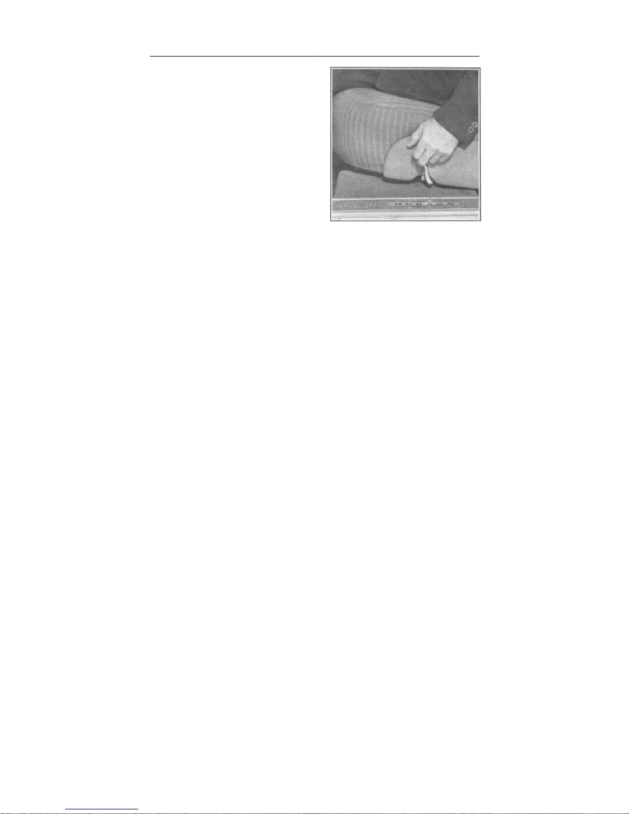
Before raising the car, remove the hub cap with a screw driver and with the hub bolt
wrench (jack wrench) loosen the hub bolts one turn. Raise the car sufficiently to clear the
Your New Hudson is provided with special jack lifting pads built into the frame at
the front and at the sides near the rear, which
assure maximum lifting efficiency and
safety and prevents the possibility of springing the bumpers.
Set the parking brake securely and block
the wheel opposite the one being changed to
prevent any movement of the car. Set the
jack base on a level and solid footing and
engage the lifting lug of the jack in the
socket of the frame pad, as shown. The
wheel bolt wrench is designed for use as a
handle to operate the jack.
When removing a rear wheel, it is neces-
Figure 13
sary to take off the wheel cover which is a
part of the rocker panel opposite the rear
wheel (Fig- 13 ure 14). This can best be done after the car is jacked up, by reaching under
and raising up the loop at each end of the attaching rod until it is clear of its hook, as
shown.
CHANGING THE WHEEL AND TIRE
ground and then remove all hub bolts and take off tire and wheel.
Page 30

28 HUDSON OWNER MANUAL
Hudson Super Six engines are of "L" head design, mounted at three points in live
piston rings.
piston pin bearing.
CAMSHAFT—Nickel-chrome-molybdenum iron alloy, with angular ground cams
When installing the spare, be sure the pilot stud in the hub is in the top position,
then slide wheel onto hub using pilot stud as a guide. After wheel has been installed
and car lowered, again check tightness of hub bolts and replace hub cap.
ENGINES
ENGINE FEATURES—SUPER SIX
rubber cushions to prevent sound or vibration being transmitted to the body.
Figure 15
CYLINDER HEAD—High turbulence type for better fuel combustion.
CRANKSHAFT—Forged in position, fully compensated and equipped with rubber-insulated vibration damper, balanced at rest and in motion: four precision type,
steel-backed, babbitt-lined main bearings.
PISTONS—T-slot, cam ground. aluminum alloy, fitted with four pinned, plated
CONNECTING RODS—Drop-forged, high manganese alloy, with replaceable,
steel-backed, babbitt-lined precision type bearings. Rifle-drilled for lubrication to
for positive rotation of tappet. Heat treated for extreme hardness. Phosphate coated
for better lubrication. Bearings pressure lubricated.
Page 31

HUDSON OWNER MANUAL 29
TAPPETS—Rotating mushroom type with special self-locking adjusting screw.
VALVES—Special alloy. Installed at angle for faster intake and exhaust flow.
Grooved for conical spring seat retainer. Valve seats integral with cylinder block,
CYLINDER BLOCK—High chrome alloy, entire block as hard as ordinary valve
CARBURETION—Direct passage of fuel through radial manifold to combustion
chamber. Dual down-draft type. Automatic choke. Climatic control. Anti-percolator
LUBRICATION—Full pressure lubrication to 40 points. Float type oil intake
Hudson Super Eight engines are of "L" head design, mounted at three points in live
insulated damper, balanced at rest and in motion; five long-wearing, bronze-backed
Pressure lubricated.
cooled around entire surfaces. Exhaust valves are of high nickel-chrome alloy.
seat inserts. Water jackets full length of cylinders and all around each cylinder.
valve.
draws clean oil from point just below top level in oil pan.
ENGINE FEATURES—SUPER EIGHT
rubber cushions to prevent sound or vibration being transmitted to the body.
CYLINDER HEAD—High turbulence type for better fuel combustion.
CRANKSHAFT—Drop-forged, fully compensated and equipped with rubber-
main bearings.
Page 32

30 HUDSON OWNER MANUAL
PISTONS—T-slot, cam ground, aluminum alloy, fitted with four pinned, plated
piston rings.
CONNECTING RODS—Drop-forged, high manganese alloy for greater strength,
dowel-fitted caps assure perfect alignment. Bearings with centrifugally installed
CAMSHAFT—Nickel-chrome-molybdenum-iron alloy, heat treated for maximum
TAPPETS—Exclusive roller cam design. Rotating cam lobe maintains constant
VALVES—Special alloy steel. Exhaust valves have high chrome content to resist
CYLINDER BLOCK—Super-hard chrome alloy. Provides wear resisting cylinder
bores, eliminates need for special valve seat inserts. Entire block is as hard as ordinary
CARBURETION—Down-draft type. Dual flow to combustion chambers for more
complete combustion. Radial intake manifold provides direct, free flow passages for
LUBRICATION—Exclusive Duo-Flo supplies oil in direct ratio to engine
speed. Lubricates every part at first turn of crankshaft. Float type oil intake draws
Correct valve tappet adjustment is vital to good engine operation and it is important,
therefore, that the specified clearance between the adjusting screws and valve stems
Tappets checked and adjusted only after the engine has been run long enough to
The cooling system is of the pressure type, employing a cellular, tubular radiator,
The water pump has a large six vane impeller and the shaft is mounted on a double
row ball bearing with grease sealed in and requiring no lubrication attention. A new
type spring loaded bellows seal and composition thrust washers prevent leakage
babbitt metal.
hardness, specially treated for smooth finish. Large babbitt bearings.
contact, requires less adjustment, wears longer.
high temperatures.
valve seat inserts.
fuel mixture. Automatic choke. Climatic control. Anti-percolator valve. Air cleaner.
clean oil from point just below surface of oil in pan.
VALVE TAPPET ADJUSTMENT
be maintained at all times. These are as follows:
Six Cylinder Engine Eight Cylinder Engine
Intake Valves .008" .006"
Exhaust Valves .010" .008"
attain normal operating temperature. Be sure to use an accurate feeler gauge.
The valve locations, counting from the front of the engine, are as follows :
Six Cylinder Engine Eight Cylinder Engine
Intake Valves 2-4-5-8-9-11 2-3-6-7-10-11-14-15
Exhaust Valves l-3-6-7-10-12 l-4-5-8-9-12-13-16
COOLING SYSTEM
centrifugal pump and four blade fan.
around the shaft.
By-pass type thermostats are used which permit quick engine warm-up by restricting
Page 33

HUDSON OWNER MANUAL 31
Models 501, 502, 503 and 504 use a special radiator cap which is designed to
maintain a slight pressure in the cooling system. It is important that this cap is always
CAUTION: When removing the filler cap while the engine is hot, always turn cap
slowly until the stop is reached. Keep the cap in this position until all pressure has
TO DRAIN the radiator only, turn handle of the drain cock located at the lower
right corner of the radiator, counter-clockwise. To drain the complete cooling system,
NOTE: If it becomes necessary to drain the radiator when it contains anti-freeze and
it is desired to save it, a piece of hose may be fitted over the end of the drain cock and
PROPER CARE of the cooling system is highly essential to maintain efficient
engine operation. Rust and scale in the cylinder block is a natural product of water and
iron. Therefore, unless the necessary precautions are taken to prevent this
accumulation, which acts as an insulator, so- called "hot spots" may result through the
The use of Hudson Rust and Corrosion Inhibitor in the cooling system prior to
adding anti-freeze in the fall and after draining in the spring will assist to a large
measure in keeping the system clean and permit efficient circulation. This product is
The fan belt is of the "V" type and drives the water pump and generator through the
Figure 17
warm-up by restricting the coolant circulation through the radiator and by-passing it
around the cylinder block. The thermostat
begins to open at temperatures of from 150
to 155 degrees and is wide open at 185
degrees.
A large 4 blade fan, with blades unevenly
spaced to minimize sound, is used.
COOLING SYSTEM CAPACITY
6 Cylinder Models — 19 Qts.
8 Cylinder Models — 17 Qts.
Cars equipped with heater require one
additional quart. Maintain level within 1/2"
of the overflow when using water and
within 3A" of overflow when using antifreeze.
RADIATOR CAP
turned down tightly to maintain the correct pressure.
been released, then turn cap fully to the left and remove.
also remove the pipe plug located at the left rear corner of the cylinder block.
the loose end placed in a container.
inability of the water to cool the cylinders and the area adjacent to the valve seats.
available through all Authorized Hudson Dealers.
FAN BELT
vibration dampener pulley.
Page 34

32 HUDSON OWNER MANUAL
Figure 18
The belt is adjustable by means of a swinging generator mounting. Moving the
generator away from the engine increases the belt tension while moving it towards
the engine decreases its tension. Belt adjustment is correct when it is possible to
depress the belt approximately 3/4", as shown in the illustration.
Adjustment is made by loosening cap screws and nuts (D), (E) and (F). When
proper position has been obtained, be sure to tighten screws and
nuts
securely.
ANTI-FREEZE
Before installing any anti-freeze when preparing for winter operation, it is good
practice to always drain and flush the cooling system to insure unrestricted circulation. Also carefully check all hoses and gaskets for leaks or signs of deterioration.
Avoid the use of anti-freeze solutions containing calcium salts, or other ingredients which promote electrolytic action. Glucose and honey clog the radiator;
kerosene and fuel oil when hot, expel inflammable vapors and, therefore, solutions
containing these ingredients should never be used.
The following anti-freeze table will be helpful in determining the quantity of antifreeze required for proper protection:
Tempera-
ture
+20
0
+10
0°
—10°
—20°
°
—30
Quarts
Ethalene Glycol
(Prestone or Equivalent)
U.S.
3
4-1/2
6
7
7-3/4
8
Imp.
Quarts
2-1/2
3-3/4
5
6
6-1/3
6-1/2
Metric
Liters
2-3/4
4-1/4
5-1/2
6-1/2
7-1/4
7-1/2
Denatured Alcohol
U.S.
Quarts
3
4-1/2
6
7-1/3
8-1/2
9-1/2
Methanol or
Imp.
Quarts
2-1/2
4
5
6
7
8
Metric
Liters
2-¾
4-½
5-½
7
8
9
Page 35

HUDSON OWNER MANUAL 33
tions, varying wind velocity, temperature changes, heavy traffic and frequent stops.
All of these conditions have a direct bearing on the gasoline mileage your car can
give. There are, however, a number of things you can do in driving to improve your
2. Warm up the engine by letting it run idle for a few minutes when starting, to
CARBURETOR AND FUEL SYSTEM
FUEL RECOMMENDATIONS
The engine of your Hudson car is designed to give good performance and
economy with regular grades of gasoline. One of the most important factors in
getting the most out of the fuels available, is correct ignition timing.
The lower grades of gasoline should be avoided in the present day high compression engines, as they tend to cause "pinging" under normal load conditions, which
requires that the spark be retarded for quieter operation. Retarding the spark
naturally affects the performance of the car, as well as economy of operation and,
therefore, no saving in operation is obtained. Also avoid the use of fuels which tend
to gum up quickly as they materially affect the operation of the engine.
Premium grades of fuel, such as Ethyl, which have a higher octane rating. permit
the use of a more advanced spark timing without knock or "pinging." this will result
in improved performance and economy. It should be remembered, however, that
these extra advantages cannot be obtained from this type of fuel unless the spark
timing is advanced.
For information on "Ignition Timing" see pages 39 and 40.
FUEL ECONOMY
Gasoline mileage is the subject of considerable discussion among motorists. We
hear a good deal about the results obtained by certain owners which may cause
others to wonder how the claims are substantiated. Unless we understand the
conditions under which the figures were obtained, they mean very little to us.
There are many factors governing gasoline mileage, such as car speed, road condi-
gasoline mileage.
1. Avoid unnecessary acceleration of the engine.
permit the oil to circulate properly. This is especially important in cold weather.
CAUTION: Avoid racing the engine during the warm-up period.
3. Accelerate slowly.
4. Do not drive in low or second speed gears unnecessarily.
5. Maintain as nearly uniform speed as possible when driving in city traffic.
6. Avoid sudden and unnecessary stops.
7. Keep tires inflated to the recommended pressure.
8. Do not idle the engine unnecessarily.
9. Use engine oil of the proper viscosity.
10. Keep your car properly lubricated.
Page 36

34 HUDSON OWNER MANUAL
The thermostatic housing spring which is contained within the thermostat housing (C),
is calibrated to hold the choke valve closed at a temperature of 75° F. when it is set at the
factory. As the engine warms up the hot air the hot air drawn into the thermostat
11. Have the engine of your car tuned up by your Authorized Hudson Dealer each
5,000
miles. He will check its operation and make any necessary adjustments, including
ignition timing, contact points, spark plugs, valve adjustment and other important
details which have a direct bearing on operating economy.
CARBURETORS
The carburetors are of the dual down-draft, automatic choke type, incorporating
vacuum controlled metering rods, anti-percolator valve, accelerating pump, and fast idle
features. A filter screen is also incorporated at the fuel inlet to prevent the entrance of
foreign particles which would otherwise clog the small drilled passages and jets in the
carburetor.
ADJUSTMENTS—There are no adjustments on the carburetor that will affect high
speed operation. Therefore, any servicing the carburetor may require, other than minor
adjustments that affect operation at idle speed only, should be performed by your
Authorized Hudson Dealer who has the special tools and gauges required to service
these units.
IDLE MIXTURE ADJUSTMENT—
This adjustment is made by turning both idle
adjusting screws (A). The normal position of
these screws is 1/4 to 1 turn off their seats.
To adjust them, turn both screws into their
seats and then out exactly 3/4 of turn. Readjust for smooth idling. Turning the screws in
a clockwise direction produces a leaner mixture and turning them in a counter-clockwise
direction results in a richer mixture.
THROTTLE ADJUSTING SCREW
(B)—controls the engine idle speed. This
screw should be adjusted to give a speed of
7-1/2 to 8 miles per hour in high gear.
NOTE: Before making the idle Mixture
Figure 19
and Throttle Adjusting Screw Adjustments,
be sure the engine has been run long enough
to reach normal operating temperature. Never make these adjustments when engine is
cold.
If these adjustments do not produce satisfactory results, the engine may require an
Engine Tune-up and you should consult your Authorized Hudson Dealer.
AUTOMATIC CHOKE CONTROL—automatically proportions the fuel and air
requirements for both starting and engine warm-up.
housing
Page 37

HUDSON OWNER MANUAL 35
5. Install cleaner on engine and tighten clamp screw. Do not tighten excessively, as
through a pipe passing through the exhaust manifold, causes the thermostatic coil
spring to release its tension on the choke valve, permitting it to open gradually. Thus
as the engine temperature increases, the choke valve gradually opens, resulting in a
leaner mixture being fed into the engine to meet operating requirements.
Any service required on the Automatic Choke should be referred to your Autho-
rized Hudson Dealer.
MANIFOLD HEAT CONTROL VALVE—is automatic and requires no adjust-
ment.
FILTER SCREEN CAP (D)—should be removed and the screen cleaned every
2,000 miles.
CARBURETOR AIR CLEANERS
THE OIL WETTED type air cleaner is used as standard equipment on all models.
In this type cleaner the wire gauze is oil soaked and as the air passes through it,
foreign particles are removed, thereby permitting only clean air to enter the carburetor.
At periods of 2,000 miles, or oftener if local conditions warrant, the filter unit
should be taken out by removing wing nut and lifting off cover. Clean off old oil and
dirt by dipping it in kerosene. Blow it dry and re-oil by dipping it in engine oil, using
the same grade as used in the engine. Permit excess oil to drain off and reinstall it in
the cleaner.
The OIL BATH air cleaner is available as
an option or may be installed by your Authorized Hudson Dealer. In this unit, dirt is
washed out of the air by the oil spray created
as the incoming air strikes the oil in the sump.
The oil bath type air cleaners should be
serviced at 2,000 mile intervals or more
frequently during severe dust conditions, as
follows:
SIX CYLINDER ENGINES
1. Loosen long clamp screw at base, lift up
and take off cleaner.
2. Remove wing nut at top of cleaner,
take out upper section and wash filter
element in gasoline.
Figure 20
3. Remove old oil, wash out cleaner base
and refill to level indicated with new oil of grade as used in engine.
4. Replace upper section of cleaner without oiling filter element and tighten wing
nut.
this may distort carburetor air horn.
6. Remove oil filler pipe air cleaner and wash in gasoline.
Page 38

36 HUDSON OWNER MANUAL
chanically operated diaphragm type
and should he serviced at 2,000 mile
intervals by cleaning the bowl and
shield wiper action under wide open thottle
To clean the gasoline filter screen, which is
recommended every 2,000 miles, remove the
lower cap screw (A) and bowl (B). Before
replacing screen (C) and bowl gasket (D),
Figure 21
Figure 23
Figure 22
FUEL PUMPS
The standard fuel pump is of the me-
screen.
This is done by removing the bowl
screw "A", which in turn permits the
removal of the bowl "B," screen "C"
and gasket "D." Clean and carefully
inspect screen and gasket and replace
them if necessary before reassembling.
EIGHT CYLINDER ENGINES
1.Unscrew and remove wing bolt at top of
cleaner.
2. Remove lower section of cleaner by pulling
it outward toward the left side of the car.
3. Lift out filter element, clean in gasoline and
drain.
4. Remove old oil, wash out base, and refill to
level
indicated with new oil of the same grade as
used in engine.
5. Place filter element and container in posi tion without oiling and install lower section
of cleaner with the dirt shield facing
the front of the car.
6. Install and tighten wing bolt.
COMBINATION FUEL AND
VACUUM PUMP
This type of pump assures steady wind-
operation when engine vacuum is low.
carefully examine them and renew if neces-
sary.
Page 39

HUDSON OWNER MANUAL 37
plished by removing top cover screw (E) and cover (F). Before replacing the
screen and cover, carefully examine screen (G) and gasket (H) and renew if
The electrolyte level in the battery should be maintained at opening above the top
The term "hot" means after the engine has been run about 15 minutes at a speed
Figure 24
The air filter screen should also be cleaned at 2,000 mile intervals. This is accom-
necessary.
STARTING, LIGHTING AND IGNITION
BATTERY
The battery is located in the left front corner of the engine compartment, where
it is easily accessible for servicing.
It is of the 51 plate type, 120 ampere
hour capacity and has the positive post
grounded.
REGISTRATION — So that you may
receive the full benefits of the battery
manufacturer's Guarantee and Adjustment Policy, which covers the battery, be
sure your dealer has registered the battery with the National dealer. If not, this
should he done within thirty (30) days
after you have taken delivery of your car.
CARE — The battery is protected
from being overcharged by a voltage
regulator. At intervals of 5,000 miles,
when the engine is tuned up, the regulator
will be checked for voltage setting.
of the plates.
At least twice a month in warm weather and once a month in cold weather, the
level should be checked and distilled water added to restore it to the proper height.
When adding water in cold weather, do so immediately before driving the car, or
else run the engine for a short time to insure the distilled water mixing properly with
the battery solution. Unless this precaution is taken, freezing and battery damage
may be experienced.
GENERATORS
The generators used on all models are of the fully ventilated, high output type
with third brush adjustment and voltage regulation. The generator is driven from the
crankshaft through a "V" type, adjustable fan belt which also operates the water
pump.
The maximum output on all models is 44 amperes cold and 38 amperes hot.
Page 40

38 HUDSON OWNER MANUAL
Figure 25
Maximum output is reached at a car speed of
about 35 miles per hour. Adjustment of the
output is dependent on battery voltage and,
therefore, any adjustments required should be
made by your Authorized Hudson Dealer, who
ture bearings should he lubricated every 2,000
miles by applying a few drops of light engine
As special equipment is required to test this unit, and as the cover is sealed in
place, the regulator should never be tampered with. See your Authorized Hudson
The Bendix drive pinion threads should be cleaned occasionally with a brush dipped
in kerosene to remove gum and dirt. Do not oil the threads as the kerosene will
Figure 26
has the proper checking equipment.
LUBRICATION—The front and rear arma-
oil to oilers (A) and (B). Avoid over-oiling.
VOLTAGE REGULATOR
This highly sensitive device automatically
increases the amount of current flowing into the
battery when it is low due to heavy electrical
loads and reduces the current flow when the
battery voltage reaches a predetermined value. This prevents damage to battery and
other electrical units from excessively high voltage.
Dealer if it requires checking.
STARTING MOTOR
The starting motor is located at the rear
left corner of the engine and is operated by
a separate solenoid switch. Control of the
starting motor is by means of a push button
located on the instrument panel to the left
of the steering column. The starter control
is operative only when the ignition switch
is turned on.
A small button located at the rear end of
the solenoid switch is exposed by unscrewing a cap and may be used to permit
cranking the engine when checking ignition timing or changing clutch compound.
LUBRICATION—The front and rear
armature bearings should be lubricated
every 2,000 miles by applying a few drops
of light engine oil to oilers (A) and (B).
Avoid over-oiling.
Page 41

HUDSON OWNER MANUAL 39
Place a few drops of light engine oil in the oil cup (B) every 2,000 miles. At the
same time, apply a few drops of oil to wick (E) at the top of the distributor shaft, to
Remove spark plug from No. 1 (front cylinder), place finger over spark plug hole
and crank the engine until air pressure against the finger indicates that the piston is
coming up on the compression stroke. Then continue cranking slowly until the mark
"U.D.C. 1-6" (six cylinder engines) or "U.D.C. 1-8" (eight cylinder engines) lines up
DISTRIBUTOR
The distributor incorporates an automatic governor advance and in addition, a
diaphragm advance control (A), operated by engine vacuum.
The automatic governor advance provides the proper ignition timing in direct
proportion to engine speed.
The diaphragm advance control provides additional spark advance over the
governor advance, through engine vacuum, for maximum fuel economy. When the
engine is running under light load and engine vacuum is high, the distributor is
rotated to the maximum advanced position. However, under heavy load conditions, as when the throttle is opened for additional acceleration or hill climbing,
and engine vacuum is low, the distributor is rotated to the retarded position to
prevent fuel detonation or• pinging.
LUBRICATION
the contact arm pivot (G) and to the lobes
of the cam (C). CAUTION: Do not overoil.
CONTACT POINT ADJUSTMENT
The distributor contact points should be
clean, smooth and make full contact. The
proper gap adjustment is .020" for the six
cylinder and .017" for eight cylinder
distributor. The points are adjusted by removing the distributor cap and rotor and
cranking the engine until the fiber block
on the contact arm rests on the highest
point of the cam lobe (C). Then loosen
lock screw (F) and turn adjusting screw
Figure 27
(D) until the correct gap is obtained. Tighten lock screw and recheck the gap.
IGNITION TIMING
with opening in the rear engine support plate, as shown.
Page 42

40 HUDSON OWNER MANUAL
The engine can be cranked by removing
The distributor rotation is clockwise.
Loosen the distributor advance arm screw
wise to the limit of the slot in quadrant.
Take off the distributor cap and remove the
central wire from the cap. Place the bare
end 1/8" from the cylinder head. Turn on
the ignition and rotate the distributor body
counterclockwise slowly just until a spark
jumps from the high tension wire to the
cylinder head. Tighten screw (I), replace
central cable in cap, and clamp cap on
With the distributor cap in position, the metal strip on the rotor should be directly
in line with No. 1 terminal. The cables should be in the cap terminals in the order,
The foregoing is approximate normal timing for regular or non-premium fuels at
When Ethyl or premium fuels are used in place of the regular or non-premium
grades, a more advanced spark timing should be used and final tests should be made
on the road. Also when operating a car at high altitudes, it will be found that a more
To determine proper spark timing for these conditions, with engine at normal
operating temperature, accelerate at full throttle from 10 trifles per hour in high gear.
A "ping" should be noted at approximately 15 miles per hour. If no "ping" is heard,
clockwise direction one graduation mark at a time until the "ping" is heard. Under no
circumstances, however, should the pointer on the rear engine support be more than
If the "pinging" is heard at speeds above those previously mentioned, retard the
spark timing by loosening the clamp screw and rotate distributor body in opposite
Figure 28
the knurled cap on the starting motor solenoid and pressing the button in quick succession.
(I) and rotate the distributor housing clock-
distributor.
1-5-3-6-2-4 or 1-6-2-5-8-3-7-4, following in a clockwise rotation.
or near sea level. For final setting see "Fuel and Altitude Compensation."
FUEL AND ALTITUDE COMPENSATION
advanced spark timing can be used than at or near sea level.
loosen the distributor quadrant screw (I), and rotate distributor body in a counter-
1 inch (on 1st short mark) before the U.D.C. l-6 or U.D.C. 1-8 mark on flywheels.
direction, one graduation mark at a time until the proper setting is obtained.
Page 43

HUDSON OWNER MANUAL 41
Hudson cars employ the headlighting system known as "Sealed Beam," in which the
light source, the reflector, the lens, and the gasket are all assembled in one securely sealed
2. A traffic (lower) beam is also provided and is low enough on the left side to avoid
glare in the eyes of oncoming drivers. It should always be used when meeting other
vehicles. This beam is designed so that it does not throw any dazzling light into the eyes
bution of light is such that the right side of
the road is illuminated as far ahead as is
By turning the lighting switch knob on
instrument panel to first position, the parking
lights, instrument lights, bonnet light, license
light and tail lights are turned on. Turning
the knob to the second position turns on
these lights in addition to the headlights. The
country (upper) or traffic (lower) headlight
beams are obtained by pressing the foot
When the country (upper) beams are
lighted, a red pilot bulb in the speedometer
dial will be illuminated, making it convenient
for the driver to determine when this beam is in use. Always use the traffic (lower) beam
HEADLAMPS
unit. When the filament burns out or the lens
break, the entire unit is discarded and a new
one installed, thereby assuring maximum
lighting efficiency throughout the life of the
car. "Sealed Beam" headlamps provide two
separate and distinct beams.
1. A country (upper) beam is provided to
illuminate evenly for a considerable distance
ahead of the car. This beam is for use on the
open highway when no other vehicles are
approaching.
Figure 29
of the approaching driver under any condition of car loading. At the same time distri-
practical without causing glare on curves.
Figure 29
when meeting oncoming traffic.
switch.
Page 44

42 HUDSON OWNER MANUAL
To obtain the maximum results in road illumination and the safety that has been
Place the car on a level position with a light-colored vertical screen 25 feet ahead.
For best road lighting results, draw a horizontal line (A-A) on this surface at a level of
If, however, your state requires a loading allowance, draw this horizontal line below
the above mentioned line by the amount required by your particular state. Sight
through the center of the rear window to the right and left of the windshield center bar
and mark two points on the horizontal line. A point midway between these points
To Service Unit:
1. Remove headlamp lens rim by taking out
the three screws.
2. Loosen, but do not remove, the three screws (B)
holding the retaining ring. (Do not disturb the
aiming screws (A and C) at the top and left side
of the unit.)
3. Remove retaining ring by rotating counter-clock
wise, allowing the reflector unit to be removed.
4. Remove the reflector plug from the reflector
unit.
5. Install new unit by reversing above oper-
ations.
Figure 31
"SEALED BEAM" HEADLAMP AIMING ADJUSTMENT
built into the headlighting equipment, the headlamps must be properly aimed.
a point three inches below the headlamp center.
represents the center
Page 45

HUDSON OWNER MANUAL 43
line (car axis) on the screen. Next draw vertical lines (B-B) and (C-C) on the screen
Place lighting switch in the position which produces the country (upper) beam
(bright light). When the country (upper) beam is lighted the lower filaments on both
Independent adjustment of both horizontal and vertical aim is provided in "Sealed
Beam" headlamps, with the adjustment screws accessible from the front of the lamp
after first removing lens rim. The vertical adjustment screw is shown at (A) and the
horizontal adjusting screw at (C). The light beam is moved to the right or left by
tightening or loosening the horizontal adjusting screw (C). The beam may be raised
Cover one lamp to obscure the beam of light and then adjust the beam from the
other lamp so that the center of the zone of highest intensity falls on the intersection
of the horizontal line (A-A) three inches below the lamp center and the vertical line
directly ahead of the lamp. Repeat the operation for the other lamp. No further
A circuit breaker incorporated in the lighting switch and an auxiliary circuit breaker
mounted on the instrument panel protects the lighting and other circuits against
damage in the event of a short or other derangement in the electrical system. Separate
fuses are also employed for the protection of optional equipment and accessory items,
The Electric Clock—has
a 3 ampere fuse contained in the fuse case located at the
Weather-Control—is
protected by a 14 ampere fuse located in a fuse case on the
Radio—includes
a 14 ampere fuse contained in the fuse case incorporated in the
Drive-Master—is
protected by a 10 ampere fuse located in the Drive-Master control
Direction Indicator—has
a fuse of 10 ampere capacity located in a fuse case
sively in Hudson cars to assure smooth engagement. Long life is assured through
triple sealing the unit against fluid loss. Heat developed within the clutch is kept at a
The only attention required is lubrication and a periodic check of the pedal-to-floor
to the right and left of the center line at a distance equal to one-half of the center-tocenter distance between the two headlamps.
lamps are illuminated.
or lowered by turning the vertical adjusting screw (A).
adjustment is needed for the traffic (lower) beam.
CIRCUIT BREAKERS AND FUSES
as follows:
back of the clock.
left side of the heater housing.
"A" lead wire.
switch on the instrument panel.
attached to the flasher unit lead wire.
CLUTCH
A Fluid Cushioned Clutch incorporating a single cork-insert disc, is used exclu-
minimum through proper ventilation and the constant bath of fluid within the housing.
board clearance to insure full travel of the clutch pedal.
Page 46

44 HUDSON OWNER MANUAL
Figure 33
Page 47

To assure full disengagement of the clutch to prevent clashing when shifting gears and
also to prevent the clutch pedal from riding against the floor board, 112" clearance must
Every 5,000 miles the clutch should be drained and refilled with HUDSONITE
CLUTCH COMPOUND, which is produced in the Hudson Engineering Laboratories, and
is available through all Authorized Hudson
Dealers. The exclusive use of this compound
is your assurance of obtaining smooth, even
The clutch is drained without disturbing
the flywheel guard by removing hex plug
(A) in the front face of the flywheel. Then
rotate the flywheel until the first star
stamped on the flywheel face appears in
inspection hole over starter motor and allow
the old fluid to drain out. Turn flywheel until
filler hole reappears and refill with 1/3 pint
of HUDSONITE CLUTCH COMPOUND.
HUDSON OWNER MANUAL 45
CLUTCH PEDAL ADJUSTMENT
be maintained between the floor board and rear face of pedal.
This can be adjusted by loosening lock nut
(A), removing cotter pin and clevis pin (C),
and turning yoke (B) to increase or decrease
the clearance as required. Replace clevis pin
and cotter pin and tighten lock nut securely.
LUBRICATION
The clutch throwout bearing should be
lubricated every 1,000 miles, using viscous
chassis lubricant applied through the grease
fitting on the right side of the clutch housing.
The clutch pedal shaft bushings should also
be lubricated at intervals of 1,000 miles, using viscous chassis lubricant applied through
Figure 31
the grease fitting on the bottom of the pedal,
reached from underneath the car.
clutch action.
Replace plug and tighten securely.
Page 48

The transmission is fitted with one drain plug located at the bottom of the case and one
Remove the filler plug every 1,000 miles and check fluid level. Permit car to stand idle
a few minutes before checking the level. This will allow the foam to subside and assure a
46 HUDSON OWNER MANUAL
TRANSMISSION
The transmission is of the synchronized design, incorporating the "blocker type"
synchronizing unit, which assures an absence of gear clashing when shifting. It provides three speeds forward and one reverse. All gears are of helical cut tooth design
for quiet operation in all speeds.
Figure 36
Gear shifting is accomplished by a steering column gear shift lever. The four
speeds are in the conventional "H" plate order. When in neutral the shift lever is in a
horizontal position in the second and high rail. To shift into reverse gear. the lever
must be raised and moved forward. Movement to low gear is by pulling the lever
backward in the same rail. The shift into second gear is forward to neutral position,
then press lever down and move forward. Moving the lever backward gives high
gear position.
LUBRICATION—STANDARD TRANSMISSION
filler plug on the right side.
check of the actual oil level.
At intervals of 5,000 miles the oil should be drained and the transmission refilled with
new lubricant. In summer use 2 pounds of S.A.E. 90 E.P. gear oil and in winter use an
Page 49

HUDSON OWNER MANUAL 47
As the same grades of gear oil recommended for the transmission are used in the Overdrive,
communicating passages are provided between the two units. Separate drain and filler plugs
are also provided in the Overdrive housing. The drain plug is located on the bottom and the
To check fluid level, first remove Overdrive filler plug and determine level, which should be
even with lower edge of hole. If level is low, refill to correct level. Then check oil level in
To drain and refill, first be sure lubricant is warm as it will flow more freely. Remove both
drain plugs and drain all old lubricant. Replace plugs. Refill Overdrive first, permitting level to
come up to bottom of filler plug hole. Next refill transmission to bottom of level of the filler
plug hole. Replace both plugs.
Should it be necessary to thin the lubricant to facilitate shifting in extremely cold weather,
drain out 2-1/2 ounces of lubricant, add 2-1/2 ounces of kerosene and then refill to proper level
Hudson Super-Matic Drive provides automatic shifting through three forward
An ultra low gear is also provided for adverse conditions while the automatic fourth
speed is higher than direct drive giving reduced engine speed for smooth, economical
With the Super-Matic "On" button (36—Fig. 5) pushed in, the automatic fourth
speed knob (26—Fig. 5) pushed in and shift lever (10— Fig. 5) in driving position,
To start the car forward, start the engine (see "Starting the Engine," Page 21), place
the gear shift lever (10—Fig. 5) in the third gear position. Depress the accelerator
pedal and the car will move forward in accelerating gear.
When the car has been accelerated to the desired speed (above 14 miles per hour)
momentary release of the accelerator pedal will permit the shift into the third gear and
at speeds above 20 miles per hour again releasing the accelerator pedal permits the
When slowing down, the transmission will automatically shift down to third gear
when the car speed drops to 18 miles per hour and to accelerating gear when the
speed reaches 10 miles per hour so that the proper ratio for easy maneuverability and
S.A.E. 80 E.P. grade. If the unit is flushed out, it should be refilled with 2-1/4 pounds of
the proper lubricant.
Should hard shifting be encountered in extremely cold weather, drain out 2 ounces of
transmission oil, add 2 ounces of kerosene and refill to proper level with oil.
LUBRICATION—TRANSMISSION WITH OVERDRIVE
filler plug is on the right side of the housing.
transmission and refill as required.
with oil.
HUDSON SUPER-MATIC DRIVE
speeds yet gives the driver complete control of shifting at every speed.
operation.
the driving of the car is controlled entirely by the accelerator pedal (35—Fig. 5).
OPERATION
shift into fourth gear.
fast acceleration is always available.
Page 50

If rapid acceleration is desired above twenty miles per hour the shift is made from
fourth to third gear by depressing the accelerator fully. When the desired speed is
reached fourth gear is again engaged by momentarily releasing the accelerator pedal.
To use low gear, bring the car to a stop, move the shift lever to neutral and hesitate
momentarily, lift and pull down to low gear position. Depress the accelerator to move
the car forward. If it is desired to continue forward through the automatic gears
simply release the accelerator pedal, move the shift lever to the third gear position and
proceed.
To use reverse, bring the car to a stop, move the shift lever to neutral and hesitate
momentarily, then lift and push up to reverse position. Depress the accelerator pedal
If steep grades are anticipated it is recommended that the fourth speed be locked
out, both for better hill climbing while ascending and more braking effect from the
engine while descending. This can be done by pulling out the Automatic fourth speed
knob while the car is standing or moving forward at speeds below 18 miles per hour.
At speeds above 18 miles per hour it is necessary to depress the accelerator pedal to
the floor to revert to third gear before the automatic fourth speed knob can be pulled
out. This latter obviously should not be attempted while descending a steep grade or
When on extremely steep down grades and still more braking effect of the engine
is desired, depress the clutch pedal, move shift lever to second gear position, release
Automatic shifting can again be obtained by pushing the Super-Matic "On" button
and moving the shift lever to the third gear position and automatic fourth can again
Adverse Driving—When driving on ice, in deep mud or other conditions which
might make it desirous to stay in a particular gear, move the shifting lever to neutral,
push the Super-Matic "Off" button and pull the Automatic fourth speed knob fully
out. Proceed to drive using the clutch, gear shift and accelerator pedal as with any
Hudson Drive-Master provides automatic gear shifting in two forward gears for all
normal driving while a low gear is provided, without necessity of using the clutch
pedal, for adverse driving. Reverse shift can also be made without the use of the
clutch pedal or the car can be operated in the conventional manner with manual
To start the car forward, start the engine (see "Starting the Engine," Page 21), place
the gear shift lever in the high gear position (10—Fig. 5). Depress the accelerator
When the car has been accelerated to the desired speed (above 14 miles per hour),
48 HUDSON OWNER MANUAL
and the car will move to the rear.
MOUNTAIN DRIVING
while following closely behind another vehicle.
clutch pedal then push Super-Matic "Off" button to prevent free-wheeling.
be obtained by pushing the automatic fourth speed button in whenever desired.
standard gear shift
car.
HUDSON DRIVE MASTER
operation of the clutch pedal
and gear shifting lever.
OPERATION
pedal and the car will move forward in the accelerating gear.
Page 51

When slowing down the transmission will automatically shift to the accelerating
gear at about 12 miles per hour in preparation for acceleration or starting after a stop.
To use low gear, move the shift lever to neutral, hesitate momentarily, then lift the
shift lever and pull back to low gear position (10—Fig. 5). To use reverse, push up on
shifting lever from neutral to reverse position (10—Fig. 5) and depress the accelerator
If car is being moved forward in low gear and it is desired to revert to the automatic
gears, release the accelerator pedal, move shift lever to third gear position and depress
When rapid acceleration is desired when driving in high gear below 18 miles per
hour, move shift lever to second gear position, release accelerator momentarily and
the transmission will shift into accelerating gear. If driving at speeds above 20 miles
an hour in high gear, the clutch pedal must be depressed and the shift lever moved to
When using the accelerating gear for greater engine braking effort when descending
steep grades, push the Drive Master "Off" button to prevent free-wheeling. Automatic
shifting is again obtained by pushing the "On" button and moving the shift lever to
The Overdrive provides a fourth gear automatically available at speeds above 22
With the Overdrive knob (26—Fig. 5) pushed in start car and accelerate to a speed
above 22 miles per hour. Release the accelerator pedal momentarily and the shift to
When slowing down the shift will be made back to high gear automatically at 18
If it is desired to revert to high gear above 18 miles per hour for rapid acceleration,
depress the accelerator pedal fully. When the desired car speed is reached release the
When driving at speeds below 18 miles an hour with the Overdrive knob pushed
in, the car is free-wheeling and a shift to first or second gear can be made by moving
When Overdrive and free-wheeling is not desired, as in heavy traffic, on icy or
slippery pavements or on steep grades, simply pull the Overdrive control knob out
while the car is standing or moving at less than 18 miles per hour. If a clicking sound
is heard after pulling the knob out, depress the accelerator pedal slightly to bring the
When driving at speeds above 22 miles per hour it is necessary to depress the
HUDSON OWNER MANUAL 49
momentary release of the accelerator pedal will permit the shift into high gear.
to move car backwards.
the accelerator pedal and proceed.
second gear position to obtain the accelerating gear.
high gear position.
TRANSMISSION OVERDRIVE
miles per hour, reducing engine speed and giving maximum fuel economy.
OPERATION
Overdrive is completed.
miles per hour.
accelerator pedal and Overdrive will again become engaged.
the shifting lever to the desired gear without depressing the clutch.
engine speed up to the car speed and the shift will be completed.
accelerator pedal fully to revert to direct drive and then pull out the control knob.
Page 52

The engine power is transmitted to the rear axle through two tubular propeller shafts,
which permits low center of gravity and smooth operation. The front propeller shaft is
supported near the rear end in an annular ball bearing mounted in rubber to absorb any
vibration and noise. Three universal joints of the needle roller bearing type are employed,
one at the front end of the front shaft, one between the front and rear shafts and another at
Each universal joint is provided with means of lubricating the needle rollers through
drilled passages and pressure type grease fittings. The splined sleeve of the middle joint is
also lubricated through a pressure fitting. Viscous chassis lubricant should be applied co
these fittings each 1,000 miles, using a hand gun or a special adapter on the lubricating
The rear axle is of the semi-floating type employing hypoid gears having teeth cut so
that the driving pinion meshes with the ring gear considerably below the center line of the
differential. This design provides quieter operation, increased gear tooth strength and a
lower car floor with minimum raised section for the propeller shaft. High grade alloy steel
is used throughout for gears and shafts and tapered adjustable roller bearings support the
50 HUDSON OWNER MANUAL
Figure
37
PROPELLER SHAFT AND UNIVERSAL JOINTS
the rear end of the rear shaft.
LUBRICATION
hose nozzle, to guard against excessive pressures.
REAR AXLE
differential assembly, drive pinion and the outer ends of the axle drive shafts.
As the axle bearings are accurately adjusted under load at the factory, no further attention should be required. Special equipment is necessary to properly service this unit;
therefore, any adjustments or repairs required should be referred to your Authorized
Hudson Dealer.
LUBRICATION
The lubricant with which the axle is filled at the factory is especially suited for
Page 53

HUDSON OWNER MANUAL 51
Figure 38
Page 54

protection of the gears during the break-in period. This lubricant should be left in the
The level of the oil in the axle housing should be checked every 1,000 miles and if
plug by adding a S.A.E. 90 Multi-Purpose
52 HUDSON OWNER MANUAL
axle for at least the first 10,000 miles.
low, brought up to the level of the filler
Gear Lubricant which has been qualified
under U. S. Army Specification 2-105B.
As all gear oils have a tendency to foam
due to agitation, the car should be permitted to stand about fifteen minutes to allow
foam to subside before checking the level.
Although seasonal changes are not
required it is recommended that the lubricant be removed from the axle housing and
31/2 lbs. (1.5 kgs.) of new Multi-Purpose
Figure 39
Gear Lubricant be installed at least once a
year or every 10,000 miles.
Rear wheel bearings should be removed, cleaned, and repacked every 10,000
miles with 11/2 ounces of milled sodium soap base lubricant. A special puller is required to remove the hubs; therefore, this operation should be performed by your
Authorized Hudson Dealer.
BRAKE SYSTEM
BRAKES
Patented Double-Safe Hydraulic Brakes employing a reserve mechanical system
operating from the same brake pedal, are used.
Figure 40 Figure 41
Page 55

The brakes are of the Bendix Duo-Servo single anchor type, employing wider shoes
and larger wheel cylinders at the front than at the rear for maximum brake efficiency
and smooth stopping. The shoes are expanded at the top or anchor end by the wheel
cylinders, which are actuated by hydraulic pressure exerted by the master cylinder
If at any time, the hydraulic system should fail due to an accident or some other
cause, continued pressure on the foot pedal automatically applies the mechanical
Numerous rubber parts are used in the hydraulic system which makes necessary the
use of brake fluids that are entirely free of mineral oil and other ingredients which are
detrimental to the rubber and may cause swelling and early deterioration. Hudson
to insure proper operation. This should include a check of the mechanical follow-up
To insure proper functioning of the mechanical reserve brake, it is very important
that the clevis at the front end of the pull rod attached to the brake pedal be adjusted
to maintain a clearance of 1-1/4" between the rear end of the slot and the clevis pin at
Brake adjustments should be performed by your Authorized Hudson Dealer.
However, if an emergency arises where the brakes must be adjusted before you can
the brake backing plate, expand shoes against drum with adjusting screw by
moving outer end of tool toward center of backing plate until a heavy drag is
HUDSON OWNER MANUAL 53
through foot pressure applied to the brake pedal.
reserve system on the rear wheels.
BRAKE FLUID
Hydraulic Brake Fluid meets these requirements.
The master cylinder is self-compensating
and should be kept at least half full at all
times. Always wipe off the master cylinder
at the filler plug before removing plug to
check the fluid level.
The hydraulic system must be bled if air
enters the system. A spongy feeling pedal
is usually an indication that bleeding is
necessary.
Have your Authorized Hudson Dealer
Figure 42
inspect your brakes and check the fluid level periodically,
linkage.
ADJUSTMENTS
all times.
reach an Authorized Hudson Dealer, the following adjustment procedure to compensate for lining wear can be used.
1. Jack up all wheels clear of the floor.
2. Be sure hand brake is fully released.
3. Remove wheel backing plate adjusting screw hole covers.
4. At each wheel, with a screw driver or suitable tool inserted through the slot In
noted when wheel is turned by hand.
Page 56

54 HUDSON OWNER MANUAL
5. Back off screw exactly 14 notches at each wheel by moving tool toward outer edge of
Test car for brake balance. If one wheel skids before the others, loosen the adjustment
A major brake adjustment involves a complete inspection of the braking system—shoe
linings, mechanical follow-up, anchor adjustment, and the hydraulic system. This should be
necessary only in the event that an adjustment for normal lining wear does not produce
Hudson Individual Front Wheel Suspension is of the angularly set "wishbone" type, employing
The upper and lower control arms are pivoted at their inner ends to permit each wheel to
move vertically independently of the other as they pass over road irregularities. They are
All front suspension joint grease fittings should be lubricated every 1,000 miles with
viscous chassis lubricant. For the various fitting locations see the "Lubrication Chart" at the
backing plate.
6. Replace hole covers and lower car to floor.
rather than tighten the other screws.
satisfactory braking results.
.FRONT SUSPENSION
large diameter, soft acting coil springs of alloy steel.
mounted in threaded bushings adjustable for wear and fitted with rubber sleeves for protection against dirt and water.
LUBRICATION
front of this book.
Page 57

HUDSON OWNER MANUAL 55
To prolong tire life, and assure easy car handling and maximum safety, it is
essential that proper front end alignment be maintained. Unintentionally striking the
curb a severe blow when turning, parking, or skidding may not cause enough damage
to make it visible to the eye, but will be reflected in the handling of the car at high
CASTER, the backward or forward tilt of the spindle pins at the top. WHEEL
Accurate gauges and carefully calibrated equipment are necessary to check and
correct alignment. Therefore, it is suggested that any service requirements be referred
The front wheel bearings are of the tapered roller type, adjustable to compensate
pin, replace hub caps and lower car to floor.
the bearings should be removed, cleaned and repacked with four ounces of milled
The steering gear is of the worm and triple roller tooth design. The worm revolves
in two adjustable tapered roller bearings. The roller tooth shaft rotates in two bronze
This design provides ease of steering with freedom from frequent adjustments.
MAINTAINING PROPER FRONT END ALIGNMENT
speeds, or in abnormal tire wear.
Proper front end alignment is dependent on proper adjustment of these three factors:
CAMBER, the outward tilt of the front wheels at the top.
TOE-IN, the setting of the front wheels closer together at the front than at the rear.
to your Authorized Hudson Dealer who is best qualified to do this type of work.
FRONT WHEEL BEARINGS
for wear and are adequately sealed against lubricant loss.
ADJUSTMENT — To check for looseness, raise the front end of the car, place
one hand on the top of the tire and the
other hand on the bottom of the tire and
alternately pull with one hand while pushing with the other. If there is excessive
looseness, adjustment should be made as
follows:
Remove outer and inner hub caps (A) and
(B), using a pry. Remove cotter pin holding nut (C). Turn nut to the right until a
slight drag is felt when turning the wheel
by hand. Loosen nut just sufficiently to
permit wheel to turn freely. Insert cotter
Figure 45
LUBRICATION—Every 10,000 miles,
sodium soap base lubricant. Adjust bearings as instructed under "Adjustment."
STEERING GEAR
bushings.
Provisions
Page 58

56 HUDSON OWNER MANUAL
Provisions for adjustments are, however, incorporated, should they be required after
As special equipment is needed to properly service this unit, all operations or
LUBRICATION—Grease fittings are provided at the front and rear ends and these
lower control arm near the steering spindle end and is completely mounted in rubber. It
extensive service.
adjustments required should be referred to your Authorized Hudson Dealer.
LUBRICATION—Every 1,000 wiles, the
oil level in the steering gear housing should
be checked by removing plug. If level is
low, refill to bottom of hole with S.A.E. 90
E.P. gear oil, summer or winter. Be sure
plug is securely tightened.
DRAG LINK
The drag link is fitted with adjustable
bearings at the front and rear ends. Adjustments are required only in the event that
excessive clearance is felt in the bearings
and when steering adjustments are made. As
special equipment is required to adjust the
drag link to its proper relationship to the
Figure 46
steering gear, all operations should be performed by your Authorized Hudson Dealer.
should be lubricated every 1,000 miles with viscous chassis lubricant.
FRONT LATERAL STABILIZER
The front stabilizer is of the dual acting type, connected to each front suspension
Figure 47
Page 59

HUDSON OWNER MANUAL 57
properly tightened.
plied to these points.
frame brackets with pivot bolts cushioned in
frame through threaded, self-adjusting "U"
threaded bushings. The bushing threads are
ber seals. The rear springs of passenger
Figure 49
eliminates front end sway and stabilizes ride on rough roads, in heavy winds and
when making sharp turns.
No service attention is required except to see that the connecting link nuts are
REAR LATERAL STABILIZER
A rear lateral stabilizer is used as standard equipment. One end of this device is
assembled to the frame side member and the other end to the rear axle housing. Its
purpose is to control the horizontal movement of the body and car. It also prevents
Figure 48
lateral shake of the axle under the car on rough roads.
The ends of the steel bar are cushioned in rubber and no lubrication should be ap-
REAR SPRINGS
Rear springs are of long leaf, semi-elliptical design. The front ends are attached to
rubber. The rear ends are attached to the
ype shackles operating in hardened steel,
protected from road splash and dirt by rub-
models are fitted with metal covers.
LUBRICATION—Springs with covers should be lubricated with viscous chassis
lubrication every 10,000 miles.
Page 60

purpose.
should be performed by your Authorized Hudson Dealer.
58 HUDSON OWNER MANUAL
Figure 50
Metal Covers—Lubricate through holes in bottom of cover using special tool for this
Springs without covers must not be lubricated.
Rear shackle bushings are provided with grease fittings and these should be lubricated
with viscous chassis lubricant every 1,000 miles.
Rear spring front pivot bolt bushings require no lubrication.
SHOCK ABSORBERS
Direct double acting hydraulic type shock absorbers are used at the front and rear. The front shock absorbers are mounted axially within the front coil springs
and are cushioned at the upper and lower ends in rubber
grommets.
The rear units are identical in construction to the
front units, except that eyes are fitted at the upper and
lower ends instead of studs and are also cushioned in
rubber. At the upper end they are attached to the frame
cross member, while at the lower end they are assembled to the rear spring clip plates.
The fluid is sealed in the shock absorbers and they
require no further attention, unless a leak should develop. In this event, the faulty unit should be removed for
repair or replacement. As special tools are required to
service these shock absorbers, all shock absorber work
BODY AND FRAME
Figure 51
Page 61

The Hudson ALL STEEL Monobilt BODY-AND-FRAME includes box-type
frame welded together into a single unit. The strength of steel and the permanence of
welding make for rigidity and safety with minimum weight. Outside girders give
bumper protection at rear and at both sides, even outside the rear wheels. Lowered
floors contribute to a low center of gravity, provide ample head room and maintain
Rotary door locks of a new design are used and all doors are fitted with stationary
type outside handles. A push button at the end of the handle operates the lock and
opens the door. When doors are locked, the handle push button moves in and out
The Inside Safety Button 39
in the
tion before the door can be opened by
To Open Door from Outside,
grasp
heel
of the hand
or the thumb
. Push door to
CAUTION: Door will not close if latch
bolt has been moved upward from lower
end of curved slot in door. To return latch
ton to "up" position, then operate inside or
HUDSON OWNER MANUAL 59
Figure 53
BODY AND FRAME
foundation frame of sturdy steel girders with all structural members of body-and-
road clearance.
Figure 52
DOOR LOCKS
freely without actuating the lock.
garnish molding, must be in the "up" posi-
either the inside or outside handles.
handle and push button either with the
close.
to lower end of slot, lift inside safety but-
outside door handle.
Page 62

(2) Close front door and turn lock with key until inside safety button is "down." Turn
Door hinges and strikers are adjustable in both horizontal and vertical positions to
insure proper door operation. The striker must be adjusted to permit the door to close
easily but firmly against the door rubber weatherstrips with the lock fully engaged.
When adjusting the striker, it is important that the lower edge of the opening in which
the latch bolt operates is 1/16 inch above the bottom of the latch bolt. This provides
a slight interference, which is necessary to insure proper engagement of the latch bolt
Friction type ventilator wings are employed on Pacemaker, Super Six and Super
Eight models and crank operated type wings on the Commodore Six and Eight
models. The friction type wing is operated by pressing in the button and turning the
handle (45) upward. The crank type wing is operated by a regulator controlled by a
The door windows on all models are opened and closed by operating the handle
60 HUDSON OWNER MANUAL
Figure 54 (two views)
To Open Door from Inside—
Front Door—Rotate inside (43) handle by pulling it backward.
Rear Door—Rotate inside handle by pressing it down.
To Lock Car When Leaving—
(1) Close windows. With doors closed, push inside safety buttons down on all doors
except the front one from which you are leaving.
key back to vertical position and remove.
Doors must be closed before they can be locked either by the inside safety
buttons or key.
Door Adjustment—
in the slot.
VENTILATOR WINGS
handle (44).
DOOR WINDOWS
(41).
Page 63

The quarter windows on Brougham and Coupe models are operated by crank handles.
See Body Lubrication Chart on inside of cover for body parts requiring lubrication
Your car is finished with high grade hand rubbed lacquer and with a reasonable amount
of care, it should be possible to maintain its original luster for a long time. Constant
exposure to the elements—strong sunlight, rain, snow and dust will cause the finish to
become dull. If at all possible, it is good practice to park the car in the shade if it is to
To remove grime and dirt the finish should be washed frequently and occasionally it
WASHING the car should never be done when car is warm from standing in the sun.
Always wait until the metal has cooled off. If dirt is heavily caked, soak it off first with
cold water, using an ordinary garden hose. Apply Hudson Hurricane Auto Shampoo, as
POLISHING the car is necessary at intervals to provide the finish with a protective
coat. If ordinary washing does not remove the road grime use Hudson Polish and Cleaner.
A more durable, long lasting, high luster finish can be obtained by cleaning the surface
NEVER polish the car in the sunlight or when the metal is warm. Let it cool first. When
cleaning the surface, a slight amount of the color will be seen on the cloth. This, however,
Ordinary chromium plated parts require no other attention than the cleaning they
However, in the winter, when many municipalities use salt or calcium chloride to melt
ice and snow on the pavements, these parts require a great deal more attention to prevent
the finish becoming pitted and corroded. These melting agents are highly destructive to
An application of Hudson Chromium Polish after washing will assist in preserving the
Bumper impact bars that are scratched through the finish should be sprayed with a
coating of clear lacquer or have an application of Hudson Chromium Polish to prevent
HUDSON OWNER MANUAL 61
QUARTER WINDOWS
On Sedans, except Pacemaker series, the windows are pivoted and friction controlled.
LUBRICATION
attention.
CARE OF THE FINISH
remain in one place for any great length of time.
should also be polished.
outlined in directions on container.
with Hudson Liquid Glaze Cleaner and then applying Hudson Liquid Glaze Sealer.
should be no cause for alarm as it is merely the loose pigment being cleaned off.
These cleaners and polishes may be purchased from your Authorized Hudson Dealer.
CARE OF CHROMIUM PLATED PARTS
receive when the car is washed.
this type of finish and it is important that all trace of the salt be washed off each day.
finish and provide added protection to the surfaces.
corrosion lifting off the plating.
Hudson Chromium Polish can be purchased from Authorized Hudson Dealers.
Page 64

portion and rub from outside in toward the center in successive strokes. This will
62 HUDSON OWNER MANUAL
CLEANING FABRIC TOPS
Soiled fabric tops used on Convertible models can be cleaned quite satis-
factorily ifproper instructions are followed.
Hudson Fabric Cleaner, which is available through your Authorized Hudson
Dealer, should be used. Select an area slightly larger than the soiled portion and with
a soft, clean cloth or sponge moistened with Hudson Fabric Cleaner, rub it in
light successive strokes and work toward the center of the soiled area.
CARE OF THE UPHOLSTERY
The same careful attention that you give the upholstered furniture in your
home should be accorded the upholstery cloth of your automobile. Dust and dirt
blown into the car when the windows are open settles in the fibres of the cloth and
its abrasive action tends to wear the cloth and cause an unsightly appearance.
Once a month, it is good practice to brush the upholstery with a whisk broom
or better still, use the portable attachments usually supplied with most household
vacuum cleaners.
CLEANING THE UPHOLSTERY
Spots on the cushions can easily be cleaned off by using the following instructions.
AVOID using hot water and soap unless specifically called for. NEVER use
gasoline, as most brands contain tetraethyl of lead or coloring which is harmful to cloth,
and it is also highly inflammable.
NOTE: When using cleaning fluid to remove spots, use it sparingly. Just dampen a
clean cloth or a sponge with the fluid and select an area slightly larger than the soiled
avoid forming a ring and prevent the spot from spreading.
Hudson Fabric Cleaner referred to herein, is available at all Authorized Hudson
Dealers.
GREASE SPOTS AND OIL
Scrape off all excess grease with a dull knife. Moisten a cloth or sponge with
Hudson Fabric Cleaner and rub spot as directed above.
CHEWING GUM AND TAR
First moisten lightly with Hudson Fabric Cleaner, then scrape off with a dull knife.
Moisten a clean cloth in very hot water, rinse out and nib lightly as directed
CANDY (Except Chocolate)
above. If an oily spot remains after drying, rub it lightly with a cloth moistened
with Hudson Fabric Cleaner.
CHOCOLATE CANDY
Sponge lightly with LUKEWARM water. After drying, rub lightly as directed
above with a cloth moistened with Hudson Fabric Cleaner.
ICE CREAM
Sponge lightly with LUKEWARM soapsuds, using a neutral soap. Rinse with
cold water and allow to dry. If an oily spot remains, rub it lightly as directed
above with a cloth moistened with Hudson Fabric Cleaner.
Page 65

HUDSON OWNER MANUAL 63
BLOOD
Sponge lightly with COLD water. Apply a few drops of household ammonia,
then sponge again with COLD water.
CAUTION: Never use warm water as it will set the stain.
FRUIT AND WINE
Apply a little hot water to the stain. Rub lightly with a cloth moistened with
hot water. Allow it to dry, then rub lightly as directed above with a cloth
moistened with Hudson Fabric Cleaner.
CAUTION: Soap or heat applied to a fruit or wine stain will cause it to set.
COSMETICS
Lipstick and creams may be removed by applying a few drops of Hudson Fabric
Cleaner to the stain and absorbing it quickly with a blotter. Repeat as necessary
until the spot is removed.
SHOE POLISH
Black and tan polish can be removed by rubbing it with a cloth moistened with
Hudson Fabric Cleaner.
White polish can usually be removed by brushing with a whisk broom. If this
does not remove it, moisten the spot with cold water, let it dry, then brush it again.
URINE
Sponge the spot lightly with a cloth dipped in lukewarm soapsuds (neutral
soap) and then rinse well with a clean cloth rinsed in cold water. Next rub the spot
with a clean cloth moistened in a solution of one part of household ammonia
and five parts of water. After a minute, rinse it off with a clean moist cloth.
DOG AND CAT HAIR
Gather the hair together by rubbing the upholstery with a stiff sponge moist-
ened with water. The hair can then be easily picked off.
RUST SPOTS
Clean these spots by sponging with a cloth moistened with lukewarm soapsuds
(neutral soap).
LEATHER AND IMITATION LEATHER
Clean with lukewarm water and any mild soap, such as Castile. Work up a
thin suds on a piece of cheese-cloth and rub over the surface. Wipe off the
surface the second time, using a piece of cheese-cloth dampened with water.
Finish by wiping with a dry cloth.
HUDSON WEATHER-CONTROL
(Optional Equipment)
The Hudson Weather Control, designed and built into the body structure as a
combined ventilating and heating unit, gives maximum comfort with minimum
adjustment of controls.
Page 66

out of the zone of splash, heavy gas fumes and dust concentration from preceding or
(1) As soon as engine temperature gauge hand begins to move to the right (usually
less than one mile after a cold start) open the cowl ventilator. (33—Fig.
(4) If fogging or frosting of windshield and windows occurs when passengers enter
64 HUDSON OWNER MANUAL
Fresh air is brought into the car through the cowl ventilator which is located high,
passing traffic and gives the cleanest air available for passengers inside the car.
Figure 55
Cold Weather Driving
5—Page 17.)
(2) The automatic temperature control
(29—Fig. 5—Page 17) should be set
slightly to the right of center. Move
to right to increase heat— to left to
decrease heat. On Pacemaker models this control is located at the bottom of the heater (2—Fig. 56A).
(3) If car is standing or being driven at
slow or intermittent traffic speeds,
turn blower control (32—Fig. 5 —
Page 17) clockwise — first position
for high or second position for low.
On Figure 56 Pacemaker models con-
Figure 56
trol is located on front of heater (3—
Fig. 56A).
Page 67

shield, due to snow or rain, turn blower
control clockwise to first position. For
severe icing it is helpful to move the
comes too high, open front door
ventilating wings or lower windows
A—The cowl ventilator should be kept fully
tremely cold weather when partial closing of
the ventilator will increase the temperature
HUDSON OWNER MANUAL 65
entering the ventilator while driving is
trapped and drained off. The ventilator should, however, be closed when the
B—Ventilating wings and windows should be fully closed. Open windows or
wings cause loss of heat and prevent normal circulation of air and heat in the
passenger compartment. For example, opening a left front door ventilating
wing will cause the heated air to flow from the heater outlet directly past the
driver and out the ventilating wing. Little or no heat will reach the other
C—The temperature control is automatic and once set to the desired temperature
requires infrequent adjustment. It is not necessary to move temperature
control further to the right for quick heat during engine warm-up. The
thermostat automatically opens the control valve wide until the selected
temperature in the car is reached, then closes as required to maintain that
D—Heat is distributed from the front, back and both sides of the heater case so
that a large volume of air can be supplied to adequately heat or cool the entire
car interior without an excessive amount of air being directed on any of the
front seat passengers. A knob located on the left side of the heater case
(1—Fig. 56A) controls the amount of air directed on the driver's feet. The
a cold car, turn the blower control to the first position until cleared.
5) If icing occurs on the outside of the wind-
automatic temperature control to the extreme right. If the inside temperature be-
slightly.
open, after the engine warm-up period, except when driving at high speeds in ex-
Figure 56-A
of the air entering the car. Water or snow
car is left standing outside for long periods while snow is falling.
passengers.
temperature.
maximum is obtained when the knob is in the up position.
Page 68

66 HUDSON OWNER MANUAL
amount of air is blown across the front compartment. By closing windows and
partment, bringing dust with it.
fluid if necessary to bring level to mark. Use only Hudson Hydraulic Brake Fluid for
Warm Weather Driving
(1) Keep cowl ventilator (33—Fig. 5—Page 17) open at all times to get the cleanest air to
get the cleanest air.
(2) Keep automatic temperature control at extreme left.
(3) At low speeds windows and ventilating wings can be opened as desired. For
maximum air intake swing front door ventilating wings out until the desired
opening rear quarter wings on sedans the full flow of air is directed through
the entire passenger compartment.
(4) At high speeds close windows and ventilating wings for minimum wind noise
and wind burn. Opening rear quarter ventilating wings slightly on sedans will
help maintain full flow of air throughout passenger compartment.
(5) When driving on dusty roads keep the cowl ventilator fully open to bring in
the cleanest air possible and keep all windows and ventilating wings closed.
This maintains a slight air pressure in the passenger compartment preventing
dust from entering.
Opening ventilating wings even slightly at medium or high speeds causes an ejector action drawing air out of the passenger compartment so fast that even with the
cowl ventilator open, additional air is drawn into the passenger and luggage com-
THE COWL VENTILATOR IS LOCATED TO GIVE THE CLEANEST AIR
AVAILABLE FOR CAR VENTILATION.
CONVERTIBLE BROUGHAM TOP
The raising and lowering of the top on the Convertible Brougham model is accomplished by power applied through double acting hydraulic cylinders located
within the body structure. Power is furnished by a hydraulic pump, electrically driven, mounted behind the rear seat. This unit should be serviced twice a year, adding
this purpose. Access to the power unit for servicing is had by removing the cover
from the body underpanel.
To insure the top mechanism remaining in good condition, the top should be operated at least once a month.
Power operation of the top is controlled by a two-way switch fitted with a knob
located on the instrument panel to the left of the steering column.
TO LOWER TOP:
1. Stop car. Do not attempt to lower or raise top while car is in motion.
2. Release clamps at header on right and left sides.
CAUTION: Make sure clamps are completely free from the windshield header.
Page 69

Figure 57
3. Raise top header slightly by hand and pull out control knob on instrument panel until top is
fully lowered. This may be done with the door and quarter windows in either the up or down
5. Fasten side quarters of top by engaging flap "A" (Illustration No. 57) under channel "B", start-
ing at the rear end. Continuing forward, enter flap "C" under curved channel "D" and work
The electrically operated hydraulic pump also furnishes power for raising and lowering
ment and may be raised or lowered to any position by its own control button. Buttons
located at each window are operated by pressing down to lower and up to raise the windows.
A group of 4 control buttons is mounted on the left door which permits the driver to
operate all windows from a position convenient to the left hand. Counting from the front,
buttons Nos. 1 and 2 control the left and right door windows respectively, while buttons
Nos. 3 and 4 operate the left and right quarter windows.
position. The rear window may also be in either the up or down position.
4. Tuck in surplus material at sides and install top boot.
TO RAISE TOP:
1. Stop car.
2. Remove top boot.
3. Push top control knob forward until top is fully raised.
4. Pull down top header over windshield and attach and fasten clamps at each side.
upward until flap is in place for its full length.
6. Engage the fasteners in the slides on the bow above the doors.
POWER OPERATED WINDOWS
the door and quarter windows. Each window is operated by a hydraulic cylinder arrange-
Page 70

68 HUDSON OWNER MANUAL
A group of 4 control buttons is mounted on the left door which permits the driver
to operate all windows from a position convenient to the left hand. Counting from the
front, buttons Nos. 1 and 2 control the left and right door windows respectively, while
To turn the receiver on, turn the volume
control knob (2) to the right until it clicks
ceiver to reach operating temperature.
(Approximately 20 seconds.) To increase
the volume, continue to turn this control
knob to the right. To turn the receiver off
turn the volume control knob to the left
The tone control ring (1) is located directly behind the volume control knob (Figure
58). Rotating this control to the right or left will change the tone of the receiver. The
treble position is useful in overcoming wind, noise, etc., when driving, while the bass
position brings out the full mellow tones of musical programs. With the tone control
set midway, the full tonal range is obtained. Turning to the right will emphasize the
To tune manually it is only necessary to turn the manual tuning knob (4). Tune to
exact frequency for the best tone quality. This can be done at any time without
There are six automatic tuning positions (5), each of which may be adjusted to any
desired station. In order to simplify the identification of the stations, it is advisable to
set the automatic tuning mechanism in sequence according to frequencies of the
gressing to the station broadcasting on the highest frequency. If the positions have not
2. Turn the manual tuning control knob (4) to tune in the desired station. Carefully
each window are operated by pressing down to lower and up to raise the windows.
buttons Nos. 3 and 4 operate the left and right quarter windows.
RADIO OPERATING INSTRUCTIONS
and the dial is illuminated. Allow the re-
until it clicks.
TONE CONTROL
high notes, while turning to left will emphasize the bass notes.
MANUAL TUNING
disturbing the automatic-setting.
AUTOMATIC TUNING
stations, beginning with the station broadcasting on the lowest frequency, and pro-
been previously adjusted, proceed as follows:
1. Loosen the first push button by turning it counter clockwise with your fingers.
tune to the middle of the signal for clearest reception.
Page 71

HUDSON OWNER MANUAL 69
3. Push the first push button in as far as it will go. Release the button, and
tighten securely by turning it clockwise with the fingers.
4. Repeat the above procedure for the remaining five push buttons.
HUDSON APPROVED ACCESSORIES
Back-Up Light
Battery Filler —Automatic
Battery Charger — Home Type
Cigar Lighter
Clock—Electric
Direction Indicator
Electric Shaver—Auto Home
Combination
Emergency Trouble Light
Exhaust Deflector
Fire Extinguisher
Floor Mat—Auxiliary
Fog Lamps
Front Door Ventilator Wing Shield
Gasoline Filter
Gas Tank Locking Cap — Electric
Glove Box Light—Automatic
Hub Cap Kit—Large
Hydraulic Jack
Karvisor
Kleenex Tissue Dispenser
License Plate Frame
Locker Box Light
Mirror — Outside Rear View
Mirror — Large Oval
Mirror — Glare Proof
Mirror — Vanity
Oil Filter
Oil Filter Cartridge
Radiator Grille Guard
Radio
Radio Antenna
Rear Bumper Guard
Rear Compartment Light
Rear Seat Radio Speaker
Rear Window Wiper
Seat Covers — Custom Matting
Seat Covers — Deluxe Matting
Seat Covers—Rayon Tackle Twill
Spare Tire Valve Extension
Spotlight
Steering Wheel Kit--18"
Thermaster 8-hr. Bottle
Thermaster Portable Refrigerator
Trunk Light—Automatic
Underseat Heater
Under Hood Light —Automatic
Venetian Sun Shade—
Rear Window
Weather Control—Automatic
Thermostat
Wheel Trim Ring
Window Ventshades
Windshield Washer —Automatic
GENUINE HUDSON SUPPLIES
A complete line of high quality supplies, bearing approval of the Hudson Laboratories, is available. These supplies enable the owner to preserve the finish
and clean interiors and chromium plated parts.
Page 72

70 HUDSON OWNER MANUAL
interiors and chromium plated parts. Essential items for the proper maintenance of your
car are included in this group.
Among the items stocked by Hudson Dealers are:
Anti-Freeze
Black Rubber Finish
Brake Fluid
Car Washing Chamois
Car Washing Sponge
Chromium Polish
Combination Cleaner and Wax
Convertible Top Dressing
Door Eases
Fabric Cleaner
Gasket Cement
General Use Oil
Glass Cleaner
Glass Sealer—Sealzit
High Gloss Wax
Hudsonite Clutch Compound
Hurricane Auto Shampoo
Liquid Glaze Cleaner and Sealer
Penetrating Oil
PiB—Ignition Insulation
Polish and Cleaner
Polishing Cloth
Pre Wax Cleaner
Radiator Flush
Radiator Rust Preventive
Radiator Stop Leak
Rubber Lubricant
Rust Dissolve
Shock Absorber Fluid
Spot Remover
Tar and Road Oil Remover
Tire Pressure Gauge
Touch-Up Lacquer
Undercoating
White Sidewall Cleaner
Windshield Cleaner Blade
Windshield Washer Solvent
INDEX
A
Accelerator Pedal
Accessories
Air Cleaner Carburetor
Air Cleaner (Dry) Type
(Oil Bath) Type
Ammeter (See Generator Charge)
Anti-Freeze and Capacities
Authorized Hudson Service Stations
Axle Front (See "Front Suspension")
Axle, Rear
B
Battery
Battery Registration
Beam Indicator
Body Serial Number
Brake Adjustment
Brakes
Brake Fluid
Brake Pedal Free Travel
"Breaking In"
Break-in Oils
Breaker Point Adjustment
C
Camber
Capacities, Table of
Car and Serial Numbers
Carbon Monoxide Gas
19-53
13-21
Carburetors
Carburetor Air Cleaner
Carburetor and Fuel System
19
Care of Chromium Plated Parts
69
Care of Finish
35
Care of Upholstery
35
Caster
35
Changing Tires
18
Chassis Dimensions
32
Chassis Underview
4
Cigarette Lighter
55
Circuit Breakers
50
Cleaning Fabric Tops
Cleaning Upholstery
Clock
Clutch
37
Clutch Pedal
37
Clutch Pedal Adjustment
17
Combination Fuel and Vacuum
6
Pump
53
Convertible Brougham Top
9-52
Cooling System Capacities
53
Cooling System, Draining of
Corrosion Preventive
21
Cowl Ventilator Handle
Crankcase Capacities
39
Cranking Engine Manually
55
Dealer Service Policy, Your
10
Defroster, Operation
6
Dimensions
22
Direction Indicator
34
35
33
61
61
62
55
27
6
59
21
43
62
62
18
7-43
18
45
36
66
9-10
31
31
19
10-
13
38
D
3
21-63
11
16
Page 73

HUDSON OWNER MANUAL 71
See Chart Inside Cover
Inside Cover
Distributor
Dome Lamp Switch
Door Lock Operation
Drag Link
Draining the Cooling System
Drive-Master
Driving Your New Car
E
Electrical System Equipment
Engine-6 Cylinder
Engine-8 Cylinder
Engine Oil—Checking Level of
Engine Oil Capacity
Engine Oil—Proper Kind to Use
Engine Oil—When to Change
Engine Lubrication
Engine Specifications
F
Fan
Fan Belt—Adjustment of
Finish, Care of Car
Firing Order
Front Lateral Stabilizer
Front Seat Adjustment
Front Suspension
Front Wheel Bearings
Fuel and Altitude Compensation
Fuel Economy
Fuel Gauge
Fuel Pump
Fuel Recommendations
Fuses
G
Gasoline Tank Capacity
Gear Shifting
Generator
Generator Voltage Regulator
Generator Charting Indicator
Glove Compartment
H
Hand Brake Lever
Headlamps
Headlimp Aiming Adjustment
Headlamp Beam Indicator
Headlight Beam.-Control Foot Switch
Heat Indicator
39
Hood Lock Handle
18
Hood Unlocking Handle
23-59
Horn Operating Ring
56
Horsepower (AMA Rating)
31
Hudson Drive-Master
19-49
21
Identification Card
Ignition, Breaker Point Gap
9
Ignition Lock and Switch
28
Ignition Timing
29
Inflation Pressures, Tires
13
Inspection and Adjustment Service
10-13
Instrument Panel and Controls
14
14
10-13
7
Jack, Use of
31
Keys
32
61
40
56
Lamp Bulb Specifications
16
Lamps (Sealed Beam)
54
License Information
55
Lighting Switch
40
Locker Box Lock
33
Locking the Hood
18
Locking your Car
36
Locks
33
Lubrication
43
Body
Brake Master Cylinder
Carburetor Air Cleaner
Chart
10
Clutch
20
Clutch Pedal
37
Distributor
38
Drag Link
18
Drive-Master—
18
Engine-6 Cylinder
Engine-8 Cylinder
Front Suspension
18-53
Front Wheel Bearings
Generator
41
Overdrive-Transmission
42
Rear Axle
17
Rear Springs
18
Schedule
18
Steering Gear
18-24
18-24
17
6
19-49
L
4
39
19
39
25
5
17
J
27
K
22
L
10
42
6
20
18.24
18-24
24
24-59
11
12
53
35-36
11-43
45
39
56
10-13
10-13
54
55
37
11-47
11-50
57
12
55
Page 74

72 HUDSON OWNER MANUAL
Transmission
Universal Joints
M
Master Cylinder
Model Designation
Mountain Driving
O
Oil Dilution and Sludge
Oil, During Run-in Period
Oil Filter
Oil Pressure Indicator
Oil Specification Chart
Operating Controls
Overdrive—Transmission
Overdrive—Control Knob
Owner's Service Policy
P
Paint, Care of Finish
Parking Brake Lever
Polish, Application of
Power Operated Windows
Propeller Shaft and Universal Joints
R
Radio Antenna
Radio Control
Radio Operating Instructions
Rear Axle
Rear Compartment Door
Rear Lateral Stabilizer
Rear Springs
Rheostat
Run-In Period
Rust and Corrosion Inhibitor
S
Seal Beam Replacing
Seat Adjusting Lever
Seat Covers
Serial Number
Service
Service Policy
Shifting Gears
Shock Absorbers
Spare Tire and Wheel
11-46
53
6
48
8-57
Specifications
50
Speedometer
Springs—Rear
Starter Button
Starting, Lighting and Ignition
Starting Motor
Starting the Engine
Steering Gear
Supplies
14
14
Tappet Clearance, Valves
16
Technical Information
17
Temperature Gauge
15
Thermostat
16
Tires
49
Tire and Wheel Balance
19
Tires—Changing
3
Tires—Dismounting and Remounting
Tire Inflation Pressures
Tire Wear—Minimizing
Tire Switching
61
Tool Kit
18
Transmission
61
Transmission Overdrive
67
50
Universal Joints
Upholstery, Care of
18
17
68
50
Vacuum Pump
24
Valve Tappet Adjustment
57
Ventilator Wings
Voltage Regulator
19
21
31
Warming up the Engine
Warranty
Washing the Car
Water Drain
42
Water Temperature Gauge
16
Water Pump
66
Weather Control
6
Weights
4
Welcome
3
Wheel and Tire Changing
20
Wheelbase
59
Windshield Wiper Knob
26
7
17
8-57
17
37
38
22
55
69
T
30
7
18
31
9-25
25
26
26
25
25
25
26
46
11-49
U
50
62
V
36
30
60
38
W
22
2
62
31
18
31
21-63
6
1
26
6
21
Page 75

72 HUDSON OWNER MANUAL
Page 76

 Loading...