

Page 1

800.765.SAWS • WWW.HUD-SON.COM
OSCAR 121 & OSCAR 328 SAWMILL OWNERS MANUAL
FOR THE WORK YOU DO.
FOR THE WORK YOU DO.
FOREST EQUIPMENT
Page 2

A NOTE FROM HUD-SON
Thank you for your purchase of a sawmill from Hud-Son Forest Equipment. We are
pleased that you chose us as your supplier of your forestry equipment.
Hud-Son Forest Equipment has been in the forestry business since 1965 and prides itself
on developing new and innovative products for the forestry business.
Our product line is always transforming so please check us out on the web at www.hudson.com for the up and coming developments we are making.
Should you have any questions with the setup of your mill or have any technical questions
please feel free to contact our onsite technician Monday - Friday, 8 to 4:30 and Saturdays
from 8 to noon eastern time at 1-800-765-7297. We are always available to our customers
for any questions or concerns they may have about their equipment.
CONTENTS
2 . . . . . . . . . . . . . . . . . . . . . . . . . . . .A note from Hud-Son
3 . . . . . . . . . . . . . . . . . . . . . . . . . . . . . . . . . .Introduction
4 . . . . . . . . . . . . . . . . . . . . . . . . . . . . . . . . . . . . . .Safety
7 . . . . . . . . . . . . . . . . . . . . . . . . . . . . . . . . . . . . .Set Up
7 . . . . . . . . . . . . . . . . . . . . . . . . . .Welded Track Assembly
15 . . . . . . . . . . . . . . . . . . . . . . . . . . .Care & Maintenance
18 . . . . . . . . . . . . . . . . . . . . . . . . . . . . .Parts & Warranty
21 . . . . . . . . . . . . . . . . . . . . . . . . . . . . . . . . . . .Transport
22 . . . . . . . . . . . . . . . . . . . . . . . . . . . . . .Trouble Shooting
24 . . . . . . . . . . . . . . . . . . . . . . . . . . . . . . . . . . .Parts List
26 . . . . . . . . . . . . . . . . . . . . . . . . . . . . . Sawmill Drawings
2
Page 3

INTRODUCTION
Purchaser Agreement
By accepting the delivery of your sawmill by Hud-Son Forest Equipment you
agree that you will not modify your mill from it’s original assembly. This
will VOID any warranty from Hud-Son Forest Equipment.
Dealer: ________________________________________
Phone Number: _________________________
Address: ___________________________________________
___________________________________________________
Purchase Date: ______________________
Model: ___________________________________________
Serial Number: _________________________________________________
This manual is filled with the latest information and specifications at the time of publication. We have the right to make changes as they are needed. Any of the changes in our
product may cause a variation between the illustrations and explanations in the manual
and the item that you have purchased.
3
Please fill out the information for quick reference:
DISPUTES
All disputes, claims and causes of action arising out of the delivery, use, or warranty
claims for personal injury and or property
damage must:
1. Claimant must provide a written notice
of the claim or dispute to the company (at the
address below) at least 30 days after the claim
arose prior to commencement of any action;
2. Company has 60 days to make a decision
on the claim and will provide a written
response to claimant;
3. No action may be commenced until after
the company has provided its decision on the
claim;
4. All claims against the company for any
cause related to delivery, design defects,
repairs, use of the equipment or warranty shall
be filed in Supreme Court, Oneida County,
State of New York. The parties may file for
Arbitration in Oneida County New York after
consent by both parties.
5. Construction and interpretation of this
agreement and any and all claims shall be subject to the Laws of the State of New York.
6: The address for submission of claims is:
Hud-Son Forest Equipment
PO Box 345
8201 State Route 12
Barneveld, NY 13304
7. Notices under this agreement must be in
writing and sent by certified or registered mail;
Page 4

4
2 - Keep all body parts and foreign objects away from all moving parts. Do not reach into
the machine while it is still operating. (Be Sure The Machine Is OFF.)
3 - Do not attempt to override any safety features on the machine.
4 - Inspect the machine before every use for wear, damage, and that it’s functioning correctly. If the machine has been damaged or is not running correctly, DO NOT attempt to
operate the machine. Repair or replace all parts when necessary.
5 - Do not wear loose clothing or jewelry while operating or servicing the machine.
6 - All replacement parts should be of the same specifications as the original parts on your
Hud-Son machine.
7 - All guards and covers must be in place befor
e operating the machine.
8 - Before starting the machine be sure that it is set up properly.
9 - DO NOT operate or service any machinery while under the influence of drugs or alcohol, while tired or if you are unable to control your movements.
10 - All worn or damaged decals should be replaced.
11 - Any modifications to the machine requires written approval from Hud-Son Forest
Equipment.
12 - The sawmill should only be used when it is on level stable ground.
Safety Guidelines
The reason for the safety section is to inform the operators and maintenance personnel,
the precautions that should be taken while operating or servicing the Hud-Son Mills.
Please use good judgement and keep safety in mind when operating Hud-Son machinery.
Please read and follow ALLthe instructions in this manual before operating the Hud-Son
Mill safely at all times. These instructions were produced for your benefit. Your ability
to understand and follow the instructions is essential for the safe operation of this product. Always call your servicing dealer if you are in doubt before operation of any kind.
General Safety Procedures
1 - Always wear safety glasses, ear protection, and gloves while operating or servicing the
machine.
Page 5

5
The safety rules are made for the benefit of the persons operating and servicing the
machine, to prevent injury to oneself or others. Please review all setup and operating
procedures before attempting to run the machine, whether covered in this manual
or not, to ensure the safest operation of this product.
Hud-Son Forest Equipment is not liable for damage to property or personal injury due to
the failure of any person and/or operator to follow the instructions and recommendations
set forth in this manual or any other instructions or recommendations contained in other
literature issued by other vendor manuals in the owner's kit.
Product Safety Decals
The decals below are used on the Hud-Son Saw Mills to identify warnings and prohibited actions. It is very important that you understand the meaning of the decals for your
safety and the safety of others. Decals are to be replaced if worn or illegible.
CAUTION - Be EXTRA careful around
these areas, unsafe practices may cause
personnel injury or damage.
DANGER - Be careful around any rotating parts, they may cause personnel injury
or damage.
DANGER - Be sure to be very cautious
and alert, these areas may cause personnel
injury or damage.
CAUTION - Operating equipment without guards may cause personnel injury or
damage.
BLADE LUBE TANK - Be sure to use
the correct lubrication, if incorrect lube is
used it may cause personnel injury or
damage.
NOTICE - Please remember to send in
warranty card and information.
CAUTION - All debris need to be
removed from machine before transporting, failure to do so may cause personnel
injury or damage.
Page 6

Receiving and Unit Inspection
1 - Upon receiving your unit do a walk around and visual inspection of the unit. Make
note of any damage and contact us immediately with any issue you may have. Note: All
equipment is assembled, tested and inspected before shipping. Damage can occur during
transit, which could cause the unit to not operate correctly.
Unpacking Unit
1 - Flat bed trailer delivery: remove straps or chains securing the unit.
2 - Remove lag screws and strapping that secures the machine to the skid.
1 - Check oil and fuel levels
2 - Check blade lubrication and
hydraulic levels (if applicable)
2-A - Check blade lubrication and
hydraulic levels.
DO NOT USE: petroleum products,
petroleum based products, flammable
products, a vegetable oil based product.
The above products mixed with water or
straight will cause damage to your mill.
The fluid will be slippery between the
blade and wheel belting causing blade to
come off.
DO USE: In The Summer Months tap
water. If there is a problem with pitch build
up on the blade, add 1 oz. of dish soap or
pinesol to 1 gallon of tap water. This will
help keep the blade clean and less heat.
In the Winter Months water will freeze
in the lube tank. Use regular windshield
washer fluid (usually blue in color) If there
is a pitch build up problem add the 1 oz. of
dish soap or pinesol.
Adjustment: Before starting the engine,
adjust the flow of lube to the blade by
adjusting the flow shut off valve so there is
a constant drip. If more lube is necessary,
continue to adjust the valve until the
desired flow is acquired.
3 - Be sure the blade is sharp and tight
4 - Be sure all levers and switches are in
the neutral/center position before starting
the engine (if applicable)
5 - Be sure all persons are clear of the
equipment
6 - Make sure the unit is level and stable.
Moving the Unit
(Forklift is needed for track units)
1 - Machine needs to be lifted at the lift point, see picture
for points.
a. Use a safety devise for lifting to avoid any
damage/injury.
2 - Move unit to operator's site, lower unit and remove
unit from forks.
Before operating the Hud-Son Saw Mill
the following procedures need to be performed:
Start Engine Procedure
1 - Summer Use: Be sure to let the unit idle for at least 5 minutes before any use.
2 - Winter Use: Be sure to let the unit idle for at least 15 minutes before any use.
3 - If the unit has been sitting for a period of time, allow the unit to run long enough to
have the oil do a complete circulation before use.
6
Page 7
Steps for Setting-Up the Hud-Son Saw Mill
A. Machine Set-Up (ground track unit)
a) For best results and easier set-up, the mill location should be level and free of
obstructions.
b) Alevel cement pad is the best option, but square timbers also work well. You will
need to support the track at each joint and under each cross member.
c) You will need to be sure that the mill is level from front to back and side to side.
The better the mill is supported the better the mill work.
d) There should be a 4 ft. clear work area around the entire mill.
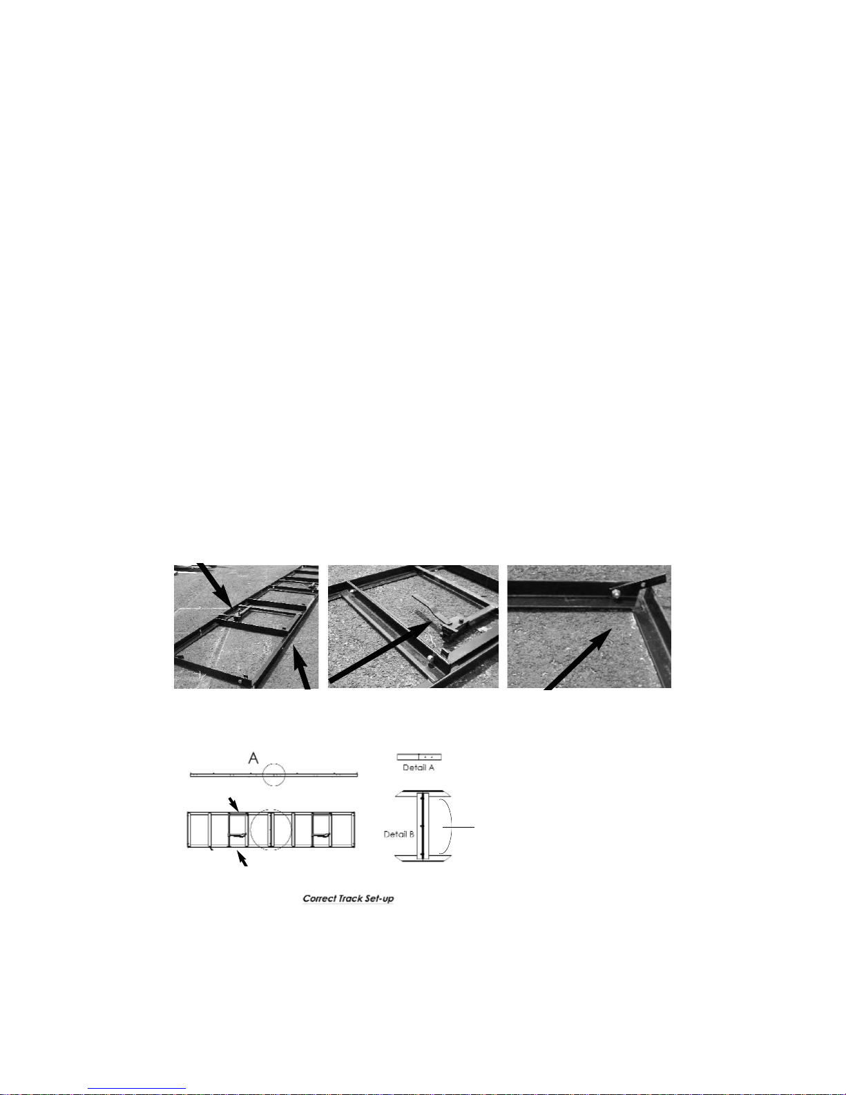
B. Welded Track Assembly
a) Dogs needs to facing in the same direction, the moveable dogs need to be on the
same side of the track which is on the operator's side of the mill head.
b) There are additional holes in the track so that the dogs can be moved to different
positions.
c) The tracks are bolted together using bolt and nuts. The Oscar 18 and 228 mills will
have 2 bolt/nuts: the Oscar 230/236 and 52 mills will have 3 bolts/nuts. Line up the tracks
so that the center holes align. Using the provided bolts put them through the holes and
finger tighten the nuts. Adjust the track height so that the 2 pieces of track meet flush
and level. Work one side then the other, once level has been achieved, check the track to
see if it aligns vertically. If the track is not aligned correctly use a hammer to tap it into
position. Once this is accomplished tighten the bolts securely.
Bolted together Track
Flush & Level
Track on level ground, free of
obstructions
Moveable dogs on one side
Track Stops
Squaring Pin
Operator’s Side
d) The track comes with four
track stop tabs. They consist of
the track stop tab bolt and nut.
Place the tracks stops in the four
end corners of on the inside of
the track. Place them on the
inside of the track secure them
into place with the bolt and nut.
The track stop tabs are placed at
an angle over the track to prevent
any further travel of the mill
head.
Bolts
Set-Up and Operation
Moveable Log Dog
7
Page 8

8
e) To saw a board accurately, the track needs to be straight and flat. To obtain
this, use a string tied tight from end to end or a level. If the track/trailer has a crown or
dip, you will not be able to saw a straight board.
Correct Track
Incorrect
Dipped Track
C. Machine Set-Up (trailer unit) 20' or 24' Torsion Axle Trailers, (230, 236, 56, Farm
Boss, H360))
a) Set-up area should be relatively level and clear of debris. The head will need to roll
down the track so be sure the area is free of obstructions.
b) Lower the trailer jack and raise the jack until the coupler is free of the hitch. Once
this is done remove the unit from the vehicle. Using the "T" handles, loosen the bolts and
lower the front 2 legs.
c) Do the same to lower back 2 legs, and level the trailer.
d) Lower the center 2 legs last, the track should already be level.
e) On the 121/328 models, you will need to unbolt the head from the track. The travel bolts are located behind your guide arms at the base of the mill head.
f) Once the head is unbolted from travel position, roll it down the track to be sure it is
level. If your head rolls on its own you will need to adjust your leveling legs. Return the
head to the center of the trailer and re-bolt or raise the center legs to lock head into place.
Once the head is secure you can reset the leveling legs.
**Always secure the head before re-leveling the trailer***
g) Once the trailer is level, the head should not roll on its own. If your trailer is not level,
it will not saw your boards correctly. Refer to previous instructions for proper set-up.
Correct
trailer set
up. All legs
are level;
head should
not move on
its own.
D. Setting Head on Track (If Applicable) Ground Models
Once your track is level, you are ready to set the head on the track. Once again, be
sure the area is still free and clear of obstructions. You will want the head to roll
freely down the track.
a) Install the head with operator's side on the same side as the moveable dog. The
discharge side is the side with the squaring pins.
b) Raise the head 3 inches and roll from one end to the other. The head should roll
Legs are
locked into
place,
head will
not move.
Page 9

9
smoothly along the track. If the head "thumps" when it passes over the track joint, check
to make sure the tracks are level. Re-level the track and try rolling the head again. Also
be sure to watch the track as you roll the head, if the track moves, you will need to support the track in that area.
c) Set the guide bracket so that the back bearing is on the same plane as the blade, so
that if the blade were to wander back it would hit the back bearing evenly across the middle of the roller. If the bearing needs to be adjusted up or down, loosen the bolt that holds
it to the guide bracket and space it in either direction using the washers that are on either
side of the bearing.
d) Once the bearing is set, position the guide bracket so that the bearing is spaced 1/8"
behind the back of the blade. Once the bearing is in position, tighten the bolt on the top
of the guide bracket into place. Be sure guide is 90
o
to the blade.
e) The guide shoes are to be set using a sheet of paper to gauge the spacing. Place the
paper between the shoe and the blade, slide the shoe so that it is pinching the paper, and
tighten the bolt so that the shoe is set in place. Do the same on the bottom of the blade.
Note that you do not want the shoes to be pinching the blade so hard that they are prohibiting blade travel.
f) Make sure that all nuts and bolts are tightened firmly.
ALWAYS WEAR GLOVES AND EYE PROTECTION
WHEN OPERA
TING SA
WMILL
Squaring arm on right, adjustable dog on left.
Correct head placement; Operators side is on side
with the scale stick.
Pictured is a close-up of the guide
It shows all the bolts and bearings that
can possibly be adjusted. Note how the
teeth are outside of the guide.
Set-Up and Operation
E. Tensioning the Blade on all Models
NEVER tension your blade with the engine running. Your mill is shipped to you without any tension on the blade. If there is tension left on the blade for a period of time,
it can cause flat spots in the belt.
Page 10

10
This will cause the blade to fall off the wheel. Always remember to de-tension your
blade when you are done sawing for the day.
a) a) To tension or loosen the blade, see figure below.
b) Turn the adjusting bolt or stud, clockwise until 30-35 pounds of torque is achieved.
The recommended tool for this is a torque wrench. By hand, rotate blade 3-4 full revolutions; this centers the blade on the wheels.
c) With gloves on, pull up on the blade at the center guard. Allow for no more than a
¼" movement up or down on the blade.
d) Blade guides must not be so tight they cause the blade to heat up. If this occurs readjust guides.
e) Perform a simple test call the "Flutter" test. Put the guards on and then run the
engine at full RPM's (be sure the blade is not in a cut during this test) and watch the blade
under the blade guard. The blade must run straight, if it does not, shut the engine down
and apply more tension. Keep in mind that over tensioning will also cause the blade to
flutter. You should have attained proper tension around 30-35 pounds.
f) A tensioned blade should come off the bottom of the band wheel and run straight
across to the other band wheel, so there is NO sag in the blade between the two wheels.
Tension nut for
smaller units
(121/328)
F Setting Logs
Once the track is set, the head is in place and the blade is tensioned correctly, you are
almost ready to cut.
a) Place the log determined by the mills size, on the center of the track. Using the log
dogs secure the log to the track. Be sure to dog the log high enough (1/2" way up the log)
to ensure the log does not move. If the log is too big for the log dog to hold in place, but
your sawmill head still rolls unobstructed use the "Cheater" to hold it. (For use on the
121/328 only).
Cheater
Squaring Arm and Adjustable Dog
Page 11

11
G. Getting Ready to Cut
Now is the time to debark or clean your log. This can be achieved by the simple chainsaw attachment, called a Log Debarker (available through Hud-Son Forest Equipment
Inc.) or you can pressure wash or use whatever method available to remove any mud
or bark from the logs. By debarking and cleaning your log it will extend the life of your
blade.
a) Adjust the Hud-Son guides so that they are slightly (no more than 2 inches) wider than
the maximum width of the log.
(Note: as you cut slabs, boards or squares you may need to adjust the guide to ensure
the best performance and quality cuts)
b) Find the top of the log with the blade. Remember, that you may have cheaters in
place so be sure these are clear when making the first cut. You will be removing the top
potion of the log. (top slab)
c) On the manual lift models, crank your head down to the desired height and click up
one notch to set the head. Make sure your blade will clear your dog assembly.
d) Start your engine, let it idle for at least 5 minutes. (Refer to the engine manual for
proper engine maintenance)
e) With the engine in idle position, increase the throttle to start the blade. Sawing
should always be done with the engine in full throttle.
f) Gently push the saw head through the log, pushing on the head frame. If the engine
starts to labor, you are going to fast, slow down. Go slow through burls and knots as the
engine may bog down through these parts of a log.
g) When you are at the end of the log, power down the engine, crank the head up so
that will clear the log and roll back to the front of the log. For ease of operation, put the
slabs on the operator's side of the mill, this way you will not have to dig through sawdust
for your lumber.
h) You now have a flat surface on top of your log, remove the cheaters (if applicable),
you will no longer need them, as long as the log dogs will hold the log in place.
i) Set your log dog assembly so that they are standing in the track. Turn the cut side
of the log, using a cant hook, ¼ of a turn. The flat side must be flush against the squaring
pin to assure a square cant.
j) Adjust the log dog at an angle to the track so that the blade can pass over the top,
but so that the dogs are effective in securing the log.
Debark the log.
Guide location
- log width
Page 12

k) Once again, increase the engine throttle to start the blade, and saw another slab.
You will repeat step (I) until your log is squared into a cant. You may now saw your
dimensional lumber.
l) Steps (I-K) may not be applicable if a cant is not desired.
Adjustable dog, set at an angle so that log can be
sawed without interference.
Place flat side, flush against squaring pin to
ensure a square cant.
H. Cutting Dimensional Lumber
You can cut down to a 1" thick bottom board. To achieve this you will use the moveable side of the dog and the short squaring pins welded in the track.
a) You will need to determine the size lumber that can be cut and how many, then using
the scale start sawing your lumber. Lower the blade to desired thickness and saw your
board. Repeat this process unit all lumber is cut.
b) You may need to turn your cant to make the desired lumber.
I. Replacing the Blade
No matter how well you care for your blade, they will dull after time and need to be
changed. Longevity of your blade depends on how well you maintain it.
a) The engine needs to be stopped, turned off and the key removed, this ensures that
the engine can not be accidentally turned back on. On engines with manual start, you will
need to remove the spark plug wire prior to servicing. On electric motors a lockout/tagout
should be used.
b) Loosen and remove wing nuts so you can remove the outside and center guards on
all models.
c) Loosen band blade tensioner bolt until adjusting bolt is flush with threaded plate.
d) With a gloved hand, put hand on the top of the band blade and push down. (Use
extreme CAUTION, dull blades are still sharp and may be hot).
e) Remove band blade from both band wheels and take out of carriage.
f) Inspect new or sharpened blade, be sure blade teeth are facing in correct direction.
Teeth should always point away from the operator. (Towards discharge chute). Be sure
to wipe blade clean of all oily substance prior to installing. Aclean, dry rag or cloth works
best.
g) Starting from your stationary wheel set the blade on the wheel then thread though
your guides. Work the blade over the tensioning wheel until the blade is set.
h) Lightly tension the blade to remove the slack, and then turn the wheel in the direction of travel (towards the operator) 3-4 rotations to be sure the blade is tracking properly on the wheel.
12
Page 13

13
i) Once the new blade is tracking properly, replace the guards and re-tension the blade
as previously stated.
J. End of Processing Lumber
a) Completely decrease engine throttle and turn engine switch, red one, to off position.
b) The blade will continue to turn automatically and will coast to a stop.
c) If you are done sawing for the day, de-tension the blade, so that you do not have flat
spots. Lower the mill head so that the lift cable has slack.
K. Blade Maintenance
Longevity of band blades depends on how well they are cared for. Using a lube tank,
Log Debarker, band blade sharpener, tooth setter, all will help keep your blade in top
condition. Be sure to clean your logs by using a pressure washer or debarker to keep
them free of mud and debris. Refer to 2A on page 6
L. Blade suggestions
a) Never force a dull blade, this will result in overheating of the blade and result in
wavy lumber.
b) Overuse of a blade jeopardizes the ability of the saw blade to be re-sharpened.
c) A new blade may stretch after cutting and may have to be re-tensioned to assure
quality lumber.
d) De-tension the band blade after each day of cutting.
e) Never operate the mill without the guards in place.
The Hud-Son Forest Equipment, Inc sawmill comes with a band blade and we have an
excellent re-sharpening program for your band blade.
M. Adjusting Sawmill Guides
a) Purpose of the Guides
• Superior Hud-Son guide design. Supports on the top, bottom and back of the
blade, where can the blade go? This guide design limits the chance of blade wander.
• The lower blade holds the blade up and decreases the chance of "diving". Most
companies only use a top support.
• The closer to the log the guides are to the log the better support the blade has
as it cuts.
b) Adjusting the guides
• Tools that will be needed:
1) 17 mm wrench
2) 17 mm socket
3) 9/16" wrench
4) 3/16" Allen wrench
Page 14

14
• All guides are aligned and set at the factory, but occasionally they get moved
out of adjustment in shipping or after a period of usage. It is important that they be
checked often for proper alignment and adjusted correctly.
• To adjust your guides correctly you must first tension the blade properly as previously described. A tensioned blade should come off the bottom of the band wheel and
run straight across to the other, so there is NO sag between the two wheels.
c) Now that the blade is tight, slightly loosen the Allen head that holds the guide shoes,
so that they slide up and down freely. Now loosen the bolt that fastens the aluminum
guide bracket to the guide rod, so that the guide bracket can be moved in, out and it can
be rotated in either direction.
d) Set the guide bracket so that the back bearing is on the same plane as the blade, so
that if the blade were to wander back it would hit the back bearing evenly across the middle of the roller. If the bearing needs to be adjusted up or down, loosen the bolt that holds
it to the guide bracket and space it in either direction using the washers that are on either
side of the bearings.
e) Once the bearing is set, position the guide bracket so that the bearing is 1/8" behind
the back of the blade. Once the bearing is in position, tighten the bolt on top of the guide
bracket in to place. Be sure the guide is 90 to the blade.
f.) The guide shoes are to be set using a sheet of paper to gauge the spacing. Place the
paper between the shoe and the blade, slide the shoe so that it is pitching the paper and
tighten the bolt so that the shoe is set in place. Do the same on the bottom of the blade.
Note that you do not want the shoe to be pitching the blade so hard that it is prohibiting
blade travel
g) Make sure that all nuts and bolts are tightened firmly.
N. Using the Lumber Scale
a) All Hud-Son sawmills are equipped with a Lumber Scale. The scale is used to make
the dimensioning process simple. The scale incorporates 4 separate scales with the blade
kerf factored in for each increment.
Scale Resulting Thickness
4/4 1”
5/4 1 - 1/4”
6/4 1 - 1/2”
8/4 2”
Note:
The 1" standard ruler does NOT account for kerf. When using this scale be sure to
plan on kerf. 1" increments will result in approximately a 7/8" end result, depending
on what blade is being used.
Page 15

15
Actual Blade Height
Used For Scaling
Inch Scale
8/4 Scale Row = 2”
Lumber
6/4 Scale Row =
1 - 1/2” Lumber
5/4 Scale Row =
1 - 1/4” Lumber
4/4 Scale Row
= 1” Lumber
Care and Maintenance
Hud-Son Saw Mills require a certain amount of care and maintenance, so that it may
continue to perform at its best. If you are not confident in your ability to perform the
maintenance that is required, please look into having a professional come in and perform the work for you.
Page 16

16
Cleaning your Saw Mill
Using an air hose, blow off all loose debris that builds around the unit.
Use extreme caution when cleaning the mechanism.
Never use flammable or combustible materials to clean the mill.
Be in a well ventilated area. Always wear protective equipment to
prevent injury.
Use proper procedure to dispose of waste materials.
Wipe down the idler and pulley wheels using an air hose, brush or rag.
Clean and inspect blade guides.
Preventative Maintenance
For electrical engine follow the correct Lockout/Tagout procedures.
Check for correct blade tension guaranteeing that 30-35 pounds of torque is
on tensioning bolt/nut.
Check blade tracking, a 1 - ¼" blade should be centered on band wheels.
Check bearing, idler and pulley wheels for wear. Sighs of wear are:
Excessive heat
Squeaking sounds
Looseness
Grease idler, pulley wheels and bearings.
Grease blade tensioner shaft.
Grease the lift tubes.
Check all belts for wear and to make sure the belt tension is "taut".
Belt should have no more than ½" deflection.
Looseness
Grease idler, pulley wheels and bearings.
Grease blade tensioner shaft.
Grease the lift tubes.
Check all belts for wear and to make sure the belt tension is "taut".
Belt should have no more than ½" deflection.
Page 17

17
MAINTENANCE SCHEDULE CHART
Service Recommendations for Hud-Son Sawmills
Service Item
Daily
40
Hours
See
Manual
Check Engine Oil Level
Check/Clean Engine Air Filter
Check Hydraulic Oil Level (fill 1” from top) if applicable
Clean Unit of Bark, Saw Dust, and other Debris
Lubricate Grease Fittings and Oil Points (see Diagram for locations)
Check Tire Pressure - Upon transport (if applicable)
Check Cylinders and Seals for Leakage
Check Feed Chains for tension (if applicable)
Clean Battery Connections
Check Wiring and Connections for Corrosion and Decay
Lubricate Chains (if applicable)
Check Blade Sharpness
Fuel - fill as needed
Blade Lubricant - fill as needed -
Refer to 2A on page 6
Check hoses/gauges for damage, cracks, leakage (chaffing, dry rot, cracks,
replace hoses if applicable)
* Change engine oil after 8
hours of operation on a new
engine (break -in period)
CAUTION!
Maintenance Procedures requiring special training or
tools should be performed by a trained technician.
A routine inspection of the entire machine is encouraged. Check to see if all fittings are
tight and secure. Make sure all nut are tightened. Check to see any damage that may need
to be repaired before and further damage occurs. Routinely checking the equipment and
proper maintenance will help in keeping the Hud-Son Saw Mill running to the best of its
ability.
Page 18

Parts and Warranty
Mill Replacement Parts
Out sourced components will be warranted by the respective company for a period equal
to the warranty in place at the time of shipping, as shown below from date of purchase.
Description
Part Number
Warranty
Gasoline Engine
6.5 HP, 8.0 HP, 16 HP,
18 HP, 21 HP, 23 HP, 31 HP
Up to 2 Years
See Briggs & Stratton
Manual
Electric Engine
131549
1 Year - call Hud-Son
and ask for warranty
department.
1.5” Pillow Block
Bearing, 1” Pillow
Block Bearing
UCP 208-24
UCP 205-16
6 Years
Drive Belt
Oscar 121/328 - B77,
Oscar 230/236/FB/H360 - B85,
52, B92
1 Year - Call
your servicing
Hud-Son Dealer.
Rubber Wheel Belting
16” Wheel B49,
19” Wheel - B56.5
1 Year Defect
Urethane Wheel Belting
16” Wheel HF 49, 19” Wheel - HF
56.5 - 25” Wheel - HF 77
1 Year Defect
Not Melted
1 Year Defect
Sk 1 - 1/2
1 Year
Drive Belt Tensioner
(Idler Pulley)
Oscar121/328 - Idler Pulley
1 Year
Guide Assembly,
Left/Right (see break-
down for parts list)
976-001
30 Days
Call
your servicing
Hud-Son Dealer.
Scale Sticker
24” Scale Sticker
Scale decal
36” & 48” Scale Sticker -
Scale Decal 36 & 48
1 Year
Site Glass Assembly
DH-1006 1 Year
Cable Lift Kit Assembly
Oscar 121/328, Oscar 230/236,
Oscar 52,
Farm Boss/H360
1 Year
Band Blade
Oscar 121/328 - WM 132, (132”x.035x11/4”)Oscar 230 - WM 160, (160”x.035x1-1/4”)
Oscar 236/FB/H360 - WM 167, (167”x.042x1-
1/4”)Farm Boss w/25” band wheels - WM 189,
(189”x.042x1-1/4”) - Oscar 52 - WM 221,
(221”x.0542x1-1/2”)
Breakage &
Re-sharpening -
Call Wood-Mizer, Inc.
at 1-800-244-4600
18
Page 19

19
Part Picture
Description
Part Number
Warranty
Winch
Oscar 121/328/230
DBL800A - (hand crank)
Oscar 236/52/FB/H360 -
ATV2500 - (you will need your
serial # for warranty)
1 Year - call your servicing
Hud-Son Dealer.
Winch Switch
C7755- 236/FB
H2HG/H360
Oscar 52
1 Year - call your servicing
Hud-Son Dealer.
Winch Solenoid
C7700 - 236/FB
H2HG/H360
Oscar 52
1 Year - call your servicing
Hud-Son Dealer.
Clutch
4075P007 - Oscar 121/328
Oscar 230/236/FB/H360 160021- Oscar 52 180021
(double pulley)
30 Days- Call your servicing
Hud-Son Dealer.
Band Wheel
16” - 1B160DSK
19” - 1B184SK
25” - 1B250SK
1 Year - call your servicing
Hud-Son Dealer.
Log Dog Only
Log Dog (121/328)-976-027
Dog Only (230/236)-976-028
2 Years - call your servicing
Hud-Son Dealer.
Track Wheel
w/Replacement Bearing
976-019 - Trolly
2 Years - call your servicing
Hud-Son Dealer.
Replacement Bearing for
Track Wheel
6203-2RS
2 Years - call your servicing
Hud-Son Dealer
Pulley for Lift Cable 976-004 - Cable - Pulley
1 Year - call your servicing
Hud-Son Dealer.
Lift Cable Cable
Cheater
O18-003 - Oscar 121 -
Cheater
O228 - 003 - Oscar 328 -
Cheater
2 Years - call your servicing
Hud-Son Dealer.
Guide Pins
DH-1098 - Oscar121/328
Oscar 230/236/FB/H360
Oscar 52
2 Years - call your servicing
Hud-Son Dealer.
Low Handle Kit Oscar 230/236 - DH 7009
2 Years - call your servicing
Hud-Son Dealer.
Page 20

20
Bolt for Track Wheel 976-026 - Trolly-Bolt
2 Years - call your
servicing Hud-Son Dealer.
Track Sections
1 Year - call your servicing
Hud-Son Dealer.
Axles (Trailer Models)
1 Year - call your servicing
Hud-Son Dealer.
Hydraulic Motors, Pumps,
Valves, Hose & Fittings
1 Year - call your servicing
Hud-Son Dealer.
Sprockets & Chain
90 Days - Call Hud-Son
and ask for the warranty
department
Parts and Warranty
Parts and Warranty
Warranty:
Warranty registration cards must be completed and returned to Hud-Son Forest
Equipment, Inc. within 30 days of purchase. Failure to do will void the warranty!!
Warranty claims must be registered with the Dealer/Distributor, and defective parts must
be returned to the Dealer/Distributor at the owner's expense. The Dealer/Distributor will
assume cost of the shipping one way in regards to any warranty claim. Freight is standard
UPS ground. Any expedited services are at an additional charge and will be paid in full
before shipping at the owner's expense. The shipping of warranty/parts out of the continental USA, will not be covered under warranty. The labor charge out of the continental
USA is also not covered under warranty.
All mills have a 2 year warranty against manufactures defects.
Excluding the H360, and Oscar 52, they have a 1 year warranty.
Warranty Claim Procedure
All warranty claims that are done in the field will be handled as follows:
1 - Customer will call the Dealer/Distributor and acknowledge the problem.
2 - If the problem can be solved in the field, new parts will be shipped, invoiced and paid
for. A credit will be given once the old parts are returned, if covered by warranty.
3 - If requested, parts to be replaced must be returned, at owner's expense within 30-days
to receive credit.
4 - If the problem is deemed to severe to be fixed in the field by the customer, then the
customer must bring the saw mill, at the owner's expense, to the closest Hud-Son
Dealer/Distributor for repair. If the Dealer/Distributor is not qualified to make the
repairs, then the equipment must be returned to Hud-Son Forest Equipment, Inc at the customer's expense.
5 - If the problem is deemed not to be a warranty problem, an invoice will follow for the
Page 21

21
parts that were replaced, as well as an invoice for any time spent on the mill by Hud-Son
Forest Equipment, Inc staff and/or Dealer/Distributor staff.
6 - Any modification to the band mill that is performed by any personnel other than HudSon Forest Equipment, Inc direct staff voids the warranty.
7 - Any parts that are replaced without the discretion of the Dealer/Distributor voids the
warranty on the part the customer is replacing and no reimbursement will be made.
8 - Parts purchased by the customer from an outside source, without prior approval from
Hud-Son Forest Equipment, Inc will NOT be reimbursed.
ALWAYS CALLYOUR SERVICING DEALER FIRST!!
Dealers/Distributors carry parts and are very knowledgeable with the inner workings of
your sawmill. Remember that modifying your mill or using parts that are Not Hud-Son
Forest Equipment Inc approved, can void your warranty.
CE Approved Models: European Mills
Warranty on Parts ONLY!! No warranty on labor or shipping.
Warranty/Service Information:
Please contact our warranty department with any issues or to reorder parts,
at 315-896-4316 or 1-800-765-7297. Hours of operation are M-F 8:00 - 4:30 est.
IF NOT IN THE CONTINENTAL USA - HUD-SON DOES NOT PAY
FREIGHT OR SHIPPING ON WARRANTY OR LABOR.
Follow all the steps to safely transport the Hud-Son Saw Mill Trailer Model
1 - Lock head into travel position.
2 - Raise extension legs and lock in upright positions.
3 - Raise rear legs of frame and pin in raised position.
4 - Raise jack to desired height, remove pin and rotate to horizontal position, hook hitch
to vehicle. Plug in lights and brakes. Hook-up safety chains and break-away switch. (If
applicable)
5 - Lift front legs and lock in transport position.
6 - Be sure to clean unit of all loose debris, including all bark, sawdust and dirt.
Transport Instructions
Page 22

Trouble Shooting
Problem Cause Solution
Blade is Diving/Rising
Dull Blade
RPM’s Not High Enough
Blade Not Tensioned Properly
Sawing Soft Pitch Wood
(Pitch Build-Up in Blade Gullets)
Sharpen or Replace Blade
Saw at Full Throttle
Check Torque on Tensioning Bolt
(Perform “Flutter” Test)
Use Lubricant on Blade
PETROLEUM PRODUCTS, MINERALOIL
OR VEGETABLE OILSHOULD NOT BE
USED ON OUR MILLS
Saw Tree from the Top to the Bottom
(small end to wide end)
Slow Down Reset Teeth to Proper Set
Mill Sawing Hard
RPM’s Not High Enough on Engine
Belt is Slipping
Sawing Hardwood
Dull Blade
Bark or Sawdust Build-up on Wheels or
Track
Always Saw at Full Throttle
Adjust Belt Tension
Slow Down your Sawing Speed
Sharpen or Replace Blade
Clean Wheels and Track
Clutch Slipping Debris and/or Oil can cause slippage
Clean out clutch bell
Inspect/repair springs and shoes
Engine Powers Down
(Loosing RPM’s)
Pushing the Mill too Fast
Dirty Air Filter
Dull Blade
Slow Down your Sawing Speed
Clean/Change
Sharpen/Replace Blade
Mill not Sawing Square
Over Dogged
Track Not Level & Square
Cables are Out of Line
Guides are Out of Adjustment
Not Putting Flatside of Cant Flush with
Squaring Post on the First Turn
Bad Trolley Bearing
Loosen Dog Pressure
Level Track
Re-adjust Cables
Re-Adjust Blade Guides
Put Cant on Flatside, Flush with
Squaring Post
Replace Trolley Wheel
Log Moves When Dogged
Over Dogged, too Much Pressure on
Dogs
Loosen Dog Pressure
New Blade Will Not Cut Blade Could Be Turned Inside Out
Turn the Blade So That the Teeth are
Pointing to the Discharge Direction
Boards have Fine or Large
Lines in them Every Several
Inches in a Repeating Pattern
A Tooth in the Blade is Out of Set Reset Tooth in Blade
22
Page 23

Oscar 121 Mill Assembly
34
1
16
3
17
2
31
35
19
24
7
9
11
12
46
45
21
13
18
41
10
48
22
14
23
8
42
32
6
29
5
10
15
20
22
14
10
26
22
37
4
36
24
43
14
47
25
1
44
39
38
27
40
13
28
33
ITEMS NOT SHOW ON MODEL
Part No
Description
Qty
1
1
4
1
45504
45504
45112
07-302
5/32” Lift cable - 56”
5/32” Lift Cable - 86”
Cable Clamps
1/4” Fuel Line 56”
Decals
23
30
Page 24

24
Item No. Part No. Description Qty
1 10542-02299
KEYWAY
1/4" X 1/4" X 2"
3
2 17155 HCS 7/16 - 20 X 1 Z5 1
3 1133624 SPLIT L/W 5/16" Z 1
4 110120300 HCS 1/4 - 20 x 1/2 Z5 1
5 11343-00644 NY 1/2 X 1 1/4 X .062 7
6 12057 HCS 3/8 - 16 X 1 P5 5
7 13060 HCS 1/4 - 20 X 1 Z5 4
8 13112 HCS 3/8 - 16 X 2.25 Z5 1
9 33006 USS F/W 5/16 Z 14
10 33086 SAE F/W 1/2" Z 17
11 33620 L/W 5/16 Z 7
12 36303 FHN 5/16" - 18 P5 7
13 36305 FHN 3/8 - 16 P5 7
14 36310 FHN 1/2" - 13 Z5 11
15 37341 FLNG LK 3/8 - 16 Z 3
16 4075P007
CLUTCH PULLEY .75
1AB 2.50
1
17 410-803 HRUSH WASHER 1
18 75051
2.5 GALLON LUBE
TANK
1
19 1132037
HWH 10 X 3/4"
TEKS3 - SELF-TAP
1
20 1133012 USS 1/2 F/W Z 6
21 1133082 SAE 3/8 F/W Z 4
22 1133626 1/2" SPLIT L/W Z 10
23 1137024 NYLOCK 3/8 - 16 Z 1
24 110120344 HCS 3/8 - 16 X 1 Z5 5
Oscar 121 Mill Parts List
Oscar 121
Page 25

25
25 110120384 HCS 1/2 - 13 X 2 1/2 Z5 4
26 110120390 HCS 1/2 - 13 X 4 Z5 4
27 976-001-L GUIDE ASSEMBL Y 1
28 976-001-R GUIDE ASSEMBLY 1
29 976-004
CABLE PULLEY -
00158
4
30 976-006 EYE BOLT - L3 2
31 976-009
SHOULDER BOLT FOR
00158 PULLEY
1
32 976-010
SHOULDER BOLT - 3/8
X 2.5
2
33 B-77 V-BELT 1
34 BS-8 10HP ENGINE 1
35 DH-1006
SITE GLASS
ASSEMBLY
1
36 DH-1007 LUBE HOSE BRACKET 1
37 DH-1078
SHEAVE ASSEMBLY
W/BELTING
1
38 DH-1098 GUIDE PIN ASSEMBLY 2
39 DH-1099 SHEAVE W/RED PAINT 1
40 DH-2523
18/228 CENTER GUARD
"HUD-SON"
1
41 F1406 TANK STRAP 1
42 FA3002SB0002
3" FLAT BELT IDLER
W/BUSHING
1
43 O18,O228--004-01 GUIDE SLIDE BAR 1
44 O18,O228-004-04
PILLOW BLOCK KEY
SHAFT
2
45 O18,O228-006
18/228 GUARD
ASSEMBLY
2
46 O18-001 OSCAR 121 CAGE ASSEMBLY 1
47 O18-002
OSCAR 121 HEAD
ASSEMBLY
1
48 UCP208-24-Q PILLOW BLOCK 4
49 WM132
132" BAND BLADE:
18/228
1
Page 26

26
Oscar 121 Cage Assembly
Oscar 121 Cage Parts List
O18-001
Item No. Part No. Description Qty.
1 33078 SAE F/W 1/4 Z 2
2 1133006 F/W USS 5/16 Z 6
3 1133620 SPLIT 5/16 L/W Z 3
4 1136304 FHN 5/16 - 18 Z5 3
5 1136306 3/8 - 16 FHN Z5 4
6 1136316 3/4 - 10 FHN Z5 4
7 110120325 HCS 5/16 - 18 X 1 14 Z5 3
8 976-013 WINCH 1
9 DH-1064 MILLS - WINCH PLATE ASSEMBLY 1
10 DH-1065 PULLEY BRACKET ASSEMBLY 1
11 DH-1071 TRACK WHEEL ASSEMBLY 4
12 O18-001-00-1 OSCAR 121 CAGE WELDMENT 1
13 O18-001-04 OSCAR 18 LIFT TUBE 2
14 O18.O228-003-01 GUSSETT - 1 3/4" X 1/4" FLAT 1
15 SS-0012 1 1/2" Angle Bracket w/Hole 12
16 SS-0013 1 1/2" BRACKET NO HOLE 4
7
3
2
4
13
1
6
12
11
5
16
15
9
14
10
8
Page 27

27
Part No. D/13
Ruler 24” Scale Inch
ruler not shown
Head Assembly
Oscar 121
O18-002
Item No. Part No. Description Qty.
1 12105 HCS 3/8 - 16 X 1 P5 2
2 33086 SAE F/W 1/2" Z 1
3 36305 FHN 3/8 - 16 P5 2
4 36410 FHN 1/2" - 13 YZ8 1
5 11343-00204 TAP BOLT- GR 1/2 X 5 1
6 60108 Curt ZERK 3/16" - GREASE FITTING 2
7 DH-2223 TENSION PLATE 1
8 DH-2223 TENSION BLOCK PLATE 1
9 O18,O228-002-00-2 SLIDE TUBE ASSEMBLY 2
10 O18,O228-002-00-4 BELTADJUSTER BRACKET ASSY 1
11 O18,O228-002-00-5 GUARD BRACKETASSEMBLY 2
12 O18,O228-002-00-7 SLIDE TUBE ASSY 1
13 O18,O228-002-00-8 LONG GUIDE POCKET 1
14 O18,O228-005-00-1 LUBE TANK BRACKET 1
15 O18-002-00-1 O121 HEAD SUB-ASSY 1
16 O18-002-00-3 SCALE STICK 1
17 O228-005 MOTOR BRACKET ASSEMBLY 1
18 SS-0012 1 1/2" Angle Bracket w/Hole 2
19 SS-0014 3" X 1 1/2" ANGLE BRACKET W/HOLE 2
Head Parts List Oscar 121
17
16
12
14
13
3
18
6
8
2
5
15
4
7
10
11
19
1
Page 28

28
Track Assembly
Oscar 121
7
8
3
10
4
6
2
5
9
O18-005
Track Parts List Oscar 121
Item No. Part Number Description Qty.
1
1136302
FHN 1/2 - 20 Z5 2
2
1136310
FHN 1/2 - 13 Z5 6
3 110120304 HCS 1/4 - 20 X 1 Z5
2
4 110120380 HCS 1/2 - 13 X 1 1/2 Z5 6
5 976-027 SMALL LOG DOG 2
6 DH-0939 TRACK STOP BRACKET 4
7 DOUBLE HEADED NAIL DOUBLE HEADED NAIL - 2 1/2” 4
8 O18-003 LOG SUPPORT 2
9 O18-005-00-1W OSCAR 121 TRACK WELDMENT 2
10 O18-005-00-2 OSCAR 121 J-BAR WELDMENT 2
Page 29

29
Trailer Assembly
Oscar 121
Item No. Part No. Description Qty
1 0091060 COUPLER 1
2 1133012 USS 1/2 F/W Z 2
3 1136310 FHN 1/2 - 13 Z5 2
4 110120384 HCS 1/2 - 13 X 2 1/2 Z5 2
5 3S140 TRAILER TIRE 2
6 4-150-02-00 4 1/2” HUB 2
7 O18-005 OSCAR 121 TRACK ASSEMBLY 1
8 O18-006-00-1 OSCAR 121 TRAILER FRAME WELDMENT 1
O18-006
Trailer Parts List Oscar 121
3
2
4
6
5
8
1
7
Page 30

30
Oscar 328 Mill Assembly
31
7
18
20
1
13
14
3
2
32
29
5
27
12
42
10
34
24
45
11
41
9
19
40
4
33
8
39
21
28
11
17
44
38
24
15
41
19
26
25
37
30
46
10
Items Not Shown in Model
Part No Description Qty.
45504 5/32" Lift Cable - 56" 1
45504 5/32" Lift Cable - 86" 1
45112 Cable Clamps 4
07-302 1/4” Fuel Line 56” 1
DECALS
Page 31

31
Item No. Part No. Description Qty.
1 10542-02299 KEYWAY1/4" X 1/4" X 2" 1
2 17155 HCS 7/16 - 20 X 1 Z5 1
3 1133624 SPLIT L/W 5/16" Z 1
4 110120300 HCS 1/4 - 20 x 1/2 Z5 1
5 11343-00644 NY 1/2 X 1 1/4 X .062 6
6 12057 HCS 3/8 - 16 X 1 P5 2
7 13060 HCS 1/4 - 20 X 1 Z5 4
8 13112 HCS 3/8 - 16 X 2.25 Z5 1
9 33086 SAE F/W 1/2" Z 19
10 36305 FHN 3/8 - 16 P5 7
11 36310 FHN 1/2" - 13 Z5 12
12 37341 FLNG LK 3/8 - 16 Z 3
13 4075P007
CLUTCH PULLEY .75 1AB
2.50
1
14 410-803 THRUSH WASHER 1
15 75051 2.5 GALLON LUBE TANK 1
16 1132037
HWH 10 X 3/4" TEKS3 -
SELF-TAP
1
17 1133012 USS 1/2 F/W Z 6
18 1133620 SPLIT 5/16 L/W Z 4
19 1133626 1/2" SPLIT L/W Z 8
20 1136304 FHN 5/16 - 18 Z5 4
21 1137024 NYLOCK 3/8 - 16 Z 1
22 110120344 HCS 3/8 - 16 X 1 Z5 1
23 110120384 HCS 1/2 - 13 X 2 1/2 Z5 4
OSCAR 328
Trailer Parts List Oscar 328
Page 32

32
Item No. Part No. Description Qty.
24 110120384 HCS 1/2 - 13 X 4 Z5 4
25 976-001-L GUIDE ASSEMBL Y 1
26 976-001-R GUIDE ASSEMBLY 1
27 976-004
CABLE PULLEY -
00158
3
28 976-006 EYE BOLT - L3 2
29 976-010
SHOULDER BOLT
- 3/8 X 2.5
3
30 B-77 V-BELT 1
31 BS-8 10HP ENGINE 1
32 DH-1006
SITE GLASS ASSEM-
BLY
1
33 DH-1007 LUBE HOSE BRACKET 1
34 DH-1078
SHEAVE ASSEMBLY
W/BELTING
1
35 DH-1098 GUIDE PIN ASSEMBLY 2
36 DH-1099 SHEAVE W/RED PAINT 1
37 DH-2523
18/228 CENTER GUARD
"HUD-SON"
1
38 F1406 TANK STRAP 1
39 FA3002SB0002
3" FLAT BELT IDLER
W/BUSHING
1
40 O18,O228--004-01 GUIDE SLIDE BAR 1
41 O18,O228-004-04
PILLOW BLOCK KEY
SHAFT
2
42 O18,O228-006
18/228 GUARD ASSEM-
BLY
2
43 O228-001 328 CAGE ASSEMBLY 1
44 O228-002 O328 HEAD ASSEMBLY 1
45 UCP208-24-Q PILLOW BLOCK 4
46 WM132
132" BAND BLADE:
18/228
1
Page 33

33
Oscar 328 Cage
Assembly
Cage Parts List
Oscar 328
Item No Part No Description Qty
1 1133006 F/W USS 5/16 Z 6
2 1133620 SPLIT 5/16 L/W Z 3
3 1136304 FHN 5/16 - 18 Z5 3
4 1136306 3/8 - 16 FHN Z5 4
5 1136316 3/4 - 10 FHN Z5 4
6 110120325 HCS 5/16 - 18 X 1 14 Z5 3
7 110120344 HCS 3/8 - 16 X 1 Z5 2
8 976-013 WINCH 1
9 DH-1064 MILLS - WINCH PLATE ASSEMBLY 1
10 DH-1065 PULLEY BRACKET ASSEMBLY 1
11 DH-1071 TRACK WHEEL ASSEMBLY 4
12 O18.O228-003-01 GUSSETT - 1 3/4" X 1/4" FLAT 1
13 O228-001-00-1 OSCAR 328 FRAME WELDMENT 1
14 O228-001-04 LIFT TUBE STOP 2
15 O228-001-05 LIFT TUBE 2
16 SS-0012 1 1/2" Angle Bracket w/Hole 10
17 SS-0013 1 1/2" BRACKET NO HOLE 2
18 SS-00A1 8 3/8" BRACE 8
O228-001
18
5
13
11
7 4
14
17
16
3
9
8
6
1
2
10
12
15
Page 34

34
Oscar 328 Head
Assembly
Part No. D/13 - Ruler 24”
Scale Inch ruler not shown
Head Parts List Oscar 328
O228-002
Item No Part No Description Qty
1 33086 SAE F/W 1/2" Z 1
2 36305 FHN 3/8 - 16 P5 2
3 144583 TAP BOLT - GR 1/2 - 13 X 4.5" 1
4 1136310 FHN 1/2 - 13 Z5 1
5 110120344 HCS 3/8 - 16 X 1 Z5 2
6 60108 Curt ZERK 3/16" - GREASE FITTING 2
7 DH-2223 TENSION PLATE 1
8 O18,0228-002-00-6 TENSION BLOCK PLATE 1
9 O18,O228-002-00-2 SLIDE TUBE ASSEMBLY 2
10 O18,O228-002-00-4 BELTADJUSTER BRACKET ASSY 1
11 O18,O228-002-00-5 GUARD BRACKET ASSEMBLY 2
12 O18,O228-002-00-7 SLIDE TUBE ASSY 1
13 O18,O228-002-00-8 LONG GUIDE POCKET 1
14 O18,O228-005-00-1 LUBE TANK BRACKET 1
15 O228-002-00-1 O328 HEAD SUB-ASSY 1
16 O228-002-00-5 O228 SCALE STICK ASSEMBLY 1
17 O228-005 MOTOR BRACKET ASSEMBLY 1
18 SS-0012 1 1/2" Angle Bracket w/Hole 2
19 SS-0014 3" X 1 1/2" ANGLE BRACKET W/HOLE 2
13
18
16
17
12
2
8
9
6
19
3
1
4
7
3
11
15
5
14
Page 35

35
Track Assembly Oscar 328
O228-003A
Track Parts List Oscar 328
Item
No.
Part No. Description Qty.
1 1136302 FHN 1/4 - 20 Z5 2
2 1136310 FHN 1/2 - 13 Z5 6
3 110120304 HCS 1/4 - 20 X 1 Z5 2
4 110120380 HCS 1/2 - 13 X 1 1/2 Z5 6
5 976-027 SMALL LOG DOG 2
6 DH-0939 TRACK STOP BRACKET 4
7 O228-003-00-1 O228 TRACK WELDMENT 2
8 O228-003-00-2 J-BAR 2
9 O228-003-00-3 LOG SUPPORT 2
10 Not applicable Nails (Not Shown) 4
2
6
8
1
3
5
9
7
4
Page 36

36
Trailer Assembly Oscar 328
Item No. Part No. Description Qty
1 0091060- Coupler COUPLER 1
2 1133012 USS 1/2 F/W Z 2
3 1136310 FHN 1/2 - 13 Z5 2
4 110120384 HCS 1/2 - 13 X 2 1/2 Z5 2
5 3S140 TRAILER TIRE 2
6 4-150-02-00 4 1/2" HUB 2
7 O228-003 A TRACK ASSEMBLY 1
8 O228-004-00-1
OSCAR 328 TRAILER FRAME
WELDMENT
1
O228-004
Trailer Parts List Oscar 328
7
6
5
8
1
4
2
3
Page 37

37
Item No. Part No. Description Qty.
1 6200-2RS 6200-2RS BEARING 1
2 976-001-SW SMALL WASHER 2
3 976-001-01 GUIDE MAIN BODY 1
4 976-001-02 GUIDE BRACKET 1
5 976-001-03 SHORT GUIDE BRACKET 1
6 976-001-04 O18-001-04 1
7 976-001-06 GUIDE WASHER 5
8 976-001-AB GUIDE - ALAN BOLT 1
9 976-001-B GUIDE BOLT 1
10 976-001-BOLT-1 BOLT 1
11 976-001-LN GUIDE - LOCK WASHER 2
12 976-001-RB GUIDE -LOCK WASHER 1
13 976-001-SCREW GUIDE -SCREW 2
14 976-001-SPW GUIDE - SPLIT WASHER 1
15 CP20-10A O18-0001-05 2
976-001-R
Guide Assembly Parts List
Item
No.
Part No. Description Qty.
1 976-019
TW3 TRACK
WHEEL
1
2 976-026 SHOULDER BOLT 1
3
11343-
00592
F/W 3/4 X 1 X 1/8 Z 2
4 1133092 SAE F/W 3/4" Z 1
5 1168060 C-CLIP 1
6 6203-2RS BEARING - 3/4" ID 1
DH-1071
Track Wheel Assembly Parts List
1
3
2
1
1
4
5
8
1
15
7
2
9
13
4
10
11
3
12
14
Page 38

38
Site Glass Assembly Parts List
Item No. Part No. Description Qty.
1 38655 HCS 10MM - 1.5 X 25 8.8 Z 2
2 90702 M10 - 1.5 FLANGE NUT ZP 2
3 1137406 LK 8 - 2 4
4 SS-0029 SIGHT GLASS BRACKET 1
5 UG-001 SITE GLASS 1
DH-1006
Item No. Part No. Description Qty
1 976-027-1 HANDLE 1
2 976-027-10 GRAB SPACER 1
3 976-027-2 PIVOT ROD 1
4 976-027-3 REAR POCKET 1
5 976-027-4 MAIN SUPPORT 1
6 976-027-5 PLATE 2
7 976-027-6 FRONT POST 1
8 976-027-7 ROCKER PIN 1
9 976-027-8 SPACER 1
10 976-027-9 GRAB 1
976-027
Small Log Dog Parts List
Small Dog
2
3
4
5
1
10
6
2
7
8
3
9
1
5
4
Page 39

39
DH-1078
Item No Part No Description Qty
1 1B160SK
16” Sheave
w/Red Paint
1
2 4999410 Belting Crown Top 1
3 SKS 1.5
Q Bushing for
Sheaves
1
4 SKS 1.5-B Bolt 3
5 Not Applicable Lock Washer 1
Sheave Assembly Parts List
w/Belting for
Oscar 121 & 328
3
1
4
5
2
Clutch Breakdown
Parts List for
Oscar 121 & 328
Item No Part No Description Qty
1 11061199 DRUMS 1
2
J-1416
ALT # 03000015
BEARING 1
3 11301005 HUB 1
4 02400066 WASHER 1
5 01900004 SNAPRING 1
6 01200153 SHOE 2
7 0100012 SPRING 2
3
2
1
6
5
4
7
Page 40

800.765.SAWS • WWW.HUD-SON.COM
800.765.SAWS • WWW.HUD-SON.COM
Thank you for choosing
We have an onsite technician available to answer any questions
Monday - Friday 8 to 4:30 and Saturday from 8 to noon. 315-896-7297.
Hud-Son Forest Equipment, Inc.
8201 State Rt. 12, PO Box 345 Barneveld, NY 13304
Fax: 315.896.2627 • e-mail: info@hud-son.com
FOREST EQUIPMENT
 Loading...