

Page 1
Page 2

Page 3
Page 4
Page 5
2
ENGINE SECTION
(6 Cylinder)
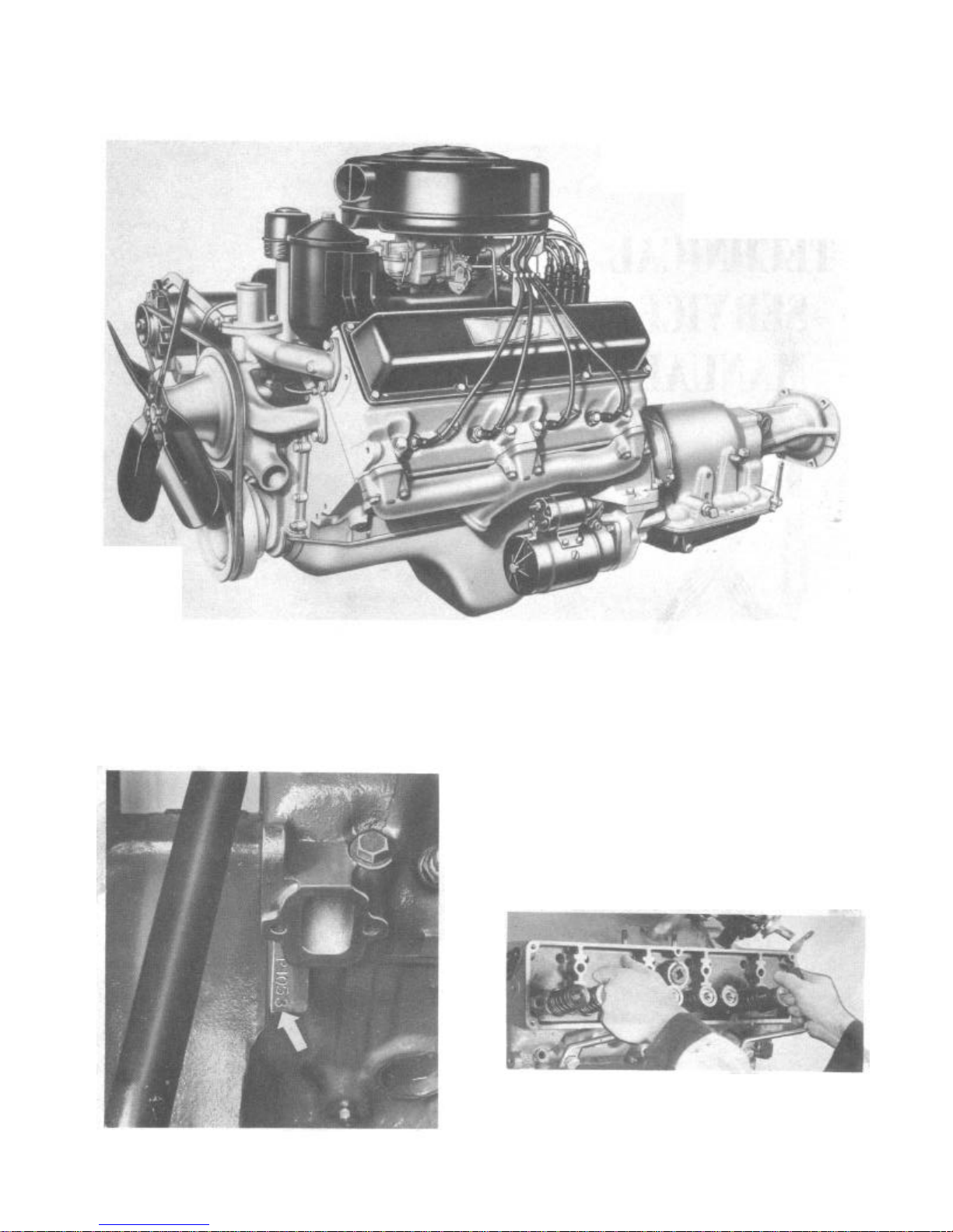
ENGINE IDENTIFICATION
The engine number is located on the upper left
hand forward portion of the cylinder block on
the "Hornet" and "Wasp" Series.
The engine number on the "Rambler" Series is
located on a machined surface on the right side
of the engine block just above the exhaust pipe.
Letter Identification, Size of Bore, Main Bearings and
Connecting Rod Bearings
In the machining of cylinder .blocks and
crankshafts, it is sometimes necessary to
machine the cylinder bores to .010" oversize,
and the crankshaft main bearing journals or
crank pins to 0.10" undersize.
These engines are marked with a three letter
code. The code is stamped adjacent to the
engine number. The letters are decoded as
follows:
First Letter Size of Bore
Second Letter Size of Main Bearings
Third Letter Size of Connecting Rod
Bearings
Letter "A" Standard
Letter "B" .010" Undersize
Letter "C" .010" Oversize
Engines (after Number F-2814 or M-3616) that
are not marked are standard in all respects.
CYLINDER HEAD AND GASKET
Whenever a cylinder head is removed, inspect
the mating surfaces on the cylinder head and
block for cleanliness and squareness with a
straight edge.
Coat the gasket with a non-hardening gasket
paste and locate the gasket on the cylinder
block. A pair of guide pins, size 3" x 1/2"-13
"Hornet" and 3" x 7/16"-14 "Wasp" Series, will
aid in the installation of the cylinder head
(Fig. 1).
Series, and the studs on "Rambler" Series, as
they connect to water passages in the cylinder
head.
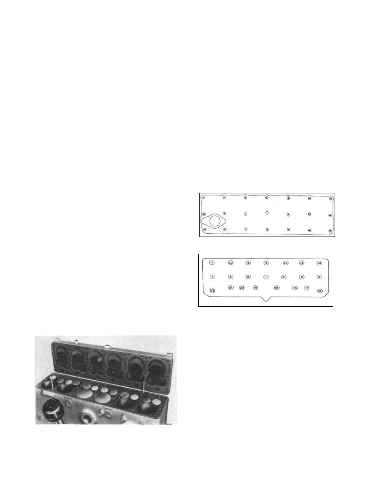
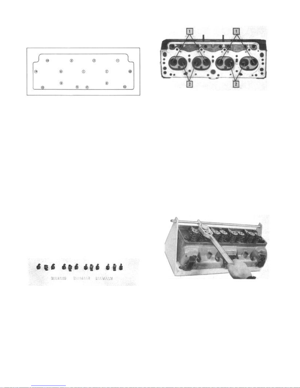
Tighten the cap screws or stud nuts with a
torque wrench in a uniform manner, following
the sequence shown in Figures 2 and 3.
The "Hornet" Series, with aluminum cylinder
head, cap screws should be drawn up to 75-80
foot pounds of torque with engine at room
temperature.
The "Wasp" Series, with cast iron cylinder
head, cap screws are drawn up to 60-65 foot
pounds of torque with engine at normal operating temperature. With aluminum cylinder head,
tighten to 60-65 foot pounds of torque with
engine at room temperature.
Tighten the "Rambler" Series stud nuts to
57-60 foot pounds torque with engine at normal
operating temperature.
FIGURE 2—"Hornet" and "Wasp" Series
Cylinder Head Tightening Sequence
FIGURE 3—Cylinder Head Tightening
Sequence "Rambler" Series
VALVES
Valve Springs
Whenever valve springs are removed, they should
be tested according to the specifications
listed below, using a valve spring tester (Fig.
4). Any spring not within the specifications
should be replaced.
FIGURE 1—Guide Pin Installation to Install
Cylinder Head
Be sure that a sealing compound is used on all
cylinder head cap screws, "Hornet" and "Wasp"
Valve Spring Specifications
Series "Hornet" "Wasp" "Rambler"
Valve Spring
Approximate
Free Height 2-1/2" 2-3/16" 2-5/32"
Valve Spring
Pressure
Valve Closed 73-81 Lbs. 40-48 Lbs. 37-41 Lbs.
@ 2-1/2" @ 1-61/64" @ 1-3/4"
Valve Open 153-165 Lbs. 16-124 Lbs. 75-82 Lbs.
@ 1-27/32" @ 1-19/32" @ 1-7/16"
Page 6
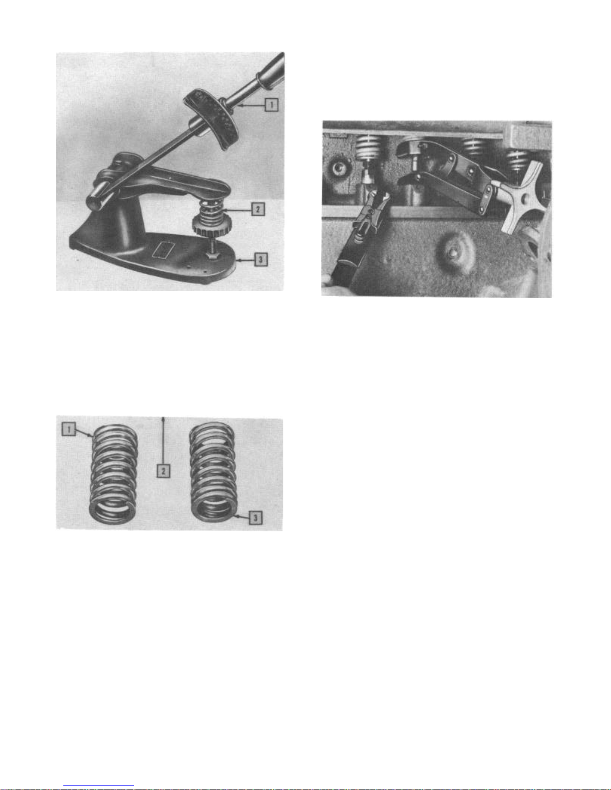
1. Torque Wrench
2. Valve Spring Tester
3. Valve Spring
ENGINE 6 CYLINDER
engine supports and loosening the rear supports. The engine may then be moved slightly
upward and to the left.
To assist in the installation of valve
locks, Tool J-1953 can be used on the "Hornet"
and "Wasp" Series (Fig. 6).
FIGURE 6—Valve Lock Installation "Hornet"
3
and "Wasp" Series
FIGURE 4—Valve Spring Tester
Valve Spring Position
The valve springs are installed with the closed
coils toward the head of the valve as shown in
Figure 5.
1. Correct Position, Closed Coils Up
2. Arrow Points to the Valve Seat
3. Incorrect Position, Closed Coils Down
FIGURE 5—Correct Position of the
Valve Spring
Valve Spring and Valve Removal
The valve springs and valves can be removed
after the manifolds (where necessary), cylinder
heads, and valve covers are removed.
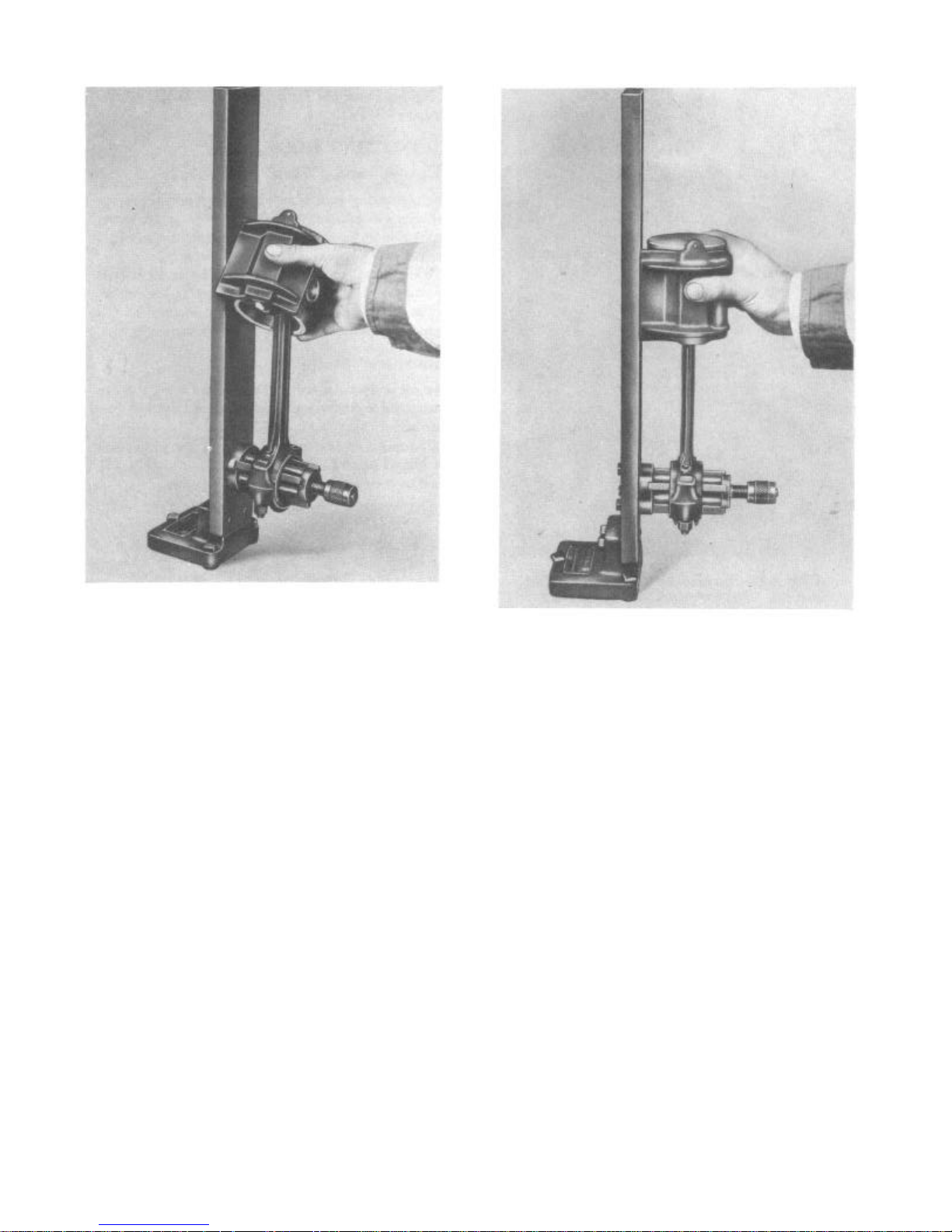
"Hornet" 6 and "Wasp" Twin-H-Power
To remove the intake and exhaust manifolds as
an assembly with the carburetors, required
additional clearance can be obtained by removing the 5/8" nut from the top of the front
"Wasp" Hi-Torque 6
Clearance permits removal of the manifolds
without movement of the engine.
"Rambler" Series
Exhaust pipe mounted to side of engine need
not be removed.
Valve Spring Compressor J-4487 ("C" Type) will
facilitate valve spring removal and replacement on the "Rambler" Series.
Valve Adjustment
After removing the intake and exhaust manifold
assembly and valve covers, the valves on the
"Hornet" and "Wasp" can be adjusted to a cold
setting clearance of .010" "go"-.011" "no-go"
on the intake valves and .014" "go"-.015"
"no-go" on the exhaust valves.
The "Rambler" valves are adjusted without
removal of the exhaust pipe to a cold setting
clearance of .016" intake valves and .018"
exhaust valves.
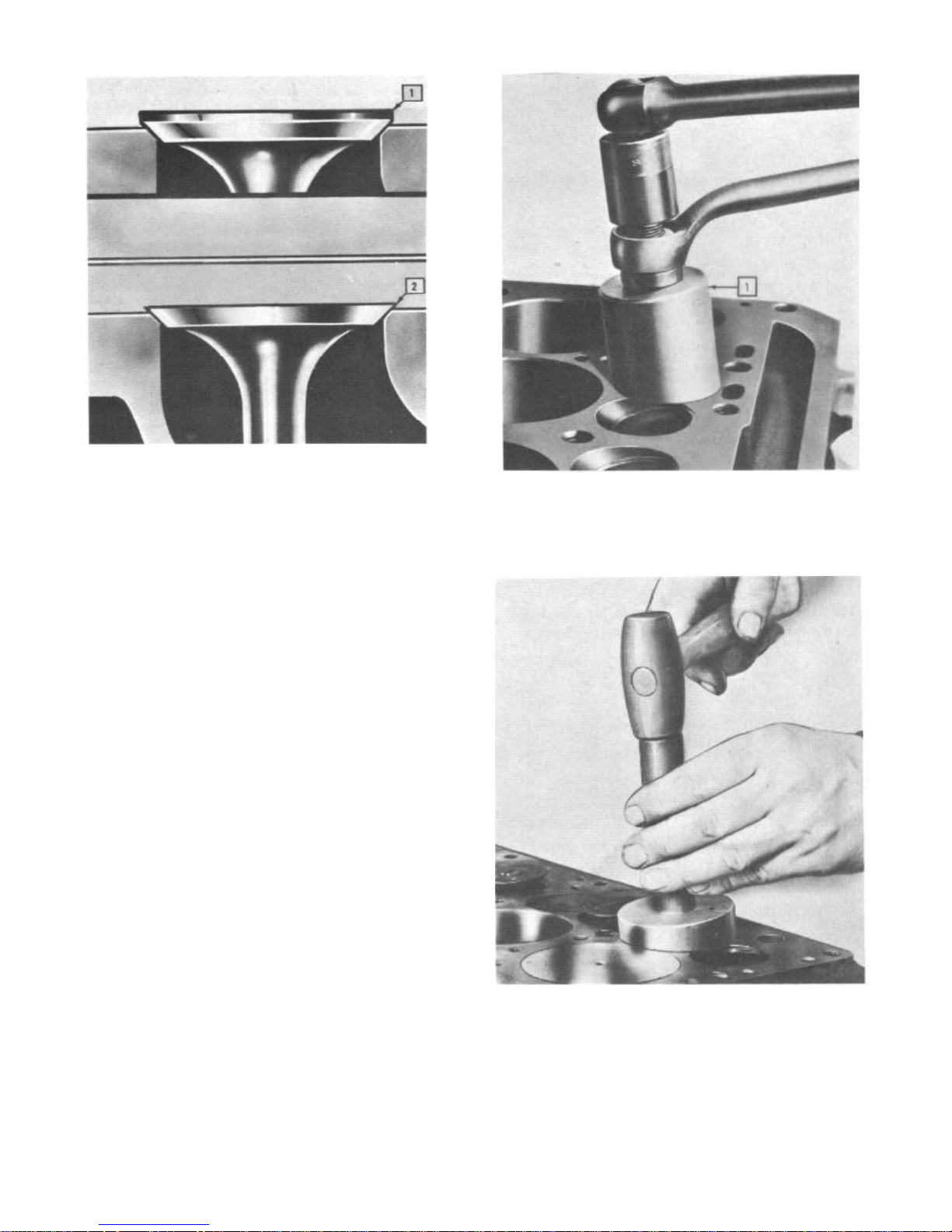
Valve Refacing
It is important when refacing valves that just
enough material be ground off to clean up the
face.
The valve should be replaced if there is less
than approximately 1/16" material, "Hornet"
and "Wasp" Series and 1/3
2" "Rambler" Series, left on outer diameter of
the valve head known as the valve head margin.
A heavy margin aids in the dissipation of heat
and helps avoid valve warpage (Fig. 7).
The "Hornet" Series intake and exhaust valve
seat and face angle is ground to 45°.
Page 7
6
TECHNICAL SERVICE MANUAL
1. Correct Valve Refacing
2. Incorrect Valve Refacing
FIGURE 7—Correct Valve Refacing
1. Valve Guide Removing Tool J-2814
The "Wasp" Series intake valve seat and
face angle is 45°. The exhaust valve seat and
face angle is 46°.
The "Rambler" Series intake and exhaust
valve face angle is 44°. The valve seat angle
is 45°.
Valve Guides
"Hornet" Series valve stem to guide clearance
is .0015"-.003" Intake, .002"-.004" Exhaust;
"Wasp" Series .001"-.003" Intake, .002".004" Exhaust; "Rambler" Series .0018".0033" Intake and Exhaust.
Replace the guides when these clearances are
exceeded. Check valve stem diameters to
determine whether or not proper stem to guide
clearance exists.
Stem diameters are:
Intake
Exhaust
“Hornet”
.3412”-.3422”
.3402”-.3412”
The valve guides can be removed through
the valve seat opening with a puller.
"Rambler" Series Tool J-2814, illustrated in
Figure 8, can also be adapted to the "Hornet"
and "Wasp" Series by using the spacers from
their respective guide installing tools.
The "Hornet" Series valve guides are
installed with Tool J-883-A (Pilot J-883-8
or 9) to insure that the guides are driven
to the correct depth of 1-3/32 for the
exhaust guides, 1-7/16" intake guides, from
the top of the guide to the top face of the
block (Fig. 9).
“Wasp”
.3412”-.3422”
3402”-.3412”
“Rambler”
.3407”-.3412
.3407”-.3412
FIGURE 8—Removing Valve Guides
"Rambler" Series
FIGURE 9—Installing Valve Guides
The "Wasp" Series valve guides are installed with Tool J-883-A (Pilot J-883-101.
The guides are inserted to a depth of 1%9"
from the top of the guide to the top face of
block.
Use Tool J-1429-A to install the "Rambler"
Page 8
ENGINE 6 CYLINDER
Series valve guides. Drive the guides flush
with the opening of the guide bore in the
block.
Valve Timing
Valve timing is determined by the relation
between the sprocket on the camshaft and the
sprocket on the crankshaft.
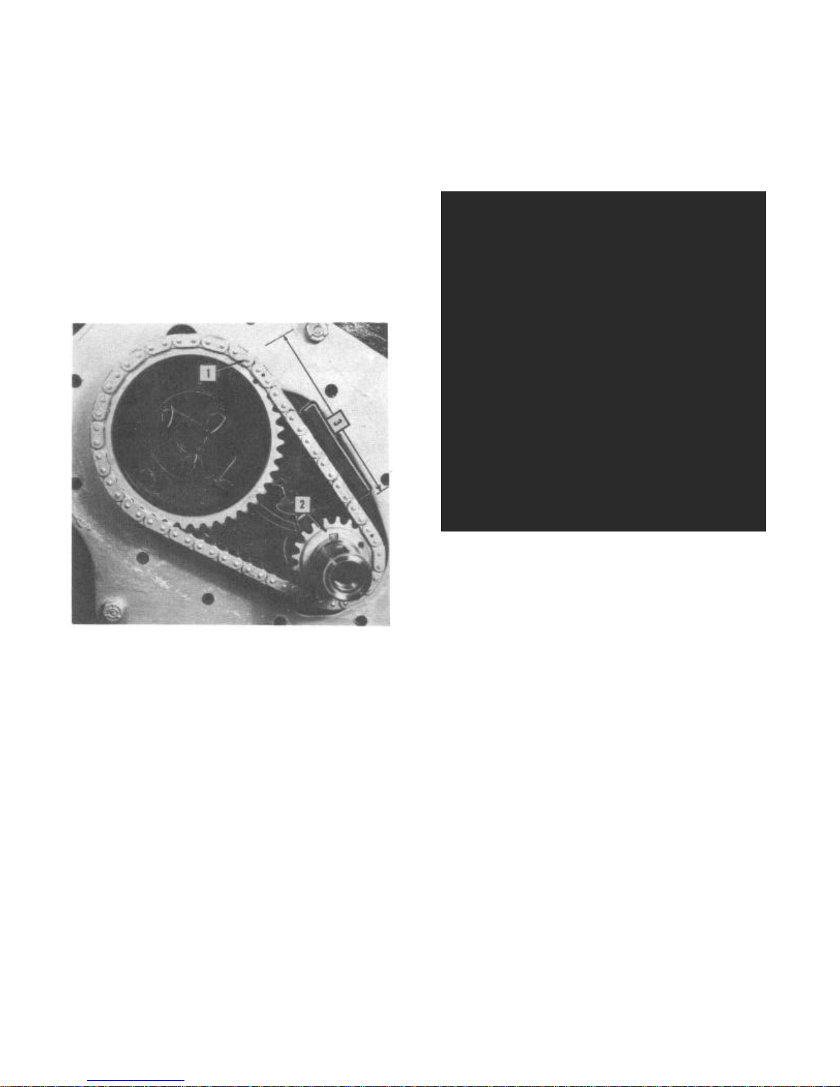
"Hornet" and "Wasp" Series
When installing timing assembly, line up the
marked teeth on the sprockets with the marked
links on the chain. Correct installation will
result in locating 7 links or 14 pins between
marks on sprockets as illustrated in Figure 10.
5
mark on the inner timing mark radius (5.06"
flywheel radius).
This distance should be 21/4" plus or minus 1/s"
for valve lash errors. One tooth off timing on
crankshaft sprocket will affect this dimension
by plus or minus 1-31/64". One tooth off on
camshaft sprocket will affect this dimension by
plus or minus 13/16".
1. Marked Tooth on Camshaft Sprocket
2. Marked Tooth on Crankshaft Sprocket
3. 7 Links or 14 Pins
FIGURE 10—Correct Timing Chain Installation
"Hornet" and "Wasp" Series
"Hornet" Series
Valve timing can be checked without dismantling the engine.
With the engine at room temperature,
locate No. 1 piston at U.D.C. exhaust stroke.
Install a dial indicator on No. 1 cylinder
exhaust valve head through spark plug opening. Crank engine slowly until dial indicator
indicates valve has seated.
Place a chalk mark on the flywheel,
through the ignition timing mark opening in
line with the lower ledge of opening.
Crank engine backwards to expose both the
chalk mark and U.D.C. mark on flywheel. (This
is only possible if timing is correct or
early.) With a pair of dividers, measure the
distance between the U.D.C. mark and chalk
FIGURE 11—Valve Timing Diagram
"Hornet" Series
"Wasp" Series
To check valve timing on the "Wasp" Series,
crank engine until No. 1 piston is at T.D.C.
exhaust stroke.
Install a dial indicator on No. 1 cylinder
exhaust valve head through spark plug opening.
Crank engine slowly until dial indicator indicates valve has seated.
Place a chalk mark on outer edge of vibration
damper below pointer.
Measure distance from chalk mark back to U.D.C.
No. 1 mark with steel scale located around
circumference of damper. This distance should be
approximately 13/4" (with cold valve lash .015")
plus or minus 1/8" for valve lash errors. If the
camshaft sprocket is off one tooth, it will
affect the dimension by plus or minus 1%2". If
the crankshaft sprocket is off one tooth, the
dimension will be affected by plus or minus
13/16".
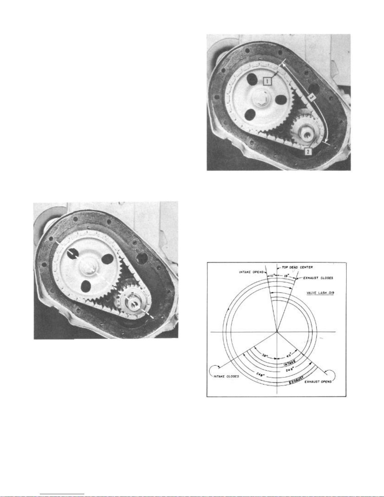
"Rambler" Series
When installing timing assembly, line up the
marked teeth adjacent to each other on a center
line drawn through the center of the camshaft
and the center of the crankshaft (Fig. 13).
Before installing the timing chain cover, check
the correct installation of the timing chain;
locate the marked tooth of the camshaft sprocket
Page 9
6
TECHNICAL SERVICE MANUAL
1. Marked Tooth on the Camshaft Sprocket
2. Marked Tooth on the Crankshaft Sprocket
3. 91/2 Links or 19 Pins
FIGURE 12—Valve Timing Diagram
"Wasp" Series
FIGURE 14—Correct Timing Chain Installation
"Rambler" Series
FIGURE 13—Place Marked Teeth on Center
Line When Installing Sprockets and Chain
"Rambler" Series
at approximately the one o'clock position.
This should place the marked tooth of the
crankshaft sprocket where it begins to mesh
with the chain (Fig. 14). Count the number
of links between the marked teeth of both
sprockets. There should be 91/2 links or 19
pins.
Valve timing may be inspected by locating
the No. 6 piston on T.D.C. in firing
position. Then set valves on the No. 1
cylinder to .003" clearance. Slowly rock the
crankshaft back and forth.
If the timing is set properly, the
exhaust valve should open before the D.C.
mark on the vibration damper lines up with
the pointer. Note this distance. The intake
valve should open an equal distance after the
D.C. mark passes the pointer.
FIGURE 15—Valve Timing Diagram
"Rambler" Series
TIMING CHAIN COVER
"Hornet" and "Wasp" Series
The timing chain cover oil seal is a leather
chevron design, spring loaded, to contact the
seal surface of the vibration damper under
Page 10
ENGINE 6 CYLINDER
7
pressure.
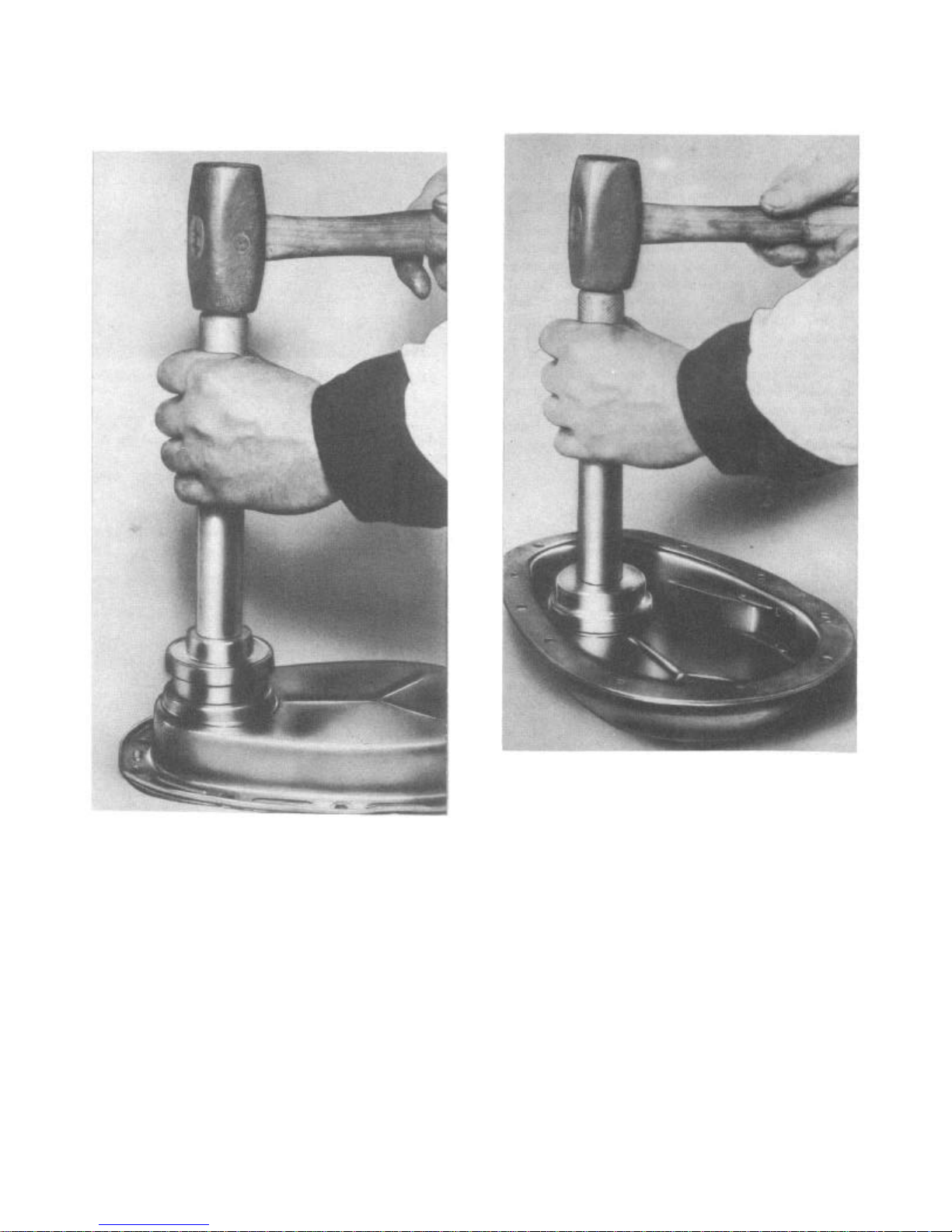
Tool J-2776 is used to remove and install
the timing chain cover oil seal (Figs. 16 and
17):
lip of leather is in good condition and
not curled over.
FIGURE 16—Removing Timing Chain Cover
Oil Seal—"Hornet" and "Wasp" Series
Insert the collar so that slot in collar
engages depression in cover. Support the
cover when driving out the seal with the
straight side of the driver.
NOTE: The tool head is reversible on the
handle. The side with the tapered pilot
is used for installing the seal and the
large size for removal. Before installing
a new oil seal, apply a coating of white
or red lead in the well of the timing
cover. Install the oil seal in cover
using tapered pilot side of tool (Fig.
17). With J-872-5, handle screw in
opposite end of tool, and with an arbor
press or soft hammer, press the seal
tightly into place. After seal is installed, recheck to make certain that the
FIGURE 17— Installing Timing Chain Cover Oil
Seal—"Hornet" and "Wasp" Series
"Rambler" Series
The timing chain cover is provided with a
felt seal to prevent the leakage of oil
around the front crankshaft pulley hub. To
prevent damage to this seal, it is important
that the cover be properly aligned when
installing the vibration damper. This is
accomplished by leaving the cover to block
screws loose until the vibration damper has
been partially installed. Then tighten the
cover screws.
At time of installation of a new seal,
the rubber section of the seal must be
installed to the rear of the cover.
The oil seal installed in the timing
chain cover is replaced by driving the old
one out from the rear and installing a new
seal and retainer from the front.
An oil slinger is used inside the timing
chain cover.
Page 11
8
The slinger is held in place by the crankshaft
sprocket and vibration damper.
TECHNICAL SERVICE MANUAL
CAMSHAFT AND BEARINGS
The camshaft is supported by four steel
shelled, babbitt lined bearings which have
been pressed into the block and line reamed.
The camshaft bearings are step bored being
larger at the front bearing than at the rear
to permit easy removal and installation of the
camshaft. All camshaft bearings are lubricated under pressure through drilled passages
in the cylinder block.
To simplify camshaft removal on the "Hornet"
and "Wasp" Series, remove the radiator core
and grille assemblies and intake exhaust
manifold. Then raise the front of the engine
slightly.
On cars equipped with air conditioning and all
"Rambler" Series, the engine should be
removed for camshaft removal.
The engines should also be removed from the
car if camshaft bearing replacement and/or
line reaming is contemplated.
Camshaft Bearing Oil Clearances
"Hornet" .0015"-.002"
"Wasp" .0005"-.0015"
"Rambler" .001"-.002"
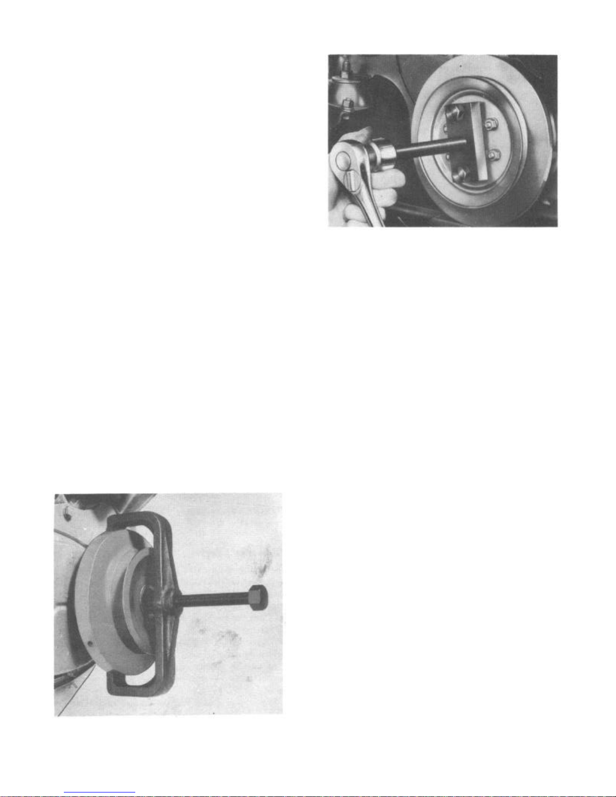
FIGURE 19—Removing Vibration Damper
Assembly "Wasp" Series
Locate engine with timing assembly lined
up as shown in Figure 10.
Remove timing chain cover and cut safety
wire from camshaft sprocket mounting bolts.
Remove camshaft sprocket and chain assembly.
Use Puller 1-471 to remove crankshaft
sprocket (Fig. 20) if a gear change is to be
made.
Camshaft Removal
"Hornet" and "Wasp" Series
Remove the radiator, radiator grille, fan
assembly, and intake and exhaust manifolds.
Pull the vibration damper pulley assembly
after removing retaining cap screw. Use
Puller J-676-C for the "Hornet" Series (Fig.
18) and J-5371 "Wasp" Series (Fig. 19).
FIGURE 20—Removing Crankshaft Sprocket
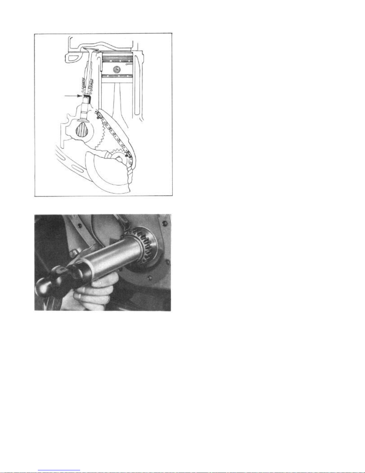
Remove valve side covers and raise valves
and springs sufficiently to install tools
1-1612-3-A tappet holders (Fig. 21). Remove
oil spout on the "Wasp" Series and spout and
chain silencer on the "Hornet" Series.
Remove camshaft thrust plate.
Remove camshaft.
To reinstall the crankshaft sprocket, if
removed, use Driver J-5369 (Fig. 22):
FIGURE 18—Removing Vibration Damper
Assembly "Hornet" Series
"Rambler" Series
Remove engine from the car. Remove fan
assembly and cylinder head. Remove valve
tappet covers and vibration damper. Remove
valves and valve springs;
Page 12
ENGINE 6 CYLINDER
End Play: .003"-.005" "Hornet" and "Wasp"
Series .004"-.006" "Rambler" Series
The camshaft end play can be checked with a
feeler gauge between the rear of the camshaft
sprocket and the front surface of the
camshaft thrust plate. A dial indicator can
also be used for checking the end play of the
camshaft.
PISTONS
"Hornet" and "Wasp" Series
The pistons are aluminum alloy cam ground
with taper ground skirt.
Ring grooves are provided for four piston
rings, two compression and two oil control
rings. One oil control ring is installed
below the piston pin while two compression
rings and one oil control ring are above the
pin. The rings are positioned and retained
in a limited working area by pins installed
in the piston ring grooves.
"Rambler" Series
9
FIGURE 21—Tool J-1612-3A Tappet Holders
FIGURE 22—Installing Crankshaft Sprocket
"Hornet" and "Wasp" Series
retain tappets with wire.
Remove timing chain cover and oil slinger.
Position engine with timing marks on a
center line (Fig. 12). Remove camshaft
sprocket retaining screw. Remove timing
chain and sprockets. The sprockets can be
pryed off of the shafts.
Remove camshaft thrust plate and camshaft.
Camshaft End Play
The camshaft end play is obtained between
the front surface on the camshaft bearing
and the camshaft thrust plate. When excessive end play occurs, a change in thrust
plate will restore the correct end play.
The pistons are aluminum alloy cam ground
having a larger diameter measured at right
angles to the piston pin hole and taper
ground skirt. A steel strut for structural
strength and to control expansion is located
in the pin boss structure.
Ring grooves are provided for four rings
above the piston pin, two compression and two
oil control rings. The piston pin is off-set
from the center axis toward the thrust side
of the cylinder.
To insure proper installation of off-set pin,
a notch is cast in top of piston. Piston must
be installed in the engine with the notch
toward the front.
Piston Removal
Piston removal is accomplished from the top
of the engine. However, before removing the
pistons, the ring ridges in the cylinder
bores must be removed. Failure to remove the
ridge at the top of the cylinder bore will
very often result in piston ring breakage and
damage to the piston groove land. If cylinder
taper exceeds .009", bore must be trued up
and oversize pistons and rings used.
Fitting Pistons
"Hornet" and "Wasp" Series
The pistons are fitted by the use of a spring
scale and feeler tape for a clearance of
.002" under a three to four pound pull.
(Parts must be clean, dry, and at room
temperature.)
"Rambler" Series
The piston is fitted so that each piston will
support its own weight in any portion of the
cylinder with all parts clean and dry. Piston
Page 13

10
TECHNICAL SERVICE MANUAL
to bore clearance is .0006" to .0012".
PISTON RINGS
The pistons are fitted with four piston
rings, two compression and two oil control
rings.
A chrome plated upper ring is used to resist
corrosion.
Before assembling the rings to the piston,
carbon must be cleaned from all ring grooves.
The oil drain holes in the oil ring grooves
must be cleared. Care must be exercised not
to remove metal from the grooves, since that
will change their depth, nor from the lands,
since that will change the ring groove
clearance and destroy ring to land seating.
Checking Ring Groove Clearance
Side groove clearance is measured with a
feeler gauge. Roll the rings around the
piston in the grooves in which they operate.
Check for freedom all the way around.
The groove clearances are listed below by
ring number with the top ring as number one.
Ring Number 1 2 3 4
"Hornet" .002"-.004" .002"-.004" ,001"-.003" ..001"-.003"
"Wasp" .002"-.004" .002"-.004" .001"-.003" .001"-.003"
"Rambler" .002"-.004" .002"-.004" .002"-.004" .002"-.004"
Rings must be installed on pistons with a
ring installation tool to prevent distortion
and ring breakage.
Detailed instructions in service ring packages must be followed.
"Hornet" and "Wasp" Series
Four piston rings are used; three rings are
located above the piston pin and one below
the pin. The rings are pinned in place to
prevent movement (Figs. 23 and 24).
Checking Ring Gap Clearance
Piston ring gap clearance is measured in the
bottom of the cylinder near the end of the
ring travel area. To square the ring in the
bore for checking gap clearance, place the
ring in the bore. Then, with an inverted
piston, push the ring down near the lower end
of the ring travel area. When other than
standard ring sizes are used, rings should
be individually fitted to their respective
bores.
The ring gaps for fitting rings are listed below:
"Hornet" .006"-.014"
"Wasp" .004"-.009"
"Rambler" .010"-.020"
Piston Ring Installation
Removal of glaze from the cylinder wall for
quicker ring seating can be accomplished by
various methods. If the expanding flexible
type hone is used, do not use more than 10
strokes (each stroke down and return) to
recondition a cylinder wall.
Successful ring installation depends upon
cleanliness in handling parts and while
honing the cylinder walls. The engine bearings and lubrication system must be protected
from abrasives.
Rigid type hones are not to be used to
remove cylinder glaze as there is always a
slight amount of taper in cylinder walls
after the engine has been in service.
FIGURE 23—Ring Arrangement
"Hornet" Series
The rings are notched on the inner diameter
at the gap slot. The width of the notch is
.125". Approximately .075" is at one end of
the ring and .050" at the other end. This
off-setting of the notch enables a single pin
pressed in from the top of the piston to
locate the three top rings without having the
gaps on adjacent rings aligned (Fig. 25).
Page 14

ENGINE 6 CYLINDER
CAUTION: Because of the backlash clearance requirement, it is suggested that
no ring be filed to fit a bore size
smaller than the ring size.
"Rambler" Series
The two compression and two oil control rings
are located above the piston pin. The
compression rings are of the "twist" design
with an inner groove installed to the top of
piston. A conventional oil control ring is
used in the third ring groove.
11
FIGURE 24—Ring Arrangement
"Wasp" Series
FIGURE 25—Pinning of Piston Rings "Hornet"
and "Wasp" Series
The end gap is equal to the backlash of the
ring notch on pin. Therefore, if the ends of
a ring are filed to obtain the correct ring
end gap, the notch has to be filed enough to
provide the backlash in equal amount.
1. Inner Groove Up
2. Oil Control Ring
3. Oil Control Ring "U" Flex
FIGURE 26—Ring Installation
"Rambler" Series
The "U" flex oil control ring used in the
lower oil control ring groove, as original
equipment, differs from all other rings. The
normal free diameter of this ring is 1/8" to
3/1_6" larger than the bore diameter in which
it is installed. Installation is outlined in
Figures 27, 28, 29, and 30.
Before installing piston in engine,
arrange ring gaps 180° apart, being sure no
gap is over the piston pin.
Service Ring Sets
For service ring replacement, follow detailed instructions enclosed in the ring
package.
Page 15

12
TECHNICAL SERVICE MANUAL
FIGURE 27—Step 1—Place "U" Flex Ring in
Bottom of Oil Ring Groove. Lubricate all
Rings and Piston Skirt with a Light
Grade Engine Oil. Butt Ends of
"U" Flex Ring Together
FIGURE 28—Step 2—Keep Ends of "U" Flex
Ring Butted Together and Place Compressor
Over Piston, Either a Constricting Band
or Split Sleeve Type Compressor
can be Used
FIGURE 30—Step 4—Make Sure Compressor
Rests Squarely on Top of Block, and
Push or Tap Piston into Cylinder
CAUTION: If Piston Does not Enter
Cylinder without Excessive Force, Remove Piston Assembly and Examine Rings
for Ring Interference.
PISTON PINS
"Hornet" and "Wasp" Series
Full floating type piston pins are used. They
are retained in the piston by two circular
lock rings, one at each end of the pin. The
piston pin fit in the connecting rod bushing
is a hand push fit at room temperature (70°).
The piston pin fit in the piston is a
hand push fit in a heated piston. Heat piston
in water or electric furnace to 200°F.
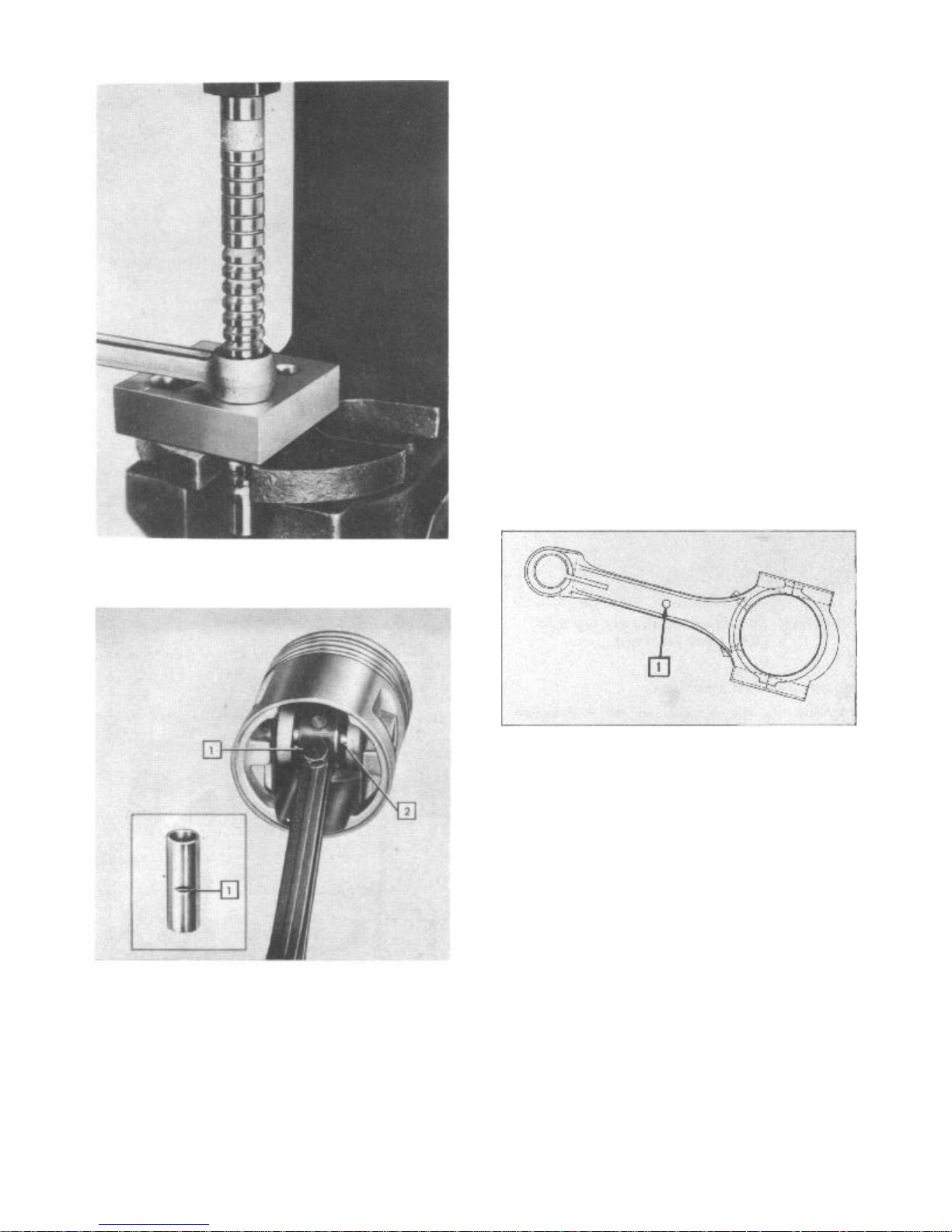
The piston pin bushings are steel back
bronze. To remove and replace, press out old
bushing, using burnisher block tool J-2950
and remover J-2948 for the "Hornet" Series,
and J-2951 and J-2948 "Wasp" Series. Install
new bushing with same tools making sure oil
holes in bushing and rod are in alignment.
Burnish bushing with block J-2950 and burnisher J-2791 "Hornet" Series, and J-2951 and
J-2949 "Wasp" Series (Fig. 31).
The bushing should be reamed .0003"
larger than its matching pin diameter. Check
the fit by holding the piston with the
connecting rod in a horizontal position. The
rod should just turn on the pin under its own
weight.
FIGURE 29—Step 3—Tighten Ring Compressor
if Band Type is Used. If Sleeve Type is Used,
BE SURE THAT IT IS NOT PULLED
HIGHER THAN THE TOP OF THE
PISTON. However, it Should be
Drawn up High Enough to
Cover all of the Rings
The standard piston pin dimensions are:
“Hornet”
“Wasp”
Length
2.942" — 2.932"
2.4375" + or
—.005"
Diameter
.9687" — .96845"
.7499" + .000"
—.00025"
"Rambler" Series
The piston pin is locked in place in the
connecting rod by means of a locking bolt
(Fig. 32).
To fit the piston pin, hone the connecting rod to fit the pin. Then hone the piston
to allow a thumb press
Page 16
ENGINE 6 CYLINDER
Tighten piston pin clamp screw to 18-22
foot pounds torque.
CONNECTING RODS
"Hornet" and "Wasp" Series
The connecting rods have oil squirt holes to
provide cylinder wall lubrication, at low and
idle speed, to the thrust side of the
cylinders. An oil hole on the top of the rod
supplies lubrication to the piston pins.
When installing connecting rods, the
squirt hole is toward the camshaft side
(thrust side) of the engine.
The cylinder location numbers are stamped
on the connecting rod and caps during initial
assembly.
"Rambler" Series
Two oil squirt holes are provided in the
upper rod cap section for cylinder wall
lubrication at low and idle speeds.
The notch on the top perimeter of the
piston and the identification boss on the
connecting rod (Fig. 33) must be installed
to the front of the engine.
13
FIGURE 31—Burnishing Connecting Rod
Bushing "Hornet" and "Wasp" Series
1. Locking Bolt and Notch
2. Piston Pin
FIGURE 32— Piston Pin "Rambler" Series
fit or .0002" maximum loose fit in piston at
room temperature (70°F.).
The standard piston pin dimensions are:
Length 2.755", Diameter .8598"-.8595".
1. Identification Boss
FIGURE 33—Connecting Rod Identification
Boss "Rambler" Series
The connecting rods are stamped by cylinder number location during initial assembly.
Always assemble the rods and caps with the
cylinder location numbers on the same side.
Connecting Rod Alignment
Whenever new rings are installed or new
piston pins are replaced, it is necessary to
align the connecting rods and pistons, as
assemblies, to insure true operation in the
cylinder bore.
Misaligned rods will cause uneven piston
and ring wear which will result in oil
consumption and noise. The connecting rod
should be inspected for a twisted or bent
condition (Figs. 34 and 35).
Always bend beyond the true alignment
position and then bend back to straighten so
the stresses and strains in the rod material
are relieved. If the stresses are not
relieved, the rod will not hold its alignment
after installation in the engine.
Page 17
14
TECHNICAL SERVICE MANUAL
FIGURE 34—Checking Connecting Rod
Alignment for Twist
Connecting Rod Bearings
The connecting rod bearings are the steel
backed babbitt lined precision type. They are
installed as pairs in connecting rod and cap.
CAUTION: Never file a connecting rod or
cap to adjust bearing clearance.
If the bearing clearance is excessive,
the correct connecting rod undersize bearing
set must be installed. The correct connecting
rod bearing clearance is .0005" to .0015"
"Hornet" and "Wasp" Series and .001" to
.0015" on "Rambler" Series.
To determine the amount of bearing
clearance, use a piece of Plastigage in the
bearing cap as shown in Figure 36. Then
tighten the cap to the torque specification
to compress the gauge.
Remove the bearing cap and calibrate the
width of the Plastigage with the scale
furnished as shown in Figure 37.
Connecting Rod Bearing Caps
FIGURE 35—Checking Connecting Rod
Alignment for Bend
It is important that the connecting rod cap
bolt nuts be drawn up to the correct tension.
Tighten to:
"Hornet" 40-45 Ft. Lbs.
"Wasp" 40-50 Ft. Lbs.
"Rambler" 27-30 Ft. Lbs.
FIGURE 36—Plastigage in Place in the
Bearing Cap
Page 18
ENGINE 6 CYLINDER
FIGURE 37—Measure the Width of the
Plastigage Scale
Reduce torque 15 per cent if threads are
oily
The notches on the lower and upper rod
caps should be to the same side of engine
with the squirt hole on upper cap to camshaft
side of engine on the "Hornet" and "Wasp"
Series.
The cylinder numbers are to the camshaft
side of the engine and the identification
mark (Fig. 33) to the front of engine on the
"Rambler" Series.
Connecting rod side clearance:
"Hornet" and "Wasp" .007" — .013"
"Rambler" .005" — .015"
CRANKSHAFT
"Hornet" and "Wasp" Series
The crankshaft is supported by four main
bearings with the end thrust taken at the No.
3 bearing position.
The crankshaft, flywheel, and vibration
damper are balanced as individual units.
Complete engine assemblies are then balanced
with all reciprocating parts in motion.
Replacement of vibration damper or flywheel
can be accomplished without rebalancing the
complete assembly.
15
caps should never be filed.
When either half of a bearing requires
replacement, a complete set should be installed. To replace the upper half of a
bearing, remove the bearing cap of the
bearing to be replaced. Then loosen all of
the other bearing caps and insert a small pin
in the crankshaft oil hole. The head of the
pin should be large enough so that it will
not fall into the oil hole, yet thinner than
the thickness of the bearing (Fig. 38).
FIGURE 38—Removing Main Bearing Insert
With the pin in place, rotate the shaft so
that the upper half of the bearing will
rotate in the direction of the locating
tongue on the bearing.
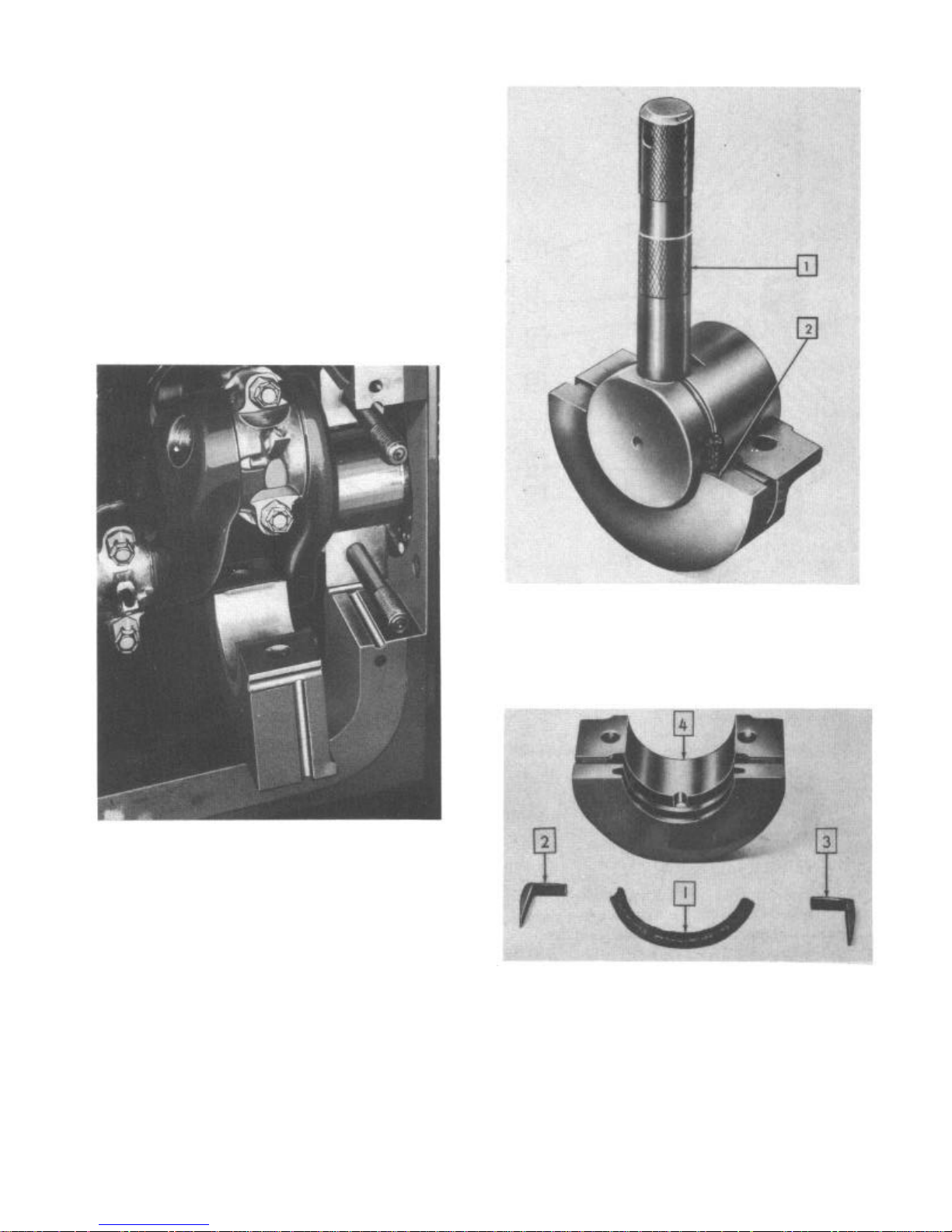
Tool J-2955 will greatly facilitate front and
rear bearing cap removal on the "Hornet" and
"Wasp" Series (Fig. 39).
CAUTION: Care must be exercised on
removal of the front main bearing cap
because if the front engine end plate
gasket is damaged, a replacement requires the removal and replacement of
timing assembly and front engine end
plate.
"Rambler" Series
The crankshaft is supported by four main
bearings with the end thrust taken at the
front main bearing location.
The component parts of the crankshaft
assembly are individually balanced; then
rebalanced as an assembly.
Replacement of vibration damper or flywheel can be accomplished without rebalancing
the complete assembly.
Crankshaft. Main Bearings
Main bearings are of the precision type
having a steel back with a babbitt lining.
The bearings are not adjustable. Shims should
never be used and the bearing
FIGURE 39— Removing Front Min Bearing
Cap with Tool J-2955 "Hornet" and
"Wasp" Series
Page 19
Crankshaft Main Bearing Clearance
The standard clearance of .0005" to .0015"
on the "Hornet" and "Wasp' Series and .001"
to .0015" "Rambler" Series can be accurately
checked by the use of Plastigage.
NOTE: When checking bearing clearance
with the engine in such a position
that the bearing caps support the
weight of the crankshaft and flywheel, keep all main bearing caps
tight except the one being checked.
Support the weight o f the crankshaft
with a jack.
Remove the bearing cap and wipe the oil
from the bearing insert.
Place a piece of Plastigage across the
full width of the bearing insert (Fig. 36).
Reinstall the bearing cap and tighten
75-80 foot pounds torque (dry) on the
"Hornet" and "Wasp" Series and 66-70 foot
pounds torque (dry) on the "Rambler" Series.
Then remove the bearing cap and with the
graduated scale, which is printed on the
plastigage envelope, measure the width of the
flattened plastigage at its widest point
(Fig. 37). The number within the graduation
indicates the clearance in thousandths of an
inch. Install the proper size bearing liners
(inserts) to bring the clearance to standard.
Before installing crankshaft or main bearing
inserts, the journals must be inspected for
condition and dimensions.
Main Bearing Journals
Main journals can be measured without removing the crankshaft from the engine block.
There are various gauges for this use, one
of which is shown in Figure 40.
Then release the plunger so that it is up
against the journal and lock the adjusting
screw in position. Remove the gauge carefully
and double the micrometer reading across the
pin and anvil in the center of the
"V". This reading is the diameter of the
journal.
Always check the journal at both ends for
taper. Then rotate the shaft 90° and measure
for out-of round. The out-of-round and taper
limit is to be held to .001".
Main Journal
Series Diameter
"Hornet" 2.4988"-2.4998"
"Wasp" 2.4988"-2.4998"
"Rambler" 2.4791"-2.4798"
Connecting Rod Bearing or
Series Crankpin Diameter
"Hornet" 2.1244"-2.1254"
"Wasp" 1.937" -1.938"
"Rambler" 2.0948"-2.0955"
Main bearing caps are recessed into the
engine block and line reamed. Therefore, it
is not practical to replace them in the field.
Crankshaft End Play
The "Hornet" and "Wasp" Series end thrust of
.003" to .009" is taken at the No. 3 main
bearing. The "Rambler" Series end thrust of
.003" to .008" is taken at the flanged front
main bearing.
MAIN BEARING OIL SEALS
"Hornet" and "Wasp" Series
The rear main bearing oil seal is a metal
backed neoprene lined seal made in two
identical halves. The upper half can be
removed without removing the crankshaft by
removing the rear main bearing cap and
applying pressure against the metal part of
the seal with a 1/4" brass rod. At the same
time, rotate the flywheel to assist in
removing the seal.
At time of installation of the seals, coat
the groove of the seal with non-hardening
sealer.
FIGURE 40—Measuring Main Bearing Journal
To operate this gauge, remove the main
bearing cap and place the gauge against the
crankshaft journal
1. Packing Groove
2. Oil Seal
FIGURE 41—Rear Main Bearing Oil Seal
"Hornet" and "Wasp" Series
Page 20
ENGINE 6 CYLINDER
After the rear main bearing cap is replaced,
cotton waste must be driven into the vertical
packing holes to seal the side of the cap. A
punch smaller in diameter than the vertical
holes and at least 4" long will facilitate
the packing of the cotton waste. Enough
packing must protrude to seal between the pan
gasket and bearing cap.
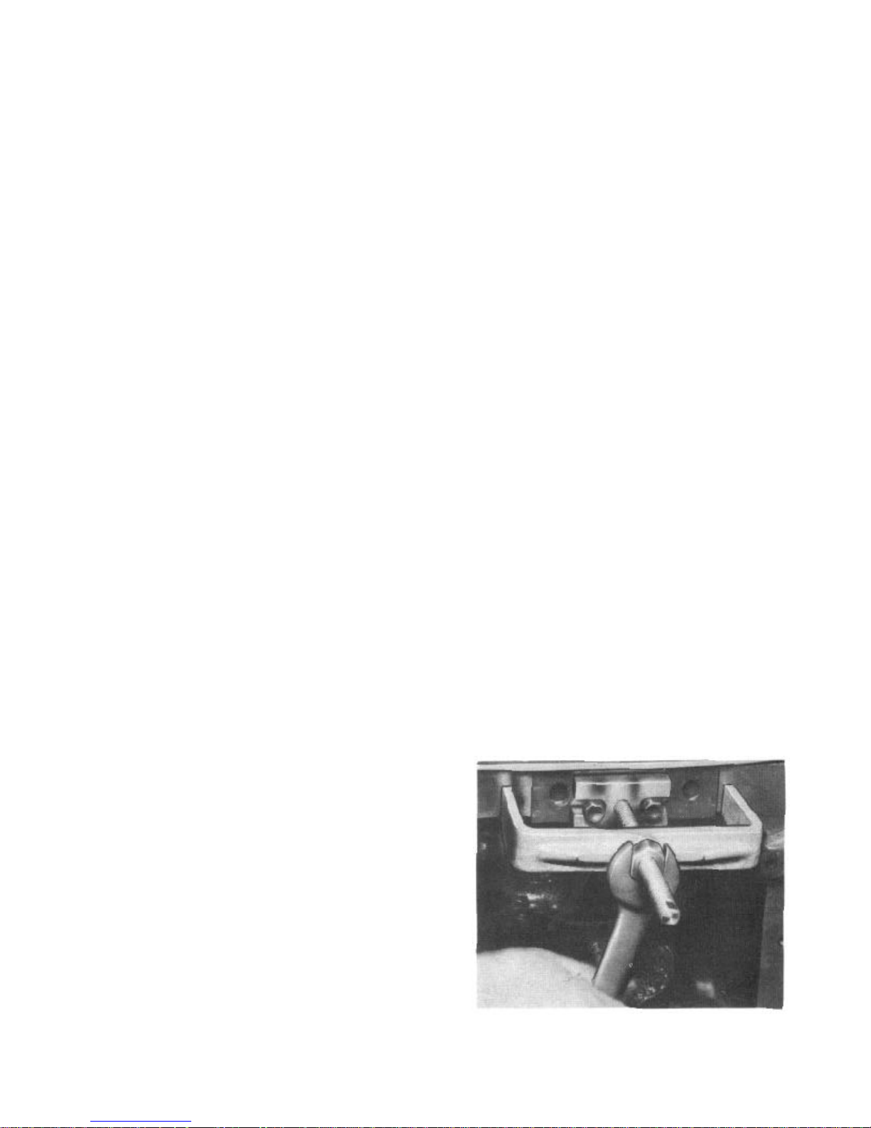
The front main bearing cap has both a
horizontal and a vertical seal to prevent
external oil leakage. This packing seals from
leakage between the engine front end plate
gasket and the bearing cap. The vertical
grooves are packed before the horizontal
grooves (Fig. 42).
17
FIGURE 42— Front Bearing Cap Oil Seal
Groove Locations "Hornet" and
"Wasp" Series
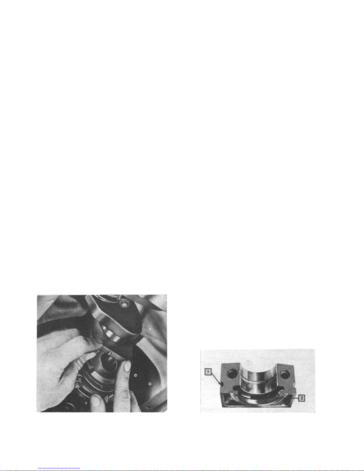
"Rambler" Series
A hemp packing and "L" shaped neoprene rubber
type rear main bearing oil seals are used. A
special tool J-1610 is required to install
the hemp packing (Fig. 43) . To properly
replace upper hemp packing, the crankshaft
must be removed.
VIBRATION DAMPER
"Hornet" Series
The vibration damper (Fig. 45) on the "Hornet"
Series has two punch marks for alignment to
maintain proper balance when the damper is
disassembled for replacement of rubber discs.
2. Point at which Packing is Cut Flush
1. Oil Seal Installing Tool J-1610
FIGURE 43—Installing Hemp Packing Oil Seal
in Rear Main Bearing Cap "Rambler"
Series
1. Hemp Packing
2. Cap Side Seal
3. Cap Side Seal
4. Main Bearing Cap
FIGURE 44— Rear Main Bearing Cap and Seals
"Rambler" Series
Pulley Remover J-676-C and Replacer J-483
will facilitate removal and replacement
operations (Fig. 18).
Page 21
18
TECHNICAL SERVICE MANUAL
1. Outer Member 5. Spacer
2. Rubber Discs 6. Oil Seal
3. Inner Member 7. Retainer Plate
4. Damper Cap Screw
FIGURE 45—Vibration Damper "Hornet"
Series
Tighten damper cap screw to 100-120 foot
pounds torque.
"Wasp" Series
The vibration damper has an off-set screw
location to insure proper reassembly for
balance in the event disassembly was made to
replace rubber cushions.
Pulley Remover J-5371 and Replacer J-5369
will facilitate removal and replacement
operations (Fig. 19)
Tighten damper cap screw to 80-90 foot
pounds torque.
"Rambler" Series
The vibration damper is not adjustable. The
screws that retain the rubber are drawn up
to a point where the shoulders will limit the
tension of the rubber blocks (Fig. 47).
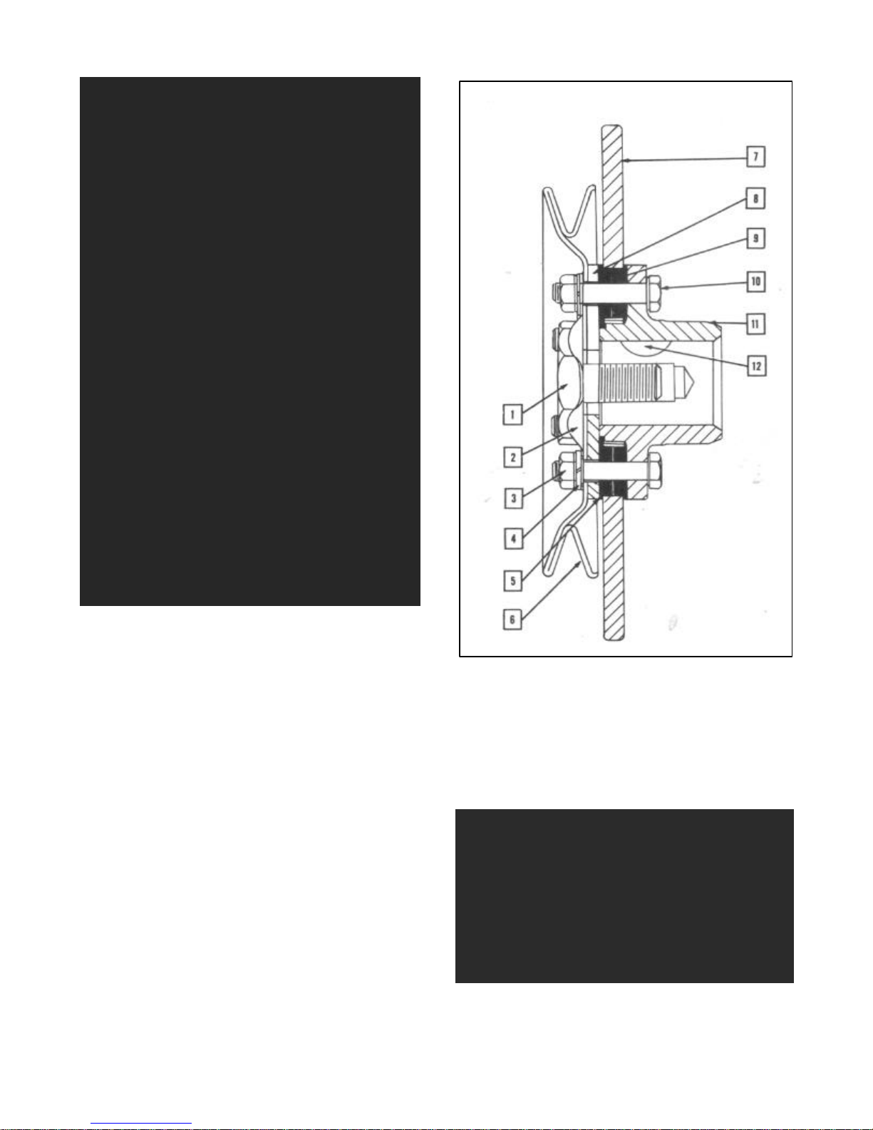
1. Damper Cap Screw 8. Damper Cover Plate
2. Cap Screw Lock 9. Rear Damper Cushion
3. Nut 10. Pulley to Damper
4. Lockwasher Screw
5. Front Damper Cushion 11. Hub
6. Damper Pulley 12. Key
7. Damper
FIGURE 46— Vibration Damper "Wasp" Series
FIGURE 47—Vibration Damper "Rambler"
Series
Tighten damper cap screw to 100-110 foot
pounds torque
Page 22
ENGINE 6 CYLINDER
19
STARTER RING GEAR
With the exception of the flywheel, as used
with the automatic transmission, which is a
steel stamping, the starter ring gear can be
replaced by placing the flywheel in an arbor
press with steel blocks equally spaced around
the gear and pressing the flywheel through,
or the ring gear can be broken with a chisel.
To install the new starter ring gear, first
heat it to expand the inside diameter so that
it can be pressed over the flywheel.
SHAFT PILOT BEARING
The pilot bearing for the shaft is located
at the center of the rear end of the
crankshaft. This is an oil impregnated bronze
bearing. It is pressed into the end of the
crankshaft. This bearing does not require any
lubrication after assembly. When assembled
in service, it is advisable to place a small
amount of high melting point grease on the
end of the shaft as it is installed into the
bearing. Bearings being installed must be of
the correct size for the series and type of
transmission.
LUBRICATION SYSTEM
The lubrication system is of the full
pressure type with all vital moving parts
receiving lubrication under pressure except
the piston pins.
"Hornet" and "Wasp" Series
The pressure is supplied by a positive
displacement rotor type oil pump mounted on
the right lower side of cylinder block and
driven from a gear cut on the camshaft.
The oil is drawn through the floating oil
intake screen (Fig. 48) to the intake side
of the oil pump.
Oil under pressure passes the plunger of
the oil relief valve assembly and fills the
main horizontal oil gallery from which it is
directed through drilled passages to lubricate the camshaft bearings, tappet assembly,
main and connecting rod bearings, cylinder
walls, and timing assembly.
Piston pins are lubricated by oil "throwoff" from rotating parts and wiping action
of piston rings.
Before removing the oil pump, position the
engine crankshaft so that No. 1 cylinder
piston is at T.D.C. exhaust stroke and No. 6
cylinder piston is at T.D.C. on compression
stroke.
Upon disassembly of the oil pump, remove
the oil pump cover and use a brass drift to
mark an indexing point of one lobe and notch
on rotor and internal gear or outer rotor to
insure relationship for reassembly.
Measure the clearance between a lobe and
notch opposite the reference mark. This
clearance should be .010" or less. If more
than .010", replace both rotors and shaft.
Place a straight edge across the pump body
between the screw holes. Use a feeler gauge
to measure the clearance between the top of
the rotors and the straight edge. This
clearance should be .004" or less. If the
clearance is greater than this limit, the
pump body must be replaced.
With the outer rotor pressed against one
side of the pump body, measure the clearance
between this rotor and the body on the
opposite side. If this clearance is more than
.008", replace the pump body.
The pump cover plate must be smooth and
not worn from the rotors. Place a straight
edge across the cover. If a .002" feeler can
be inserted between the cover and the
straight edge, the cover is worn and must be
replaced.
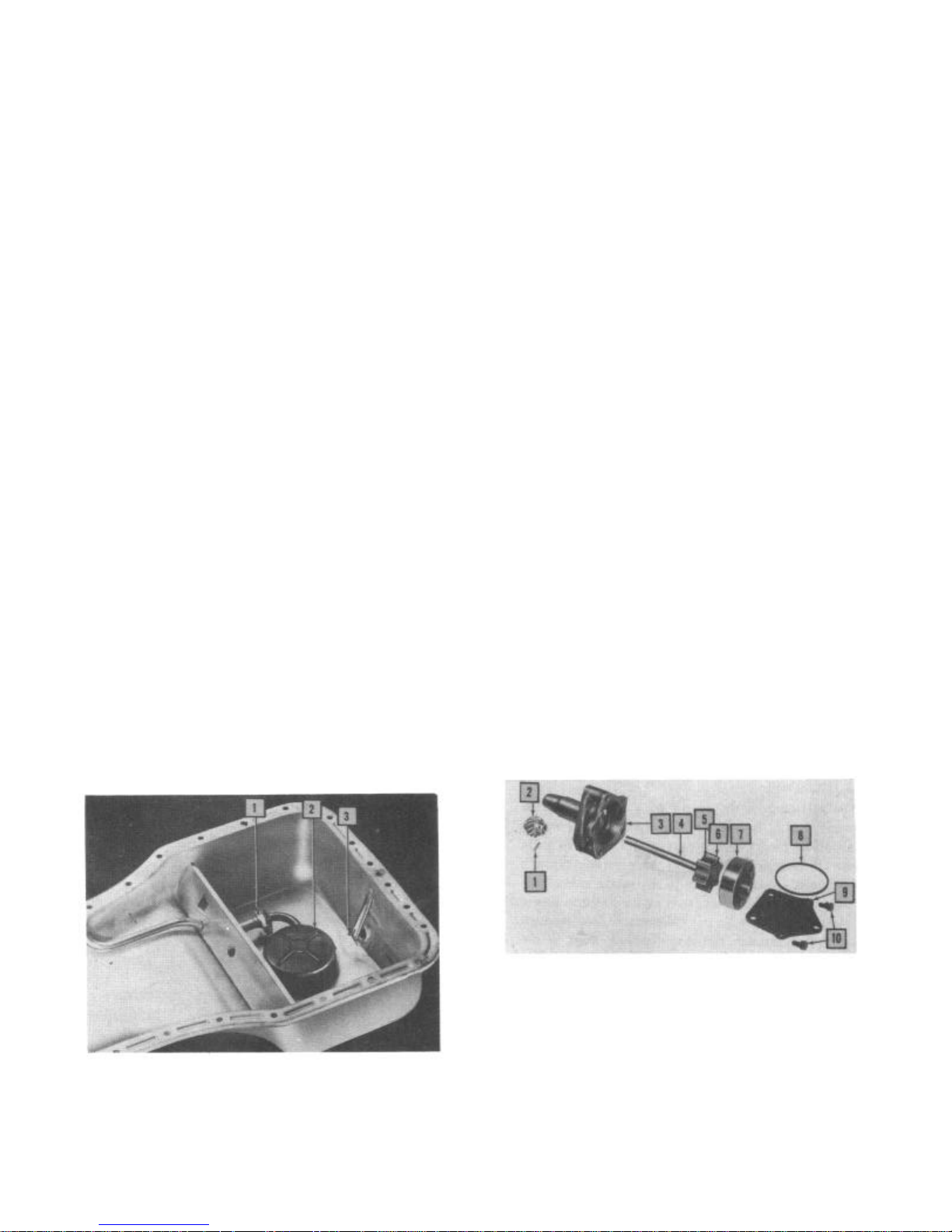
1. Swivel Connectlon
2. Intake Screen
3. Drain Plug Outlet
FIGURE 48— Oil Intake Screen Assembly
"Hornet" and "Wasp" Series
1. Oil Pump Drive Gear Pin
2. Oil Pump Drive Gear
3. Oil Pump Body
4. Oil Pump Shaft
5. Oil Pump Inner Rotor
6. Inner Oil Pump Rotor Lobe
7. Outer Oil Pump Rotor
8. Oil Pump Cover Gasket
9. Oil Pump Cover
10. Oil Pump Cover Screws
FIGURE 49—Oil Pump Assembly "Hornet"
and "Wasp" Series.
Page 23
20
TECHNICAL SERVICE MANUAL
In the event the engine crankshaft was not
moved, replacement of the oil pump presents
no problem. However, if the crankshaft was
moved, the following procedure can be used
to insure basic distributor timing location
inasmuch as the distributor is driven by the
oil pump shaft.
Crank the engine until the No. 1 cylinder
piston is on T.D.C. exhaust stroke and No. 6
is on T.D.C. in firing position.
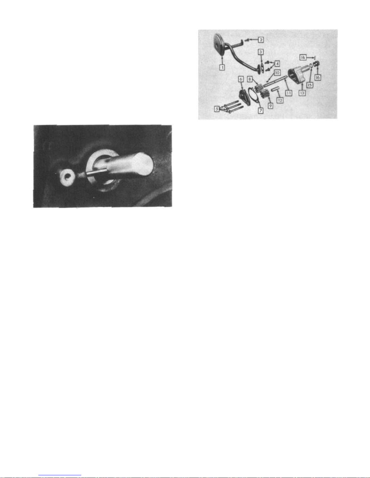
Install Aligning Tool J-2794 so that the
guide pin indexes with the distributor
mounting screw hole (Fig. 50).
1. Screen and Retainer 9. Idle Gear
2. Bolt 10. Key
3. Inlet Tube Gasket 11. Oil Pump Drive Shaft
4. Bolts 12. Oil Pump Idle Shaft
5. Cap Screws 13. Oil Pump Body
6. Oil Pump Cover 14. Oil Pump Drive Gear Pin
7. Gasket 15. Thrust Washer
8. Drive Gear (In Pump) 16. Oil Pump Drive Gear
FIGURE 51— Oil Pump "Rambler" Series
FIGURE 50—Oil Pump Shaft Aligning Tool
Install the oil pump, indexing the slot
in the pump shaft with the tang on aligning
tool, and push out the tool.
Install distributor with rotor aligned
with terminal in distributor cap which leads
to No. 6 cylinder spark plug.
"Rambler" Series
The oil pump is mounted on the right hand
side of the cylinder block. It is of the
positive displacement gear type.
The oil pump is driven off of a gear cut
on the camshaft and in turn drives the
distributor by means of an off-set tang which
is part of the oil pump main shaft. Oil is
drawn from the oil pan reservoir through a
fixed inlet screen assembly to the intake
side of the oil pump. The oil is discharged
under pressure past a relief valve in the
main oil gallery and then through holes
drilled through the main bearing webs to the
crankshaft and camshaft main bearing locations. The crankshaft drillings provide
lubrication from the main bearings to the
connecting rod bearings. The front camshaft
bearing permits oil to flow onto the timing
gear and chain assembly.
The valve tappets and piston pins are
lubricated by crankshaft oil "throw-off" and
vapors.
CAUTION: Always maintain a tight
connection between the oil pump inlet
flange and oil inlet hole located on
the right side at the bottom of the
cylinder block
The position of the oil pump drive gear
keyway should be noted before removal of oil
pump. Installing in the same location will
prevent disturbance of distributor timing.
In the event the crankshaft has been moved,
crank the engine until No. 1 cylinder is at
T.D.C. in firing position. The keyway will
be located at approximately the three-thirty
o'clock position, viewed from the lower
section of the pump body.
Oil Pressure Relief Valve
The oil pressure relief valve consists of a
plunger, spring, and retainer.
The valve is located on the left side of
the cylinder block on the "Hornet" and "Wasp"
Series and the right side of the cylinder
block on the "Rambler" Serieas.
The oil pressure relief valve is not
adjustable. A setting of 40 P.S.I. for the
"Hornet" and "Wasp" Series and 50-58 P.S.I.
for the "Rambler" Series is built into the
tension of the spring.
1. Housing Plug 3. Spring
2. Gasket 4. Plunger
FIGURE 52— Oil Pressure Relief Valve
"Rambler" Series
Page 24

ENGINE 6 CYLINDER
ENGINE SPECIFICATIONS
21
Series
Type
No. Cylinders
Bore
Stroke
Compression Ratio
(Standard)
(Optional)
Piston Displacement
Compression Pressure
at Cranking Speed
Horsepower
Twin Carburetor
Engine Lubrication
Series
Stem Diameter
Intake
Exhaust
"Hornet"
L-Head
6
3-13/16"
41/2"
7.5:1
308 Cu. In.
100 P.S.I. Min.
160 @
3800 R.P.M.
170 @
4000 R.P.M.
Pressure
VALVE SPECIFICATIONS
"Hornet"
.3412"-.3422"
.3402"-.3412"
"Wasp"
L-Head
6
3"
43/4"
7.5:1
8.0:1
202 Cu. In.
100 P.S.I. Min.
115 @
4000 R.P.M.
126 @
4000 R.P.M.
Pressure
"Wasp"
.3412"-.3422"
.3402"-.3412"
"Rambler"
L-Head
6
3W'
41/4"
7.32:1
195.6 Cu. In.
120 P.S.I.
90 @
3800 R.P.M.
Pressure
"Rambler"
.3407"-.3412"
.3407"-.3412"
Stem to Guide Clearance
Intake
Exhaust
Head Diameter
Intake
Exhaust
Seat Angle
Intake
Exhaust
Valve Face Angle
Intake
Exhaust
Valve Spring Free Height
Valve Spring Pressure
Valve Open
Valve Closed
Spring Retainer Lock
.0015"-.003"
.002"-.004"
1.831"
1.556"
45°
45°
45°
45°
2-1/2"
153-165 Lbs.
@ 1-27/32
73-81 Lbs.
@ 23/16"
Split Two Piece
.001"-.003"
.002"-.004"
1.495"-1.505"
1.390"-1.400"
45°
46°
45°
46°
2-1/2"
116-124 Lbs.
@ 1-13/32"
40-48 Lbs.
@ 1-61/64"
Split Two Piece
.0018"-.0033"
.0018"-.0033"
1.594"
1.343"
45°
45°
44º
44°
2-1/2"
75-82 Lbs.
@ 17/16"
37-41 Lbs.
@ 1-3/4"
Single Horseshoe
Tappet Clearance
Cold Setting
Intake
Exhaust
.010" "Go"
.011" "No-go"
.014" "Go"
.015" "No-go"
.010" "Go"
.011" "No-go"
.014" "Go"
.015" "No-go"
.016"
.018"
Page 25

22
TECHNICAL SERVICE MANUAL
OIL SYSTEMS
Series
Oil Pump Type
Normal Oil Pressure
Oil Pressure Release
Engine Oil Refill
Capacity
Series
Bearing Type
No. of Main Bearings
Main Bearing Clearance
Diameter
Shaft End Play
End Thrust Taken By
Bearing Cap
Adjustment
"Hornet"
Rotor
40 P.S.I. @
30 M.P.H.
40 P.S.I.
7 Qts.
CRANKSHAFT AND BEARINGS
"Hornet"
Replaceable
4
.0005"-.0015"
24988"-2.4998"
.003"-.009"
No. 3 Main Bearing
75-80 Ft. Lbs.
(Dry)
"Wasp"
Rotor
40 P.S.I. @
30 M.P.H.
40 P.S.I.
5 Qts.
7
"Wasp"
Replaceable
4
.0005"-.0015"
2.4988"-2.4998"
.003"-.009"
No. 3 Main Bearing
75-80 Ft. Lbs.
(Dry
"Rambler"
Gear
30 P.S.I. @
20 M.P.H.
12 P.S.I. Min.
@ 600 Engine R.P.M.
50-58 P.S.I.
4 Qts.
"Rambler"
Replaceable
4
.001"-.0015"
2.4791"-2.4798"
.003"-.008"
Front Main Bearing
66-70 Ft. Lbs.
(Dry)
Series
No. Rings Per
Piston
End Gap
(Except "U"
Flex Ring)
Compression Ring Side
Clearance in Ring
Groove
Oil Ring Side Clearance
in Ring Groove
Series
Bearing Type
Bearing Clearance
Crankpin Diameter
Bearing End Play
Bearing
PRODUCTION PISTON RINGS
"Hornet"
4
.006"-.014"
.002"-.004"
.001"-.003"
"Wasp"
.004"-.009"
.002"-.004"
.001"-.003"
CONNECTING ROD AND BEARING
"Hornet"
Replaceable
.0005"-.0015"
2.1244"-2.1254"
.007"-.013"
40-45 Ft. Lbs.
(Dry)
"Wasp"
Replaceable
.0005"-.0015"
1.937"-1.938"
.007"-.013"
40-50 Ft. Lbs.
4
(Dry)
"Rambler"
4
.010"-.020"
.002"-.004"
.002"-.004"
"Rambler"
Replaceable
.001"-.0015"
2.0948"-2.0955"
.005"-.015"
27-30 Ft. Lbs.
(Dry)
Page 26

ENGINE 6 CYLINDER
TUNE-UP DATA
23
Series
"Hornet"
"Wasp"
"Rambler"
Engine Idle Speed—Transmission in Neutral, Air
Conditioning on.
"Hornet" and "Wasp" 540-560 R.P.M. (Standard
Transmission)
575 R.P.M. (Overdrive
Transmission)
490-510 R.P.M. (Hydra Matic)
"Rambler" 500-550 R.P.M. (Standard
and Overdrive)
475 R.P.M. (Hydra Matic)
500 R.P.M. (With
Air Conditioning on)
Compression Pressure at Cranking Speed —
"Hornet" and "Wasp" 100 P.S.I. Minimum
"Rambler" 120 P.S.I.
Spark Advance (See Electrical Section—Distributor)
Firing Order-1, 5, 3, 6, 2, 4
Plug
Gap
.032"
.032"
.030"
Int. Exh.
.10" "Go"
.11" "No-go"
.010 "Go"
.11" "No-go"
.016"
Tappet Clr. Cold
.14" "Go"
.15" "No-go"
.14" "Go"
.15" "No-go"
.018"
Distributor
Point Gap
.020"
.020"
.018"-.024"
Positive Battery Terminal Grounded
Coil—Secondary Terminal Tower, Negative Polarity
Breaker Point Spring Tension—
"Hornet" and "Wasp" 17-20 Ounces
"Rambler" 17-21 Ounces
Spark Plugs"Hornet"—Champion H-11 Torque 25 Ft. Lbs.
(Aluminum Head)
"Wasp"—Champion H-10 Torque 30 Ft. Lbs.
(Cast Iron)
25 Ft. Lbs. (Aluminum Head)
"Rambler"—Auto-Lite A-7 Torque 30 Ft. Lbs.
(Cast Iron)
Cylinder Head—Nut or Cap Screws Torque Specifications—
"Hornet"-75-80 (Cold)
"Wasp"-60-65 (Operating Temperatures) Cast
Iron (Cold) Aluminum
"Rambler"-57-60 (Operating Temperature)
Dwel
Angle
38º
38º
31º-37º
Igniton Timing
T.D.C.
at Idle Speed
T.D.C.
at Idle Speed
4° A.T.D.C.
at Idle Speed
Description
Cylinder Head
Exhaust Pipe Clamp Nut
Exhaust Manifold
Intake Manifold
Oil Pan Bolt
Timing Chain Cover
Piston Pin Clamp Screw
Connecting Rod Cap Nuts
Crankshaft Main Bearing
Cap Screws
Vibration Damper
Retaining Screw
Flywheel Retaining Cap
Screw or Nuts
Camshaft Sprocket Screw
*Aluminum cylinder heads are tightened at room temperature (70° F.).
ENGINE TORQUE TIGHTENING CHART
(Foot Pounds Dry)
"Hornet"
*75-80
20-35
12-15
15-20
15-20
40-45
75-80
100-120
40-45
20-30
"Wasp"
*60-65
20-30
12-15
15-20
15-20
40-50
75-80
80-90
40-45
20-30
"Rambler"
57-60
10-15
15-20
15-20
18-22
27-30
66-70
65-70
100-110
50-55
Page 27

24
TECHNICAL SERVICE MANUAL
TECHNICAL SERVICE LETTER REFERENCE
Date Letter No. Subject Changes of informatin on Page. No.
Page 28
Page 29
2
ENGINE SECTION
V-8
FIGURE 1—V-8 Engine Assembly
ENGINE IDENTIFICATION
The engine number is located at the right
rear upper corner of the cylinder block below
the rear exhaust manifold port (Fig. 2)
FIGURE 2—Engine Number Location
CYLINDER HEAD AND GASKET
After thoroughly cleaning the top surface of
the block and the bottom surface of the
cylinder head, inspect each for smooth and
flat surfaces with a straight edge.
The cylinder block surface has two sleeve
locating dowels to assist in lining up and
holding position of cylinder head and gasket
during installation or removal.
Coat the gasket with a non-hardening
gasket paste. For convenience in removing and
installing the cylinder head, use Tool J-4159
(Fig. 3).
FIGURE 3—Removing or Installing Cylinder
Heads with Tool I-4159
After installing the push rods, rocker arm
assembly, and cylinder head cap screws, tighten
them evenly.
Page 30
ENGINE V-8
Then retighten to 55 to 60 foot pounds with
torque wrench following the sequence outlined
in Figure 4.
3
FIGURE 4—Torque Tightening Sequence
55-60 Ft. Lbs.
ROCKER ARM AND SHAFT ASSEMBLY
The rocker arm shaft assembly is secured to
the cylinder head with four long cylinder
head and rocker arm shaft retaining cap
screws. The rocker arm shafts axe hollow,
plugged at each end, serving as oil galleries
for rocker arm, push rod end, and valve stem
lubrication.
The oil pressure supply for the left hand
bank rocker arm assembly is taken from the
left main oil gallery at the front camshaft
bearing. The oil under pressure through
connecting passages in cylinder block and
cylinder head enters around the undercut stem
area of. the front rocker arm shaft mounting
cap screw upward into the rocker arm shaft.
The right bank rocker arm assembly lubrication pressure is taken from the vertical
oil gallery passages at the rear camshaft
bearing oil passage through the cylinder head
and block to the rear rocker arm shaft
retaining cap screw.
Two different rocker arms are used to
accommodate the angle from the rocker arm
shaft support to the valve stems. However,
the rocker arm shaft assemblies are interchangeable from cylinder bank to cylinder
bank.
1. Exhaust Valves
2. Intake Valves
FIGURE 6—Valve Arrangement
Intake or Exhaust Valve Spring:
Valve Closed 78-86 Lbs. @ 1-3/4"
Valve Open 158-172 Lbs. @ 1-3/8"
Valve springs are installed with the
inactive (closed) coils against the cylinder
head.
The valve spring retainer serves the dual
purpose of holding the valve and spring
together and providing a valve stem oil seal.
The seal is moulded onto the retainer. At
valve service periods, the valve spring
retainers should be replaced to insure good
oil control at this point.
Tool J-5988 will facilitate removal of the
valves from the cylinder head (Fig. 7). The
half conical shaped valve locks can be
removed after compressing the spring.
FIGURE 5—Valve Rocker Arm Assembly
VALVES
Figure 6 illustrates the valve arrangement.
Valve Springs
Whenever valve springs are removed, they
should be tested according to the specifications listed below. Use valve spring tester
and replace all springs not within specifications.
FIGURE 7—Removing Valves from
Cylinder Head
Valve Stem to Guide Clearance
Valve guides are cast integrally with the
cylinder head. The valves are replaced with
oversize stem valves when excessive stem to
guide clearance develops (Fig. 8). For
service, valves with oversize stems are
supplied in .003", .010", .020', and .030".
A special set of valve guide reamers
(J-6042) are available to fit the various
size valves to their guide.
Page 31

4
TECHNICAL SERVICE MANUAL
FIGURE 8—Checking Valve Stem to Guide
Clearance Limits—.004" Intake,
.005" Exhaust
Valve Refacing
The intake valves are faced to a 30° angle
and the exhaust valves to a 45° angle. Valves
may be refaced until remaining margin is down
to 1/32"; then the valve must be replaced.
The valve stem tip when worn can be
resurfaced and rechamfered. However, never
remove more than .010".
Valve Seat Refacing
Grind the valve seats to the following
specifications:
FIGURE 9—Checking Valve Seat Runout
under pressure flows into the body through
the check valve assembly maintaining the
tappet fully charged. This cycle of operation
occurs when tappet leaks off some oil during
the normal valve opening events. Opening
movement of the cam lobe causes tappet body
movement, closing the check valve and transmitting "zero-lash" movement of the push rod
to open the cylinder valve.
The valve tappets should be cleaned and
serviced at time of engine overhaul or
whenever excessive noise exists.
Seat Angle
Intake Valve 30°
Exhaust Valve 45°
Seat Width
Intake Valve 3/64"
Exhaust Valve 5/64"
Narrowing stones should be used to obtain
the proper seat widths when required.
Control seat runout to a maximum of .002"
(Fig. 9).
Valve Tappets and Push Rods
11222
The hydraulic valve tappet consists of a
body, plunger, plunger return spring, check
valve assembly, push rod socket, and lock
ring (Fig. 10).
The tappet operates in a guide bore which
has an oil passage drilled into the adjoining
main oil galleries.
When the tappet is on the heel of the cam
lobe, the plunger return spring indexes an
oil hole undercut in the plunger with the oil
supply admitted through the tappet body. Oil
FIGURE 10— Valve Push Rod and Tappet
Page 32

ENGINE V-8
When removing the tappets, they must be
kept in an order that will insure replacement
in their respective operating bores in the
engine because they are select fitted to that
bore. Keep each tappet component group by
itself as all detail components are select
fitted to one another in manufacturing. Only
complete tappet assemblies are supplied for
service replacement.
The tappet assembly should be cleaned in
a solvent to remove all varnish or leaded
deposits. After cleaning, the tappet must be
"leak-down" tested to insure its "zero-lash"
operating ability. Kerosene should be used
for this test. Test the tappet by filling the
body with kerosene and then install the
plunger return spring, plunger assembly, and
push rod socket. Leave out snap ring for
test. Insert the tappet in tappet test tool
J-5978, and check it for "leak-down" by
squeezing the handles together (Fig. 11) .
5
FIGURE 11— Checking Hydraulic Tappet
"Leak-Down"
If the tappet leaks down rapidly or
collapses immediately, it must be rechecked
and/or replaced with a complete new tappet
assembly. The normal tappet will take approximately 10 seconds or more to "leak- down"
with kerosene. After testing tappets, they
should be prelubricated and assembled in the
engine without an oil charge. They will
normally charge themselves in 3 to 8 minutes
of engine operation.
Tappet Noise
A loud clicking noise is usually the result
of the plunger stuck down below its operating
position or a check valve held open. A light
clicking noise is usually the result of
excessive "leak-down" caused by wear or
slight leakage at the check valve and its
seat.
An intermittent noise at tappet is the
result of dirt or chips stopping the check
valve or a lack of oil flow into the body
because of dirt. A general tappet noise is
in most cases due to a lack of oil volume or
pressure.
The normal tappet plunger operating range
is .140" to .170".
Valve Timing
The correct valve timing is established by
the relation between the sprocket on the
camshaft and the sprocket on the crankshaft.
FIGURE 12—Properly Installed Timing
Assembly
To obtain the correct valve timing, index
the "0" marks on camshaft and crankshaft
sprockets on a line drawn vertically through
the center line of each shaft (Fig. 12) . To
check the assembly, rotate the crankshaft
until the timing mark on camshaft sprocket
is on a horizontal line at either the 3 or 9
o'clock position. Count the number of links
or pins on the timing chain between timing
marks. You should have 101/2 links and/or 21
pins between timing marks. Each' link contains two pins.
To make an external check of valve
timing, remove the cylinder head covers and
spark plugs. Crank the engine until No. 6
cylinder piston in right bank is on T.D.C.
on compression stroke. This places No. 1
cylinder piston on T.D.C. on the exhaust
stroke valve overlap position. Rotate the
crankshaft counterclockwise. 90°.
Install a dial indicator on the number
one intake valve rocker arm push rod end
(Fig. 13). Crank the engine slowly in
direction of rotation (clockwise) until the
dial indicator indicates push rod movement.
The hydraulic lifter should be fully charged
for this check.
At the time the dial indicator moves, the
ignition timing mark on the vibration damper
should align with the 14° (approx.) position
on the degree quadrant section of the timing
assembly cover. If more than 1/2” variance
Page 33

6
TECHNICAL SERVICE MANUAL
FIGURE 13—Installation of Dial Indicator
for External Valve Timing Check
in either direction is evident, remove the
timing chain cover and inspect timing chain
installation. Replace timing chain if over
chain deflection exists.
TIMING CHAIN COVER
The timing chain cover is a die casting
incorporating an oil seal at the vibration
damper hub.
To remove the timing chain cover, first
remove the oil filter pressure line, water
pump and manifold, fuel pump assembly, and
vibration damper.
The oil seal can be pryed out of the cover
and a new one installed with seal installing
tool J-5983 (Fig. 14).
To prevent damage to this seal, it is
important that the cover be properly aligned
when installing the vibration damper. This
is accomplished by leaving the cover to block
screws loose until the vibration damper has
been partially installed. Then tighten the
cover screws.
An oil slinger is used inside the timing
chain cover. The slinger is held in place by
the crankshaft sprocket, and the vibration
damper hub.
CAMSHAFT AND BEARINGS
The camshaft is supported by five steel
shelled, babbitt lined bearings which have
been pressed into the block and line reamed.
The camshaft bearings are step bored, being
larger at the front bearing than at the rear,
to permit easy removal and installation of
the camshaft. All camshaft bearings are
lubricated under pressure.
The oil for lubrication is supplied through
connecting drilled passages from the intermediate main bearing locations and from the
main oil galleries to the front and rear
camshaft bearing locations.
Camshaft End Play
The camshaft end thrust is controlled by the
front surface of the camshaft bearing and the
rear surface of the thrust plate, and the
rear hub surface of the camshaft sprocket and
the front surface of the thrust plate.
The end play tolerance is .004" to .006".
Camshaft Removal
Remove cylinder head covers, ignition plug
wires, rocker arm assemblies, intake manifold, and carburetor. Remove water pump and
water distribution manifold. Remove upper
oil breather and tappet assembly cover.
Remove inner oil baffle cover. Remove push
rods, keeping them in their relative operational positions. Remove hydraulic tappets
and keep in relative operational positions.
Remove fuel pump, vibration damper, and
timing chain cover. Crank engine until timing
marks line up on a vertical line with shaft
centers (Fig. 12).
Remove oil shedder, fuel pump eccentric,
crankshaft sprocket, camshaft sprocket, and
timing chain assembly (Figs. 15 and 16).
Timing sprockets can be pryed off with ease.
Remove the camshaft retainer and thrust plate
and the end thrust spacer (Figs. 17 and 18).
FIGURE 14— Installation of Timing Chain
Cover Seal
PISTONS
Slipper type, tapered skirt, cam ground,
pistons are used. They are of aluminum alloy,
steel reinforced for controlled expansion.
Page 34

ENGINE V-8
FIGURE 15—Timing Chain Cover Oil Shedder
7
The ring belt area provides for three piston
rings, two compression and one oil control
ring above the piston pin.
The pistons are removed from the top of
cylinder bore after removing ring ridge.
The piston pin boss is "offset" from the
piston center line to place it nearer the
thrust side of the cylinder. To insure proper
installation of the piston in the bore, a
notch is cast in the piston top, and letters
"F" cast in the pin boss structure at the
front (Fig. 19).
FIGURE 16— Fuel Pump Drive Eccentric
FIGURE 17— Camshaft Retainer and Thrust
Plate
FIGURE 18— Camshaft End Thrust Spacer
1. Notch and "F" letter to Front of Engine
FIGURE 19— Correct Piston Position
The piston to bore clearances are .021" to
.027" at top land, .001" to .0015" top of
skirt, and .000" to .0015" bottom of skirt
(Fig. 20).
PISTON PINS
Full floating type piston pins are mounted
in a split bronze bushing at the connecting
rod upper end and retained by lock rings in
piston pin bosses. Prior to fitting a new
piston pin, the bronze connecting rod bushing
is pressed into place and burnished with
components of tool J-6055 (Fig. 21). Be sure
oil hole in bushing lines up with oil hole
drilled in rod.
The burnishing operation is required to
prevent the bushing from turning in the rod
end while honing or reaming to fit piston
pin.
The piston pin should be a palm press fit
in rod bushing at room temperature and a palm
press fit in a piston heated in water to
about 200°F. When pin is properly fitted to
rod, rod will fall by its own weight when
located in a horizontal position and held by
the piston pin.
Page 35

8
ENGINE V-8
FIGURE 20— Measuring Clearance at Bottom
of Piston Skirt
PISTON RINGS
A three ring piston is used. The two
compression and one oil control rings are
located above the piston pin boss.
Before assembling the rings to the piston,
carbon must be cleaned from all ring grooves.
The oil drain holes in the oil ring grooves
must be cleared with the proper size drill.
Care must be exercised not to remove metal
from the grooves, since that will change
their depth, nor from the lands, since that
will change the ring groove clearance and
destroy ring to land seating.
Checking Ring Groove Clearance
Side clearance between land and piston ring
should be .0015" to .005". Roll the ring
around the groove in which it is to operate.
It must fit freely at all points.
Checking Ring Gap Clearance
Piston ring gap or joint clearance is
measured in the bottom of the cylinder near
the end of the ring travel area. To square
the ring in the bore for checking joint
clearance, place the ring in the bore. Then
with an inverted piston, push the ring down
near the lower end of the ring travel area.
FIGURE 21— Burnishing Piston Pin Bushing
When other than standard ring sizes are used,
rings should be individually fitted to their
respective bores for a gap clearance of .010"
to .018".
Piston Ring Installation
Removal of glaze from the cylinder wall for
quicker ring seating can be accomplished by
various methods. Where an expanding type hone
is used, do not use more than ten strokes
(each stroke down and return) to recondition
a cylinder wall.
Successful ring installation depends upon
cleanliness in handling parts and while
honing the cylinder walls. The engine bearings and lubrication system must be protected
from abrasives.
Rigid type hones are not to be used to
remove cylinder glaze as there is always a
slight amount of taper in cylinder walls
after the engine has been in service.
Rings must be installed on the pistons
with a ring installing tool to prevent
distortion and ring breakage.
For service ring replacement, follow the
detailed instructions enclosed in the ring
package.
Prior to installing the piston and connecting rod assembly into engine, the piston
ring gaps are to be
Page 36

ENGINE V-8
FIGURE 22
-
PISTON RING GAP LOCATION
9
arranged so that the gap for the oil ring
expander is to the outside of the block and
oil ring gap is toward the inside of the
block. The gaps on the compression rings as
shown in Figure 22 are 120° apart. Do not
locate a ring gap over the piston pin boss.
CONNECTING RODS
Connecting rods are the "I" beam drop forged
steel type. The connecting rods are stamped
with the cylinder numbers in which they are
assembled. The numbers are opposite the
squirt holes and toward the outside of the
banks in which they are located.
The squirt holes from connecting rods in
one bank lubricate the cylinders in the
opposite bank.
The connecting rod squirt holes are
located in the parting surface of the bearing
cap (Fig. 23).
The cylinders are numbered 1, 3, 5, 7 in
the left bank of engine from front to rear,
and even numbers 2, 4, 6, 8 in the right
bank, front to rear as viewed from driver's
seat.
Two connecting rods are mounted, side by
side, on each crankpin. The side clearance
is .003" to .011" Fig. 24).
FIGURE 23— Connecting Rod Squirt Hole
Location
FIGURE 24— Checking Connecting Rod
Side Clearance
Page 37

10
TECHNICAL SERVICE MANUAL
CRANKSHAFT
The crankshaft is a precision steel cast shaft
having five main journals, four crankpins, and
provided with an oil stinger at rear journal
inboard of the rear oil seal.
The component parts of the crankshaft assembly are individually balanced, and then the
complete engine assembly is balanced as a unit.
Replacement of crankshaft, flywheel, or vibration damper can be accomplished without rebalancing the complete assembly.
Main Bearing Journals
Main bearing journals can be measured without
removing the crankshaft from the engine block.
Various gauges are available for this purpose.
Always check both ends of the journal to note
the taper. Then rotate the shaft 90° and measure
for out of round.
The main bearing diameter is 2.500" and
should not taper or be out of round more than
.002".
FIGURE 25—Piston and Connecting Rod
Assembly
Connecting Rod Alignment
Whenever new rings are installed or new
piston pins are replaced, it is necessary to
align the connecting rods and pistons as
assemblies to insure true operation in the
cylinder bore.
Misaligned rods will cause uneven piston
and ring wear which will result in oil
consumption. The connecting rod should be
inspected for a twisted or bent condition.
Connecting Rod Bearings
The connecting rod bearings are the steelbacked, babbitt lined precision type. They
are installed as pairs in the connecting rod
and cap.
CAUTION: Never file a connecting rod
or cap to adjust bearing clearance.
To determine the amount of bearing clearance, use a piece of Plastigage in the
bearing cap. Then tighten the cap to torque
specifications to compress the gauge. Remove
the bearing cap and calibrate the width of
the Plastigage with the scale furnished.
If the bearing clearance is excessive, the
correct undersize bearing insert (pair)
should be installed in the connecting rod.
The correct connecting rod bearing clearance
is .0005" to .0025".
It is important that the connecting rod
bearing cap bolt nuts be drawn up to 40 to
45 foot pounds torque.
Crankshaft Main Bearings
Main bearings are of the precision type having
a steel back with a babbitt lining. The bearings
are not adjustable. Shims should never be used
and the bearing caps should never be filed.
When either half of a bearing requires
replacement, a complete set should be installed.
To replace the upper half of a bearing, remove
the bearing cap of the bearing to be replaced.
Then loosen all of the other bearing caps and
insert a small pin about 1/2" long in the
crankshaft oil hole. The head of this pin should
be large enough so that it will not fall into
the oil hole, yet thinner than the thickness of
the bearing.
With the pin in place, rotate the shaft so
that the upper half of the bearing will rotate
in the direction of the locating tongue on the
bearing.
Crankshaft Main Bearing Clearance
The standard clearance of .0005" to .0025" can
be accurately checked by the use of Plastigage.
NOTE: When checking bearing clearance,
with the engine in such a position that
the bearing caps support the weight of
the crankshaft and flywheel, keep all
main bearings tight except the one being
checked. Support the weight of the
crankshaft with a jack.
Remove the bearing cap and wipe the oil from
the bearing insert.
Place a piece of Plastigage across the full width
of the bearing insert.
Reinstall the bearing cap and tighten 90 to 95
foot pounds torque. Then remove the bearing cap
and with the graduated scale, which is printed
on the Plastigage envelope, measure the width of
the flattened Plastigage at its widest point.
The number within the graduation indicates the
Page 38

Page 39

2
COOLING SYSTEM
WATER PUMP
"Hornet" and "Wasp" Series
The water pump is a centrifugal type utilizing a nonadjustable packless type seal. The
shaft and sealed double row ball bearings are
an integral assembly.
The water pump discharges into a brass water
distributing tube to provide uniform coolant
circulation around the valves.
FIGURE 3—Water Pump Assembly
"Hornet" V-8 Series
is connected to the Ultramatic transmission
oil cooler, while the pump discharges into
the equalizing manifold. Dual outlets on the
manifold supply a balanced flow of coolant
to both cylinder banks.
FIGURE 1—Water Pump Assembly
"Hornet" 6 Series
FIGURE 2—Water Pump Assembly
"Wasp" Series
The "Hornet" V-8 water pump impeller housing
is cast integrally with the water distribution equalizing manifold. The single inlet
"Rambler" Series
The water pump is a centrifugal blade type
utilizing a factory packed, sealed-in cartridge shaft seal. The seal gland springs
hold the seal tight to the shaft.
The seal cartridge is non-adjustable and
serviced as an assembly only. It is mounted
and sealed in the pump body by means of a
rubber "0" ring.
The "0" ring permits self-alignment of the
pump shaft as well as absorbing radial loads
imposed by the hydraulic forces of the
impeller.
The seal gland spring chamber serves as a
lubricant reservoir for the shaft and bushing
lubricant (Fig. 4).
Water Pump Disassembly and Assembly
"Hornet" 6 and "Wasp" Series
Remove the pump shaft retainer, cover, and
gasket.
Support the pump in water pump holding
fixture J-2778. Press the pump shaft and
bearing assembly, complete with the pulley
hub, from the pump using the shaft driver.
NOTE: The holding fixture is provided with
adjustable studs to permit leveling the pump
on the fixture. A slotted adapter is placed
between the lower part of the body to support
the body and prevent possible fracture.
The bore in the pump body must be cleaned
before reassembly.
Page 40

COOLING SYSTEM
1. Shaft and Seal Assembly
2. Seal Housing Rubber Retaining Ring
3. Impeller
4. Pump Body
5. Impeller Rivet
FIGURE 4—Water Pump Assembly
"Rambler" Series
The bore must be inspected for scoring and
wear. Inspect the seal surface in the pump
body; if rough, reface; if scored, replace
body.
Inspect the pump body impeller area; if
the impeller has been scraping the body, it
indicates excessive end thrust movement.
Replace the complete pump.
Inspect the bearings, turning slowly by
hand while applying hand thrust load. The
bearing and shaft assembly must be replaced
if drag or roughness is noted.
The bearing and shaft assembly must be
replaced if the metal end seals are loose and
may be turned by hand, the shaft is worn, or
the spring retainer groove is worn.
Press the shaft and bearing assembly into
the pump body. Press the outer ring of the
bearing, not the shaft.
Lubricate the hub end of the shaft with
castor oil and install by supporting the hub
flange and pressing on the impeller end of
the shaft.
The front face of the pulley hub should be
5%6" on the "Hornet" 6 Series and 52%2" on
the "Wasp" Series as shown in Figures 1 and
2.
Lubricate the impeller end of the shaft
with castor oil. Assemble the seal, carbon
washer, and retainer in the impeller. Press
the impeller on the shaft supporting the
shaft at the pulley hub end. The impeller
must protrude .007" to .017" beyond the cover
face of the pump body.
Install a new pump shaft assembly retainer
and the pump body cover.
"Hornet" V-8 Series
The pump is attached to the equalizing
manifold with cap screws and copper sealing
washers (Fig. 5).
FIGURE 5—Water Pump and Manifold
Assembly "Hornet" V-8 Series
"Rambler" Series
The water pump impeller is installed in the
slotted end of the pump shaft and retained
by a tubular brass rivet.
A removable plug in the pump body permits the
removal, by drill or punch, and installation
of the rivet.
The seal and shaft assembly may be pulled
from the pump housing after the rivet is
removed.
To prevent damage to the cartridge seals or
loss of lubricant, do not remove the cartridge from the shaft.
Position the "0" ring on the edge of the seal
cartridge and press the cartridge squarely
into the pump housing.
NOTE: Do not lubricate the "0" ring, groove
in the pump body, or surface of seal
cartridge to facilitate assembly of seal in
body.
Insert the impeller in the housing, through
the outlet, and install it on the pump shaft.
Fasten the impeller to the shaft with a new
rivet. Peen the rivet, working through the
access hole in the housing while supporting
the pump shaft.
Install a new gasket when assembling the pump
to the cylinder block. Apply gasket seal to
the gasket.
RADIATOR
The radiator is a conventional vertical flow
type with the expansion tank located on top
of the tube section. Although the capacities
remain essentially the same, radiators, with
increased fin area, are used on models
equipped with air conditioning.
Water or anti-freeze solution should, whenever possible, be added to the radiator only
when the system is cool. Coolant should be
added to barely cover the tubes of the core.
This precaution will prevent constant loss
of coolant due to expansion when heated.
The Weather Eye valve should be fully open
when refilling or flushing the system. The
engine must be idling during the refilling
3
Page 41

4
TECHNICAL SERVICE MANUAL
idling during the refilling operation to
prevent trapped air interferring with the
circulation or Weather Eye operation.
A drain cock is provided on the lower tank
of the radiator to drain the cooling system.
On the "Hornet" V-8 Series, two cylinder
block pipe plug drains are also provided, one
on the left side lower center, and the other
on the right side lower rear.
ELECTRICAL Capacities
"Hornet" V-8 Series 28 Qts.
"Hornet" 6 Series 19-1/2 Qts.
"Wasp" Series 14 Qts.
"Rambler" Series 12 Qts.
Radiator Filler Cap
The cooling system radiator filler cap is an
atmospheric vented cap. The atmospheric vent
valve closes only if there is, a coolant
vapor flow through the vent valve of .4 to
.7 cubic feet per minute. When the vent valve
closes, the system will become pressurized
61/4 to 73/4 pounds per square inch. Pressurizing the cooling system increases the
boiling point of the coolant.
On models equipped with air conditioning, the
pressure cap pressurizes the cooling system
12 to 15 pounds per square inch.
"Hornet" V-8 Series
The thermostat is located in the coolant
distribution manifold outlet. A restricted
passage permits the coolant to circulate
through the water pump and cylinder block
when the thermostat is closed, thus bypassing the radiator core.
All Series
NOTE: The thermostat should be checked
whenever the cooling system is serviced
and particularly at the time of installation of antifreeze solution.
FAN ASSEMBLY
"Hornet" and "Wasp" Series
An "X" type fan is attached to a hub on the
water pump shaft. When equipped with air
conditioning, a five blade fan is used.
"Rambler" Series
A four blade fan is mounted on an adjustable
bracket on the front of the engine block.
When equipped with air conditioning, a five
blade fan is used.
Fan Belt Adjustment
"Hornet" 6 and "Wasp" Series
FIGURE 6—Cross Section Radiator
Filler Cap
THERMOSTAT
"Hornet" 6, "Wasp", and "Rambler"
Series
A thermostat is located in the cylinder head
water outlet housing to insure proper engine
operating temperatures for maximum economy
and engine life. Always use a thermostat as
an engine may be overcooled as well as
over-heated.
The fan belt is adjusted by moving the
generator on its mounting bracket to obtain
a deflection of approximately 3/4" inward at
a point midway between the water pump and
generator pulleys.
"Hornet" V-8 Series
The fan belt is adjusted by moving the
generator on its mounting bracket to obtain
a deflection of approximately 1/2" inward at
a point midway between the water pump and
generator pulleys.
"Rambler" Series
The fan belt is adjusted by moving the fan
assembly in a horizontal plane. The fan belt
should be adjusted so that upon application
of 25 pounds pressure, at a point midway
between the fan and generator pulleys, it
will deflect approximately 1/2".
All Series
It is important that the proper tension of
the fan belt is maintained to insure efficient operation of the cooling and electrical
systems. Too much tension will cause excessive wear on the fan and generator bearings.
Page 42

Page 43

2
ELECTRICAL SECTION
BATTERIES (Auto-Lite)
The battery is a three cell, six volt unit
with adequate storage capacity for the normal
requirements of the car.
CAUTION: Always connect positive
terminal to ground.
Specifications
"Hornet" Series
CT-1-15, 20 Hrs. 105 A.H., 20 Min. 133 Amps.
15 Plate.
"Wasp" and "Rambler" Series
1M-100, 20 Hrs. 100 A.H., 15 Plates.
Connecting Cables
Use only genuine replacement cables to insure
the proper ground connections. Undersize
cables reduce starting ability. Always apply
vaseline to the hold-down clamp, nuts, and
terminal connections when the battery is
installed.
Servicing of Battery
The battery should be inspected every month
or every 1,000 miles. The addition of
distilled water, particularly in cold weather, should be made just before operating the
car above charging speed. This insures
mixture of the water with the acid.
Be sure that the height of the liquid in
each cell is not less than 3/8" and not more
than 1/2" over the top of the separators.
Battery Testing
At regular intervals, each cell of the
battery should be tested with a hydrometer.
The battery should register not less than
1.250 specific gravity in climates where
freezing occurs, and not less 1.225 under
more moderate conditions.
CAUTION: When replacing a battery in the
carrier, do not tighten the hold-down clamp
wing nuts excessively. It is unnecessary and
will cause distortion of the battery case.
Discharge Causes
Following are a few of the factors that
contribute to the discharge of a battery in
use:
Improper regulator settings.
Oxidized regulator contact points.
Loose or corroded battery terminals.
High resistant ground connections.
Short circuits in wiring and terminal blocks.
GENERATOR (AUTO-LITE)
"Hornet" and "Wasp" Series
The Auto-Lite Model GGW-4801-F Generator used
on the "Hornet" V-8 and Model GGW-4802-B used
on the "Hornet" 6 and "Wasp" Series are six
volt, two brush, shunt units with a ball
bearing supporting the armature at the drive
end and a bronze bushing at the commutator
end (Fig. 1).
A fan integral with the pulley forces air
through the generator to cool the armature.
The generator output is regulated by the
correct settings of the current and voltage
regulator.
Lubrication
At time of regular chassis lubrication
intervals, add 3 to 5 drops of medium engine
oil to the oiler at the top of the drive end
head. Fill the commutator end oil pocket with
medium engine oil.
At overhaul, pack ball bearing 1/2 full
with high temperature non-fibre grease and
soak bronze bearing and felts in medium
engine oil.
Maintenance
A periodic inspection should be made of the
charging circuit. The intervals between
these checks will vary depending upon the
type of service. Dirt, dust, and high speed
operation are factors which contribute to
increased wear of the bearings, brushes, etc.
Under normal conditions, an inspection of the
generator should be made every 5000 miles.
A visual inspection should be made of all
wiring to be sure that there are no broken
wires and that all connections are clean and
tight. Special attention should be paid to
the ground connections at the bat- tery,
generator, and regulator.
If the commutator is dirty or discolored,
it can be cleaned by holding a piece of No.
00 sandpaper against it while turning the
armature slowly. Blow the sand out of the
generator after cleaning the commutator. If
the commutator is rough or worn, the generator should be removed from the engine, the
armature removed, and the commutator turned
down.
The brushes should slide freely in their
holders. If the brushes are oil soaked or if
they are worn to less than one-half of their
original length, they should be replaced.
Check the brush spring tension of 35. to
53 ounces with a spring scale. To check, hook
the scale in the hole in the end of the brush
arm. Pull the scale on a line parallel to the
face of the brush and take the reading just
as the arm leaves the brush.
If the tension is excessive, the brushes
and commutator will wear very rapidly. If the
tension is low, arcing between the brushes
and commutator will result in reduced output.
Overhaul Procedure
At periods of approximately 25,000 miles of
operation, the charging circuit should be
thoroughly checked and the generator removed
from the engine and reconditioned.
Page 44

ELECTRICAL
3
FIGURE
1—Generator Auto-Lite Model GCW-4801-F
Wiring
Be sure all connections are clean and tight
and that there are no broken wires. The
wiring should be inspected visually and then
checked electrically. To check, connect an
ammeter between the battery terminal of the
regulator and the lead removed from this
terminal. Run the engine at a medium speed
and turn on lights or accessories to obtain
a generator output of 10 amperes.
At this 10 ampere charging rate, a voltage
reading should be taken with a 10 volt
voltmeter between the following points:
Generator frame to battery ground post—.03
volt maximum
Battery ground post to regulator base—.03
volt maximum
Battery post to regulator "B" terminal—.1
volt maximim
Generator "armature" terminal to regulator
"armature" terminal—.1 volt maximum
Generator "field" terminal to regulator
"field" terminal—.05 volt maximum
If readings higher than these are obtained, the cause should be located and
corrected.
Armature
The armature should be visually inspected for
mechanical defects.
If the commutator is rough or worn, it
should be turned down in a lathe. After
turning the commutator, the mica should be
undercut to a depth of 1/32". When undercutting the mica, the cut should be square and
free from burrs. The maximum eccentricity of
the commutator is not to exceed .0005".
For testing armature circuits, it is
advisable to use a set of test probes
consisting of a lamp in series with two test
points and connected to a 110 volt lighting
circuit.
To test armatures for ground, connect one
point of a set of test probes to the core or
shaft (not on bearing surfaces) and touch a
commutator segment with the other probe. If
the lamp lights, the armature winding is
grounded and the armature should be replaced.
To test for shorted armature coils, a
growler is necessary. Place the armature on
the growler and hold a thin steel strip on
the armature core. The armature is then
rotated slowly by hand and if a shorted coil
is present, the steel strip will vibrate.
Field Coils
Using the test probes, check the field coils
for both opens and grounds.
Page 45

4
TECHNICAL SERVICE MANUAL
To test for open coils, connect the probes
to the two leads of each coil. If the lamp
fails to light, the coil is open and should
be replaced.
To test for grounds, place one probe on
the generator frame and the other on the
field coil terminals. If a ground is present,
the lamp will light and the coil should be
replaced.
Brush Holders
With test probes, check the insulated brush
holder to be sure it is not grounded. Touch
the insulated brush holder with one probe and
a convenient ground on the commutator end
plate with the other probe. If the lamp
lights, it indicates a grounded brush holder.
Inspect the brush holders for distortion
and improper alignment. The brushes should
slide freely and should be perfectly in line
with the commutator segments.
Brushes
Brushes that have been subjected to oil or
are worn to one-half or less of their
original length should be replaced.
When replacing brushes, it is necessary
to seat them so that they have 100 per cent
surface contacting the commutator. The
brushes should be sanded to obtain this fit.
This can be done by drawing a piece of No.
00 sandpaper between the commutator and brush
and against the brush holder. Do not sand too
much as it merely shortens brush life. After
sanding the brushes, blow the sand and carbon
dust out of the generator. The generator
should then be run under load long enough to
secure a perfect brush fit. Generators are
not to be tested for output until after the
brushes are seated.
Assembly of Generator
Pack the ball bearing 1/2 full with a high
melting point grease and soak the felts in
medium engine oil before assembly.
Generator Test
After the generator is assembled and the
brushes are properly fitted, the generator
should be bench tested under conditions of
speed, voltage, current, and temperature as
near as possible to its operation on the
engine before installation.
To check the field coil draw, connect a
battery and ammeter in series with the field
coils and connect a voltmeter across the
field coil terminals. Adjust the voltage to
the specified value and read the ammeter
which should be within the limits specified.
Any other reading indicates faulty field
coils or connections.
Check the motorizing draw. Connect an
ammeter and battery in series with the
armature terminal and the frame. Complete the
field circuit to ground and connect a
voltmeter from the armature terminal to the
frame. If the reading is too high, check the
bearings and armature for binding and correct
alignment.
Check the output with generator connected
as above. Drive the generator on the test
bench, or if none is available, on the
engine. If the output cannot be obtained or
if the speed is too high, inspect for high
resistance connections and for improper
brush seating.
Polarizing Generator
All generators should be polarized with the
battery before running. This can be done by
using a jumper wire momentarily from the
negative battery terminal to the armature
terminal of the generator with the field
circuit completed to ground.
Generator Specifications
Auto-Lite Model GGW-4801-F and GGW-4802-B
Volts - 6
Rotation—Clockwise at the Drive End
Control—Vibrating Type Current-Voltage
Regulator Rated Output-45 Amperes
Poles - 2
Brushes - 2
Brush Spring Tension-35 to 53 Ounces with
new brushes. Measure with scale hooked
in the hole in the end of the brush
arm. Pull on a line perpendicular to
the top of the brush and take the
reading just as the arm leaves the
brush.
End Play—.003" to .010"
Ground Polarity—Positive
Field Coil Draw-1.6 to 1.7 amperes at 5
volts. Measure from armature to field
terminals.
Motorizing Draw-5.0 to 5.5 amperes at 5
volts. Have field terminal grounded to
frame and measure from armature termi
nal to a ground on the frame.
Output Tests (Cold) —6.4 Volts, 0 Amperes
at 870 to 970 R.P.M.; *8.0 Volts, 45
Amperes at 1925 to 2125 R.P.M. (Hot)
—6.4 Volts, 0 Amperes at 950 to 1050
R.P.M.; *8.0 Volts, 45 Amperes at 2350
to 2550 R.P.M.
*Do not operate at more than 45 Amperes
for any length of time as to do so may
result in burned armature and field
windings.
VIBRATING CURRENT-VOLTAGE
REGULATORS (Auto-Lite)
"Hornet" and "Wasp" Series
The Auto-lite Model VBE-6101-A regulators
are used with shunt type generators and have
three units each with a separate function to
perform. These units are the circuit breaker
unit, the voltage regulator unit, and the
current limiting regulator unit.
Page 46

ELECTRICAL
5
Circuit Breaker
The circuit breaker consists of an electromagnet and a set of contacts. The contacts are
mounted with one on a stationary bracket and
the other on a movable armature which is
controlled by the electromagnet. The movable
contact is mounted on a spring arm so that as
the contacts open and close a slight wiping
action is produced.
The electromagnet of the circuit breaker
has two windings, one, the shunt coil which
is connected across the generator output like
a voltmeter and the other a series coil
connected in series with the generator output
like an ammeter. These two coils are wound in
the same direction so that when the generator
is charging the battery, the magnetism of the
series coil increases the total magnetism.
When the battery discharges back through the
generator, the magnetism of the series coil
is reversed and the magnetism of the two coils
is opposed. This results in a decreased pull
on the armature and spring action opens the
contacts.
The sequence of operation of the circuit
breaker unit is as follows:
When the generator is not running, the
contacts are open. When the generator is
started, the voltage builds up at the armature
terminal and in the shunt coil and as soon as
it reaches the value for which the circuit
breaker is calibrated, there is sufficient
magnetism created by the shunt coil to pull
down the armature, closing the contacts which
automatically connects the generator to the
battery. With the contacts thus closed, the
current in the series coil is flowing from the
generator to the battery or in the same
direction as the current in the shunt coil,
so that the pull on the armature is increased
by the magnetism of the series coil.
When the engine is stopped and the
generator speed decreases, the voltage falls,
and as soon as the generator voltage drops
below the battery terminal voltage, the
current flows from the battery to the generator, reversing the direction of current in the
series coil so that the magnetism created by
the series coil opposes and reduces the
magnetism of the shunt coil. This reduces the
pull on the armature to a point where spring
action opens the contacts.
Voltage Regulator
The function of the voltage regulator is to
hold the generated voltage at a predetermined
value as long as the circuit values allow the
voltage to build up to the operating voltage.
The electromagnet of the voltage regulator
unit has a winding of many turns of fine wire
and is connected across the charging circuit
so that the system voltage controls the amount
of magnetism.
The contacts of the voltage regulator unit
are connected in the generator field circuit
so that the field circuit is completed through
the contacts when they are closed and through
a resistor when the contacts are opened. When
the voltage rises to a predetermined value,
there is sufficient magnetism created by the
regulator winding to pull the armature down.
This opens the contacts and inserts resistance
in the field circuit of the generator, thus
reducing the field current. The generated
voltage immediately drops which reduces the
pull on the armature to the point where the
spring closes the contacts. The output again
rises and the cycle is repeated.
These cycles occur at high enough frequencies to hold the generated voltage at a constant
value and will continue as long as the voltage
of the circuit is high enough to keep the
voltage regulator in operation. With the
addition of a current load great enough to lower
the battery voltage below the operating voltage
of the unit, the contacts will remain closed
and the generator will maintain a charging rate
as limited by its speed or the current limiting
regulator.
Due to the effect of heat on the operating
characteristics of regulator windings, it is
necessary to compensate for the changes in coil
resistance when the regulator is operating
under varying temperature conditions. This is
accomplished through the use of a nickel iron
magnetic by-pass on the voltage regulator unit.
This shunt by-passes some of the magnetic flux
when the unit is cold and allows most of the
flux to act on the armature when the unit is
hot. Thus, when the coil is hot and not as
efficient, the magnetic shunt reduces the
amount of flux needed to vibrate the armature.
The compensation is usually more than enough
to offset the changes in regulator coil
resistance due to heat. The excess compensation
allows the regulator to operate at higher
voltages under cold operating conditions than
under hot conditions. This is necessary as it
requires a higher voltage to charge a battery
with its internal resistance increased by low
temperature.
Current-Limiting Regulator
The function of the current-limiting regulator
is to limit the output of the generator to its
maximum safe output.
The electromagnet of the current regulator
unit consists of a winding of heavy wire that
is connected in series with the generator
output. When the generator output reaches a
predetermined value, the current in the winding
produces enough magnetism to overcome the
spring tension and pull the armature down. This
opens the contacts and inserts resistance in
the field circuit of the generator. With the
field current reduced by the resistance, the
generator output falls and there is no longer
enough magnetism to hold the contacts open. As
soon as the spring closes the contacts, the
output rises and the cycle is repeated. These
cycles occur at high enough frequencies to
limit the output to a minimum fluctuation.
Page 47

6
TECHNICAL SERVICE MANUAL
VIBRATING CURRENT-VOLTAGE REGULATOR SPECIFICATIONS
(AUTO-LITE VBE-6010-A)
Volts
Ground Polarity
Carbon Resistors
Cutout Relay
Current Limiting Regulator
Temp. F.
Amperes
Temp. F.
Amperes
Voltage Regulator
Temp. F.
Volts
50º
7.41
60º
7.38
6
Positive
Two used—R1 marked 38, Resistance 34.5 to 42 Ohms.
R2 marked 7, Resistance 6.5 to 8 Ohms.
Resistance of voltage windings 29.8 to 33 Ohms.
Armature Air Gap .031" to .034".
Contact Point Gap .015" Minimum.
Contacts Close 6.3 to 6.8 Volts.
Contacts Open 4.1 to 4.8 Volts after a charge of 23 Amperes.
Armature Air Gap .048" to .052".
Operating Amperage after 15 minutes run at 10 Amperes.
40° 60° 70° 80° 100°
55 Max. 53 Max. 52 Max. 51 Max. 49 Max.
After an additional 15 minutes run on current regulator with
voltage reduced .2 to .4 volts below the V.R. operating
figure.
40° 60° 70° 80° 100°
46-50 44-48 43-47 42-46 40.44
Resistance of winding 10.8 to 12 Ohms.
Armature Air Gap .048" to .052".
Operating Voltage—Figures given for a unit in normal
operation and charging at 23 Amperes. Allowable variation ±
.15 Volts.
70º
7.35
80º
7.32
90º
7.29
100º
7.27
110º
7.24
120º
7.21
The current regulator unit is built with
a bi-metal hinge on the armature. This hinge
exerts an additional tension on the armature
when the unit is cold and in- creases the
current necessary to vibrate the contacts.
This increases the available output when the
generator and regulator are cold without
danger of overheating under prolonged operation.
Operation Test
Check the wiring to see that it is properly
connected to the generator.
Make sure the generator operates correctly
without the regulator in the circuit.
Remove the armature and battery leads from
the regulator and connect an ammeter between
them. Remove the field lead from the regulator and while operating at idle speed, touch
the field lead to the regulator base.
Increase the speed slowly, noting the charging rate. DO NOT INCREASE THE OUTPUT ABOVE
THE RATED OUTPUT OF THE GENERATOR. If the
generator output will not build up, inspect
the wiring harness for shorts and opens and
remove the generator for an overhaul.
Make sure the regulator is the correct
type for use with the generator.
Check the specific gravity and terminal
voltage of the battery. If the battery is not
up to specifications, substitute temporarily
for test purposes a fully charged battery of
the same type and capacity.
Inspect the wiring between the generator,
regulator,
and battery for broken wires and high resistance connections. Pay special attention to
the ground connecLions at all three units.
Connect a reliable ammeter with one ampere
graduations in series with the regulator "B"
terminal and the lead removed from this
terminal. Run the generator at a medium speed
and turn on lights or accessories until the
ammeter shows one-half of the maximum charging rate. At this charging rate, measure
the voltage drop between the following points
using an accurate voltmeter graduated in .1
volt divisions. The voltmeter should not show
a reading above the maximum noted.
Generator "A" terminal to regulator "A"
terminal—.1 volt max.
Generator "F" terminal to regulator "F"
terminal-.05 volt max.
Battery terminal to regulator "B" terminal—
.1 volt max.
Regulator ground screw to generator frame—
.03 volt max.
Regulator ground screw to battery ground
post—.03 volt max.
Generator frame to battery ground post—.03
volt max.
Circuit Breaker (End Unit—with Heavy Wire
Winding)
Connect a reliable ammeter in series with the
regulator "B" terminal and the lead removed
from the terminal. Connect an accurate volt-
Page 48

ELECTRICAL
-meter from the regulator "A" terminal to the
regulator base and place a reliable thermometer
near the regulator (about 2" from the regulator
cover but not touching the regulator).
Disconnect the field lead from the regulator
"F" terminal and insert a variable resistance (3
amp.-50 ohm capacity) between the lead and the
regulator terminal.
Run the generator at about 1000 generator
R.P.M. Insert all the resistance in the field
circuit. Then slowly reduce the resistance,
noting the voltage reading just before the change
caused by the closing of the circuit breaker.
Increase the charging rate to the figure specified for the regulator being tested. Then reduce
the charging rate by inserting resistance in the
field circuit. Note the voltmeter and ammeter
reading just before the circuit breaker opens and
the ammeter reading drops to zero. The closing
voltage and the opening voltage or current should
be within the limits specified.
An accurate method for noting the exact
instant of opening or closing of the circuit
breaker is to connect a headphone (2000 ohms or
higher) to the battery and armature terminals of
the regulator. When the contacts open or close,
a click will be heard in the headphone.
Before adjusting circuit breaker opening or
closing voltage, check the armature air gap .031"
to .034"; contacts should be open and the
armature against the upper stop (Fig. 2). Measure
the gap with the gauge as near to the hinge as
possible.
To adjust the closing voltage, change the
armature spring tension by bending the hanger at
the lower end of the spring (Fig. 3). Increase
the spring tension to raise the closing voltage
or decrease the tension to lower the voltage.
To adjust the opening voltage, raise or lower
the stationary contact keeping the contacts
perfectly aligned (Fig. 4). Increasing the
contact gap lowers the opening voltage. Change
the contact gap by expanding or contracting the
stationary contact bracket, keeping the contacts
aligned. Do not adjust the gap between the
contacts to less than the specified minimum.
7
FIGURE 2—Circuit Breaker Armature Stop. for
Control of Air Gap
Voltage Regulator (End Unit—with Fine
Wire Winding)
Connect the ammeter as noted above and connect
the voltmeter from the regulator "B" terminal to
the regulator base. Remove the variable resistance from the field circuit.
Operate the generator at one-half maximum
output for 15 minutes to make sure the regulator
is at normal operating temperature. Have the
cover on the unit during this warm-up period and
when taking readings.
Stop the engine. Then bring it up to approximately 2500 generator R.P.M. Adjust the amperage
to one- half maximum output by turning on lights
or accessories and then
FIGURE 3—Adjusting the Circuit Breaker
Closing Voltage
note the voltmeter reading. This reading
should be within the limits specified for the
voltage regulator operation.
Before adjusting operating voltage, check
voltage relay armature air gap .048" to
.052"; contacts should be closed with a high
limit gauge in place (Fig. 5) and open with
a low limit gauge on the contact side and
next to the brass armature stop pin.
Page 49

8
TECHNICAL SERVICE MANUAL
to pick up the sound of the opening and closing
of the contacts. The clicks should be regular and
clear without irregularities or missing. If the
tone is not clear and regular, remove the
regulator cover and inspect the contacts. The
contacts should be flat and not burned excessively and should be aligned to make full face
contact. If the contacts require cleaning, refer
to subject "Contacts."
Current Regulator (Center Unit—with
Heavy Wire Winding)
Connect the regulator and instruments as described above for the voltage regulator and run
the generator at approximately 3000 generator
R.P.M. Turn on lights and accessories so that the
generator must charge at its maximum rate. The
ammeter should show a reading within the limits
specified.
Before adjusting the operating amperage, check
armature air gap .048" to '.052". Contacts should
be closed with a high limit gauge in place (Fig.
5) and open with a low limit gauge on the contact
side and next to the brass armature stop pin.
FIGURE 4—Adjusting the Circuit Breaker
Opening Voltage
FIGURE 5—Checking Voltage Relay Armature
Air Gap
To adjust the operating voltage, change
the armature spring tension by bending the
hanger at the lower end of the armature
spring. After each adjustment stop the
engine; then restart it. Bring it up to speed
and adjust the current before taking a
reading.
In order to obtain an accurate indication
of the operation of the voltage regulator
unit, connect a headphone (2000 ohms or
higher) between the "F" terminal and ground
to pick
To adjust the operating amperage, change the
armature spring tension by bending the hanger at
the lower end of the armature spring. After each
adjustment. stop the engine; then restart it.
Bring the engine up to speed and take an ammeter
reading. Have the cover on the unit when taking
readings.
In order to obtain an accurate indication of
the operation of the current regulator unit
connect a headphone (2000 ohms or higher) between
the regulator "F" terminal and ground to pick up
the sound of the opening and closing of the
contacts. The clicks should be clear and regular
without irregularities or missing. If the tone is
not clear and regular, remove the regulator cover
and inspect the contacts. The contacts should be
flat and not burned excessively and should be
aligned to make full face contact. If the contacts
require cleaning, refer to subject "Contacts."
Contacts
Inspect the contacts on all three units. In normal
use, the contacts will become gray in color. If
the contacts are burned or dirty or if they are
not smooth, file the contacts with a No. 6
American Swiss cut equalling file. Move the file
parallel and lengthwise to the armature (Fig. 6).
File just enough so that the contacts present
a smooth surface toward each other. It is not
necessary to remove every trace of burning. After
filing, dampen a piece of linen or lintless bond
tape in refined carbon tetrachloride and draw the
tape between the contacts. Repeat with a dry piece
of tape. Use clean tape for each set of contacts.
Page 50

ELECTRICAL
FIGURE 6—Cleaning Contact Points
Recheck
Operate the unit at one-half maximum output
for 5 minutes with the cover on the regulator. Repeat the testing procedure for all
9
units as described in the preceding paragraphs. Be sure cover is on regulator when
taking readings.
Quick Checks
LOW CHARGING RATE WITH A FULLY CHARGED
BATTERY: A fully charged battery and a low
charging rate indicates normal regulator
operation.
A further check of the regulator operation
can be made by using the starting motor for
5 to 10 seconds with the ignition primary
circuit open. Then start the engine and
operate at a generator speed of 2500 to 3000
R.P.M. The charging rate should rise to its
maximum value, then taper off to a minimum
charge as the battery becomes charged.
HIGH CHARGING RATE WITH A FULLY CHARGED
BATTERY: This usually is an indication that
the voltage regulator is not operating
correctly. The high voltage will cause the
battery to gas excessively and will shorten
the life of the ignition contacts and in
general will have a detrimental effect on all
connected load.
Connect an ammeter in series with the
regulator "B" terminal and the lead removed
from the terminal. Run the generator at a
medium speed and perform the following
operations. After each test is completed,
reconnect whatever leads have been opened.
OPERATION EFFECT CAUSE AND REMEDY
Disconnect the field lead at
the generator.
Disconnect the field lead at
the regulator.
Remove the regulator cover and
hold the voltage regulator
contacts open.
Operate the units at one-half
maximum output and measure the
voltage drop from the regulator
base to the generator frame.
Output should drop to zero.
Output does not drop.
Output should drop to zero.
Output does not drop.
Output should drop to zero.
Output does not drop.
Voltage reading should be below
.03 volts.
Voltage reading above .03 volts.
Shorted field circuit in regulator
or in wiring harness. See operation below.
Shorted field in regulator. See
operation below. Shorted wiring
harness. Repair or replace wiring
harness.
Regulator contacts sticking,
regulator out of adjustment or
regulator inoperative. Check
for high resistance. Check
operation. Clean contacts.
Shorted field
circuit in the regulator. Clean
the regulator contacts and inspect
the regulator visually for incorrect wiring between units and
shorted leads.
Ground circuit O.K. Inspect
ground circuit for poor
connections and eliminate the
high resistance.
Page 51

10
TECHNICAL SERVICE MANUAL
OPERATION EFFECT CAUSE AND REMEDY
Connect a headphone from the
regulator field terminal to the
base and hold the current regulator
A steady beat should be heard.
An unsteady beat is heard.
No beat is heard.
contacts closed.
LOW BATTERY AND A LOW OR NO CHARGING RATE:
Check all wiring for loose connections,
frayed insulation, and high resistance
connections and correct any fault.
Make sure the generator operates correctly
without the regulator in the circuit. Remove
the "A" and "B" leads from the regulator and
connect an ammeter between them. Remove the
field lead from the regulator and while
operating at idle speed, touch the field lead
to the regulator base. Increase the speed
slowly, noting the charging rate. Do not
increase the output above the rated output
OPERATION EFFECT CAUSE AND REMEDY
Read the voltmeter.
Voltage should build up.
Voltage does not build up.
Voltage regulator operating.
Reset regulator. Dirty or sticking
contacts. Clean contacts.
Inoperative voltage regulator
unit. Remove regulator for
an overhaul.
of the generator. If the generator output will not build up, inspect the wiring
harness for shorts and opens and remove the
generator for an overhaul.
Connect an ammeter between the battery
lead and the regulator "B" terminal.
Connect the field lead to the regulator "F"
terminal and connect the armature lead to the
regulator "A" terminal. Connect a voltmeter
from the regulator "A" terminal to the
regulator base. Operate the generator at a
medium speed and perform the following tests:
Open series circuit. Regulator
out of adjustment, field circuit open, grounded series
circuit.
Remove the regulator cover and
with the generator operating at
a medium speed, hold the circuit breaker contacts closed.
Run the generator at idle speed
and momentarily connect a
jumper from the "F" terminal to
the regulator base.
Operate at a medium speed with
the jumper removed. Remove the
regulator cover and hold the
voltage regulator contacts
closed.
Ammeter should indicate charge.
No generator output.
Voltage should build up.
Voltage does not build up.
Voltage should build up.
Voltage does not build up.
Open circuit breaker shunt
winding, incorrect setting of
circuit breaker or dirty contacts.
Clean contacts and reset circuit breaker. If there is still
no charge, the series windings
are open and the regulator
should be removed for an overhaul. If the circuit breaker
cannot be set, the shunt coil
is open and the regulator
should be removed for an overhaul.
Open field circuit or regulator
out
of adjustment. Grounded series
circuit. Remove regulator
for an overhaul.
Voltage regulator contacts
burned or dirty or incorrect
regulator setting. Clean the
contacts and adjust the regulator. Test again. If the voltage still does not build up,
see test operation below.
Page 52

ELECTRICAL
OPERATION EFFECT CAUSE AND REMEDY
11
Remove the regulator cover and
hold the current regulator
Voltage should build up.
Voltage does not build up.
contacts closed.
GENERATOR (DELCO-REMY)
"Rambler" Series
The Delco-Remy generator model 1102815 is
used with Air Conditioning equipment and
model 1100021 on the "Rambler" Series without
Air Conditioning.
The generators are a six volt 4.630 inch
diameter frame size, two brush shunt unit
with a ball bearing supporting the armature
at the drive end and a bronze bushing in the
commutator end. It is force draft ventilated
by means of a fan mounted behind the drive
pulley which rotates with the armature shaft.
The generator output is regulated by the
correct settings of the current and voltage
regulator.
Lubrication
The two hinge cap oilers should be supplied
with 10 to 20 drops of light engine oil every
5,000 miles of operation. Do not oil excessively. NEVER OIL COMMUTATOR.
Current regulator contacts
burned or dirty or incorrect
regulator setting. Clean the
contacts and adjust the regulator.
Test again. If the voltage still
does not build up, remove the
regulator for an overhaul.
Inspection
The generator should be removed and disassembled to inspect the commutator and brushes
at regular intervals. If the commutator is
dirty, it may be cleaned with No. 00
sandpaper. Blow out all dust after cleaning.
NEVER USE EMERY CLOTH TO CLEAN COMMUTATOR.
If the commutator is rough, out of round, or
has high mica, it should be turned down in a
lathe and the mica undercut %2".
Worn brushes should be replaced. Brushes
should be free in their holders.
Check the brush spring tension which should
be 28 ounces.
At regular intervals, (actual mileage or
time depending on the type of operation) the
generator should be disassembled for a
thorough cleaning and inspection of all
parts. Never clean the armature or fields in
any degreasing tank, or with grease dissolving materials, since these may damage the
insulation. The ball bearing should be cleaned
Page 53

12
TECHNICAL SERVICE MANUAL
FIGURE 8—Undercutting Mica
and repacked with a good grade of ball bearing
grease. The commutator should be trued in a lathe
and the mica undercut if necessary.
All wiring and connections should be checked.
Rosin flux should be used in making soldered
connections. Acid flux must never be used on
electrical connections.
Checking Inoperative Generator
Several conditions which may require removal of
the generator from the engine and further
checking of the generator are no output,
unsteady or low output, excessive output or
noisy generator.
No Output
Remove the generator, disassemble, and check
for sticking or worn brushes and burned
commutator bars. Burned bars, with other bars
fairly clean, indicate open circuited armature
coils. Then reassemble the generator. If the
brushes are making a good contact with the
commutator and the coinmutator appears satisfactory, use test leads and continuity light
and check as follows:
Raise ground brush through cooling vent
openings. Check with test points from "A"
terminal to frame. Light should not light.
If it does, the generator is grounded;
raise the other brush from commutator and
check field commutator and brush holder to
locate ground.
If generator is not grounded, check field
for open circuit.
If the field is not open, check for shorted field.
Field draw at six volts, 80° temperature should
be 1.87 to 2.00 amperes on Model 1102815 and 1.85
to 2.03 amperes on Model 1100021. Excessive
current draw indicates a shorted field.
If trouble has not been located, remove the
armature and check on growler for short
circuit.
Unsteady or Low Output
Check as follows:
Check drive belt tension.
Check brush spring tension and brushes for
sticking.
Inspect commutator for roughness, grease and
dirt, dirt in slots, high mica, out of round,
or burned bars. With any of these conditions,
the commutator must be turned down in a lathe
and mica undercut. In addition, when burned
bars indicate an open circuit, the open
circuit condition must be eliminated or the
armature replaced.
Excessive Output
Excessive output usually results from
grounded generator field—grounded either
internally or in the regulator. Opening the
field circuit (disconnecting lead from "F"
terminal of regulator or generator) with the
generator operating at a medium speed, will
determine which unit is at
fault. If the output drops off, the regulator
is causing the condition. If the output
remains high, the field is grounded in the
generator either at the pole shoes, leads,
or at the "F" terminal.
Noisy Generator
Noisy generator may be caused by loose
mounting or drive pulley, worn, dry, or dirty
bearings, or improperly seated brushes.
Installation Caution
After the generator is reinstalled on the
engine, or at any time after leads have been
disconnected and then reconnected to the
generator, a jumper lead should be connected
MOMENTARILY between the BATTERY and ARMATURE
terminals of the regulator before starting
the engine. This allows a momentary surge
of current from the battery to the generator
which correctly polarizes the generator with
respect to the battery it is to charge.
Generator Specifications
Delco-Remy Generator Model 1102815
Armature rotation—clockwise viewing the
drive end 45 amperes at 8.0 volts at 2450
Generator R.P.M. (maximum output controlled
by setting of current regulator unit).
Brush spring tension-28 ounces.
Field current at six volts (at 80°F.) 1.87
to 2.00 amperes.
Delco-Remy Model 1100021
Armature rotation—Clockwise viewing the
drive end —35 amperes at 8.0 volts at 2650
Generator R.P.M. (maximum output controlled
by setting of current regulator unit).
Brush spring tension-28 ounces.
Field current at six volts (at 80°F.) 1.85
to 2.03 amperes.
Page 54

ELECTRICAL
13
CURRENT AND VOLTAGE
REGULATORS (Delco-Remy)
The Delco-Remy Models 1118828 and 1118841 (six
volt) current and voltage regulators (Fig. 9)
are designed for operation with a positive
grounded battery and have the following
specifications:
FIGURE 9—Current and Voltage Regulator
Specifications
"Rambler" Series with Air Conditioning
(Delco-Remy Model 1118828)
Cut-Out Relay
Air Gap .020"
Point Spacing .020"
*Closing Voltage Range 5.9-6.7 Volts
Adjust to 6.4 Volts
Voltage Regulator
Air Gap .075"
*Voltage Setting Range 6.9-7.4 Volts
Adjust to 7.2 Volts
NOTE: Adjustment need not be made if check
shows value within range given. When adjustment is necessary, adjust to specified value.
*Current and voltage specifications apply
only at operating temperatures. Operating
temperature shall be assumed to exist
after not less than 15 minutes of continuous operation with a charge rate of 8 to
10 amperes.
Construction and Operation
(Delco-Remy Current and Voltage Regulators)
The regulator (Fig. 9) consists of a cut-out
relay, a voltage regulator, and a current
regulator unit. The cutout relay closes the
generator-to-battery circuit when the generator voltage is sufficient to charge the
battery. and it opens the circuit when the
generator slows down or stops. The voltage
regulator unit is a voltage-limiting device
that prevents the system voltage from exceeding a specified maximum and thus protects the
battery and other voltage-sensitive equipment. The current regulator unit is a
current-limiting device that limits the
generator output so as not to exceed its
rated maximum. Figure 10 is a wiring diagram
of this regulator in the charging circuit.
Current Regulator
Air Gap .075"
*Current Setting Range 42-47 Amperes
Adjust to 45 Amperes
Voltage Regulator
Air Gap .075"
*Voltage Setting Range 6.9-7.4 Volts
Adjust to 7.2 Volts
"Rambler" Series without Air Conditioning
(Delco-Remy Model 1118841)
Cut-Out Relay
Air Gap .020"
Point Spacing .020"
*Closing Voltage Range 5.9-6.7 Volts
Adjust to 6.4 Volts
Current Regulator
Air Gap .075"
*Current Setting Range 34-39 Amperes
Adjust to 38 Amperes
FIGURE 10— Schematic Drawing of Charging
Circuit
Page 55

14
TECHNICAL SERVICE MANUAL
Cut-Out Relay
The cut-out relay has two windings, a series
winding of a few turns of heavy wire and a shunt
winding of many turns of fine wire. The shunt
winding is connected across the generator so that
generator voltage is impressed upon it at all
times. The series winding is connected in series
with the charging circuit so that all generator
output passes through it. The relay core and
windings are assembled into a frame. A flat steel
armature is attached to the frame by a flexible
hinge so that it is centered just above the end
of the core. The armature contact points are
located just above the stationary contact points.
When the generator is not operating, the armature
contact points are held away from the stationary
points by the tension of a flat spring riveted on
the side of the armature.
Cut-Out Relay Action
When the generator voltage builds up a value
great enough to charge the battery, the magnetism
induced by the relay windings is sufficient to
pull the armature toward the core so that the
contact points close. This completes the circuit
between the generator and battery. The current
which flows from the generator to the battery
passes through the series winding in a direction
to add to the magnetism holding the armature down
and the contact points closed.
When the generator slows down or stops,
current begins to flow from the battery to the
generator. This reverse flow of current through
the series winding causes a reversal of the
series winding magnetic field. The magnetic field
of the shunt winding does not reverse. Therefore,
instead of helping each other, the two windings
now magnetically oppose so that the resultant
magnetic field becomes insufficient to hold the
armature down. The flat spring pulls the armature
away from the core so that the points separate;
this opens the circuit between the generator and
battery.
Voltage Regulator
The voltage regulator unit has a shunt winding
consisting of many turns of fine wire which is
connected across the generator. The winding and
core are assembled into a frame. A flat steel
armature is attached to the frame-by a flexible
hinge so that it is just above the end of the
core. The armature contains a contact point which
is just beneath a stationary contact point. When
the voltage regulator unit is not operating, the
tension of a spiral spring holds the armature
away from the core so that the points are in
contact and the generator field circuit is
completed to ground through them.
Voltage Regulator Action
When the generator voltage reaches the value for
which the voltage regulator unit is adjusted, the
magnetic field produced by the winding overcomes
the armature spring tension, pulls the armature
down, and the contact points separate. This
inserts resistance into the generator field
circuit. The generator field current and voltage
are reduced. Reduction of the generator voltage
reduces the magnetic field of the regulator shunt
winding.
The result is that the magnetic field is
weakened enough to allow the spiral spring to
pull the armature away from the core, and the
contact points again close. This directly grounds
the generator field circuit, causing generator
voltage and output to increase. The above cycle
of action again takes place, and the cycle
continues at a rate of many times a second,
regulating the voltage to a predetermined value.
Current Regulator
The current regulator has a series winding of a
few turns of heavy wire which carries all
generator output. The winding and core are
assembled into a frame. A flat steel armature is
attached to the frame by a flexible hinge so that
it is just above the core. The armature has a
contact point which is just below a stationary
contact point. When the current regulator is not
operating, the tension of a spiral spring holds
the armature away from the core so that the points
are in contact. In this position, the generator
field circuit is completed to ground through the
current regulator contact points in series with
the voltage regulator contact points.
Current Regulator Action
When the generator output reaches the value for
which the current regulator is set, the magnetic
pull of the winding overcomes armature spring
tension, pulls the armature down and opens the
contact points. This inserts a resistance into
the generator field circuit. The generator output
and field current are reduced. Reduction of the
current output reduces the magnetic field of the
current regulator winding. The result is that the
magnetic field is weakened enough to allow the
spiral spring to pull the armature up and the
contact points close again. This directly grounds
the generator field circuit, causing the generator output to again increase. This cycle is
repeated many times a second, limiting the
generator output so as not to exceed its rated
maximum.
Resistances
The current and voltage regulator unit circuits
use two common resistors. One is inserted in the
field circuit when either the current or voltage
regulator unit operates. The second resistor is
connected between the regulator FIELD terminal
and the cut-out relay frame, which places it in
parallel electrically with the generator field
coils. The sudden reduction in field current
occurring when either the current or voltage
regulator contact points open, is accompanied by
a surge of induced voltage in the field coils as
the strength of the
Page 56

ELECTRICAL
15
magnetic field changes. These surges are
partially dissipated by the two resistors, thus
preventing excessive arcing at the contact
points.
Regulator Polarity
Some regulators are designed for use with
negative grounded batteries while other regulators are designed for use with positive grounded
batteries. Using the wrong polarity regulator
on an installation will cause the regulator
contact points to pit badly and give very short
life. As a safeguard against installation of
the wrong polarity regulator, regulators designed for positive grounded systems have
copper plated current and voltage regulator
armatures while regulators for negative
grounded systems have cadmium plated armatures.
Regulator Maintenance
Mechanical checks and adjustments (air gaps,
point spacing) must be made with battery
disconnected and regulator preferably off the
vehicle.
CAUTION: The cut-out relay contact points
must never be closed by hand with the
battery connected to the regulator. This
would cause a high current to flow
through the units which would seriously
damage them.
Electrical checks and adjustments may be made
either on or off the vehicle. The regulator must
always be operated with the type generator for
which it was designed.
The regulator must be mounted in the operating position when electrical settings are
checked and adjusted, and it must be at
operating temperature.
After regulator removal for any tests or
adjustments, the generator on the vehicle must
be repolarized after leads are connected but
before the engine is started as follows:
Repolarizing Generator
After reconnecting leads, momentarily connect
a jumper lead between the "Gen" and "Bat"
terminals of the regulator. This allows a
momentary surge of current to flow through the
generator which correctly polarizes it. Failure
to do this may result in severe damage to the
equipment since reversed polarity causes vibration, arcing, and burning of the relay contact
points.
Quick Checks of Generator and Regulator
In analyzing complaints of generator-regulator
operation, any of several basic conditions may
be found:
FULLY CHARGED BATTERY AND LOW CHARGING RATE:
This indicates normal generator- regulator
operation. Regulator settings may be checked as
outlined in the following sections.
FULLY CHARGED BATTERY AND A HIGH CHARGING RATE:
This indicates that the voltage regulator is
not reducing the generator output as it should.
A high charging rate to a fully charged battery
will damage the battery, and the accompanying
high voltage is very injurious to all electrical
units.
This operating condition may result from—
Improper voltage regulator setting.
Defective voltage regulator unit.
Grounded generator field circuit (in either
generator, regulator, or wiring) .
Poor ground connection at regulator.
High temperature which reduces the resistance
of the battery to charge so that it will
accept a higher charging rate even though the
voltage regulator setting is normal.
If the trouble is not due to high temperature,
determine the cause of trouble by disconnecting the lead from the regulator "F" terminal
with the generator operating at medium speed.
If the output remains high, the generator
field is grounded either in the generator or
in the wiring harness. If the output drops
off, the regulator is at fault and should be
checked for a high voltage setting or grounds.
LOW BATTERY AND HIGH CHARGING RATE: This is
normal generator-regulator action.
Regulator settings may be checked as outlined
in the following sections.
LOW BATTERY AND LOW OR NO CHARGING RATE: This
condition could be due to—
Loose connections, frayed, or damaged wires.
Defective Battery.
High circuit resistance.
Low regulator setting.
Oxidized regulator contact points.
Defects within the generator.
If the condition is not caused by loose
connections, frayed, or damaged wires, proceed as follows:
To determine whether the generator or regulator is at fault, momentarily ground the "F"
terminal of the regulator and increase
generator speed. If the output does not
increase, the generator is probably at fault
and it should be checked. If the generator
output increases, the trouble is due to:
A low voltage (or current) regulator setting.
Oxidized regulator contact points which
insert excessive resistance into the generator field circuit so that output remains low.
Generator field circuit open within the
regulator at the connection or in the
regulator winding.
BURNED RESISTANCES, WINDINGS, OR CONTACTS:
These result from open circuit
operation or high resistance in the charging
circuit. Where burned resistances, windings, or
contacts are found,
Page 57

16
TECHNICAL SERVICE MANUAL
always check car wiring before installing a new
regulator. Otherwise the new regulator may also
fail in the same way.
BURNED RELAY CONTACT POINTS: This is due to
reversed generator polarity. Generator polarity
must be corrected after any checks of the
regulator or generator, or after disconnecting
and reconnecting leads.
Cleaning Contact Points
The contact points of a regulator will not
operate indefinitely without some attention. It
has been found that a great majority of all
regulator trouble can be eliminated by a simple
cleaning of the contact points plus some
possible readjustment. The flat points should be
cleaned with a spoon or riffler file. The flat
point is in the upper contact bracket so the
bracket must be removed for cleaning the points.
A flat file cannot be used successfully to clean
the flat contact points since it will not touch
the center of the flat point where point wear is
most apt to occur. NEVER USE EMERY CLOTH OR
SANDPAPER TO CLEAN THE CONTACT POINTS.
Air Gap—Push down on armature until contact
points are just touching. Measure air gap
between armature and winding core (Fig. 12).
Adjust by loosening contact mounting screws
and raising or lowering contact mounting
bracket as required. Be sure the contact
points are aligned and screws securely
tightened after adjustment.
FIGURE 12— Voltage Regulator Air Gap Check
and Adjustment
Voltage Setting—Fixed 1/4 Ohm Resistance
Method
FIGURE 11—Cleaning Contact Points
Current and Voltage Regulator
Check and Adjustments
Procedure: For best results, the following steps
should be taken in the sequence given.
(1) Bring voltage regulator to operating temperature, (2) Check voltage regulator, (3) Check
cut-out relay, (4) Bring current regulator to
operating temperature, (5) Check current regulator.
Connect a 1/4 ohm fixed resistor (not less
than 25 watts) into the charging circuit at
"Bat" terminal of regulator (in series with
battery) as in Figure 13.
Connect a voltmeter from regulator "Bat"
terminal to ground.
Operate generator at specified speed for
15 minutes. Regulator cover must be in place.
(Regulator may now be considered to be at
operating temperature.)
Voltage Regulator Check and Adjustments
Two checks and adjustments are required on the
voltage regulator: Air gap and voltage setting
FIGURE 13—Fixed Resistance and Voltmeter
Connections to Check Voltage
Regulator Settings
Page 58

ELECTRICAL
17
NOTE: IT IS NOT NECESSARY TO MEASURE THE
AMOUNT OF CURRENT FLOWING DURING TESTING AND
ADJUSTING. HOWEVER, IT IS IMPORTANT THAT NO
ELECTRICAL LOAD OTHER THAN IGNITION BE ON
DURING TEST.
Cycle the Generator
Method A-Move voltmeter lead from "Bat" to
"Gen" terminal of regulator. Retard generator speed until generator voltage is reduced
to 2 volts. Move voltmeter lead back to "Bat"
terminal of regulator. Bring generator back
to specified speed and note voltage setting.
Method B—Connect a variable resistance into
the field circuit, as in Figure 18. Turn out
all resistance. Operate generator at specified speed. Slowly increase (turn in) resistance until generator voltage is reduced to
2 volts. Turn off all resistance again and
note voltage setting (with voltmeter connected as in Figure 13. Regulator cover must
be in place.
To adjust voltage setting, turn adjusting
screw (Fig. 14). Turn clockwise to increase
setting and counterclockwise to decrease
voltage setting.
head. Final setting of the unit should
always be made by increasing spring
tension, never by reducing it. If
setting is too high, adjust unit below
required value and then raise to exact
setting by increasing spring tension.
After each adjustment and before taking
reading, replace the regulator cover and
cycle the generator.
Voltage Setting Variable Resistance Method
Connect a variable resistance (not less than
25 watts) and an ammeter into the charging
circuit (in series with battery) at "Bat"
terminal of regulator as in Fig 15.
FIGURE 14—Adjusting Voltage Regulator
Setting
CAUTION: If adjusting screw is turned
down (clockwise) beyond range, spring
support may not return when screw is
backed off. In such case, turn screw
counterclockwise until there is ample
clearance between screw head and spring
support. Then bend spring support up
carefully until it touches the screw
FIGURE 15—Checking Voltage Regulator with
Variable Resistance Method
Connect a voltmeter from regulator "Bat"
terminal to ground (Fig. 15).
Start generator and adjust variable resistance to obtain a current flow of not more
than 10 amperes. Operate the generator at
specified speed for 15 minutes. Regulator
cover must be in place. (Regulator may now
be considered to be at operating temperature.)
Cycle the generator as explained in "Fixed
1/4 Ohm Resistance Method."
Adjust voltage setting as necessary, as
explained in "Fixed 1/4 Ohm Resistance
Method."
Cut-Out Relay Checks and Adjustments
The cut-out relay requires three checks and
adjustments: Air gap, point spacing and
closing voltage. Air gap and point spacing
must be made with the battery lead disconnnected from the regulator.
Air Gap—Place fingers on armature directly above core, move armature down until
points just close. Measure air gap between
armature and center of core (Fig. 16). Make
sure that the points close simultaneously.
Adjust air gap by adjusting two screws in
back of relay and raise or lower armature as
required. Tighten screws after adjustment.
Page 59

18
TECHNICAL SERVICE MANUAL
FIGURE 16— Cut-out Relay Air Gap Check and
Adjustment. Battery Must be Disconnected
When this Check is Made
Point Spacing—Check point spacing and adjust
by bending the upper armature stop (Fig. 17).
FIGURE 18— Voltmeter Connections to Check
Cut-out Relay Closing Voltage. Variable
Resistance may be Connected as Shown
for Cycling Generator
FIGURE 17—Checking Circuit Breaker Point
Opening
Closing Voltage—Connect regulator to proper
generator and battery. Connect voltmeter
between the regulator "Gen" terminal and
ground (Fig. 18).
Alternate Method: Connect as above but in
addition add a variable resistor, 15 ohm-25
watt connected, into the field circuit (Fig.
18). Operate generator at medium speed with
variable resistance all in. Slowly decrease
(turn out) at the resistance until cut-out
relay points close. Note closing voltage.
Slowly increase (turn in) resistance to make
sure points open.
Adjust closing voltage by turning adjusting screw (Fig. 19). Turn screw clockwise to
increase setting and counterclockwise to
decrease setting.
FIGURE 19— Adjustment of Cut-o ut
Relay Closing Voltage
Current Regulator
Two checks and adjustments are required on
the current regulator: Air gap and current
setting.
Air Gap—Check and adjust in exactly the
same manner as for the voltage regulator.
Current Setting—To check current regulator
setting, the voltage regulator unit must be
prevented from operating. Several methods for
preventing the voltage regulator from operating
Page 60

ELECTRICAL
19
are available. Regardless of the method used,
connect an ammeter into the charging circuit
at the regulator "Bat" terminal. The first
method listed below should be used for
preliminary checks wherever possible since
it does not require removal of the regulator
cover. The various methods are as follows:
Quick Check Method
Connect ammeter into charging circuit.
Turn on all lights and accessories.
Operate generator at specified speed for
15 minutes with cover in place. (This
establishes operating temperature.)
Insert screw driver blade through hole in
regulator base (Fig. 20). This shorts out the
voltage regulator. (Hold screw driver firmly
with blade touching regulator base and shield
at same time.)
Cycle generator and note current setting.
Adjust as described for the voltage
regulator (Fig. 14).
Adjust as described for the voltage regulator
(Fig. 14).
Adapting Voltage Regulator Setting For Unusual
Conditions
The voltage regulator setting must often be
"tailored" to adapt it to the battery and
type of service. The ideal setting is that
which will keep the battery at or near full
charge, with the minimum use of water. The
normal setting (value shown in test specifications) will be right for the average
service. But if service is above or below
average, the setting may be tailored to fit
the operation.
Either one of two conditions which may
exist will require tailoring: Battery is
being overcharged (using too much water) ;
Battery remains undercharged (3/4 charge or
less).
If the battery is being overcharged, the
voltage setting is too high. Reduce the
setting about .1 or .2 of a volt at a time
and check for improved condition. It
rarely will be necessary to lower voltage
below 6.9 volts on a 6-volt system.
CAUTION: Whenever the voltage setting
is reduced, the cut-out relay must also
be checked and reduced if necessary. It
must be at least 5 volt less than
voltage regulator setting.
If the battery is consistently undercharged, the voltage setting may be too low.
Increase .1 volt at a time and check for
improved condition. It rarely will be necessary to increase voltage more than 7.5.
Always he cautious when increasing voltage
because of the danger to lights and other
accessories during cold weather operation.
NOTE: Always make sure that the rubber
gasket is in place between the cover
and base before replacing the cover.
The gasket prevents entrance of moisture, dust, and oil vapors which might
damage the regulator.
Before tailoring the voltage setting for
either condition, be sure the battery is
normal, not sulphated, not permanently
damaged due to having been overheated, not
operating in too hot a location, or insufficient ventilation.
FIGURE 20—Quick Check Method for Cutting
Out Voltage Regulator in Order to Check
Current Regulator Setting
Load Method
Connect ammeter into charging circuit.
Place load across battery about equal to
current regulator setting. Load may be a
carbon pile or bank of lights.
Operate generator at specified speed for
15 minutes with cover in place.
Cycle generator and note current setting.
Temperature Compensation
Voltage regulators are compensated for
temperature by means of a bi-metal thermostatic hinge on the armature. This causes the
regulator to regulate at a higher voltage
when cold which partly compensates for the
fact that a higher voltage is required to
charge a cold battery.
Reversed Polarity
If the polarity of the generator is reversed,
the cut-out relay contact points will vibrate
and burn. To make sure the generator has the
correct polarity, after reconnecting regulator
Page 61

20
TECHNICAL SERVICE MANUAL
connecting regulator, momentarily connect a
jumper lead between the "Gen" and "Bat"
terminals BEFORE STARTING THE ENGINE. The
momentary surge of battery current to the
generator will correctly polarize the generator.
Radio By-Pass Condensers
The installation of radio by-pass condensers
on the field terminal of the regulator or
generator will cause the current and voltage
regulator contacts to oxidize. Oxidized
points cause a high resistance and may result
in a low charging rate and a discharged
battery. DO NOT CONNECT RADIO BY-PASS CONDENSERS TO THE FIELD TERMINAL OF THE REGULATOR OR GENERATOR. If a condenser has been
installed on the field terminal, disconnect
the condenser and clean the contact points
of both the current and the voltage regulator.
STARTER MOTORS (AUTO-LITE)
The following Auto-Lite Model Starting Motors
are four pole, four brush units equipped with
a Bendix type inboard type drive on Standard
and Overdrive transmission and outboard type
drive on Automatic transmission equipped
units.
Model
Series Type Transmission Number
"Hornet" V-8 Ultramatic MCL-6132
"Hornet" 6 Standard and Overdrive MCH-6109
Hydra-Matic MCH-6306
"Wasp" Standard and Overdrive MZ-4167
Hydra-Matic MZ-4172
Auto-Lite Starting Motor Specifications
Model
No Load Test
Amperes
Volts
R.P.M
Lock Test
Amperes
Volts
R.P.M
Brush Spring
Tension
Maintenance Procedure
A periodic inspection should be made of the
starting circuit. While the interval between
these checks will vary according to the type of
service, it should, under normal conditions, be
made every 5000 miles. At this check the
following points should be inspected.
The starting circuit should be inspected to be
sure all connections are clean and tight and that
the insulation
MCH-6306
MCH-6109
65
5.5
4900
335
2.0
6 Ft. Lbs.
42-53 Ozs. 42-53 Ozs. 42-53 Ozs.
MZ-4172
MZ-4167 MCL=6132
70
5.5
4300
280
2.0
4.4 Ft. Lbs
65
5.0
4900
410
2.0
8 Ft. Lbs.
FIGURE 21—V-8 Series Starting Motor (Ultramatic Transmission)
Page 62

ELECTRICAL
21
on the wires is not worn or damaged. The
starting circuit should be given a voltage
loss test to make sure there is no loss of
starting motor efficiency due to high resistance connections. In making this check, the
voltage loss from the battery terminal to the
starting motor terminal should not exceed .30
volts maximum for each 100 amperes. The loss
in voltage between the battery ground post
and the starting motor frame should not
exceed .10 volts maximum for each 100
amperes. If the voltage loss is greater than
the above limits, the voltage should be
measured over each part of the circuit to
locate the resistance causing voltage
loss.
If the commutator is dirty or discolored, it
can be cleaned with No. 00 sandpaper. Blow
the sand out of the motor after cleaning.
Should the commutator be rough or worn, the
motor should be removed from the engine for
cleaning and reconditioning.
The brushes should slide freely in their
holders and make full contact on the commutator. Worn brushes should be replaced.
No on-the-car lubrication is required.
Page 63

22
TECHNICAL SERVICE MANUAL
Overhaul Procedure
At periodic intervals, the starting motor
circuit should he thoroughly checked and the
motor removed from the engine for cleaning and
checking.
Disassembly
When disassembling the motor, each part should
be removed and cleaned and inspected for wear
or damage. The drive should be cleaned and
inspected for wear. Bearings should be checked
for proper clearance and fit. All insulation
should be free from oil and in good condition.
The armature, field coils and brushes should
be checked for grounds or open circuits.
Brushes
The brushes should slide freely in their
holders and make full contact on the commutator. Worn brushes should be replaced.
Brushes that are soldered to the field coil
lead should be unsoldered and have the loop
in the field coil lead opened. The new brush
pigtail should be inserted to its full depth
in the loop and then clinched before resoldering. A good soldering must be done to
insure no loss of starting motor efficiency
due to a poor contact.
Brush spring tension should be checked with a
spring scale. To check the tension of reaction
type brush springs, hook the scale under the
brush spring near the brush and pull on a line
parallel with the side of the brush. Take the
reading just as the spring leaves the brush.
If the brush spring tension is too low, there
will be a loss of efficiency due to poor brush
contact. If the tension is too great, the
commutator and brushes will wear excessively
and have short life. It is, therefore,
important that the brush spring tension be
kept within 42 to 53 ounces. To change the
spring tension twist the spring at the holder
with long nosed pliers.
Armature
Check the commutator for wear or discoloration. If the commutator is only slightly
dirty or discolored, it can be cleaned with
Nos. 00 and 000 sandpaper. Blow the sand out
of the motor after cleaning the commutator.
If the commutator is rough or worn, the
armature should be removed and the commutator
turned down in a lathe.
The armature should be visually inspected for
mechanical defects before being checked for
shorted or grounded coils. For testing armature circuits, it is advisable to use a set
of test probes.
To test the armature for grounds, touch one
point to a commutator segment, and - touch the
core or shaft with the other probe. Do not
touch the points to the bearing surface or to
the brush surface as the arc formed will burn
the smooth finish. If the lamp lights, the
coil connected to the commutator segment is
grounded.
To test for shorted armature coils, a growler
is necessary. The armature is placed against
the core and a steel strip held on the armature.
The armature is then rotated slowly by hand. If
a shorted coil is present, the steel strip will
become magnetized and vibrate.
Field Coils
Using test probes, check the field coils for
grounds. To test for grounds, place one probe
on the motor frame or pole piece and touch the
other probe to the field coil terminals. If a
ground is present, the lamp will light.
Inspect all connections to make sure they are
proper. ly clinched and soldered. Inspect the
insulation for evidence of damage.
Brush Holder Inspection
Using test probes, touch each insulated brush
holder with one probe and a convenient ground
on the commutator end head with the other probe.
If the lamp lights, it indicates a grounded
brush holder.
Pinion Housing
Inspect housing for cracks and bearing for wear.
Assembly
When assembling absorbent bronze bearings,
always use the proper size arbor as these arbors
are designed to give the proper bearing fit.
Soak the bearing in oil before assembling in
the bearing bore.
The pinion end of the armature shaft should be
given a light wipe with very light oil when
assembling.
Brushes should be correctly installed and
connected as previously outlined in order to be
sure of proper starting motor efficiency.
Proper brush seating should be insured by
sanding the brush to fit the commutator. To sand
the brush, wrap a strip of No. 00 sandpaper
around the commutator and turn the armature
slowly in the direction of rotation. Blow the
sand out of the motor after sanding.
Lubrication
When the starting motor is overhauled, the
bearings should be soaked in oil and the bearing
seats should be given a light wipe of oil.
Bench Test
The motor should first be checked to see that
the free running voltage and current are within
specifications. To test, connect the motor to
a battery, ammeter and voltmeter. If the current
is too high, check the bearing alignment and
end play to make sure there is no binding or
interference.
Using a spring scale and torque arm, check the
stall torque to see that the motor is producing
its rated cranking power. The stall torque will
be the product of the spring scale reading and
Page 64

ELECTRICAL
23
the spring scale reading and the length of
the arm in feet. If the torque is not up to
specifications, check the seating of the
brushes on the commutator and the internal
connections of the motor for high resistance.
The Bendix should be checked for correct
operation. The Bendix pinion should be
checked to see that it shifts when the motor
is operated under "no load".
Over-Running
"Hornet" V-8 Series
Do not dip the in solvent as it cannot be
repacked with grease. Clean with cloth
dampened in cleaning solvent. Install the on
the shaft and make sure it slides easily
without binding. Turn the pinion which should
rotate smoothly, though not necessarily
freely. Reverse the direction of turning a
few times. The should instantly lock and
unlock. Replace the if it does not act as
described or if the pinion is worn or damaged.
Pinion and Switch Adjustments
"Hornet" V-8 Series
With the pinion at rest, measure the distance
from the face of the mounting flange to the
outer edge of the pinion. This distance
should be .834" to .984". Adjust by installing thrust washers on the armature shaft
making sure the armature end play is kept
between .005" and .030".
Apply voltage to the switch to shift the
pinion into the full mesh position and
measure the clearance between the pinion and
the pinion stop. Adjust to 3/32" ± 1/64" by
screwing the switch plunger link screw in or
out as required. This adjustment is important
as incorrect pinion position can cause
insufficient meshing or pounding of the stop
and failure of the switch contacts to
properly close.
Starting Switch Relay
"Hornet" V-8 Series
Inspect the control wiring between battery,
switch and switch relay (Auto-Lite Model HRW
4001A) for breaks, loose terminals and worn
insulation. Tighten all connections and make
sure the switch is firmly mounted and makes
a good ground connection. Check the voltage
drop across the switch during normal starting. If the drop is in excess of .20 volts
per 100 amperes (Approximately .25 to .50
volts during normal starting) replace the
switch. If the switch does not close and open
properly when the control button is operated,
remove the switch and check its closing and
opening voltages on the test bench.
Contacts close 1.5 to 3.0 Volts.
Contacts open 0.5 min. Volts.
Engaging Solenoid
"Hornet" V-8 Series
The over-running engaging solenoid (mounted
(mounted on the starting motor) specifications are:
Pull in coil 31.5 to 36.0 amperes at 3.0
volts. Hold in coil 8.8 to 10.1 amperes at
3.0 volts.
Starting Switch Solenoid
"Hornet" 6 and "Wasp" Series
Inspect the control wiring between battery,
ignition switch, and solenoid for breaks,
loose terminals, and worn insulation. Tighten
all connections. Be sure the switch is firmly
mounted and makes a good ground connection.
Check the voltage drop across the solenoid
switch during normal starting. If the drop
is in excess of .20 volts per 100 amperes
(approximately .25 to 1.00 volts during
normal starting) replace the switch. If the
switch does not close and open properly when
the ignition switch is operated, remove the
switch and check its closing and opening
voltages. Contacts close 3.5 to 4.5 volts.
Coil resistance 1.1 ohms plus or minus 8% at
20°C. (68°F.).
STARTER MOTORS (DELCO-REMY)
"Rambler" Series
The "Rambler" Series starting motors are a
DelcoRemy Model 1107119 used with standard
and overdrive transmission, and Model 1107136
with HydraMatic transmission. They have a
no-load speed of 5500 R.P.M. at 70 amperes
at 5.65 volts. They develop 11 foot pounds
torque at 550 amperes at 3.25 volts. They are
four pole, two field, six volt units.
The armature rotates in a bronze bushing
at the commutator end and in pinion housing.
The starting motors are lubricated by a
hinge cap oiler located on the drive end
frame. Every 5000 miles this oiler should be
given eight to ten drops of light engine oil.
Whenever the starting motor is disassembled
or removed from the engine, the oilless
bushing in the commutator end should be
supplied with a few drops of light engine
oil.
The starting motor used with the HydraMatic transmission differs only in the length
of the starting motor pinion teeth and
solenoid switch control from the standard or
overdrive transmission starting motor.
Starting Motor Maintenance (Delco-Remy)
Starting motor maintenance may be divided
into two sections: normal maintenance, required to assure continued operation of the
starting motor, and the checking and repair
of inoperative units.
INSPECTION: The cover band should be
removed and the commutator and brushes
inspected at regular intervals. If the
commutator is dirty, it may be cleaned with
No. 00 sandpaper. Blow out dust. Never use
emery cloth to clean commutator. If the
commutator is rough, out of round, or has
high mica, it should be turned down on a
lathe. The mica should be undercut to a depth
of %2 of an inch. Worn brushes should be
Page 65

24
TECHNICAL SERVICE MANUAL
FIGURE 24— "Rambler" Series Starting Motor (Regular or Overdrive Transmission)
replaced. If brushes wear rapidly, check for
excessive brush tension and roughness or high
mica on the commutator. Brush spring tension
should be from 24 to 28 ounces.
Starting Motor Disassembly
At regular intervals, (the actual time
depending on the type of operation) the
starting motor should be disassembled for a
thorough cleaning and inspection of all
parts. The Bendix drive should be cleaned and
oiled with a penetrating oil as any accumulation of dirt on the drive might restrict
the free movement of the pinion. Never clean
the armature or fields in any degreasing
tank, or grease dissolving materials, since
these may damage the insulation. The commutator should be trued in a lathe if necessary. Replace all parts showing excessive
wear. All wiring connections should be
checked. Rosin flux should be used in making
soldered connections. Acid flux must never
be used on electrical connections. Submit
reassembled unit to NO-LOAD and LOCK tests.
Checking of Improperly Operating
Starting Motor
If the starting motor does not develop rated
torque and cranks the engine slowly or not
at all, check the battery, battery terminals
and connections, and battery cables.
Corroded, frayed, ,or broken cables should
be replaced and loose or dirty connections
corrected. The starting motor switch should
be checked for burned contacts and the switch
replaced if necessary.
If all these are in order, remove the cover
band of the starting motor and inspect the
brushes and commutator. The brushes should
form good contact with the correct brush
spring tension. A dirty commutator can be
cleaned with a strip of No. 00 sandpaper held
against the commutator with a stick while the
starting motor operates. NEVER USE EMERY
CLOTH TO CLEAN COMMUTATOR. If the commutator
is very dirty, or burned, or has high mica,
remove the armature from the cranking motor
and take a cut off the commutator in a lathe.
The mica should be undercut to a depth of
1/32".
If there are burned bars on the commutator,
it may indicate open circuited armature coils
which will prevent proper cranking. Inspect
the soldered connections at the commutator
riser bars. An open armature will show
excessive arcing at the commutator bar which
is open on the no-load test.
Tight or dirty bearings will reduce
armature speed or prevent the armature from
turning. A worn bearing, bent shaft, or loose
field pole screws will allow the armature to
drag on the pole shoes causing slow speed or
failure of the armature to revolve. Check for
these conditions.
If the brushes, brush spring tension, and
commutator appear in good condition, the
battery and external circuit found satisfactory, and the starting motor still does not
operate correctly, it will be necessary to
remove the starting motor for no-load and
torque checks.
NO-LOAD TEST: Connect the starting motor
in series with a battery of the specified
voltage and an ammeter capable of reading
several hundreds amperes. If an R.P.M.
indicator is available, read the armature
Page 66

ELECTRICAL
25
R.P.M. in addition to the current draw.
TORQUE TEST: It is advisable to use a high
current carrying variable resistance in the
circuit so that the specified voltage at the
motor can be obtained. A small variation of
the voltage will produce a marked difference
in the torque developed.
Interpreting Results of No-Load and Torque Tests
Rated torque, current draw, and no-load speed
indicates normal condition of starting motor.
Low free speed and high current draw with
low developed torque may result from:
Tight, dirty, or worn bearings, bent
armature shaft, or loose field pole screws
which would allow the armature to drag.
Shorted armature. Check armature further
on growler.
A grounded armature or field. Check by
raising the grounded brushes and insulating them from the commutator with cardboard and then checking with a test lamp
between the insulated terminal and frame.
If test lamp lights, raise other brushes
from commutator and check fields and
commutator separately to determine whether
it is the fields or armature that is
grounded.
Failure to operate with high current draw:
A direct ground in the switch, terminal,
or fields. Frozen shaft bearings which
prevent the armature from turning.
Failure to operate with no current draw:
Open field circuit. Inspect internal
connections, and trace circuit with a test
lamp.
Open armature coils. Inspect the commutator for badly burned bars. An open
armature will show excessive arcing at the
commutator bar which is open when running
free speed.
Broken or weakened brush springs, worn
brushes, high mica on the commutator, or
other causes which would prevent good
contact between the brushes and commutator. Any of these conditions will cause
burned commutator bars.
Low no-load speed with low torque and low
current draw indicates:
An open field winding. Raise and insulate
ungrounded brushes from commutator and
check fields with test lamp.
High internal resistance due to poor
connections, defective leads, dirty commutator, and causes listed under "Failure to
operate with high current draw."
High free speed with low developed torque and
high current draw indicates:
Shorted fields. There is no easy way to
detect shorted fields since the field
resistance is already low. If shorted
fields are suspected, replace the fields
and check for improvement in performance.
Starting Motor Automatic Drive Unit
"Hornet" 6, "Wasp," and "Rambler" Series
The Bendix Folo-Thru type drive is designed to
overcome premature demeshing of the drive
pinion from the flywheel ring gear until a
predetermined engine speed is reached.
Automatic meshing of the drive pinion with
the flywheel ring gear is accomplished in the
usual manner by closing the starter switch, and
the drive then cranks the engine. In the
meantime, a spring loaded detent pin, located
in the control nut, has dropped into engagement
with a notch in the screwshaft. If the engine
fails to continue running due to weak or
irregular firing, movement of the control nut
in the demeshing direction on the screwshaft
is temporarily checked because of the pin
engagement in the screwshaft notch.
Due to the design, it is recommended that
only a complete drive be used for service
replacement.
NOTE: Do not disassemble the drive under
any circumstance. There are two spring
loaded pins in the control nut. These
springs have different tensions and must
be assembled in their respective locations. Otherwise, the drive cannot
operate properly.
If the pinion and barrel assembly is
accidentally rotated manually to the
fully extended position on the screwshaft, do not attempt to force it in the
reverse direction. Proceed to install
the drive even though it is fully extended.
When the engine starts, the detent pin
in the control nut is released by
centrifugal force. The drive pinion is
then automatically de- meshed from the
flywheel ring gear in the usual manner,
and the pinion and barrel assembly
returns to the full demeshed position on
the screwshaft.
1. Pinion and Barrel Assembly 7. Drive Spring
2. Stop Collar 8. Drive Head
3. Control Nut 9. Spring Washer
4. Detent Spring 10. Anti-Drift Pin
5. Detent Pin 11. Drift Pin Spring
6. Screw Shaft 12. Dentil
FIGURE 25—Bendix Folo-Thru Drive
Page 67

26
TECHNICAL SERVICE MANUAL
The screwshaft on the FOLO-THRU Drive is
divided into two sections with a dentil
connection between them. Therefore, when the
engine is driving the pinion at a greater speed
than the driving effort of the starting motor,
the pinion and barrel assembly, control nut, and
screwshaft over-run the starting motor armature
shaft. This over-running serves as a safety
factor preventing damage to the starting motor.
When the engine does not continue to run and
slows down, the speed of the pinion and barrel
assembly, control nut, and screwshaft also
decreases. Cranking is automatically resumed
immediately after the speed of the over-running
parts reaches that of the starting motor
armature shaft provided the starter switch has
been kept closed.
Intermittent action between over-running and
cranking occurs until the engine is firing so
that its speed reaches the predetermined rate
at which the detent pin is centrifugally forced
against the detent spring, thereby compressing
it. The detent pin thus becomes disengaged from
the screwshaft notch which permits the drive
pinion to automatically demesh from the flywheel ring gear.
Drifting of the pinion and barrel assembly
towards the flywheel ring gear while the engine
is running is prevented by a spring loaded
anti-drift pin which engages a slope on the
screwshaft. This anti-drift pin, also assembled
in the control nut, is identical in design to
the detent pin. However, due to the difference
in function, the spring tension is not the same.
In general, the anti-drift spring is stronger
than the detent spring.
The Bendix Folo-Thru Drive should be cleaned
and oiled with a penetrating oil, as any
accumulation of dirt on the drive might restrict
the free movement of the pinion.
IGNITION SYSTEMS
The ignition system consists of the ignition
coil, condenser, distributor, high tension
wiring, spark plugs, ignition switch, and a
source of electrical energy — the battery or
generator. There are two circuits in the
ignition system. The primary circuit includes
the source of electrical energy, the distributor contact points, the condenser, and the
primary winding of the ignition coil. The
secondary circuit includes the secondary winding of the ignition coil, the rotor, distributor
cap, the high tension wiring, and spark plugs.
The primary circuit is completed and broken
by the circuit breaker mechanism of the distributor, causing a build-up and collapse of a
magnetic field in the ignition coil. The
condenser is connected across the distributor
contact points. When the points open, the
current tries to continue flowing.
Without the condenser, the current would form
an arc across the separating points. The
condenser prevents this because it has the
ability or capacity to store up electrical
energy. The current instead of forming an arc,
flows into the condenser. Therefore, the
condenser brings the current flow to a quick
stop. This causes the magnetic field in the
coil, sustained by the current flow, to
collapse quickly. It is this quick collapse of
the magnetic field which induces the high
voltage in the secondary coil windings. The
high voltage is distributed to the correct
cylinder spark plug wire by means of the rotor
and distributor cap.
DISTRIBUTORS (AUTO-LITE)
"Hornet" V-8 Series
A dual contact distributor is used on the V-8
series engine for required increased secondary
ignition efficiency.
The increased efficiency is a result of
better magnetic induction on the secondary
coil, through longer operation of the primary
coil. This is accomplished by increasing the
duration of current flow through the primary
coil, between the firing points of the distributor, with dual contacts connected in parallel
and staggered around the eight lobe cam.
Connected in parallel and staggered around the
cam, one set of contacts is actuated later than
the other, so the two contact points are in a
state of closing and opening. The circuit
closing contact is moving toward its closed
position, while the circuit opening contact is
moving toward its open position. For a brief
period, both contacts are then open, opening
the primary circuit and causing a spark plug
to fire. With this arrangement, the dwell angle
is increased considerably, permitting the
available voltage from the secondary circuit
to be more fully utilized. The dwell angle is
the angle of cam rotation through which the
primary circuit remains closed. The coil
primary offers inductive reactance to a
current flow, so some time is required to build
the current flow up to its full value in the
primary. The dual contacts more adequately
provide for this required time.
The distributor is fully automatic with both
governor and vacuum control of the timing. The
diaphragm is linked to a pin on the upper plate
which carries the contacts. This plate is
pivoted at one side and rides on flat,
absorbent bronze bearings. The timing is
changed by the plate movement. The maximum
vacuum advance is limited by a stop which is
a part of the vacuum chamber linkage.
"Hornet" 6 and "Wasp" Series
The "Hornet" 6 (Model IAT-4203-A) and "Wasp"
Series (Model IAT-4202) Auto-Lite Distributors
are fully automatic with both governor and
vacuum control of the timing. The diaphragm is
linked to a pin on the upper plate which
carries the contacts. This plate is pivoted at
one side and rides on flat absorbent bronze
bearings.
The timing is changed by the plate movement.
The maximum vacuum advance is limited by a stop
which is a part of the vacuum chamber linkage.
Page 68

ELECTRICAL
27
FIGURE 26— V-8 Distributor Assembly Side
Sectional View
Distributor Specifications (Auto-Lite)
Make
Model
Rotation
Contact Gap
Condenser Capacity
Side Play
End Play
FIGURE 27— Top View, V-8 Distributor
Dual Contact Mounting
Tune-Up Procedure
Both the primary and secondary circuits of the
ignition circuit should be checked individually. Each circuit should be carefully checked
for loose connections, damaged insulation or
corroded terminals.
As it is not practical to check distributors, replace contacts or make any other
adjustments while the unit is installed, it
should be removed from the engine and checked
on the bench. It is recommended that the unit
be periodically removed from the engine and
the following points checked.
"Hornet" V-8 Series
Auto-Lite
BK-4001 (Prior to P-6001) —IBK-4001-B (At P-6001)
Left Hand (Viewed from top)
.017" ± .002". Keep Contacts aligned
.25 to .28 Microfarads
Shaft Side Play not to exceed .005"
.00 3" to .010". Measure after the Shaft Collar is Assembled
Breaker Arm Spring Tension.17 to 20 ounces. Measure with Scale Hooked on the Breaker Arm at the Contact and
Pull on a Line Perpendicular to the Contact Face. Take Reading as Contacts Separate.
Automatic Advance
(Engine Degrees and R.P.M.)
Start
Intermediate
Model IBK-4001
0° at 600 R.P.M.
2° at 650 R.P.M.
Model IBK-4001-B
0° at 600 R.P.M.
2° at 750 R.P.M.
Page 69

28
Auto-Lite
IAT-4203-A ("Hornet" 6)—IAT-4202 ("Wasp")
Right Hand (Viewed from Top)
.020" ± .002". Keep Contacts Aligned
.21 to .25 Microfarads
Shaft Side Play not to Exceed .005"
.003" to .010". Measure after the shaft Collar is Assembled
17 to 20 Ounces. Measure with Scale Hooked on the Breaker Arm at the Contact and
Pull on a Line Perpendicular to the Contact Face. Take Reading as Contacts Separate.
TECHNICAL SERVICE MANUAL
Intermediate
Intermediate
Full Advance
Vacuum Advance
(Engine Degrees and Inches Mercury)
Start
Intermediate
Intermediate
Intermediate
Full Advance
22° at 1200 R.P.M.
38° at 2270 R.P.M.
40° at 2400 R.P.M.
Model IBK-4001
0° at 6"
2° at 63/4"
6° at 87/8"
8° at 91/4"
11° at 10"
Distributor Specifications (Auto-Lite)
"Hornet" 6 and "Wasp" Series
Make
Model
Rotation
Contact Gap
Condenser Capacity
Side Play
End Play
Breaker Arm Spring
Tension
16° at 1700 R.P.M.
30° at 3300 R.P.M.
32° at 3500 R.P.M.
Model IBK-4001-B
0° at 61/4"
2° at 65/8"
12° at 9"
22° at 121/g"
24° at 13"
Automatic Advance
(Engine Degrees and R.P.M )
Start
Intermediate
Intermediate
Intermediate
Full Advance
Vacuum Advance
(Engine Degrees and Inches of Mercury)
Start
Intermediate
Intermediate
Intermediate
Full Advance
The distributor cap should be thoroughly
cleaned and a visual inspection made for cracks,
carbon runners or corroded high tension terminals. If any of these conditions are found, the
cap should be replaced.
After a distributor cap has had normal use,
the vertical face of the insert will become
slightly burned and can be cleaned with refined
carbon tetrachloride. DO NOT FILE. If the
burning is excessive, the cap should be replaced.
Also note if the insert shows signs of burning
on its horizontal face. If burning is noticeable
at this point, it indicates that the rotor is
too short and should be replaced.
The rotor should be visually inspected for
cracks, (replace if cracked) and evidence of
burning on the top of the metal strip. After
Model IAT-4203-A
0° at 600 R.P.M.
2° at 700 R.P.M.
9° at 1000 R.P.M.
24° at 2650 R.P.M.
27° at 3000 R.P.M.
Model IAT-4203-A
0° at 5-1/4"
2° at 5-3/4"
8° at 7-1/2"
12° at 8-3/4"
15° at 9-1/2"
Model IAT-4202
0° at 1000 R.P.M.
2° at 1340 R.P.M.
8° at 2300 R.P.M.
16° at 3650 R.P.M.
18° at 4000 R.P.M.
Model IAT-4202
0° at 9-1/2"
2° at 10"
4° at 10-3/8"
6° at 10-7/8"
7.5° at 11-1/4"
normal use the end of the metal strip will become
slightly burned and can be cleaned with refined
carbon tetrachloride. If evidence of burning is
found on top of the metal strip, it indicates
that the strip is too short and the rotor should
be replaced.
Use of Distributor Test Fixture
The distributor test fixture accurately checks
cam angle, spark advance and synchronization on
distributors removed from the car. It will also
show excessive distributor shaft eccentricity as
indicated by variation in synchronization.
After a distributor has been repaired, the
calibration of the centrifugal automatic mechanism should be checked. Proper engine performance
Page 70

ELECTRICAL
FIGURE 28—"Hornet" 6 and "Wasp" Series
Auto-Lite Distributor Assembly Side
Sectional View
FIGURE 29—"Hornet" 6 and "Wasp" Series
Auto-Lite Distributor Top View
checked. Proper engine performance cannot
be obtained unless the centrifugal curve is
within the limits specified for the particular engine.
The Condenser
The function of a condenser is to prevent
excessive arcing at the contacts. Correct
condenser capacity is necessary to insure
good performance and to protect the life
29
of the breaker contacts.
When checking the distributor, the condenser should always be checked for both
leakage and capacity with an approved condenser tester.
Four factors affect condenser performance
and each factor must be considered in making
any condenser tests. BREAKDOWN is a failure
of the insulating material, a direct short
between the metallic elements of the condenser. This prevents any condenser action. LOW
INSULATION RESISTANCE or leakage prevents the
condenser from holding a charge. A condenser
with low insulation resistance is said to be
"weak." All condensers are subject to leakage
which, up to a certain limit, is not objectionable. When it is considered that the
ignition condenser performs its function in
approximately 1/12,000 of a second, it can be
seen that leakage can be large without
detrimental effects. It must be considered,
however, in any condenser test. HIGH SERIES
resistance is excessive resistance in the
condenser circuit due to broken strands in the
condenser lead or to defective connections.
This will cause burned points and ignition
failure upon initial start and at high speeds.
CAPACITY is built into the condenser and is
determined by the area of the metallic
elements and the insulating and impregnating
materials. For a complete check of the
condenser, it is desirable to use a tester
which will check for the above four conditions.
Breaker Contacts
Contacts that show a grayish color, are only
slightly pitted and are within .002" of the
correct maximum gap, need not to be replaced
or adjusted.
A dial indicator is recommended to check
the point opening of used points.
When necessary to check and adjust point
opening with a feeler gauge, use a wire feeler
gauge.
After adjusting the gap, tighten the lock
screw and recheck the gap.
It is desirable that the contacts be
replaced if they are pitted as refaced
contacts do not have the shape and finish for
satisfactory performance.
When replacing contacts, be sure they are
aligned and that they make contact near the
center. Bend the stationary contact bracket
to secure proper alignment. DO NOT BEND THE
BREAKER ARM.
Breaker arm spring tension should be
checked when the contacts are inspected. Use
a spring scale hooked on the arm at the
contact and held at right angles to the
contact surfaces. Take a reading as the
contacts separate. This spring tension should
be 17 to 20 ounces. Adjust by loosening the
screw holding the end of the contact spring
and install spacing washers or slide the end
of the spring in or out as necessary.
Retighten the screw and recheck the pressure.
If the tension is too weak, the contacts
will chatter at high speed giving poor
performance while, if the
Page 71

30
TECHNICAL SERVICE MANUAL
performance while, if the tension is too
strong, excessive wear of the cam and breaker
arm rubbing block will result.
Governor Adjustment
Mount the distributor on a test fixture that
will show the distributor R.P.M. and degrees
of advance. Operate the distributor in the
correct rotation and increase the speed until
the spark begins to advance. Reduce the speed
slightly and set the indicator to zero.
Increase the speed to the value specified to
give 1° advance. If the advance is not 1°, stop
the distributor and bend the outer spring lug
on the weak weight spring to change its tension.
Check this point again; then operate the
distributor at the specified speed to give an
advance 1° below the maximum. If this advance
is not as specified, stop the distributor and
bend the outer spring lug on which the heavy
spring is mounted. Recheck the zero point and
the above two points and make whatever
readjustments are necessary; then check the
advance at all of the points specified. When
making this check, operate the distributor
both up and down the speed range. If there is
a variation between the readings for increasing and decreasing speeds, it indicates that
the governor action is sluggish and requires
overhaul.
Vacuum Advance Adjustment
Vacuum advance should be checked on a distributor test fixture that has a controlled source
of vacuum and a vacuum gauge. Mount the
distributor on the fixture and connect the
vacuum line. Tighten the vacuum connections
thoroughly, being careful not to apply a
torque to the vacuum housing as this could
cause leakage where diaphragm is clamped in
the housing. Turn on the vacuum pump to give
a reading of 10" to 20" vacuum; then shut off
the pump. If the gauge reading falls, it
indicates leakage in the vacuum chamber, pump,
gauge, or connections which should be located
and corrected before tests and adjustments are
made.
Remove all vacuum from the distributor and
operate it at a speed above the maximum
governor advance speed to eliminate all spark
variations due to the governor. Set the
indicator to zero and apply vacuum to give one
of the advance figures specified. If the
advance is incorrect, change the spacing
washers between the vacuum chamber spring and
nut. Be sure to tighten the nut thoroughly and
have gasket in place. When one point of the
curve is adjusted, the others should be
checked. If they are not within limits, it
indicates either incorrect spring characteristics or leakage in the vacuum chamber and lines.
The maximum advance is controlled by a stop
on the vacuum chamber arm. If the maximum
advance is not correct, make sure the parts
are correctly assembled and have not had an
incorrect part installed.
Distributor Assembly
NOTE: After the distributor has been
reassembled, all of the points mentioned in the following lubrication
section should be checked.
BE SURE THAT THE DISTRIBUTOR CONTACTS ARE
CLEAN AND DRY. If any grease or oil is on the
contacts, they should be cleaned with refined
carbon tetrachloride. Remove any residue by
pulling a piece of clean dry tape between the
contacts.
The breaker contacts should be adjusted to
the correct gap.
Lubrication
Distributor should be lubricated periodically
at the following points: Apply 3 to 5 drops
of medium engine oil to the oiler on the side
of the distributor base at regular chassis
lubrication periods.
After the first 2500 miles, remove the cap
and rotor and apply 5 drops of medium engine
oil to the felt in the top of the cam. Repeat
this lubrication at 5000 miles and every
10,000 miles thereafter.
At 10,000 mile intervals, apply one drop of
light oil to the breaker arm pivot pin.
Operate arm once or twice; then remove the
excess oil. Apply a light film of grease to
the breaker cam.
At overhaul, soak drive shaft bearings in
medium engine oil and drain before reassembling the distributor. Wipe all oil from upper
part of base. At assembly apply a film of
grease to the upper drive shaft washer and put
a small amount of grease in the bearing bore
just above the bearing. Lubricate the governor
mechanism sparingly with medium engine oil.
Place one drop of light oil on each of the
breaker plate support hearings and on the
pivot bearing.
On Models IAT-4203-A and IAT-4202, press on
pivot retainer spring to expose a slight gap
between the spring and the washer. Apply one
drop of light oil under the washer.
DISTRIBUTOR (DELCO-REMY)
"Rambler" Series
The "Rambler" Series distributor, Delco-Remy
Model 1112382, is a six volt, six cylinder,
full automatic unit with centrifugal advance
of 24 engine degrees. The shaft revolves in a
special porous bushing which spans an oil
reservoir in the distributor housing (Fig.
30).
Spark Control
Advancing and retarding of the spark for
varying conditions of speed and load is
accomplished by a centrifugal advance mechanism (governor weights) on the distributor
shaft which advances the contact breaker cam
and a vacuum control mechanism which, actuated
by the manifold vacuum, rotates the distributor in its mounting.
Page 72

ELECTRICAL
31
Make
Model
Rotation
Cam Angle
Contact Point Pressure
Contact Point Opening
Condenser Capacity
Automatic Advance
Vacuum Advance
Make
Model
Advance
FIGURE 30 - “Rambler” Series Distributor
Distributor Specifications (Delco-Remy)
“Rambler” Series
Delco-Remy
1112382
Clockwise at Drive End
31 to 37 Degrees
17 to 21 Ounces
.022"
.18 to .23 Mfd.
Start at 2.0 Engine Degrees at 600 Engine R.P.M.
Intermediate-11 Engine Degrees at 800 Engine R.P.M.
Maximum 24.0 Engine Degrees at 2800 Engine R.P.M.
NOTE: Low Limit---4 Degrees Less
Delco-Remy
1116045
3 to 5 Inches Vacuum to Start Travel
13 to 17 Inches Vacuum. for 17 Degrees Engine Advance (23/64" Travel)
Page 73

32
TECHNICAL SERVICE MANUAL
Centrifugal Control
With speed variations, it is desirable to
advance the spark in direct relation to the
engine speed in order to develop maximum
power (Fig. 31) .
As engine speed increases, the weights
gradually throw out and advance the cam
assembly to give the desired spark advance
for the speed at which the engine is running.
The correct centrifugal spark advance is
determined by various specified throttle
tests until the maximum is obtained. Weight,
cam contour, and spring calibration, which
permits this advance, may then be corrected
by adjustment or replacement.
tween the diaphragm and the distributor stem
is drawn into the vacuum units, causing the
distributor to rotate in its mounting to
secure vacuum advance.
The total spark advance for any condition of
engine speed is determined by the two advance
mechanisms acting together and depending on
the throttle opening and load. When the
throttle is closed, there is no vacuum
advance, all advance being secured by the
centrifugal advance mechanism. The total
advance is the sum of the centrifugal plus the
vacuum advance. With a wide open throttle, the
vacuum drops off and all advance is obtained
by the centrifugal advance mechanism.
The "Rambler" Series is equipped with an
external vacuum spark control unit which
rotates the entire distributor in its mounting
pad to the correct advance for the existing
vacuum.
FIGURE 31— Centrifugal Advance Mechanism
Vacuum Control
Under part throttle operation, additional
spark advance is desirable for improved
performance and fuel economy. The vacuum
control (Fig. 32) consists essentially of a
diaphragm and linkage acting against a return
spring. The linkage is riveted to the
diaphragm at one end and clamped about the
distributor stem at the other end. The vacuum
tube from the vacuum control connects to a
passage, in the carburetor, leading to a port
just above the throttle valve. As soon as the
throttle is opened, the manifold vacuum is
admitted to the carburetor and the vacuum
control diaphragm is caused to collapse in
proportion to the vacuum. The linkage be-
FIGURE 32— Distributor Vacuum Control
"Rambler" Series
Distributor Maintenance (Delco-Remy)
Lubrication
The distributors incorporate a built-in oil
reservoir from which shaft lubrication is
obtained through a porous bushing. This
reservoir back of the shaft bushing is filled
with light engine oil and sealed before the
unit is shipped. The supply of oil is
sufficient to last for 10,000 miles of
operation (approximately 200 hours) under
normal operating conditions. The oil reservoir should be refilled every 10,000 miles of
operation or more frequently when unusual heat
or other operating conditions are experienced
Page 74

ELECTRICAL
33
To refill the reservoir, remove the oil plug and
add Grade 20W oil. When replacing plug, seal with
a compound that will hold against oil. In
addition, a trace of high melting point ball
bearing grease should be placed on the breaker
cam every 5,000 miles. Also at 5,000 miles, place
one drop of light engine oil on the breaker lever
pivot and a few drops on the felt wick under the
rotor.
Inspection
The cap should be removed at regular intervals
and the contact points, rotor and cap examined.
Check the high tension wiring for frayed or
damaged insulation and poor connections at the
cap or plugs. Replace if necessary. Replace the
cap or rotor if they are cracked or show
carbonized paths indicating the secondary current is leaking to ground over the surface of
the material.
Contact Points
Contact points that are burned or pitted should
be replaced or dressed with a clean, fine-cut
contact file. The file should not be used on
other metals and should not be allowed to become
greasy or dirty. NEVER USE EMERY CLOTH TO CLEAN
CONTACT POINTS. Contact surfaces, after considerable use, may not appear bright and smooth,
but this is not necessarily an indication that
they are not functioning satisfactorily.
Oxidized Contact Points
Oxidized contact points may be caused by high
resistance or loose connections in the condenser
circuit, oil or foreign materials on the contact.
surfaces, or most commonly, high breaking
current. Check for these conditions where burned
contacts are experienced.
The Contact Point Opening
Contact point opening must be set to specification. Points set too closely may tend to burn
and pit rapidly. Points with excessive separation tend to cause a weak spark at high speed.
The point opening of new points may be checked
with a feeler gauge. Use of a flat feeler gauge
on used points is not recommended, since the
roughness of used points make it impossible to
set the point opening accurately by this method.
A dial indicator is recommended to check the
point opening of used points. When necessary to
check and adjust point opening with a feeler
gauge, proceed as follows:
Rotate breaker cam until breaker lever rubbing
block is on the high point of the cam lobe, thus
giving the maximum point opening. Loosen the
clamp screw holding the contact support and
adjust point opening by turning the eccentric
screw in the contact support. Tighten clamp
screw; check with gauge again after tightening
clamp screw. THE CONTACT POINTS SHOULD BE CLEANED
BEFORE ADJUSTING IF THEY HAVE BEEN IN SERVICE.
The cam or contact
angle is the angle in degrees of cam rotation
through which the points remain closed.
Contact Point Pressure
Contact point pressure must fall within the
limits given. Weak tension will cause point
chatter and ignition miss at high speed, while
excessive tension will cause undue wear of the
contact points, cam and rubbing block.
The Condenser
Four factors affect condenser performance and
each factor must be considered in making any
condenser tests. BREAKDOWN is a failure of the
insulating material, a direct short between
the metallic elements of the condenser. This
prevents any condenser action. LOW INSULATION
RESISTANCE or leakage prevents the condenser
from holding a charge. A condenser with low
insulation resistance is said to be "weak."
All condensers are subject to leakage, which
up to a certain limit, is not objectionable.
When it is considered that the ignition
condenser performs its function in approximately 1/12,000 of a second, it can be seen
that leakage can be large without detrimental
effects. It must be considered, however, in
any condenser test. HIGH SERIES resistance is
excessive resistance in the condenser circuit
due to broken strands in the condenser lead
or to defective connections. This will cause
burned points and ignition failure upon
initial start and at high speeds. CAPACITY is
built into the condenser and is determined by
the area of the metallic elements and the
insulating and impregnating materials. For a
complete check of the condenser, it is
desirable to use a tester which will check for
the above four conditions.
IGNITION TIMING
Timing of the distributor to the engine should
be made after the distributor has been
calibrated in accordance with specifications.
(See Distributor Specifications.)
"Hornet" V-8 Series
The ignition timing is controlled by the
distributor location in its mounting. The
breaker contact set that controls the interruption of the primary circuit (circuit
opening contact) must just open when the 5°
B.T.D.C. No. 1 cylinder position of the
crankshaft is obtained (Fig. 33) .
Timing marks are located on vibration damper
pulley and timing chain cover.
A basic timing location position for the
distributor is given to prevent undue bending
of the vacuum tube and rewiring of the
distributor cap for timing and firing order.
This timing should be done whenever the
distributor is removed and the engine inadvertently cranked. Locate No. 1 cylinder in
firing position. Install distributor with the
Page 75

34
TECHNICAL SERVICE MANUAL
"Hornet" 6, "Wasp",
and "Rambler" Series
All distributors on these models have off-set
drives so they can only be installed in one
position, provided the oil pumps have not been
removed and replaced. Proper location of the
oil pump is necessary to obtain basic distributor timing location. (Refer Oil Pump Removal
and Replacement, Engine Section.) Position engine in No. 1 firing position and
install distributor. Rotate distributor until
points just begin to separate. Tighten clamp
screw to prevent distributor from turning.
Check firing order arrangement in distributor
cap. Start engine and retime accurately with
timing light at T.D.C. for the "Hornet" 6 and
"Wasp" Series, and 4° A.T.D.C. for the
"Rambler" Series.
Timing marks are located on the flywheel
on the "Hornet" 6 Series. Correct timing is
obtained by firing No. 1 cylinder as the
U.D.C. No. 1 mark aligns with the lower edge
of opening in the rear engine end plate near
the starting motor. The four lines are 3°
apart.
The "Wasp" Series has four marks plus the
No. 1 U.D.C. timing mark located on the
vibration damper. The marks are 3° apart.
The "Rambler" Series has two marks on the
vibration damper pulley, one for U.D.C. and
one for ignition timing 4° after top center.
FIGURE 33— Ignition Timing Position
V-8 Series
vacuum advance connection in approximately
2:00 o'clock position as viewed from the
front of engine and the rotor pointing to
the cap terminal, No. 1 cylinder position,
just to the left of the rear distributor cap
clip. Position the distributor so the
circuit opening contacts are just ready to
open. Tighten the distributor retaining
clamp screw enough to hold distributor and
start engine. With a timing light, accurately time distributor to engine.
The distributor is driven at Y2 crankshaft
speed from a gear cast and cut on the rear
of the camshaft. An extension on the
distributor (Fig. 26) drives the oil pump.
This makes it possible to engage the oil
pump shaft in advance of engagement with the
cam shaft drive gear. Because of this drive
arrangement, the oil pump can be removed at
any time with no effect on distributor
timing location. While installing the
distributor, the extension also permits
engagement with the oil pump drive shaft in
one of two locations 180° apart merely by
turning the rotor. Further downward movement of the distributor assembly will
engage the distributor drive gear with the
camshaft drive gear
IGNITION COILS
Ignition coils do not require special service
other than the keeping of terminals and
connections clean and tight. It is necessary
to replace the complete coil in case of
failure in the windings.
TYPE
Champion H-10
(Prior to P-6001) “Hornet” V-8
*Auto-Lite AL-7
Auto-Lite AG-5
(At P-6001) “Hornet” V-8
*Champion N-8
Champion H-10 “Wasp”
(C.I. Heads)
(Aluminum Heads)
*Auto-Lite AL-7
Champion H-11 “Hornet” 6
*Auto-Lite AL-9
Auto-Lite A-7 “Rambler”
*AC-44
*Champion J-7
TORQUE
30 Ft. Lbs.
30 Ft. Lbs.
30 Ft. Lbs.
25 Ft. Lbs.
25 Ft. Lbs.
30 Ft. Lbs.
GAP
.035”
.035”
.032”
.032”
.030”
.030”
*Optional
Inspection
The spark plugs should be removed periodically
from the engine and examined for burned
electrodes and dirty, fouled, cracked, or
broken porcelains (Fig. 34).
THREAD
REACH
7/16”
3/4”
7/16”
7/16”
7/16”
3/8”
Page 76

ELECTRICAL
FIGURE 34—Spark Plugs Often Indicate Other
Sources of Trouble
The gaps should be checked, set, and
rechecked with an adjusting tool and gauge
(Fig. 35).
CAUTION: When installing plugs, always
use new gaskets. They aid in dissipating
heat and also insure compression and
power expansion pressure seal.
35
.
INSTRUMENT CLUSTER
"Hornet" and "Wasp" Series
The instrument cluster housing is mounted in
the left side of the dash panel. In addition
to the speedometer, it contains the panel
lights, high beam indicator light, no-charge
indicator light, low oil pressure light,
electric gauge receiver units for water
temperature and fuel level, clock, and directional signal pilot lights.
1. No-Charge Indicator
2. Low Oil Pressure Warning Light
3. Left Turn Indicator Pilot Light
4. Hi-Beam Indicator Light
5. Right Turn Indicator Pilot Light
FIGURE 36—Instrument Cluster Assembly
"Hornet" and "Wasp" Series
FIGURE 35— Set Gap with Gauge
Always use a torque wrench when installing
spark plugs. Distortion from over-tightening will change the gap clearance of the
plug. Torque to 30 Foot Pounds in cast iron
cylinder heads, 25 Foot Pounds in aluminum
heads.
1. Clock
2. Speedometer
3. Instrument Voltage Regulator
FIGURE 37—Instrument Cluster Assembly
Rear View "Hornet" and "Wasp" Series
"Rambler" Series
The instrument cluster assembly contains the
speedometer, low oil pressure light, high beam
indicator light, no-charge indicator light,
electric gauge receivers for water temperature, and fuel level indicators.
INSTRUMENT LIGHTS
The instrument lights illuminate the faces of
the instrument cluster gauges for night
driving.
The main light switch must be in "Park" or
"Drive" position before the instrument lights
will operate. They are controlled by an
independent rheostat switch on the left and
lower edge of the dash panel on the “Hornet”
Page 77

36
1. Windshield Wiper Control 4. Light Switch
2. Instrument Cluster 5. Weather Eye
Control Valve
3. Ignition Switch 6. Cigar Lighter
TECHNICAL SERVICE MANUAL
FIGURE 38—Instrument Cluster Assembly and Dash Panel "Rambler" Series
and "Wasp" Series, and by a toggle switch in dash panel
edge on left side of steering column on the "Rambler"
Series.
HIGH BEAM INDICATOR LIGHT
This light is connected to the high beam circuit in the
headlight foot or dimmer switch. When the high beam is
Operating in the head lamps, a red light dot is seen below
the center of the speedometer scale on the "Hornet" and
"Wasp" Series, and in the lower radius of the instrument
cluster on the "Rambler" Series.
NO CHARGE INDICATOR LIGHT
A light is used to indicate general generator operation.
When the output of the generator is below battery potential, a red light dot is seen on the left hand side of the
instrument cluster above temperature gauge. When the
generator output is above battery potential, other factors
(wiring, voltage regulator, etc.) being normal, the light is
out. On the "Rambler" Series, the no charge light is in the
left side of the instrument cluster.
The charge indicator bulb is in an insulated socket and is
connected to the charging circuit obtaining its ground
through the voltage regulator. When the generator output
rises above battery potential, the current flow from the
generator reverses the direction of flow in the charging
circuit and the light goes out. At this time, the charge
indicator light no longer obtains a ground through the
voltage regulator.
LOW OIL PRESSURE WARNING LIGHT
The low pressure warning light is wired in series
with the oil
pressure sending unit on the engine block. This
sending unit contains a diaphragm, spring, linkage, and electrical contacts. When the ignition
switch is in the "on" position, the warning light
circuit is energized and the circuit is completed
through the closed contacts in the sending unit.
Upon start of the engine, build up of oil pressure
will compress the diaphragm opening the contact
points, thereby breaking the circuit.
Oil Pressure Unit Test Procedure
Connect indicator light bulb in series with
sending unit. Apply air or oil pressure to sending
unit controlling pressure with a control valve and
positive indicating gauge (Fig. 39).
With less than 13 P.S.I. ± 2 on the "Hornet"
and "Wasp" Series and 61/2 P.S.I. 11/2 "Rambler"
Series, the light will be on. Over this pressure,
the light will be off.
ELECTRIC GAUGES
The fuel level and temperature gauges (indicators)
are of the bi-metal type King Seeley Models.
"Hornet" and "Wasp" Series
Variable resistor type sending units are used for
fuel and temperature gauges. Because of this, a
voltage regulator is required.
The function of the instrument voltage regulator is to recieve the variable voltage supply from
Page 78

ELECTRICAL
does not produce a steady D.C. voltage output,
but rather a pulsating voltage at an effective
constant average value of 5.0 volts.
The input voltage source can, therefore,
be D.C. intermittent or interrupted D.C. or
A.C. just as long as the average input voltage
does not drop below 5.0 volts. Input voltage
lower than 5.0 volts will result in proportionately low gauge indication. With the
constant voltage regulator operating properly
(with input voltage normally varying from 5.6
to 8.0 volts) input voltages in excess of 8.0
volts will not affect gauge indication accuracy but will overload the regulator contacts
and may result in premature wear.
Fuel Level Gauge Operation
"Hornet" and "Wasp" Series
With the tank empty, the float holds the slide
rheostat (variable resistance) at maximum
resistance causing the gauge to read "empty"
(Fig. 41).
37
FIGURE 39—Oil Pressure Warning Light
Test Procedure
the storage battery or charging circuit and
regulate it to a constant value for the
single wire gauge circuit shown schematically in Figure 40.
FIGURE 40—Fuel and Temperature Gauge
Circuit "Hornet" and "Wasp" Series
To produce the constant voltage 5.0 volts
output, the regulator is constructed simply
as a heater bi-metal in conjunction with a
pair of contacts. It is temperature compensated to produce correct constant voltage
for the gauge systems at all expected
temperatures. It is mounted near the dash
panel indicators at approximately their
same temperatures. The voltage regulator
FIGURE 41—Tank "Empty" Position
With the tank full, the slide rheostat is
moved to the minimum resistance point causing
the gauge to read "full" with the ignition
switch on (Fig. 42).
Temperature Gauge Operation
"Hornet" and "Wasp" Series
The temperature gauge sending unit is a
thermistor which varies in electrical conductivity with change in temperature, being very
high in resistance when cold and low in
resistance when hot.
The schematic drawings (Figs. 43 and 44) show
the operation of the temperature gauge system.
Testing the Gauge Units
"Hornet" and "Wasp" Series
If both gauges read excessively high such as
fuel gauge reading high level when actually
low level exists or temperature gauge reading
Page 79

38
TECHNICAL SERVICE MANUAL
FIGURE 42— Tank "Full" Position
If both gauges read too low, either the
input voltage to the voltage regulator is too
low (below 5.0) or the voltage regulator is
not functioning properly and should be replaced
To check instrument cluster complete:
Connect accurate resistor of 73 ohms
between temperature indicator terminal and
case.
Connect accurate resistor of 59 ohms
between fuel indicator terminal and case.
Apply 6-8 volts between "IGN" terminal on
instrument voltage regulator and case.
Indicator pointers should be on "E" and "C"
marks. Duplicate same test except use 9 ohm
resistor in temperature gauge circuit to
ground and 10.9 ohm resistor in fuel gauge
circuit to ground. Indicator pointers
should be on "F" and "H" marks.
To check temperature indicator gauge in cluster:
With a current flow of .06 amperes plus or
minus .007 amperes through temperature
gauge, pointer should align with "C" mark.
With current of .208 amperes plus or minus
.006, pointer should be on "H" mark.
To check fuel indicator gauge in cluster:
With a current of .072 amperes plus or
minus .009 passed through indicator,
pointer should align with "E" mark. With
current of .195 amperes plus or minus .006,
pointer should align with "F" mark.
FIGURE 43— Cold Coolant Conditions of
Temperature Indicator
Electric Gauges
"Rambler" Series
The "Rambler" Series indicator units in the
instrument cluster are very much like those
of the "Hornet" and "Wasp" Series. However,
bi-metal type sending units are used. Figures
45, 46, 47, and 48 illustrate the schematic
circuit conditions in the bi-metal type
circuit.
FIGURE 45—Fuel Tank "Empty" Condition
"Rambler" Series
FIGURE 44—Hot Coolant Conditions of
Temperature Indicator
higher temperatures with a cold engine, the
constant voltage regulator is at fault and
should be replaced.
All Series
Gauge units may be tested but cannot be
repaired in the field. When one fails to
function properly, it is necessary to replace
it. Gauges can be removed from the rear of the
cluster. They are held in the cluster plate
by mounting screws.
Page 80

FIGURE 46— Fuel Tank "Full" Condition
"Rambler" Series
ELECTRICAL
Obtain a known-to-be-good tank unit from parts
stock. The "Hornet" and "Wasp" Series requires
a King-Seeley variable resistor type. The
"Rambler" Series requires a King-Seeley
bi-metal type. Do not attempt checking one
system with the tank unit from the other.
To determine that the test unit is satisfactory, connect it in series with a known-to-begood receiver of the same type as the sending
unit and a six volt source of current (and
voltage regulator "Hornet" and "Wasp" Series). Operate the tank unit by hand. The
receiver must read "empty" with tank unit
float in bottom position and "full" with tank
float in top position.
Two ten foot lengths of insulated wire
equipped with clip terminals at each end will
facilitate checking procedure.
Disconnect the sending unit being checked and
connect a tank test unit. Turn on ignition
switch and operate tank unit by hand.
39
FIGURE 47—Cold Coolant Condition of
Temperature Indicator
FIGURE 48— Hot Coolant Condition of
Temperature Indicator
CAUTION: Whenever any work is to be
performed on the instrument cluster,
speedometer, ignition switch or horn
blower, disconnect one battery lead at
the battery terminal.
When removing more than one wire in the
gauge cluster, label each wire as it is
removed. This will insure proper relocation.
Testing Fuel Level and
Temperature Indicators (General)
No unit should be removed from the car until
a check has been completed which shows that
such units are damaged or defective.
FIGURE 49— Test Circuit (All Series). Be
Sure Correct Type Tank Unit is Used
Fuel Level Indicator
With float of tank unit at bottom position,
receiver being checked should register at
bottom mark on dial. Move float up to top
position; receiver being checked should move
to top mark on dial. Allow one minute for
receiver pointer to come to rest.
Water Temperature Indicator
"Hornet" and "Wasp" Series
Refer to Gauge Testing "Hornet" and "Wasp"
Series.
"Rambler" Series
With float of tank unit at bottom position,
receiver being checked should register at HOT
end of scale. Move float up to top position;
receiver being checked should move to COLD end
of scale. Allow one minute for receiver
pointer to come to rest.
All Series (Testing Continued)
If the dash unit needle reads high scale at
all times, check for grounded wiring to the
sending unit. shorted or burned out sending
Page 81

40
TECHNICAL SERVICE MANUAL
unit, or reversed wiring on the dash unit. If
the dash unit needle reads low scale at all
times, check for open circuit to the sending
unit, open circuit in the sending unit, or
failure of the ignition switch circuit to
energize the gauge units.
If receiver operates correctly, check sender on
car to see if it is properly grounded. If car
is radio equipped, check condenser on sender. If
condenser is shorted, it will cause receiver to
over-indicate. When replacing condenser, it is
preferable to use one of .10 microfarad capacity, but up to .50 can be used if necessary to
cut out radio interference.
If ground and condenser are all right, replace
sender and check to see if this has corrected
the difficulty.
If receiver does not operate or fails to
operate correctly, check wire lead to receiver
and replace wire if faulty. If wiring is good,
then replace receiver and check with sender on
car. If receiver fails to operate, then replace
sender.
NOTE: If necessary to replace the receiver
because it has been burned out, check
wiring, sender, and radio condenser (if
any) for a "short" and correct this
condition. Otherwise, new receiver will
also burn out. A short in the gauge
circuit is easily recognizable because it
will cause receiver to over-indicate in
most cases beyond full scale.
WARNING: Do not apply six volts direct to
receiver (dash unit) as this will burn it
out.
IGNITION LOCK CYLINDER REMOVAL
"Hornet" and "Wasp" Series
Remove the left ash tray assembly. Then remove
the large switch retaining nut and "map" reading
light assembly. Enough slack exists in the
wiring to the ignition switch to permit lowering
the switch assembly so that the ignition lock
cylinder can he removed.
The cylinder is held in the housing by a
spring loaded horseshoe lock which snaps into a
groove cut in the switch housing to retain the
cylinder.
Insert a stiff piece of wire, or paper clip,
into the small hole as illustrated in Figure 50.
Turn the key to the right (ignition "on"
position). With the wire, depress the horseshoe
lock in the lock cylinder and pull lock cylinder
from the housing.
Briggs and Stratton type lock cylinders are
used on the "Hornet" and "Wasp" Series.
"Rambler" Series
Disconnect the ignition switch wires and
remove the switch retainer nut located behind
the instrument panel. The switch assembly may
then be withdrawn from the panel. Insert a
stiff wire, or paper clip, through the small
hole in the switch housing to depress the
small horseshoe lock retaining the lock
cylinder (Fig. 51).
1. Use Stiff Wire to Depress Horseshoe Lock
FIGURE 51—Ignition Switch Assembly
"Rambler" Series
Briggs and Stratton lock cylinders are used
on all "Rambler" Series.
IGNITION SWITCH REMOVAL
Follow the procedure outlined under "Ignition
Lock Cylinder Removal."
CAUTION: Before any work is performed
under the dash, the battery should be
disconnected from the electrical system.
CIRCUIT BREAKERS
"Hornet" and "Wasp" Series
Circuit breakers are provided to protect the
main electrical wiring from overload. These
consist of 20 ampere circuit breaker (ignition
switch, heater motors, and stop light) and one
30 ampere circuit breaker (main lighting
circuit). The 20 ampere circuit breaker is
located behind the dash panel on the left side
of the ceiling of the cowl. The 30 ampere
circuit breaker is attached to the headlight
switch.
ELECTRICAL FUSE
"Rambler" Series
A 30 ampere fuse is provided in the light
switch assembly to protect the main lighting
circuit from overload. The stop light and
directional signal lights are protected by a
30 ampere fuse located on the left front
wheelhouse panel.
FIGURE 50—Ignition Switch Assembly
"Hornet" and "Wasp" Series
HEAD LAMPS
The head lamps are of the familiar sealed beam
type. Adjustment of beam direction may be made
to agree with existing state regulations by
the method outlined
Page 82

ELECTRICAL
below. For access to the adjustment screws
on each sealed beam, it is only necessary to
remove the head lamp door.
To obtain maximum results in road illumi-
nation and the safety that has been built
into the headlighting equipment, the headlamp beams must be properly aimed.
Locate the car on a level floor (with no
passengers in the car). Place a light colored
vertical screen 25 feet ahead. (A vertical
wall may be used.) Draw a horizontal line on
the wall two inches (three inches if required
by local State law) below the headlamp center
level, and draw a vertical line directly
ahead of each lamp. The vertical line, midway
between the headlamps, may be located by
sighting through the center of the rear
window and over the center of the hood.
Cover one lamp and adjust the other lamp
by centering the high intensity beam (Fig.
52).
Repeat the operation for the second lamp.
No further adjustment is needed for the lower
beam.
CAUTION: If your state requires a
loading allowance, draw the horizontal line below the level line by the
amount required in your particular
state.
41
LIGHT SWITCH
"Hornet" and "Wasp" Series
The main lighting switch is located at the
left side of the dash panel between the radio
speaker grille and windshield wiper control.
To remove the light switch assembly, remove
the Knob with an Allen wrench.
Then remove the retaining (French) nut.
The light switch assembly can now be removed
from the dash panel and lowered to provide
access to the wiring (Fig. 54).
"Rambler" Series
Disconnect the instrument switch panel from
the dash panel. Place the switch in the full
"on" position and insert a stiff wire, or
paper clip, in the hole provided to release
the switch shaft and knob assembly (Fig. 55).
Then remove retaining (French) nut.
HEADLAMP DIMMER SWITCH
The "Hornet" and "Wasp" Series dimmer switch
is located below the left front fender on the
toe board. It is protected with a shield
which must be removed from below the car
before the switch can be removed (Fig. 56).
1. Vertical Adjustment
2. Horizontal Adjustment
FIGURE 52—Head Lamp Adjustment
PARKING, TAIL, STOP, AND
DIRECTIONAL LIGHTING
"Hornet" and "Wasp" Series
Parking and directional signal lights are
mounted in a single assembly located in the
front fender. Double contact bulbs are used
FIGURE 53—Head Lamp Adjusting Chart
in parking and directional signal light
sockets. One element for parking light the
Page 83

42
1. Resistor for Dash Instrument Lighting
2. 30 Ampere Circuit Breaker
TECHNICAL SERVICE MANUAL
FIGURE 54— Light Switch Removed from Dash
the other for directional signal light.
Bulb #1154 (Trade Number)
Directional Light Element 21 cp 6-8 volts
Parking Light Element 3 cp 6-8 volts
Tail, stop, and directional signal lights
are all contained in the rear fender light
assemblies.
Double contact bulbs are used in the tail
lamp assembly. One element is in the tail
light circuit while the other element is
alternately in the brake light or directional
light circuit depending on how the directional
control switch is positioned. The lens are
retained with three screws.
Bulb Size #1154 (Trade Number)
Tail Light Element 3 cp 6-8 volts
Stop and Directional Element 21 cp 6-8 volts
The right hand light assembly upper compartment houses the fuel tank filler cap.
The license lights are located in the rear
vertical bars.
Bulb Size #63 (Trade Number)
3 Candle Power 6-8 volts
"Rambler" Series
1. Fuse Holder
2. 30 Ampere Fuse
3. Stiff Wire to Release Knob and Shaft
4. French Nut
FIGURE 55— Light Switch Assembly
"Rambler" Series
The "Rambler" Series front parking and directional light assemblies are mounted in the
front section of the fender.
The parking lamp assembly (less directional
signal) contains a single contact bulb for
parking light operation.
Bulb #63 (Trade Number) 3 cp 6-8 volts
Where directional light assemblies are
installed, they contain double contact bulbs
and two wire leads. One bulb element is then
directional signal and the other is parking
light.
Bulb #1154 (Trade Number)
Directional Light Element 21 cp 6-8 volts
Parking Light Element 3 cp 6-8 volts
To change a parking light bulb, the snap ring
holding the lens in place must be removed.
Tail, stop, and directional signal lights
are housed in rear fender ends. The lamp
assembly contains an upper and lower section.
The division is part of the lens.
To change a tail, stop, or directional
light bulb, the lens must be removed. It is
held with one center retaining screw.
Bulb #1154 (Trade Number)
Stop Light Element 21 cp 6-8 volts
Tail Light Element 3 cp 6-8 volts
FIGURE 56— Headlight Dimmer Switch
"Hornet" and "Wasp" Series
License Light Assembly
The license light is mounted in the rear
license plate mounting bracket which is
mounted with two metal screws from the rear
of the license plate cross bar. To change the
bulb, the license mounting bracket must be
removed from the license plate cross bar and
the socket and lens assembly removed from the
Page 84

ELECTRICAL
43
licensemounting bracket.
Bulb #T-63 (Trade Number) 3 cp 6-8 volts
HORNS AND RELAYS
The horn circuit includes a matched pair of
horns, the horn relay, the battery, the horn
button, and the car frame. With the relay in
the circuit, the button is required to carry
only the relay control current. Therefore,
the spark formed when the button contacts
open is much less than it would be if all
current flowed through the button.
The "Hornet" and "Wasp" Series horns are
mounted on the right and left wheelhouse
panel extensions behind the radiator grille.
The "Rambler" Series straight twin horns
and relay assembly are mounted on the right
front wheelhouse panel underneath the hood.
The horn button contact plates are actuated
by the horn ring or button contained in the
steering wheel. The horn button wire has a
bayonet connection at the lower end of the
steering post under the hood.
Each horn consists of a diaphragm vibrated
rapidly by an electromagnet. When the
electromagnet is energized, it pulls on an
armature attached to the diaphragm. The
slight movement of the armature flexes the
diaphragm and also opens a set of contacts.
With the contacts open, the electromagnet is
no longer energized and the diaphragm
returns to its original shape. This closes
the contacts and the cycle is repeated.
The constant flexing and straightening of
the diaphragm produces vibration and sound.
A resistance unit is connected across the
contact points to reduce arcing and prolong
contact life.
The horn relay consists of an electromag-
net and a set of contacts arranged so that
when the magnet is energized an armature is
attracted and the contacts close. A spring
keeps the contacts open when the unit is at
rest.
Horn Wiring
Inspect the wiring between the horn, button,
relay, and battery for loose connections,
chafed insulation, corroded terminals, and
for partial breaks—especially where the
leads enter a conduit or are clamped by a
terminal. This inspection should include the
battery ground strap and the grounding of the
horn through its mounting bracket.
If the horns do not operate when the horn
ring is depressed, check for breaks in the
horn button circuit by grounding the relay
"S" terminal. If the horns operate, the horns
and relay are not defective. Then the horn
button and lead should be thoroughly inspected.
The usual cause of continuous operation
of the horns is a ground in the horn button
wiring. To check, disconnect the horn button
lead from the relay "S" termimal. If this
stops the horn operation, inspect the button
lead for grounds especially where it enters
the steering column. If the horns do not stop
when the "S" terminal lead is removed,
disconnect the other leads from the relay and
inspect the relay.
Horn Maintenance
The horns should be cleaned and inspected
periodically. If horns are rusted or corroded,
they should be removed for overhaul or
replacement. If the horn mounting is cracked
or loose, repairs should be made.
To test whether the horns are inoperative,
connect a jumper lead from the battery to the
horn terminal. The horns should operate with
this lead in place. If they do not, ground the
horn frame to the chassis to check the horn
ground connection. If the horns now operate,
the ground connection is at fault and the horn
should be removed and the mounting surfaces
cleaned.
Hornet" and "Wasp" Series
If the horns are inoperative, or do not have
a steady clear tone, they should be removed,
cleaned, and disassembled. To remove the horn
dome, place a screw driver between the dome
head and the projection and loosen.
Inspect the diaphragm for cracks and
distortion and inspect the windings and
connections for breaks, faulty insulation,
and grounds.
Horn Relay Maintenance
To check the relay operation, ground the relay
horn button terminal. If the relay does not
close with the terminal grounded, check the
wiring and horns as described previously and
remove the relay for a complete test.
"Hornet" and "Wasp" Series
The relay coil resistance is 4.5 ohms taken
through the coil from the "S" and "B" terminals.
The normal amperage draw for the low pitch
horn is 13-17 amperes @ 5-7 volts. The normal
amperage draw for the high pitch horn is 12-16
amperes @ 5-7 volts.
"Rambler" Series
Clean relay points with contact file. Bend
brass strip on top of armature to readjust
points to .03125" plus or minus .010".
SPEEDOMETERS
King-Seeley type speedometers are used. They
are the magnetic type.
For servicing of the speedometer head
within warranty, it is recommended that the
head be replaced with a unit from stock. For
maintenance service after the warranty period, the speedometer head should be
Page 85

44
TECHNICAL SERVICE MANUAL
removed and taken to an authorized service
station.
Lubrication of the needle shaft bearing
is provided by a wick located at the rear
of the speedometer head.
The end play of the speedometer needle
shaft bearing should be inspected. This
should not exceed a maximum of .005" on the
"Hornet" and "Wasp" Series. Maximum end play
not to exceed .008" to .014" on the
"Rambler" Series.
Speedometer Cable Inspection
Always inspect the speedometer cable hous-
ing, whenever working on the speedometer,
for kinks or sharp bends in the housing.
Make sure that the cable is of the correct
length for the series required.
To insure the use of speedometer cable
cores which will give quiet and satisfactory service, locate the cable core on a
flat surface in the form of an inverted
"U" and then cross the open ends. Hold one
end in the left hand, the other in the
right hand.
Twist one end, applying light finger
pressure to the other end. If the core is
satisfactory, the turning action will be
smooth.
On a damaged core, although not noticeable by visual inspection, the turning
action will be jerky and, in a severe
case, the core will leap or jump.
The speedometer cable requires no
lubrication but as a sound deadener, it
is beneficial to coat the cable with a
light coating of high melting point grease.
BATTERY SPECIFICATIONS
Series "Hornet" "Wasp"
and "Rambler"
Make Auto-Lite Auto-Lite
Model CT-1-15 1M-100
Ampere Hours: 20 Hour Rating 105 100
Amperes: 20 Minute Rating 133
No. of Plates 15 15
GENERATOR SPECIFICATIONS
Series "Hornet" V-8 "Hornet" 6
and "Wasp"
Make Auto-Lite Auto-Lite Auto-Lite
Model
With Air Conditioning
Without Air Conditioning
Type Shunt Shunt Shunt
Rotation R.H. Drive End R.H. Drive End R.H. Drive End
Brush Spring Tension 35-53 Ozs. 35-53 Ozs. 28 Ozs.
Field Current@
6 Volts 80°F.
GGW-4801-F
GGW-4801-F
GGW-4802-B
GGW-4802-B
"Rambler"
1102815
1100021
1.87 to 2.00 Amperes
(Model 1102815)
1.85 to 2.03 Amperes
(Model 11000211
@ 5 Volts 1.6 to 1.7
Max. Controlled
Charging Rate
(Controlled by Current Setting)
1.6 to 1.7
Amperes
45 Amperes 45 Amperes 45 Amperes
Amperes
(Model 1102815)
38 Amperes
(Model 1100021)
Page 86

ELECTRICAL
ELECTRICAL VOLTAGE AND CURRENT REGULATOR SPECIFICATIONS
45
"Hornet"
and "Wasp"
Make Auto-Lite Delco-Remy Delco-Remy
Model VBE-6101-A 1118841
(Without A.C.)
Cut-Out Relay
Voltage at Closing
Air Gap .031"-.034" .020" .020"
Voltage Regulator Volts 7.35 6.9-7.4
Air Gap .048"-.052" .075" .075"
Current Regulator
Amperes
Air Gap .048"-.052" .075" .075"
6.3-6.8 5.9-6.7
Adjust to 6.4
Adjust to 7.2
43-47 34-39
Adjust to 38
"Rambler"
1118828
(With A.C.)
5.9-6.7
Adjust to 6.4
6.9-7.4
Adjust to 7.2
42-47
Adjust to 45
STARTING MOTOR SPECIFICATIONS
"Hornet"
V-8 6 Cylinder
"Rambler"
Make Auto-Lite Auto-Lite Auto-Lite Delco-Remy
Model MCL-6132 MCH-6109
(Std. and O.D.)
MCH-6306
(Hydra-Matic)
Brush Spring Tension 42-53 Ozs. 42-53 Ozs. 42-53 Ozs. 24-28 Ozs.
Lock Test Amperage Draw 410 335 280 550
Volts 2.0 2.0 2.0 3.25
Torque in Foot Pounds 8.0 6.0 4.4 11
No Load Test Amperage Draw 65 65 70 70
Volts 5.0 5.5 5.5 5.65
R.P.M. 4900 4900 4300 5500
MCH-4167
(Std. and O.D.)
MZ-4172
(Hydra-Matic)
1107119 (Std. and O.D.)
1107136 (Hydra-Matic)
Page 87

46
TECHNICAL SERVICE MANUAL
Page 88

ELECTRICAL
WIRING
DIAGRAMS
Page 89

Page 90

Page 91

ELECTRICAL
WIRING
DIAGRAMS
Page 92

Page 93

Page 94

Page 95

Page 96

Page 97

Page 98

Page 99

Page 100

 Loading...