

Page 1
Operator’s Manual & Parts List
Manufactured and Engineered
for by
solo
®
®
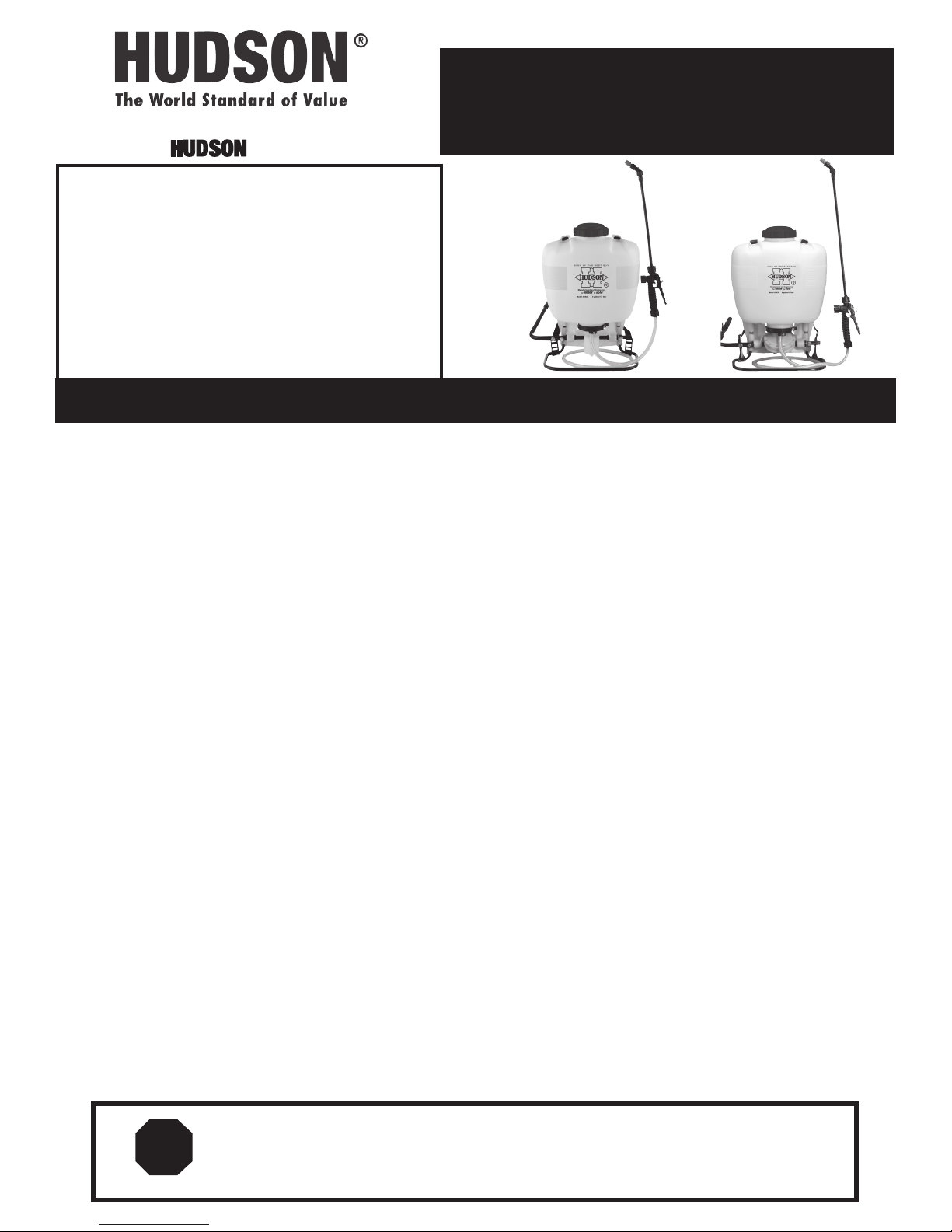
MODEL 93425 and 93475
IF YOU HAVE ANY QUESTIONS OR CONCERNS, OR ARE
MISSING PARTS, DO NOT RETURN SPRAYER TO THE STORE!
93425
Piston
93475
Diaphragm
PLEASE CALL OUR CONSUMER
HOTLINE AT 1-800-9-SPRAYER
(1-800-977-7293)
Visit us on the Internet: www.hdhudson.com
E-mail: ladybug@hdhudson.com
Instruction 871-931 Model 93425 and 93475
maintenance tip: Cap gasket is prelubricated for improved sealing.Occasional lubrication is recommended.
SAFETY PRECAUTIONS:
1. Before using sprayer with chemicals, fill sprayer with fresh water to assure that you have it properly assembled; pressurize and
practice spraying. Also, check for any leaks at this time. When thoroughly familiar with the sprayer operation, follow normal operating
procedures.
2. Ensure all pressure in the sprayer is relieved by locking the shut-off valve in the open position.
3. Avoid contact with chemicals.
4. Always wear rubber gloves, safety goggles and appropriate protective clothing.
5. Work in a well ventilated area.
6. Individuals should be trained in the proper use of this sprayer, chemical handling procedures, and first aid/emergency
care. Where training is not available, individuals should study and follow the procedures detailed in this manual.
WARNING:
Chemicals can be harmful to individuals and the environment if improperly used. In addition, some chemicals are caustic, corrosive or
poisonous and should be avoided. Read warnings and chemical manufacturers’ instructions. Hudson high density polyethylene sprayers
are fitted with Viton
exercised to ensure that sprayer components are clean, functioning properly, and in a good state of repair before and during use. If
in doubt about a particular chemical, check with the manufacturer. If you suspect or observe indications that the material may be
unsafe in a Hudson sprayer...STOP. DO NOT USE OR APPLY CHEMICAL. ALWAYS WEAR RUBBER GLOVES, GOGGLES, AND APPROPRIATE PROTECTIVE
CLOTHING!
Read and follow operating instructions.•
Do not fill with, use, or spray flammable materials.•
Do not modify sprayer.•
Never spray in the direction of humans, animals or property which might be injured or damaged by spray formula.•
Do not use disinfectants, solvents or impregnating agents unless first tested to ensure they are not harmful to the environment or •
sprayer.
Do not use liquids with a temperature above 110°F (43°C).•
Wear appropriate protective clothing to prevent contact with chemical agents.•
Rinse and clean sprayer thoroughly after using. Disposal of contaminated rinse should be in accordance with applicable ordinances. •
Observe the precautionary instructions of the chemical manufacturer.
DO NOT USE ANY ACID (INCLUDING CITRUS) OR CAUSTIC • CHEMICALS (INCLUDING BLEACH).
Remember that a sprayer with liquid is a significant amount of weight (8 lbs. per gallon). Use caution when bending, leaning or •
walking. Bend at the knees rather than the waist.
During sprayer operation, the pressure cylinder (#4400240) contains compressed air and liquid. Compressed air and liquid under •
pressure are inherently dangerous. Before making adjustments on sprayers fitted with a pressure regulating valve body (#4074323)
or control knob (#4074344) located on the pressure cylinder or any other repair or inspection of any sprayer, be sure to relieve
pressure through the shut-off valve and wand.
® seals which are resistant to a wide variety of agricultural and household chemicals; however, care should be
STOP!
If you are missing parts, instructions or have questions, DO NOT take this unit back to the store.
Call 1-800-9SPRAYER. Hudson will send the missing parts/information to you promptly.
Page 2
A
B
D
1. Nozzle
2. Retaining Nut
3. Nozzle Body
Screw Cap
➔
➔
Wand
C
F
F
4. Filter with Gasket
5. Elbow
Gauge Mount
E
O-Ring
Shut-Off
➔
Install Wand
➔
➔
➔
E
Removing plastic adjustable nozzle
Unscrew the nozzle cap (1) from the nozzle body (3). This
is best accomplished while the retaining nut (2) is fastened
tightly to the elbow (5). Next, unscrew the retaining nut (2).
A
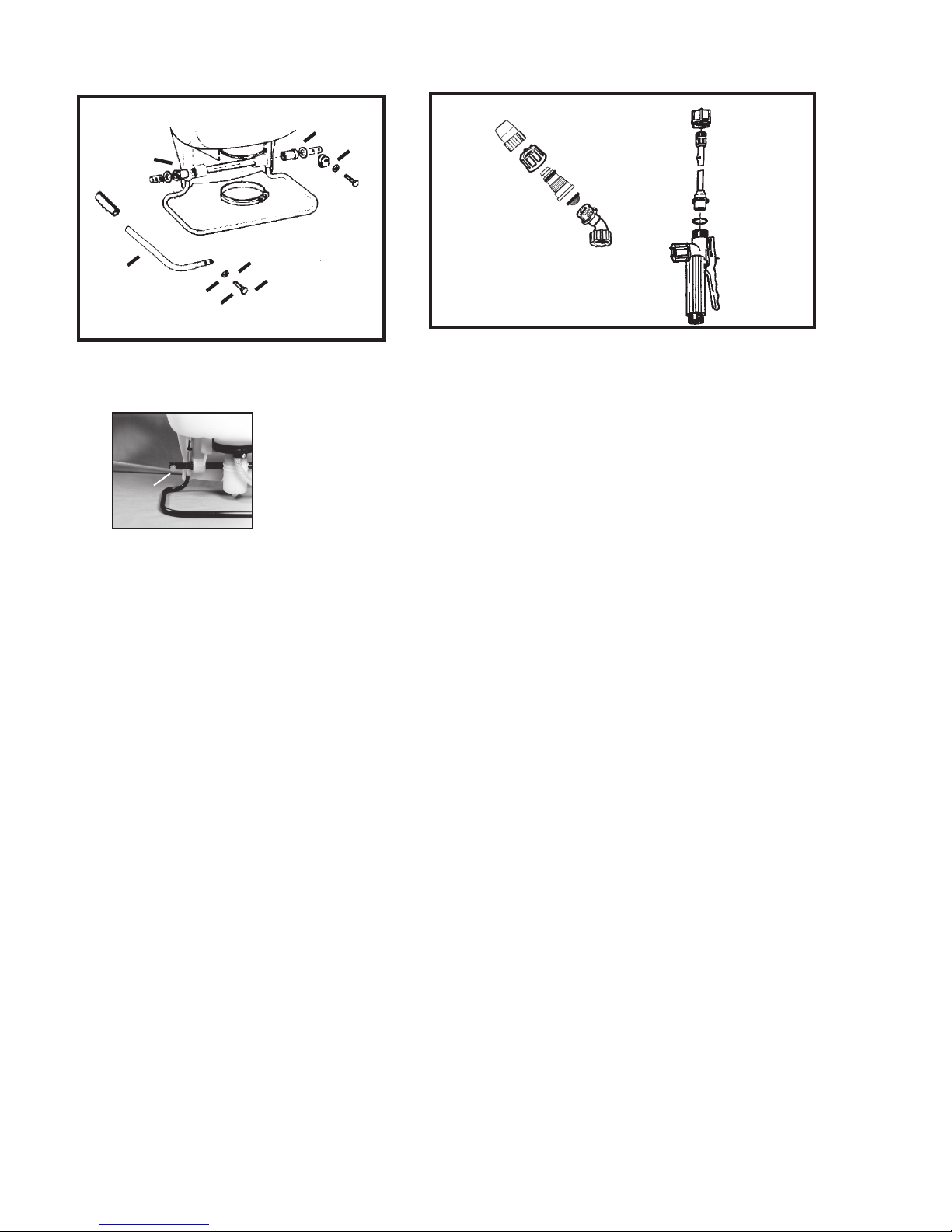
pump leveR installation: All hardware necessary for pump lever installation is
included with the sprayer. The pump lever (C) should be installed as follows: place lever
handle (C) onto the shaft (A). Align bolt holes and install the two bolts (E) and washers
(F); then tighten. To install pump lever on the opposite side, remove the stop plate (D) and
washer, install the pump lever as above. The stop plate (D) should be mounted on the inner bolt hole with the
closed end of the stop plate pointing downward on the opposite side of the pump shaft.
Push the nozzle body (3) out of the retaining nut (2). The filter
with gasket (4) will come out with the body. To reinstall the
nozzle, reverse the above instructions.
assembly instRuctions foR Wand
1. Insert wand into shut-off valve as shown.
2. Tighten the screw cap clockwise onto the shut-off valve.
sHouldeR stRap installation:
The top of the shoulder straps are pre-attached to the sprayer by means of a buckle. The lower end of the straps
are attached by fastening the strap hooks to the metal frame between where frame exits the plastic tank and makes
a bend.
filling:
Mix the spray formula and the proper volume of water in a separate container. Pour the mix through the filter
basket in the tank opening. This keeps debris from entering sprayer. Add 2 or 3 gallons of spray formula mix. Pump
the sprayer handle to prime the pump and fill the pressure cylinder. The volume of liquid in formula mix tank will
appear to decrease as the pressure cylinder is filled. Liquid will flow through the top of the pressure regulator
when the cylinder is completely full. Add the remaining formula mix to the tank. Remember that it’s not necessary
to completely fill the sprayer tank each time. Mix only the amount needed to get the job done.
Always read and follow manufacturer’s instructions printed on the product label. This can save money and help
prevent crop and environmental damage.
2
Page 3
opeRating featuRes:
Nozzles - Your Hudson sprayer is supplied with nozzle arrangements to provide a variety of spray patterns.
Item Application Part #
Flat spray nozzle Row treatment 4074263
Jet stream nozzle Spot & longer range 4074755
Jet stream nozzle and Shrubs and bushes 4074755
Swirl plate = hollow cone 4074756
Plastic adjustable Spot, shrubs & bushes 4900527
nozzle
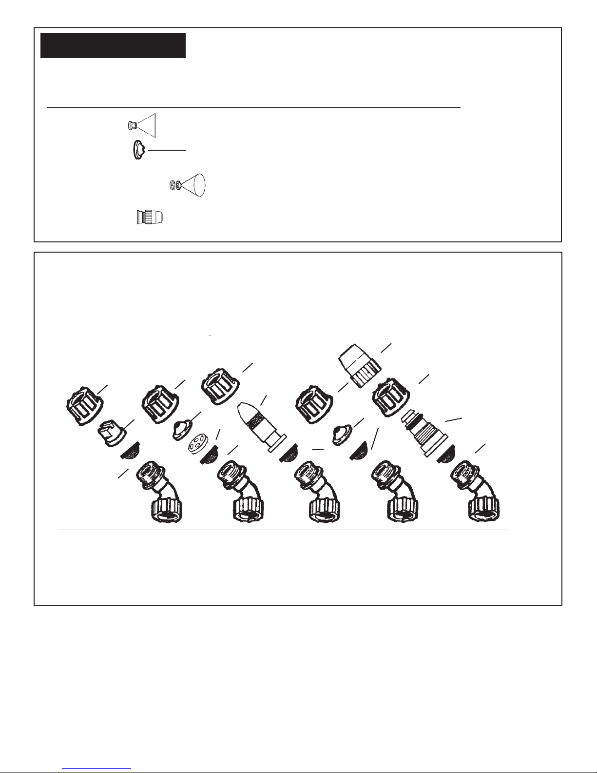
spRay tip assembly
1. Flat spray nozzle
2. Filter
3. Jet cap
4. Swirl plate
5. Nozzle cap
6. Nozzle body
7. Brass adj. nozzle*
8. Nozzle retaining nut
8
1
8
8
7*
3
4
2
8
2
5
8
3
2
6
2
2
Flat spray Hollow
*Brass adjustable nozzle is not a standard item on all Hudson sprayers.
Spray tips should be assembled as above for desired spray pattern.
spRaying:
Prime the pump with rapid pump strokes. When you feel very firm resistance, the pressure chamber is filling with liquid.
With repeated piston strokes, the air in the pressure chamber is slowly compressed. By pressing the hand lever, the valve
opens, and liquid is forced through the nozzle. The shut-off valve has a retaining clip which keeps the valve in the “OPEN”
position for continuous operation. Pump using the end of the pump handle, as it is less fatiguing. The volume of liquid
delivered varies with the working pressure which should be as high as needed to ensure an adequate spray pattern for each individual
application.
NOTE: Should the pressure drop very quickly, drain the tank completely and pump without liquid. By this procedure, the air chamber is
refilled with the required volume of air. It is advisable to pump the tank completely empty from time to time.
cone spray
3
Brass
adjustable
nozzle*
Jet stream Plastic
adjustable
nozzle
Page 4

Wettable poWdeRs:
Avoid use in piston pump sprayer model 93425! The
Hudson model 93475 sprayer with a diaphragm pump
are generally resistant to abrasive materials and are
recommended for this purpose. Note: If you use a wettable
powder in your 93425 sprayer, be sure it is thoroughly
mixed in the formula solution. Immediately after use, be
sure to remove the piston, clean and lubricate the Viton®
collar with petroleum jelly. Thorough flushing of sprayer
will extend the life of its working parts. If you use wettable
powders in the piston pump sprayer, be sure to inspect
regularly for seepage around the piston and repair
accordingly.
cleaning:
• After spraying, clean the tank thoroughly. If some
spray liquid is left inside, drain tank completely.
• Pumpingcausesairtobetakeninandtheremaining
liquid to be discharged. Pump until liquid and air are
coming out through the nozzle.
• Refilltankwithafewquartsofcleanwaterandpump
the water out as explained above (if necessary,
repeat this procedure several times).
• If the shut-off valve is removed, the pump can be
flushed quickly. Improper spray distribution is the
result of a clogged nozzle, which is easily removed
and cleaned.
• Soapandwatermayalsobeusedtocleantank.
• Do not use aggressive cleaning agents or
abrasives.
• Follow the recommendations of the chemical
manufacturer for disposal of waste water and
chemicals.
• Activated charcoal in liquid or other form may be
used to absorb chemicals in tanks or spills.
NOTE: When cleaning the sprayer after working with
hormone weedkillers, follow the instructions of the
herbicide producers. Neutralize with activated
charcoal. (Example: add 0.35 oz./1 g. of activated
charcoal to 1.7 pint/1 liter of water and leave this
detergent in the tank and the lines approximately
for 24 hours.) This is very important if other
chemicals should be sprayed as the residues of the
herbicide may damage susceptible plants. Cleaning after
application of products containing carbolineum, if they
are not water soluble, should be done with a 5% soda lye
having a temperature of 104°F (40°C). Rinse with plenty
of clean water.
maintenance and stoRage tips:
To protect the piston, cylinder and Viton® collar, a fine
mesh, stainless steel screen is located on the pressure
cylinder inlet.
If you find that your sprayer
will not empty the formula
tank, check for a clogged inlet
screen (2). The inlet screen is
located at the bottom of the
pressure cylinder on the side
that faces your back.
One indication that it needs
cleaning is that when you let
go of the pump handle, it
“springs” to the down position.
The screen can be cleaned
with a small bristle brush or
a discarded toothbrush. See
diagram for location of
screen.
• After operation, the sprayer should be storedaway
from direct sunlight to prevent UV damage.
• After removing the pump or when mounting a new
Viton® collar, treat both the collar and the piston with
water-resistant grease.*
• Before winter,drain all liquid in tank, lines and air
chamber. (See “Cleaning.”) Leave shut-off valve
locked in the “open” position.
• Forservice,visitourwebsitewww.hdhudson.comto
locate your nearest Hudson dealer. Always insist on
original Hudson spare parts.
• Regularly inspect hose, wand, pump, tank and
shut-off valve for wear, damage or leaks. Repair
promptly.
• Occasionallylubricatecapgasket.*
Avoid excessive wear by:
1) Regular lubrication of Viton® collar, cylinder and
piston with water resistant grease.*
2) Prompt and thorough cleaning and flushing of
sprayer. Soap and water work well.
1. Pressure Cylinder
2. Inlet Screen
3. Cylinder Support
1
2
3
WARNING!!! THIS PRODUCT IS DESIGNED TO APPLY CHEMICALS THAT MAY BE HARMFUL AND COULD
CAUSE SERIOUS PERSONAL INJURY IF INHALED OR BROUGHT INTO CONTACT WITH THE USER. FAILURE TO
READ AND FOLLOW OWNER’S MANUAL INSTRUCTIONS BEFORE USE AND/OR MISUSE OF THIS PRODUCT
COULD RESULT IN EXPLOSIVE FAILURE WITH MAJOR INJURIES.
WARNING!
4
Page 5

LIMITED WARRANTY
H. D. Hudson Manufacturing Company warrants to the original purchaser only that this product will continue to
function as intended if used in accordance with operating instructions (under NORMAL CONSUMER USE) for
one year. If the product fails to function as intended—DO NOT RETURN IT TO THE STORE—call our CONSUMER
SERVICE HOTLINE AT 1-800-9-SPRAYER (toll free) for fast service. We will, at our option, repair or replace any
non-functioning parts without charge (shipping and handling charges will apply) H. D. Hudson Manufacturing
Company shall have the option of requiring the return of the non-functioning product to the address listed below,
together with the proof of purchase, to establish a claim under this warranty. This warranty does not apply to
damage resulting from accident, misuse, neglect, alterations, operation not in accordance with instructions,
commercial use, or normal wear.
ANY IMPLIED WARRANTIES, INCLUDING THE IMPLIED WARRANTY OF MERCHANTABILITY AND FITNESS FOR
CONSUMER USE, ARE LIMITED TO THE DURATION SPECIFIED ABOVE. H. D. HUDSON MANUFACTURING
COMPANY’S LIABILITY IS LIMITED SOLELY TO THE REPAIR OR REPLACEMENT OF THE NON-FUNCTIONING
PRODUCT OR PART. H. D. HUDSON MANUFACTURING COMPANY EXCLUDES LIABILITY UNDER THIS WARRANTY
FOR ANY AND ALL INCIDENTAL AND CONSEQUENTIAL LOSS OR DAMAGE.
Some states do not allow limitations on how long an implied warranty lasts, or the exclusion or limitation of
incidental or consequential damages, so these limitations or exclusions may not apply to you. This warranty
gives you specific legal rights and you may have other rights which vary from state to state.
IF YOU HAVE QUESTIONS OR CONCERNS: PLEASE CALL OUR CONSUMER HOTLINE AT 1-800-9-SPRAYER.
(1-800-977-7293)
genuine seRvice paRts:
Order them from your dealer or call 1-800-9-SPRAYER (1-800-977-7293).
A
A. 0610402K Shut-off valve repair kit
Includes O-rings, plunger, spring and retaining cap
B. 4900170N 28" universal wand assembly
Includes 28” unbreakable poly wand for hard-to-reach places, adjustable and flat fan nozzle
for multiple spraying tasks, professional shut-off valve with lock-on/lock-off features.
C. 0610408P Sprayer elbow & nozzle assortment
Includes elbow, retaining nut, swirl plate, jet cap, filter screen, flat spray nozzles, no-drip
check valve and O-rings.
D. 0610410P Brass adjustable nozzle kit
Includes retaining nut, O-ring, brass nozzle body and nozzle tip
E. 0610406K Diaphragm pump repair kit
Includes replacement diaphragm, pressure cylinder O-ring, valve plates, seal plug with spring,
and O-rings for valve assembly.
F. 0610407K Piston pump repair kit
Includes Viton collar, pressure cylinder O-ring, valve plates, seal plug with spring, and
O-rings for pump cylinder.
B
In the best interest of continued technological progress, we reserve the right to change design and configuration of
any product without prior or other notice. Therefore, please note that text and illustrations of this manual are not to
be considered binding and do not constitute a basis for legal or other claims.
C D E F
5
Page 6

spaRe paRts list
38
107
108
Deluxe models only
109
110
113
ECS Model
DLX
Only
PLEASE NOTE THAT REPLACEMENT PARTS ARE SOLD AS KITS AND NOT INDIVIDUALLY.
(SEE PAGE 5 FOR KIT LISTINGS) PLEASE CALL OUR CUSTOMER CARE LINE AT 1-800-9SPRAYER.
6
Page 7

INSTALLATION INSTRUCTIONS
PISTON PUMP REPAIR KIT ( # 0610407-K)
Tools needed for kit installation: 6mm Allen Head Wrench, Flat Screwdriver, 11mm Wrench or Cresent Wrench, Long Nose
Pliers, Hammer, 13mm Socket or Wrench, T-25 Torx Screwdriver, Grease or Petroleum Jelly, 2X4 Piece of wood 18” long
1. Using a 13mm socket wrench
remove the handle bolts, and set
aside. Lay unit on its back with pump
assembly facing you. See figure 1.
Loosen hose clamp (E). Pull off sprayer
hose. Caution: There may be liquid
inside the hose and pressure cylinder
even when the tank is empty. Wear
protective gloves. Next, remove the
nut and bolt from protective cap, and
remove cap (C). Loosen stop plate (A)
but do not remove. Rotate the pump
shaft to access the two lever bolts in
the center (B). Using a 6mm allen head
wrench, remove them. Pull the piston
(F) out of the piston cylinder (D).
2. To remove the piston cylinder
assembly, turn the cylinder counter
clockwise when viewing from the
bottom. Figure 2. Caution: The piston
cylinder has sharp edges.
3. Check the inside of the piston and
cylinder for scratches. If the piston or
cylinder are scratched, replace. Figure
3.
4. To remove connecting rods from
the piston and lever, insert a flat
tip screwdriver between the two
connecting rods and twist. Figure 4.
5. With the new piston, place the two
connecting rods over the studs on the
inside of the piston. Place the lever
studs into the connecting rods and
snap together with your fingers. Figure
5.
6. To replace the Viton® collar, push
it off the top of the piston with your
thumb. Figure 6. Install the new collar
on the piston onto the form fitted sides.
C
E
D
Figure 1.
Figure 2.
Figure 3.
Figure 4.
Figure 5.
B
A
8. If necessary remove the pressure
cylinder by unscrewing the pressure
F
regulator control, if equipped. Remove
the large clamp at the bottom of the
cylinder. Use a block of wood and hit
forcefully with a hammer, driving the
assembly through the bottom of the
tank. Figure 9.
9. Next, assemble the piston cylinder.
First grease the O-ring on the piston
cylinder, being careful not to get any
on the valve plate, and then place
the piston cylinder into the pressure
cylinder. Screw the piston cylinder
clockwise until it is tight and the
bottom O-ring is no longer seen. Figure
10. When properly seated the notch on
the piston cylinder (G) will line up with
the indent on the pressure cylinder (H).
Figure 11.
10. Apply a light coat of grease to the
inside of the piston cylinder wall and
on the Viton® collar, and then re-install
the piston into the piston cylinder.
Figure 12. To insert the piston, tilt at
a slight angle with the leading edge
of the Viton® collar placed over the
slot. When seated, install the 6mm
Allen Head bolts through lever base
into shaft. Replace the protective cap
and tighten the nut and bolt. Reinstall
the handle. Re-tighten the stop plate,
making sure the bolt goes through the
rear hole. Replace the hose and black
hose clamp making sure it is firmly
secured. Re-tighten the stop plate,
making sure the bolt goes through the
rear hole. Replace the hose and black
hose clamp making sure it is firmly
secured.
Figure 8.
Figure 9.
Figure 10.
G
Figure 11.
Figure 12.
H
7. Remove the valve plate and
O-rings from the outside of the piston
cylinder. Install the new valve plate
and the two O-rings making sure the
O-rings seat in the grooves. Finally,
inside the piston cylinder you will find
a second valve plate. Using needle
nose pliers, pull out the red or orange
pin and remove the valve plate. Figure
7. Install a new valve plate and firmly
reseat the retaining pin using needle
nose pliers. Figure 8.
Figure 6.
Figure 7.
NOTE: Always wear rubber gloves, safety goggles and appropriate
protective clothing when repairing a sprayer. Work in a well-ventilated
area. Prior to repair, flush unit with water by filling, then spraying the
water into an appropriate container or area. Ensure that all pressure is
released by locking the shut-off valve in the open position. Once a repair is
completed, fill the unit with clean water, pressurize, and check for leaks. If
the sprayer leaks, DO NOT USE. Repair leaks and recheck.
7
Page 8

INSTALLATION INSTRUCTIONS
Diaphragm Pump Repair Kit ( # 0610406-K)
Tools needed for kit installation: 6mm Allen Head Wrench, Flat Screwdriver, 11mm Wrench or Cresent Wrench, Long Nose
Pliers, Hammer, 13mm Socket or Wrench, T-25 Torx Screwdriver, Grease or Petroleum Jelly, 2X4 Piece of wood 18” long
1. Using a 13mm socket wrench,
remove handle bolts and loosen the
stop plate (A) and remove the two
allen head screws (B) that hold the
connecting pieces to the pump rod.
Figure 1.
2. With unit laying on its back with
pump assembly facing you, remove the
pump rod (C). Loosen hose clamp and
remove pressure hose (D). Next, loosen
the clamp at the base of the sprayer (E).
Figure 2.
3. Push the pressure cylinder
approximately 1" out of the bottom of
the tank. Then turn the pump assy. 180
degrees. Note: Wooden block may be
used to tap the pump assembly through
bottom of tank. Remove pressure
regulating valve, if equipped before
removal of cylinder.
4. Next remove the 12 torx screws that
hold the flange in place. The flange
and diaphragm can then be removed.
Figure 3. Note: For clarity the pressure
cylinder is shown removed from the
tank.
5. To replace the diaphragm, remove
the connecting rod retaining screw (G)
from the plunger and lever (F). Replace
the diaphragm and reassemble. See
Figure 4.
6. The valve assy. (H) is removed using
a locally made tool. Remove red valve
plate retaining pin using needle nose
pliers, then insert tool into slots. See
Figure 5. Use a screwdriver to rotate
tool counter clockwise.
7. Once the valve assembly is removed,
the valve plates and O-rings can be
replaced. The bottom valve plate is
secured into place with a red retaining
pin. Push pin into place using needle
nose pliers. Figure 6.
8. The pump housing (I) is separated
from the pressure cylinder (J) by pulling
it off. Figure 7. The O-ring can then be
replaced.
Figure 1
Figure 2
Figure 3
G
Figure 4
Figure 5
Figure 6
J
Figure 7
9. When reassembling the pump housing
to the pressure cylinder, be sure the
square tab on the pump housing (K) is
K
L
aligned in the notch. See arrows (L)
on the pressure cylinder in Figure 8. Be
careful not to pinch or nick the O-ring.
Note: Grease O-rings for re-assembly. Screw
Figure 8
the valve assembly into the cylinder.
10. Place diaphragm assembly (O) onto
the pump housing (M). Place the flange
(N) over the diaphragm. Reinstall the 12
M
N
O
torx screws around the outside diameter
of the flange. Figure 9.
11. Push pressure cylinder into the
Figure 9
tank being careful not to pinch the large
O-ring (P).
Note: Wooden block may also be used
for installation of the pressure cylinder.
P
12. Tighten pump clamp securely
F
(E). Install pump rod (C). Reinstall the
connecting pieces and allen head screws
Figure 10
(B). Reinstall the stop plate (A) making
sure that the bolt goes through the rear
hole. Reinstall the hose and hose clamp
making sure it is firmly secured (D).
H
Figure 11
I
NOTE: Always wear rubber gloves, safety goggles and appropriate
protective clothing when repairing a sprayer. Work in a well-ventilated
area. Prior to repair, flush unit with water by filling, then spraying the
water into an appropriate container or area. Ensure that all pressure is
released by locking the shut-off valve in the open position. Once a repair is
completed, fill the unit with clean water, pressurize, and check for leaks. If
the sprayer leaks, DO NOT USE. Repair leaks and recheck.
8
 Loading...