

Page 1
Page 2
This manual provided by
HET Club member
Drew Meyer
Page 3

I
FOREWORD
ORGANIZATION
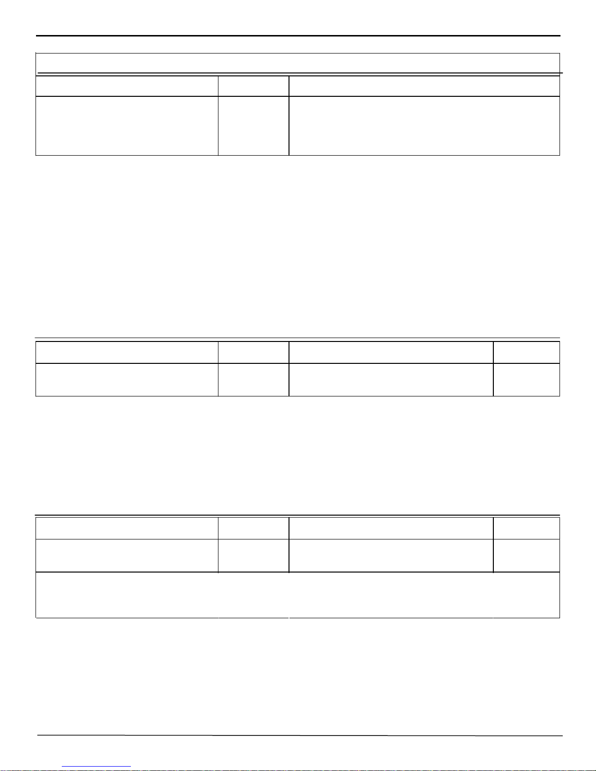
Much has been written and spoken about the proper operation of a service department and the factors
which make such an operation profitable and successful.
Some of these operating factors, tried and proven by successful dealers, will bear repetition frequently.
We all know them but are prone to overlook and even disregard them unless they are occasionally called to our
attention.
Some of the more important factors are:
1. Shop Appearance
2. Proper Service Equipment
3. Personnel - Proper dress
Neat appearance
APPEARANCE IS IMPORTANT
Customers are inclined to judge the quality of your work by the appearance of your shop. In looking over
your operation from an appearance standpoint, the first thing to check is identification. The Hudson Service
sign is designed to identify your place of business as an authorized Hudson service station and will not only
create confidence in the minds of the owners but will guide transient owners and new customers to your door.
Next in order is an inspection of the service department and shop. Is it as clean and attractive as soap and
water and paint can make it? Hot water, cleaning compound, and a few gallons of paint will work wonders in
the appearance of a service department and will return their cost many times in increased customer satisfaction
and comfort.
An accumulation of junk and broken and discarded parts and tools is an eyesore in any shop. An easily
accessable junk box outside the building, near an alley for easy unloading, is the best answer. Make each
member of the service staff responsible for removing his own junk parts. Remember - - - - - - first impressions
are lasting.
EQUIPMENT
Adequate equipment provides the means for good service men to perform first class service work at a
minimum of cost. Car owners, thru costly experience with poorly equipped shops, have become tool and
equipment conscious. Therefore, proper tools and equipment are a strict necessity. We must show our
customers that we have the equipment by proper arrangement and display.
Page 4

II
INTRODUCTION
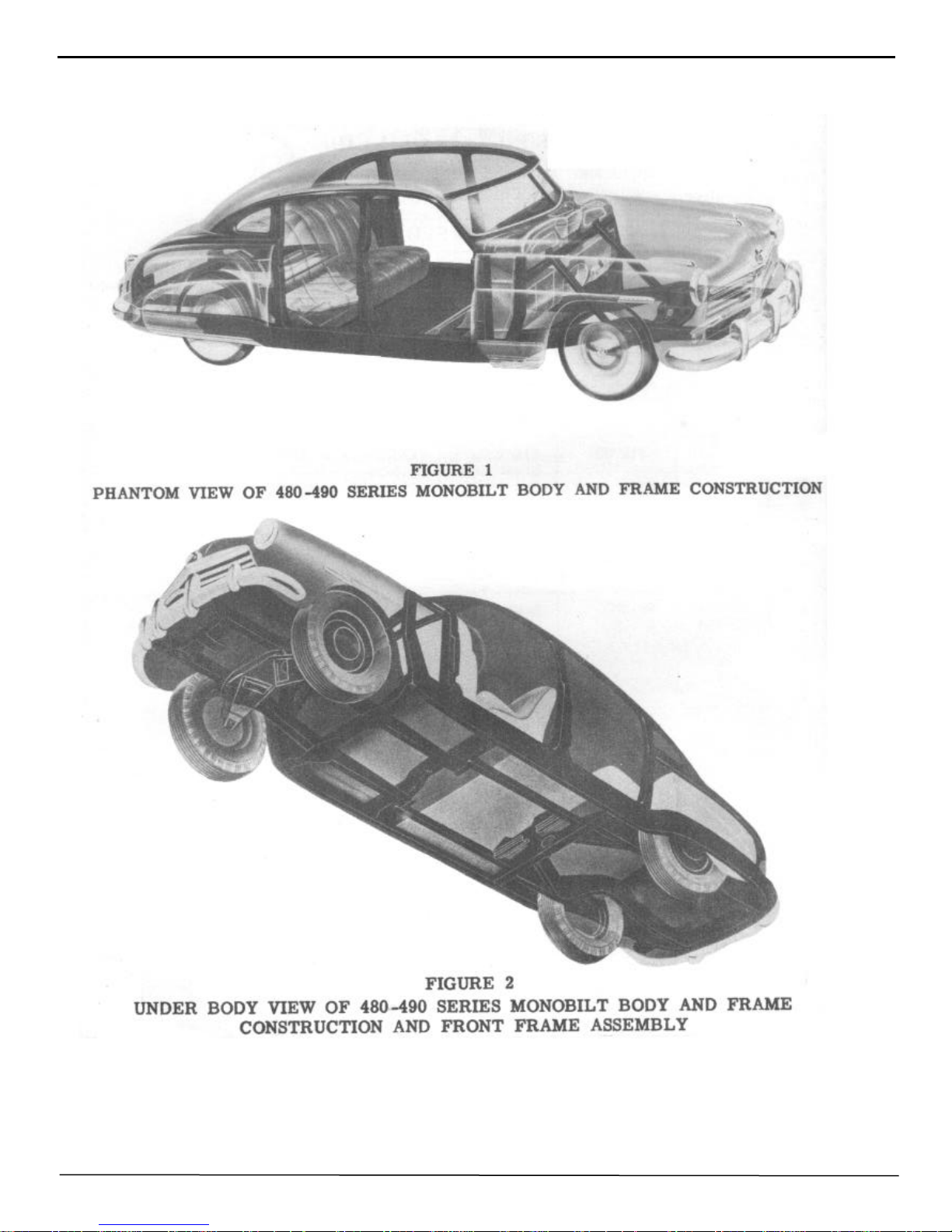
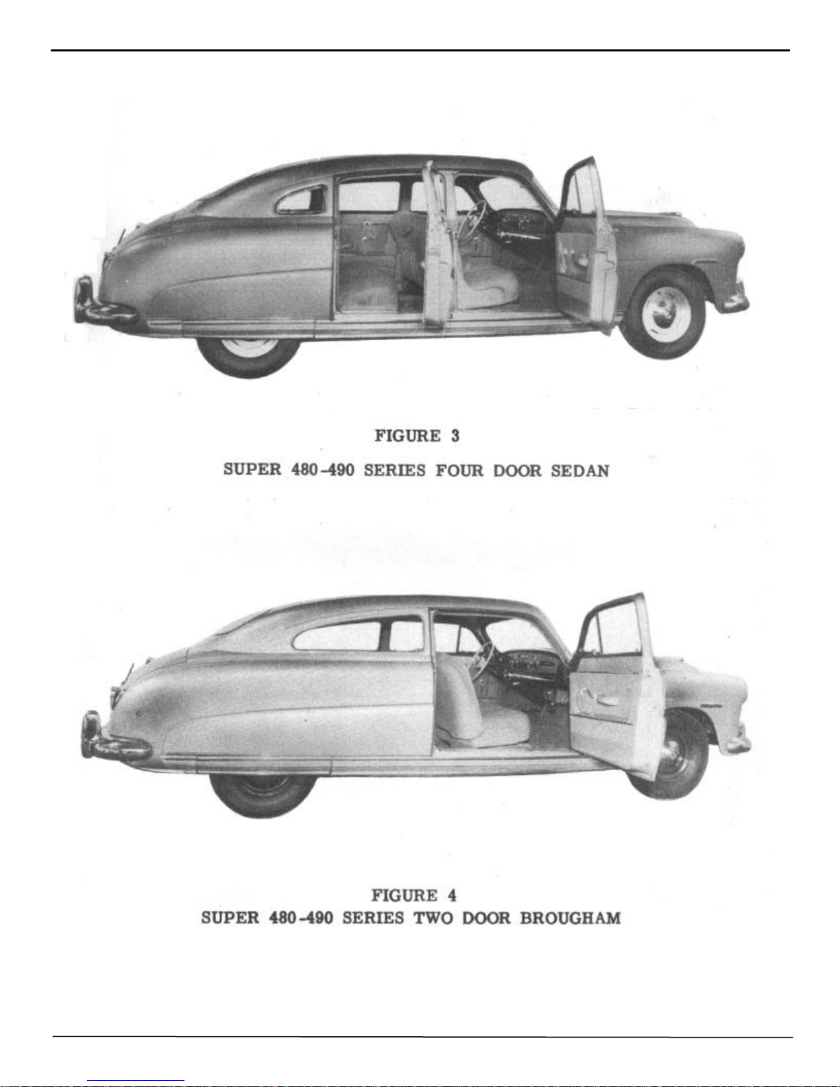
The series 480 and 490 Hudson is built of a completely new principal and design, and is not just another
motor car. The "Monobilt" body and frame construction differs greatly from the conventional motor car
employing separate body and frame units. Naturally being so totally different, a new approach to the repair of
body damage is necessary. These differences, however, do not make the repair job more difficult or more
costly to complete. In many instances the time required on a specific operation is less than that required on
previous models.
Once you are completely familiar with the Monobilt body and frame construction of the 480 and 490
series Hudson, when you have learned the placement of all of the various parts and assemblies and how they
fit together to make the rugged and sturdy Monobuilt all steel unit, then you will go about each job with
complete confidence.
The information contained in this body manual is to be used as a guide for servicing the 480-490 series
Hudson.
The manual has been divided into four parts:
Part one - includes technical information, model designations, body paint color code, estimating and
ordering of repair parts, car serial number identification, and trim material color chart. Illustrated in this
section are the various body types, positions of body welds and top panel soldering.
Part two - includes removal and installation of sheet metal parts: viz., fenders, rocker panels, hood, grille,
rear compartment; also interior hardware, trim, instruments, headlining, door locks, handles, and regulators;
and front wheel alignment.
Part three - includes body repair and metal finishing, consisting of tool application, bumping, dinging,
solder filling, shrinking, fender welding, filing, sanding, and removing minor dents. Part three also includes
body alignment checking, door repairs, and door alignment.
Part four - comprises the convertible 480-490 series, consisting of complete information on repairs of
hydraulic and electrical units, removal and installation of component assemblies and parts, top adjustments,
and trouble shooting.
Illustrations and pages of this manual are numbered consecutively.
An alphabetical index is placed in the front of the manual for easy reference.
A thorough study of the operations and necessary tools and equipment will enable the Hudson Service
dealer to perform reliable service at reasonable cost.
Page 5

INDEX
III
Adjustment, door striker
folding top
hood
radio
weather control
door window
windshield wiper arms
top control rod
Alignment, body
door
frame
front wheel
rear curtain, convertible
Battery gravity
Bleeding the hydraulic system
Body aligning
Body repair
Breaker, circuit
Brazing
Bumping
Camber
Caster
Cigar lighter
Circuit breaker
Circuit breaker- check, convertible
Cleaning upholstery
Clock
Coil spring sag
Cold shrinking
Construction, body
Color guide
Colors, body
Convertible brougham
Curtain, rear
Cylinder, door lock
Cylinder, hydraulic
Cylinder, solenoid
Dimensions
Dinging
Door aligning
Door lock cylinder
glass front
glass rear
lock
outside handle
remote control
striker plate adjustment
striker plate
trim panel
ventilator wing
ventilator wing regulator
window regulator front
window regulator rear
Page
27,60
74
23
38
40
88
36
74
48,62-64
58
60-61
1,41-43
85
90
94
62
47
32,41,88,91
54
47-54
1,41-43
1,41-42
33
32,41,88,91
91
44
34
43
53,55
50
9,25
3-5
13,67-96
84-86
27,83
69,74-78
77,92-93
2
52,53
58
27,83
31,77
31,77
27,29,83
28-82
30,83
27-60
27
28,31,81,82
30,78
30
28
29
Door lock lubrication
Door straightening
Door trim panel - Convertible .
Door window regulator hydraulic
convertible
cylinder
Elastic metal
Electrical system checks - convertible
Fender, front
rear
Fender and grille side support
Fender stone guard and panel - front
Fender tie panel
Filing
Finish, care of
Fluid, hydraulic
Fluid pressure
Flux
Forging welds
Frame alignment
Front suspension
Fuel gauge
Fuses
Glass, door
quarter window
rear window
windshield
Grille, radiator
radio speaker
Ground, cylinder solenoid . . .
pump motor
Gauge, fuel
rear curtain
temperature
Handle, door
Headlining
Heat shrinking
Hood
Hood adjustment
lock upper support
lock lower support
Hydraulic pump prime
Hydraulic system check - convertible
Hydro-Lectric Motor and pump assy
Hydro-Lectric, service
system
Ignition switch
Instruments
Instrument panel
Insulation
Jacks, body
Lamps
Lock, door
Page
83
59
81
75-77
77
77
47
91
20
19
23
20
24
52,53,57
45
76,90-91, 94
70,76,93
54
57
60
1,41-43
35
41
31,77
31,32
32
26
22
37
77,93
70,71,72
35
85
35
28,82
24-27
53,55
23
23
23
23
94
93
70,72
90
67-96
32
32
32
65
49,51-52
2,33,34
27,29,83
Page 6

Window operating switches-convertible
IV
Lubrication, body
hydraulic cylinder
lock
Metal finishing
Model designations
Monobuilt body
Motor, pump
Motor solenoid switch check-convertible
Normalizing
Paddle, solder
Paint
Paint - care of finish
Panel, instrument
switch
trim
Parts, repair
Pivot pin inclination
Pulley adjustment
Pump hydraulic
Quarter trim panel
Quarter window
trim panel
window regulator
Quarter window - convertible
Quenching
Radiator
Radiator grille baffle (upper) .
front splash guard and moulding
grille center bar (upper)
Radiator splash guard moulding
Radiator "U" channel
Radio
Radio - installation
automatic tuning
Rear window
Refilling the hydraulic system convertible
Remote control, door
Regulator, door wing
front door
hydraulic
quarter window
rear door
Resealing
Reservoir, fluid
Rheostat, lamp
Riding height and coil spring sag
Roof bows
Roughing
Sanding
Sealing
Seat cushion front and rear
back, front and rear
Serial numbers
Shrinking - cold
hot
Solder filling
Speedometer
Page
16
75, 77
83
47-58
1
II, 10
68, 69,70-72, 90
92
64
9, 54
3-6,45
45
32,34,37
34
28,31,81,82
6, 19
42
36
70,72,90,94
82
31
31
32, 79
79
54,56
22
22
22
22
23
22
36, 39
36
38
32
94
30, 83
30, 78
28
69,75-78,86,88
32,79
29
64
70,71,90-91
33
43
9, 25
48, 58
53,58
65
82
82
1,6
55
55
52,53,54
34
Spindle pin inclination
Splash guard
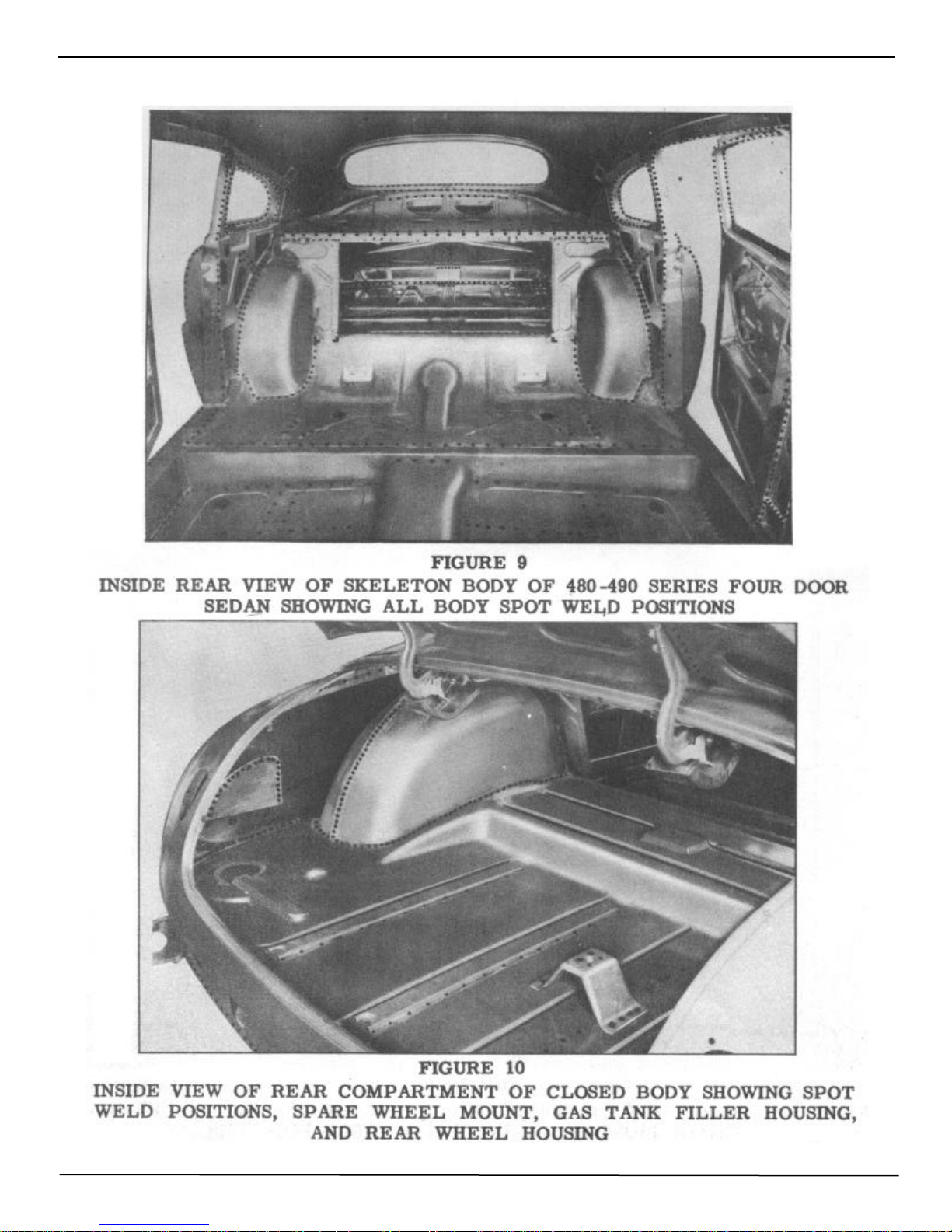
Spot weld positions
Springs, front
rear
window regulator
Starter switch
Stone guard
Striker, door
Switch, ignition
light
motor solenoid
starter
top operating
window operating
Technical Information
Temperature gauge
Tie rods
Tools - application of
Tools - body
clip removing
headlining
switch removing
Toe-in
Toe-out
Top adjustment
Top control rod
Top covering installation
Top, folding
Top operating cylinder
Top operating switch check
Top operating valve and switch
Torch soldering
Tramming
Trim material
Trim panels
Trouble shooting
Upholstery cleaning
Upholstery material
Valve, cylinder solenoid
pressure relief
top operating
Weather control
Wedge, hydraulic
Welding
Wheel bearings
Window adjustment
Window lift switch-check-convertible
Window regulator solenoid check
Windshield
Windshield wiper
Windshield wiper control
wiper cable tension
Wing, door ventilator
Wiring
Page
1, 41-42
22, 23
13-15
2 43
2
69, 75, 76
32
20
27, 60
32
32
68, 69, 70, 92
32
72, 73, 90, 91-92
69, 79-81, 88, 91
1
35
1
50
49
78
25
80, 81, 91
1, 41, 43
43
86 87
73, 74, 91
84
68, 70-75, 84, 16
74, 75
91
72, 73, 74, 93
52, 53, 54
62
7
28, 31, 81, 82
95-96
44
7
77, 92-93
70 93
68, 72, 73, 90, 93
39, 41
49
53, 54, 57
1
88 89
91
79, 80
92
26
33
33
36
30, 79
88, 89, 90, 91, 93
Page 7

BODY MANUAL 1
NOTE: Caster must not vary
more than ½ between sides
Tie Rod End Adjustment (As
seen from right side of car
):
MODEL DESIGNATIONS AND SERIAL NUMBERS
The new Hudson models are produced in the Super and Commodore Series and carry the following designations:
Hudson Super Six Series - Model 481 - 491
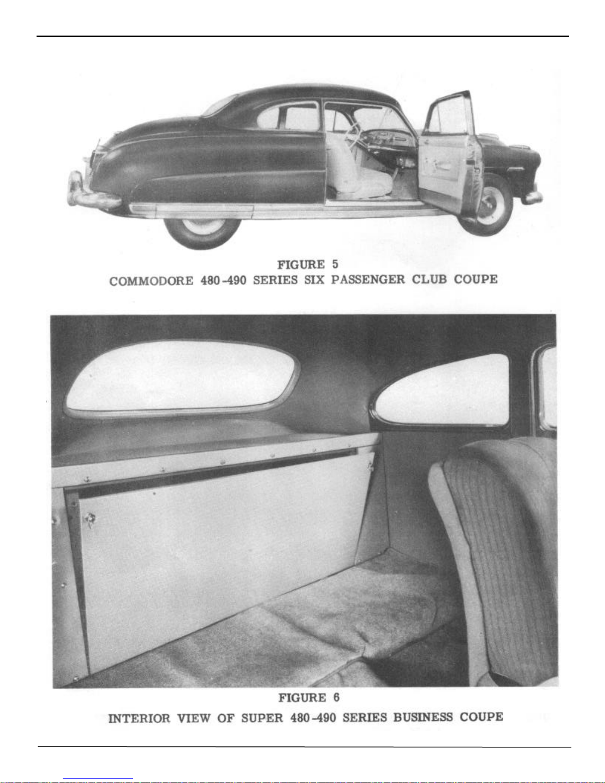
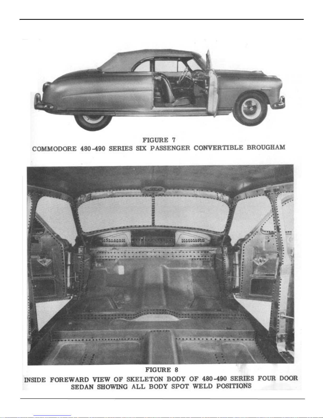
BODY TYPES
Brougham
4 Door Sedan
3 Passenger Coupe
Club Coupe
Convertible Brougham
4 Door Sedan
Club Coupe
4 Door Sedan
Club Coupe
4 Door Sedan
Club Coupe
Convertible Brougham
STARTING SERIAL NO’S
481101 - 491101 and up
Hudson Commodore Six Series - Model 482 - 492
482101 - 492101 and up
Hudson Super Eight Series - Model 483 - 493
483101 - 493101 and up
Hudson Commodore Eight Series - Model 484 - 494
484101 - 494101 and up
The car serial number, which is also the engine number, is stamped on a metal plate attached to the right front
door hinge pillar post. In the car numbering system, the first three digits of the serial number indicate the series and
model while the remaining digits represent the actual car number. As the cars leave the production line, they are
numbered in consecutive order, regardless of series or model. As an example, the car built after serial number
491999 would be numbered 4911000 instead of 492000. Code letters or numbers indicating the car paint color
option are stamped on the upper hinge of the right front door.
TECHNICAL INFORMATION
FRONT SUSPENSION SIX CYLINDER EIGHT CYLINDER
Type
Camber
Caster
Toe-in
Spindle pin inclination
Spindle pin thrust bearing
Wheel Bearing - Type
End Play
Tie Rod End (Type)
Number of Tie Rods
Independent Coil Springing
1/2° to 1-1/2°
1/2º to 1-1/2°
0" to 1/16"
3° - 36'
Ball
Adjustable tapered roller
.001 to .003
Plain Bearing
2
Independent Coil Springing
1/2º to 1-1/2º
1/2º to 1-1/2 ° sides
0" to 1/16"
3° - 36'
Ball
Adjustable tapered roller
.001 to .003
Plain Bearing
2
To lengthen
To shorten
Turn clockwise
Turn counter-clockwise
Turn clockwise
Turn counter-clockwise
Page 8

2 BODY MANUAL
FRONT SPRINGS SIX CYLINDER EIGHT CYLINDER
Type
Free Height
Height under curb weight
REAR SPRINGS
Type
Covers
Length and Width
Number leaves
Shackles
Lubricant-Shackles and Leaves
Headlight (Sealed Beam Type)
Hood Light
Parking Light with Direction
Indicator
Tail and Stop Light
License Light
Dome Light-Front
Rear Quarter Lights (2)
Clock
Speedometer
Instrument Cluster
Direction Indicator
Ignition Lock
Courtesy Lights
Fog Light (Sealed Beam)
Spot Light Sealed Beam)
Parking Light
Generator and Oil Indicator
Radio
Headlight Beam Indicator
Coil
16-5/16"
9-9/16"
Semi-elliptic
Covered
Uncovered
Metal
54" - 1-3/4"
8
Silent "U" Threaded
Viscous chassis lube
LAMP BULBS
No.
4030
55
1154
1154
63
87
81
55
55
55
55
55
87
4015-A
4535
63
55
55
55
C. P.
Sealed
2
21-3
21-3
3
15
6
2
2
2
2
2
15
Sealed
Sealed
3
2
2
2
Coil
16-5/16"
9-9/16"
Semi-elliptic
Covered
Uncovered
Metal
54" - 1-3/4"
8
Silent "U" Threaded
Viscous chassis lube
Base
Sealed
Single
Double
Double
Single
Single
Single
Single
Single
Single
Single
Single
Single
Sealed
Sealed
Single
Single
Single
Single
DIMENSIONS (6 Passenger 4 Door Sedan)
Wheel Base
Overall Length
(Including Bumpers and Guards)
Overall Width (Including Fenders)
Tread
Front
Rear
Road Clearance
Front
Rear
Overall Height-Road to Roof
SIX CYLINDER EIGHT CYLINDER
124"
207-1/2"
77"
58-1/2"
55-1/2"
8"
8"
60"
124"
207-1/2"
77"
58-1/2"
55-1/2"
8"
8"
60"
Page 9
BODY MANUAL 3
1948 HUDSON BODY COLORS
Standard Single Body Colors Option Special Two-Tone Combinations Option
Banner Blue
Jockey Blue
Gallant Gray
Quartermaster Gray
Piedmont Green
Savoy Green
Maroon-Deep
Ruby Red*
Navahoe Bronze
Harness Tan
Ebony Black
* Ruby red is a special body color and is listed above only to complete the two-tone combination
with maroon-deep.
B
M
RR
G
Q
N
H
K
Upper Body Color
J
P
S
Lower Body Color
Upper Body Color
Lower Body Color
Upper Body Color
Lower Body Color
Upper Body Color
Lower Body Color
Upper Body Color
Lower Body Color
SPECIAL SINGLE BODY COLORS
JB
QG
SP
RM
HN
Body Colors Option Option on Models
Ruby Red*
Platinum
RR
CC
481-P - 482 - 483 - 484 Broughams
Sedans, Bus. Coupes, Club Coupes, and
481-P - 482 - 484 Convertible Brougham
ORDERING PAINT OR PAINTED PARTS
When ordering paint or painted parts, special care should be exercised in listing the paint option code and the
paint color or colors. This information is valuable, especially when the automobile has a two-tone color
combination. Always use the charts furnished herein and be sure that every repair order including paints has the
complete, detailed information.
Hudson body colors are pure virgin lacquers. For the maintenance and protection of these high quality finishes
refer to Page 45 of this manual under the heading "Paint - care of finish."
Page 10
4 BODY MANUAL
CHART No. 1
1949 HUDSON BODY COLORS
Standard Single Body Colors Option Special Two-Tone Combinations Option
Brigantine Blue**
Jersey Blue
Glowing Gray
Queenstown Gray
Piedmont Green**
Savoy Green**
Nomad Bronze**
Holster Tan**
Maroon - Deep**
Ruby Red*
Ebony Black
* Ruby red is a special body color and is listed above only to complete the two-tone combination
with maroon-deep.
**Not available on convertible brougham.
M
RR
G
Q
N
H
K
B
J
P
S
Upper Body Color
Lower Body Color
Upper Body Color
Lower Body Color
Upper Body Color
Lower Body Color
Upper Body Color
Lower Body Color
Upper Body Color
Lower Body Color
SPECIAL SINGLE BODY COLORS
Body Colors Option Option on Models
JB**
KG
SP**
HN**
RM**
Ruby Red*
Platinum
*Refer to Page 5 for 1949 body color option information.
RR
CC
491-P - 492 - 493 - 494 Broughams
Sedans, Bus. Coupes, Club Coupes, and
491-P - 492 - 494 Convertible Brougham
CHART No. 2
1949 HUDSON BODY COLORS
Standard Single Body Colors Option Special Two-Tone Combinations Option
Pacemaker Green Opalescent
Sierra Green Opalescent
Naples Tan Opalescent
Hardwood Tan Opalescent
Gull Gray Opalescent
Quebec Gray Opalescent
Burgundy Maroon Opalescent
Radiant Red Opalescent*
Brazilian Blue Opalescent
Jet Blue Opalescent
Ebony Black
8
10
7
3
2
9
6
16
1
4
5
Upper Body Color
Lower Body Color
Upper Body Color
Lower Body Color
Upper Body Color
Lower Body Color
Upper Body Color
Lower Body Color
Upper Body Color
Lower Body Color
14
11
13
15
12
Page 11
SPECIAL SINGLE BODY COLORS
Body Color Option Option on Models
BODY MANUAL 5
Radiant Red Opalescent
Gray Gold (light) Opalescent
16
17
491P - 492 - 493 - 494 Broughams, Sedans,
Bus. Coupes, Club Coupes, and 492-P 492 - 494 Convertible Brougham.
1949 BODY COLOR OPTION INFORMATION
It will be noted that the 490 Series Hudson has two methods of paint option identification. On approximately the first 100,000
490 Series cars an ALPHABETICAL paint option was stamped into the right hand front door upper hinge, body half. (See 1949
Body Color Chart No. 1)
Body color Chart No.2 lists the new body colors and the NUMERICAL options used on the 490 Series Hudson after
approximately the first 100,000 cars. This numerical paint option is also stamped into the body half of the right hand front door
upper hinge.
EXAMPLE: (Chart No. 1)
Single Body Color Option
Brigantine Blue
Jersey Blue
Two-Tone Combination
B
J
Brigantine Blue
Jersey Blue JB
Option
Either brigantine blue or jersey blue may be used as an all over body color in which case a single "B" or "J" will
be stamped into the right hand front door upper hinge. When both brigantine blue and jersey blue are used together as a two-tone combination, the letters "JB" will be stamped into the right hand front door upper hinge.
EXAMPLE: (Chart No. 2)
Single Body Color Option
Pacemaker Green Opalescent
Sierra Green Opalescent
The application of the numerical option colors is handled in the same manner as is the alphabetical
options outlined above.
8
10
Two-Tone Combination
Pacemaker Green Opalescent
Sierra Green Opalescent 14
Option
Page 12

6 BODY MANUAL
jobs, or lose money on them if you do get them. A successful future for your business depends upon the correctness
In the event a new NUMERICAL body color is used in two-tone combination with an old ALPHABETICAL
body color, the option stamping will appear as below:
Brazilian Blue Opalescent (New) 1
Jersey Blue (Old) J
This will be the only occasion when both SINGLE body color options used in two- tone combinations will appear stamped in the right hand front door upper hinge.
ESTIMATING AND ORDERING OF REPAIR PARTS
Like any other automobile repair operation, the damaged body must have a preliminary survey to determine the
over all extent of the damage. When the survey has been completed, the answer to three vital questions will be necessary before work can begin.
Can you repair the damage?
How much will it cost?
How soon can it be ready?
The accuracy of your answers to these vital questions determines whether or not your shop gets the repair job
and whether or not you make any profit on the job if you do get it. Guessing won't do----that way you lose repair
with which you answer those three important questions.
The service departments of all Hudson distributors and dealers are supplied with current service parts catalogues
from which a listing, by PROPER NAME and PART NUMBER, of the parts required can be formulated.
From this list, which includes the proper car IDENTIFICATION NUMBER taken from the car serial number
plate, the Hudson parts manager will be able to arrive at an estimate of the cost of the job, from which a definite decision can be made before ordering the necessary parts.
To be certain that the proper repair parts are received with the least possible delay, it is important that the following car identification be included with each repair order.
CAR SERIAL NUMBER PAINT CODE MARKINGS *
*The paint color code is the alphabetical stamping on the right hand front door upper hinge, body half.
By supplying this information you are enabling those who make up the repair parts order to include the correct
parts. Thus delays, such as would be encountered upon the receipt of the wrong parts, are eliminated, and considerable time is saved.
Page 13
BODY MANUAL 7
DESCRIPTION OF PARTS
The correct description of the parts as they are listed in the service parts catalogue is all-important, as is the location of the part on the automobile.
For example fenders, doors, windshield glass, and rocker panels should be referred to as left or right, front or
rear.
ORDERING TRIM MATERIAL
The following chart on the Hudson upholstery options in relation to paint options will prove helpful when the
need arises to order upholstery material.
The paint option chart is also included and will serve to clarify the alphabetical paint code stamping on the upper
hinge of the right hand front door and as a cross reference guide when ordering upholstery materials. See Page 4.
CHART No. 3
Use This Chart In Conjunction With Chart No. 1, Paint Option Codes
1948 COMMODORE SERIES UPHOLSTERY OPTIONS
Option Model Upholstery Color Standard with Body Colors
W-1
W-2
482-484
482-484
Tan Broadcloth
Gray Broadcloth
H,K,M,N,P,RR,S,HN,SP,RM
B,CC,G,J,K,Q,JB,QG
1949 COMMODORE SERIES - EXCEPT CONVERTIBLES
W-1
W-2
W-3
W-4
492-494
492-494
492-494
492-494
Tan Broadcloth
Gray Broadcloth
Brown Cloth and
Maroon Leather Trim
Gray Cloth and
Maroon Leather Trim
H,M,N,P,RR,S,HN,SP, and RM
B,CC,G,J,K,Q,JB, and QG
(Optional)
(Optional)
CONVERTIBLE BROUGHAM UPHOLSTERY
Models Color
491, 492, 494 Maroon Leather antique grain is standard
Models Color
481, 491, 483, 493 Bedford Cord cloth, Blue-Green shade, is
SUPER SERIES UPHOLSTERY
standard
Page 14
8 BODY MANUAL
CHART No. 4
Use this chart in conjunction with chart No. 2, 1949 "Paint Option Codes"
COMMODORE SERIES - EXCEPT CONVERTIBLES
Option Model Upholstery Color Standard with Body Colors
W-1
W-2
492-494
492-494
Tan Cloth Trim
Gray Cloth Trim
CONVERTIBLE BROUGHAM UPHOLSTERY
Models Models
491-492-494 Maroon full leather trim is standard.
Brown cloth and maroon leather
combination trim - optional.
Gray cloth and maroon leather
combination trim - optional.
SUPER SERIES - EXCEPT CONVERTIBLES
Model Color
491, 492, 494 Gray cloth trim is standard
Gray leather trim - optional
M-6, RM-15, RR-16 and CC-17
H-3, N-7, HN-11, P-8, S-10, SP14
B-1, G-2, J-4, Q-9, JB-12, QG-13
and K-5
LEATHER TRIM
ALL BROUGHAMS, SEDANS, BUSINESS COUPES, AND CLUB COUPES
Material Color
Russet Leather Trim
Gray Leather Trim
Maroon Leather Trim
Hudson upholstery materials are of the finest broadcloth and Bedford Cord available, however, this fact does not
create immunity to spots and stains. For details on the removal of spots and stains, please refer to Page 44 of this
manual under the heading "General Information on Appearance."
Standard with body colors S-10, P-8, SP-14, H-3, HN-11,
M-6, RR-16, RM-15, and CC-17.
Optional with body colors B-1, G-2, J-4, Q-9, JB-12,
QG-13, and K-5
Standard with body colors B-1, G-2, J-4, Q-9, JB-12,
QG-13, and K-13. Optional with S-10, P-8, SP-14, H-3,
HN-11, M-6, RR-16, RM 15, and CC-17
Optional
Page 15
CHART No. 5
BODY MANUAL 9
Bow
No.
1
2
3
4
5
6
1
2
3
4
5
6
Part
Number
Up to and
Including
Serial No.
ROOF BOW COLOR
Color
GUIDE
Part
Number
4 DOOR SEDAN
210761
210762
210763
210764
210765
210766
*Except car numbers 115221 thru 115722 inclusive
483115172
"
"
"
"
"
Black
Light Gray
Tan
Light Blue
Dark Red
Pink
216220
216221
216222
215223
216224
216225
2 DOOR BROUGHAM
210761
210768
210769
210774
210775
210776
4912700
"
"
"
"
"
Black
Light Gray
Tan
Light Blue
Dark Red
Pink
216220
215226
216227
216228
216229
216230
Serial No.
and upward Color
48311517*
"
"
"
"
"
4912701
"
"
"
"
"
Black
Light Green
Yellow
Light Red
Dark Green
Dark Brown
Black
Light Gray
Cream
Light Blue
Dark Red
Pink
COUPE AND CLUB COUPE
1
2
3
4
5
6
210751
210768
210769
212954
212955
212956
4912700
"
"
"
"
"
Black
Light Gray
Tan
Silver
Gold
Dark Gray
216220
216226
210769
216231
215232
212956
4912701
"
491127
4912701
"
4912701
Black
Light Gray
Silver
Gold
Gold
Page 16
10 BODY MANUAL
Page 17
BODY MANUAL 11
Page 18
12 BODY MANUAL
Page 19
BODY MANUAL 13
Page 20
14 BODY MANUAL
Page 21
BODY MANUAL 15
Page 22
16 BODY MANUAL
Figure 13
Page 23
BODY MANUAL 17
Page 24

18 BODY MANUAL
REFERENCE
Source of
Information
Date Subject
Page 25
BODY MANUAL 19
REMOVAL AND CARE OF
PARTS
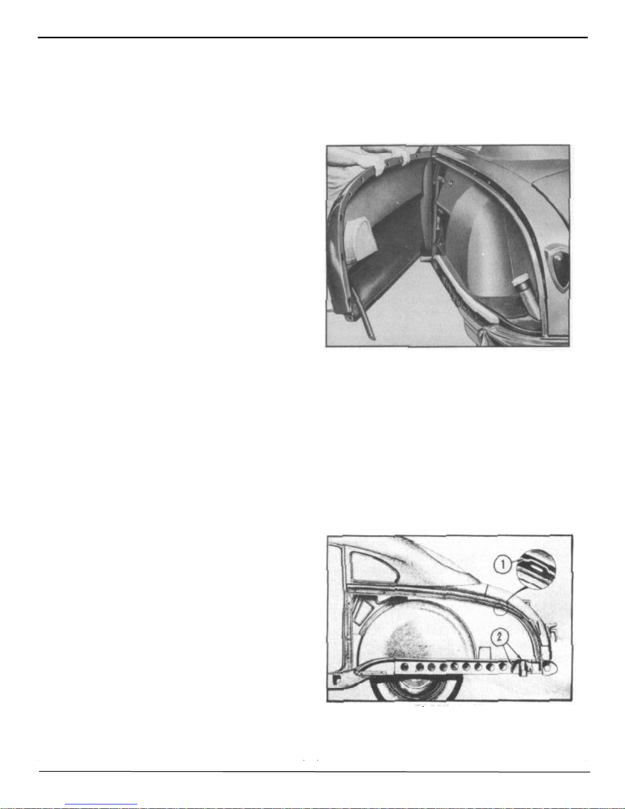
With most damaged bodies, there are parts that
have to be removed to facilitate the repair of the
damaged sections. These parts, whether they are
damaged or not, should be kept in some suitable
container or storage bin to prevent further damage
and eliminate the possibility of parts becoming lost.
Where severe body damage is encountered, it is
best to remove body trim parts, all of which are
easily removed, and store them in a clean, dry
place. By approaching the actual repair job in this
manner, more freedom and better visibility during
the repair operation is possible. Considerable time.
and patience, too, is thus saved in the aligning
operation and in the effective placing of body jacks.
With the body trim parts safely stored out of the
way, the possibility of burning, tearing, or soiling
of upholstered parts is negligible.
8. Remove rear bumper extension at side of fender.
9. Pry off fender panel lower moulding.
10. Remove the two self tapping screws attaching rear
fender panel and moulding retainers to the rocker panel.
11. Remove the 7 bolts and nuts attaching the fender
panel and moulding retainers to the rocker panel.
12. Lift off rear fender. See Figure 14.
REMOVAL & INSTALLATION
PROCEDURES
REAR FENDER
REMOVAL:
1, Remove rear wheel cover and rod assembly.
2. Remove rear seat cushion and remove the end
section of the rear seat back from same side from
whlch fender is to be removed.
3. Remove rear quarter window garnish moulding
and the valance reveal moulding.
4. Remove rear quarter inside trim panel.
5. Remove 3 Phillips head screws and two self
tapping screws at door pillar post.
NOTE: On Broughams and Coupes it is necessary to remove the rear quarter window to
allow removal of the three fender attaching
screws located behind the glass. See "Quarter
Window Glass Removal," Page No. 31.
FIGURE 14
INSTALLATION:
NOTE: Before installing rear fender apply a bead of
Permagum No. 576, Part No. 175356 Sealer, starting
from base of rear door hinge pillar and crossing
quarter panel flange to frame at rear and to area at
2 as shown in Figure 15. Care must be taken to
assure that the bead of sealer is unbroken and does
not cross any fender attaching bolt holes.
6. Remove the spare tire from rear compartment to
permit better accessibility.
7. Remove 7 screws inside rear compartment
which fasten fender to rear quarter panel.
FIGURE 15
1. Align fender at door hinge pillar and install attaching
screws. DO NOT TIGHTEN.
Page 26
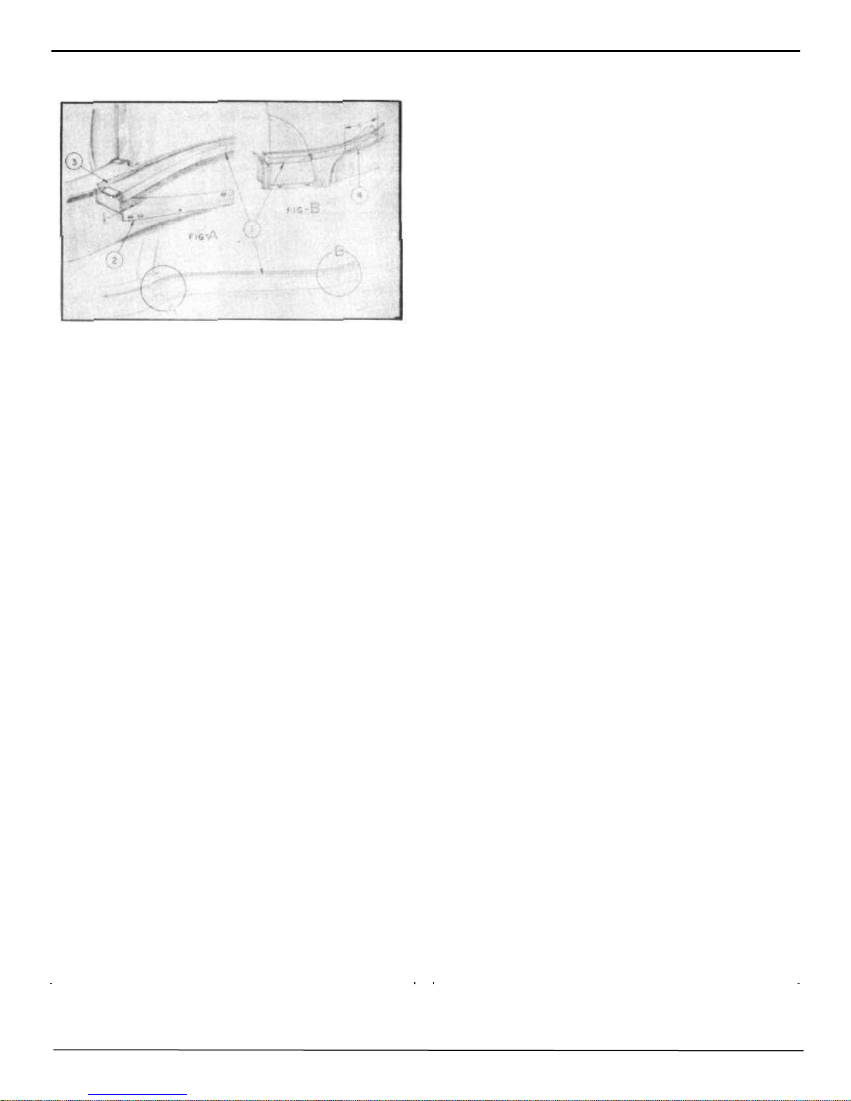
20 BODY MANUAL
2. Attach all upper bolts at quarter panel flange before
attaching fender to rocker panel. DO NOT TIGHTEN.
FIGURE 16
3. Install rear fender seal flush with frame flange,
raising the front end 1/8" to interfere with rocker panel
filler, Figure 16, No. 1 and No. 2. Cement seal tightly
and allow approximately 6" from the end of the seal to
remain loose until the fender is completely installed,
No. 4, Figure 16. Then cement seal securely to frame
flange, No. 3, and fender. TIGHTEN ALL ATTACHING BOLTS AND SCREWS SECURELY.
FRONT FENDER
9. Remove moulding and 4 self-tapping screws
attaching fender and moulding clips to front rocker
panel.
10. Remove kick pad in the front seat compartment
at the dash panel.
11. Remove the screw attaching the door opening
belt weatherstrip to fender and front cowl panel.
12. Remove the 4 bolts from behind the kick pad
which attach the fender to the dash panel and front
hinge pillar.
13. Lift off front fender.
14. Remove all trim and useable parts from damaged
fender and install on new fender.
INSTALLATION :
1. With help of an assistant, align fender at cowl
panel and attach screws at kick panel opening and
front door hinge pillar.
2. Attach fender to radiator baffle side shield, fender
side dust shield, and radiator splash guard.
3. Reverse procedure of removal on balance of installation.
NOTE: Reseal fender at cowl panel and at belt
moulding with dolphinite sealer No. 2465,
REMOVAL:
1. Raise hood and disconnect headlight wires at junction block on radiator support.
2. Remove headlight rim (3 Phillips head screws) and
remove the headlight housing (4 screws).
3. Remove the attaching bolts from the fender and side
dust shield.
4. Remove two bolts attaching fender tie panel and
hood lock lower support to fender.
5. Remove the upper hood prop bolt and allow hood
prop to be removed with fender side dust shield. Support hood during this operation.
6. Raise car and remove front wheel.
7. Remove 3 bolts attaching fender to radiator baffle
side shield.
8. Remove 3 bolts attaching fender to lower radiator
splash guard.
NOTE: Front fender front extension is spot welded
to the fender and will have to be removed with the
fender.
Part No. 175367. If necessary to replace the weatherstrip, proceed as follows:
A. Apply a coating of rubber cement to the surfaces
of the front pillar face and the belt weatherstrip.
B. Press weatherstrip into position then insert and
tighten attaching screws.
FRONT FENDER STONE GUARD
AND PANEL ASSEMBLY
REMOVAL:
1. Remove 4 bolts attaching stone guard and panel
to front quarter dash panel under the fender, 2 bolts
under rubber pad, and one located to the left of hood
hinge.
2. Remove 3 Phillips head screws and speed nuts at
dust shield extension rubber shield.
3. Remove the panel and stone guard.
INSTALLATION:
Reverse procedure of removal.
Page 27
BODY MANUAL 21
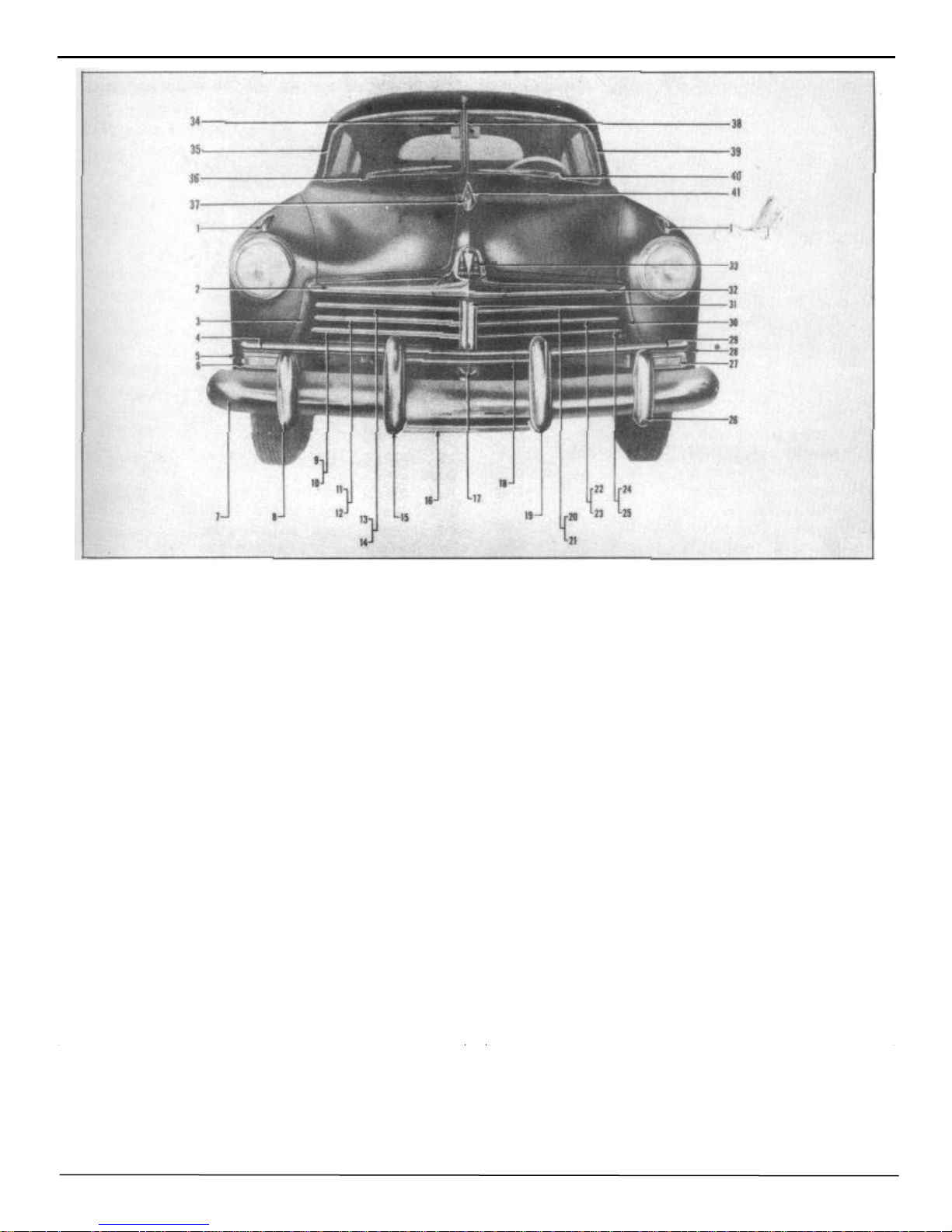
1. Front fender ornament.
2. Hood louver (R.H.)
3. Radiator grille baffle side support (R.H.)
4. Front splash guard moulding
5. Front fender extension assembly (front R.H.)
6. Parking light assembly
7. Front bumper impact bar
8. Front bumper guard (outer R.H.)
9. Radiator grille moulding (lower R.H.)
10. Radiator grille baffle (lower R.H.
11. Radiator grille moulding ( center R. H.)
12. Radiator grille baffle (center R.H. )
13. Radiator grille moulding (upper R.H.)
14. Radiator grille baffle (upper R.H.)
15. Front bumper guard assembly (inner R.H.
16. Front bumper license guard (lower)
17. Radiator grille center bar (lower)
18. Front bumper license guard (upper)
19. Front bumper guard assembly (inner L.H.)
20. Radiator grille moulding (upper L.H.)
21. Radiator grille baffle (upper L.H.)
FIGURE 17
22. Radiator grille moulding (center L.H.)
23. Radiator grille baffle (center L.H.
24. Radiator grille moulding (lower L.H.)
25. Radiator grille baffle (lower L.H.)
26. Front bumper guard (outer L.H.)
27. Parking light assembly
28. Front fender extension assembly (front L.H.)
29. Front splash guard moulding
30. Radiator grille baffle side support (L. H.)
31. Radiator grille center bar
32. Hood louver (L.H.)
33. Hood front ornament assembly
34. Center windshield reveal moulding ( R. H.)
35. Windshield reveal moulding (R.H.)
36. Pulley housing and cable assembly ( R. H.)
37. Hood crest assembly
38. Center windshield reveal moulding
(L. H.)
39. Windshield reveal moulding (L.H.
40. Pulley housing and cable assembly (L.H.)
41. Hood crest ornament.
Page 28

22 BODY MANUAL
RADIATOR
REMOVAL:
1. Drain radiator and disconnect hoses.
2. Remove two sheet metal screws attaching deflector shield
to fender tie panel.
3. Remove headlight wiring from retaining clips at the front
of radiator.
4. Remove 4 hex head bolts attaching radiator to "U" channel
and remove radiator.
INSTALLATION:
Reverse procedure of removal.
RADIATOR "U" CHANNEL WITH
RADIATOR REMOVED
REMOVAL:
1. Remove headlight junction blocks; leave wires attached.
2. Remove two attaching bolts (each side) from radiator
mounting channel to fender.
3. Remove attaching bolts from mounting channel to fender
tie panel.
4. Remove the bolt attaching the bottom of mounting channel
to frame front cross-member. Remove channel from car.
INSTALLATION:
Reverse procedure of removal.
separately.
1. Remove complete front bumper assembly.
2. Remove three bolts at each side attaching splash
guard to radiator grille panel.
3. Remove bolt at grille lower center bar and the bolt
attaching center plate to right and left hand splash guard.
4. Slide splash guard out.
INSTALLATION:
Reverse procedure of removal.
RADIATOR FRONT SPLASH
GUARD AND MOULDING
REMOVAL:
1. Remove front bumper center grille guard.
2. Remove one bolt (each side) attaching front splash
guard (center) to front fender and lower splash guard.
3. Remove two brass nuts and clips (each side) under
fender attaching fender to splash guard moulding.
4. Remove bolt attaching splash guard to grille lower
center bar and remove splash guard.
INSTALLATION:
RADIATOR GRILLE BAFFLE
(UPPER)
(Right or Left)
REMOVAL:
1. Remove center support bar moulding.
2. Remove screw at front and rear of center bar.
3. Remove one screw from under fender and one screw at
grille baffle side supports. Remove baffle from car.
INSTALLATION:
Reverse procedure of removal.
RADIATOR SPLASH GUARD
(Right or Left)
REMOVAL:
NOTE: The splash guard consists of two pieces joined at
center support. Either right or left side may be removed
Reverse procedure of removal.
RADIATOR GRILLE CENTER BAR
(UPPER)
REMOVAL:
1. Remove two screws and remove the center bar
support moulding.
2. Remove bolts attaching grille baffles to center bar.
3. Remove two bolts attaching center bar to fender tie
panel and to front splash guard.
4. Remove center support and splash guard center plate.
Remove bar from car.
INSTALLATION:
Reverse procedure of removal.
Page 29
FENDER AND GRILLE SIDE
SUPPORT
(Right or Left Hand)
REMOVAL:
1. Remove the screws attaching the radiator grille baffles
to side and center support. Remove baffles.
2. Remove five bolts under fender attaching the side
panel to fender.
3. Remove the three bolts, nuts, and shakeproof washers
attaching the side support to the radiator mounting channel.
4. Remove three bolts, nuts, and shake- proof washers
attaching the side support to the lower front splash guard.
5. Remove the front splash guard and moulding and
remove the side support from the car.
BODY MANUAL 23
INSTALLATION:
Reverse procedure of removal.
RADIATOR SPLASH GUARD
REMOVAL:
1. Remove two brass nuts and clips (each side) under
fender attaching moulding to front fender lower extension.
2. Pry off moulding with a screwdriver. Use care if
moulding is to be used again.
INSTALLATION:
Snap moulding into place and attach to fender in reverse
procedure of removal.
ENGINE HOOD
REMOVAL:
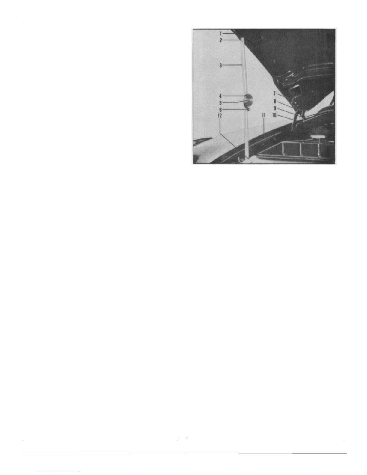
FIGURE 18
HOOD ADJUSTMENT
1. Loosen the two bolts, ( 9 and 10), which attach the hood
hinge to the cowl just enough to allow for backward or
forward movement.
2. Loosen screws (7 and 8) attaching hinge arm to hood,
(each side).
NOTE: Forward and backward adjustments and up
and down adjustments can now be made at the rear of
the hood. Up or down adjustments at the front of the
hood can be made by raising or lowering the three
rubber bumpers mounted on the front fender tie panel
and adjusting the spring retainer bolt mounted on the
hood lock upper support.
3. After all adjustments have been made, tighten all bolts
and lock nuts securely.
HOOD LOCK UPPER SUPPORT
1. Raise and place prop under front of hood (1), Figure
18.
2. Remove two hood prop bolts ( 2), (one on each side).
Hood props ( 3) remain attached to fender side dust
shields ( 11).
3. Remove the two hood hinge bolts, (7 and 8), from each
side at rear of hood.
4. With a helper, remove hood from car.
INSTALLATION:
Reverse procedure of removal and adjust at hood hinge
bolts.
REMOVAL:
1. With a screwdriver remove the spring retainer bolt (2)
from the attaching nut and remove retainer and spring,
Figure 19.
2. Remove the four attaching nuts and washers ( 1) from
lock support plate. 3. Remove the two sheet metal screws
from bracket at rear of assembly and slide assembly to one
side and remove.
INSTALLATION:
Reverse procedure of removal. Adjust locking spring by
turning slotted retainer assembly to left or right.
Page 30
24 BODY MANUAL
FIGURE 19
HOOD LOCK LOWER SUPPORT
FENDER TIE PANEL AND HOOD
LOCK LOWER SUPPORT
REMOVAL:
1. Raise hood and disconnect hood lock control wire.
2. Remove two bolts (each side) attaching fender tie
panel and hood lock support to fender bracket.
3. Remove two bolts attaching the fender tie panel and
hood lock support to radiator mounting channel.
4. Remove two bolts attaching fender tie panel to the
front fender skirt.
5. Removing one bolt attaching hood lock support to
radiator grille center support and remove the support
assembly from the car.
INSTALLATION:
Reverse procedure of removal.
REMOVAL:
1. Disconnect flood lock control wire.
2. Remove 4 bolts attaching hood lock lower support to
fender tie panel and remove lower support from car.
FIGURE 20
INSTALLATION:
Reverse procedure of removal. Lock hood control wire
securely and apply water resistant grease to hood lock
release catch.
HEADLINING
Preparatory to headlining removal, remove the following trim parts:
A Sun visors
B Rear view mirror
C Front dome lamp lens assembly
D Upper and lower windshield garnish moulding
E Windshield inside center trim bar
F Windshield retainers
G Windshield glass
H Rear seat cushion, back rests, and center arm rest
I Rear window
J Rear package shelf
K Rear quarter window garnish mouldings
L Rear dome lamp lens assembly
NOTE: HANDS MUST BE CLEAN AT ALL
TIMES WHEN WORKING ON THE INTERIOR
TRIM OF A BODY.
REMOVAL:
1. Remove upholsterer's tacks from around rear window
opening and rear quarter window openings and the
cardboard tacking strips at the extreme rear edge of the
headlining on the package shelf. Pull headlining loose
from cement.
Page 31

BODY MANUAL 25
2. Remove headlining from glazier's points around upper windshield opening., Use a screwdriver to pry open these glazier's
points to facilitate installation of new headlining.
3. With a sharp knife slit the headlining on both sides, front to
rear, along the side retainers; remove roof bows from rubber
grommets and remove headlining from body.
4. Loosen screws in the headlining slide retainers and remove
scrap material from glazier's points. RETIGHTEN
SCREWS SECURELY.
5. Remove all old cement from around rear window and rear
quarter window openings and windshield opening. Apply new
cement to these areas and allow it to become tacky before
beginning the new installation.
INSTALLATION:
NOTE: BEFORE REMOVING ROOF BOWS FROM
OLD HEADLINING, CONSULT ROOF BOW COLOR
CHART ON PAGE 9 FOR THE CORRECT PLACEMENT OF THE BOWS IN THE NEW HEADLINING.
THE CORRECT PLACEMENT OF THE ROOF BOWS
IN THE HEADLINING IS VERY IMPORTANT.
1. After double checking to make certain that the roof bows
have been installed in their proper sequence in the new headlining, start the installation into the body with the rear bow. (Leave
the first two bows hanging loosely in their grommets. Do not
snap up into the support brackets. This prevents undo stretching
of the material at this point.) Work progressively toward the
front installing each roof bow into its rubber grommet and
support bracket, leaving the front bow hanging loosely in the
rubber grommets.
2. Move to the rear of the body and snap the two rear roof bows
into the support brackets. Press headlining temporarily into the
cement at the top center of the rear window opening. (This
holds the headlining out of the way for installation of the
cardboard tacking strips.) Pull headlining down evenly at cardboard tacking strips on both sides and tack the strips securely at
the rear package shelf.
3. Pull headlining tight and press into cement around rear.
window opening. Snip the material at the corners of the opening to assure a smooth fit and prevent pleats.
Replace upholsterer's tacks in rear window opening.
Trim surplus material from around rear window opening. Cut a separate piece of headlining material approximately 24 inches long and 10 inches wide and install
into cement at bottom edge of rear window opening.
Tuck material under the edges of the headlining and
secure with upholsterer's tacks. (This separate piece of
material covers the panel between the lower edge of the
rear window and the rear package shelf. Material
should be wide enough to extend to the package shelf
and be held in place by the rear package shelf trim
board.)
4. Cut the headlining material at the corners of the rear
quarter windows and press firmly into the cement.
Secure with upholsterer's tacks.
5. Re-install rear package shelf trim board. Cement and
tack into place at the front edge.
6. Now move to the front of the body and snap the front
roof bow into the support brackets. Stretch the headlining forward and, beginning at the center of the windshield opening, attach headlining to glazier's points in
the upper windshield opening. After the headlining is
securely hooked on the glazier's points, hammer the
points flush with the windshield opening. (This assures
perfect fit of windshield sealing strip and prevents leaks
at this point.) Trim away surplus material.
7. Next, using Tool J-2772, carefully tuck the edges of
the headlining up under the side retainers. (Before
starting this operation check to be sure that the side
retainers are fastened securely.) Use the tool carefully
in this operation. Start at the front and work toward the
rear, stretching the headlining as the work progresses.
8. Carefully slit the headlining at the dome lights and
install the dome light lens assemblies. NOTE: Trim
away only enough material at the dome lights to
clear the bulb recess in the lamp base. Headlining is
held in place at this point by the dome lamp lens
assembly; therefore do not trim away more material
than is absolutely necessary.
9. Re-install windows and all trim parts removed prior
to headlining removal operations.
Page 32

26 BODY MANUAL
REPLACING BROKEN
WINDSHIELD
NOTE: On radio equipped cars it is necessary to
remove the radio antenna lead wire assembly prior to
the windshield installation.
4. Using a dull putty knife, Figure 22, pry between the
rubber weatherstrip and the chrome reveal moulding to
loosen and remove the windshield glass and weatherstrip.
NOTE: Glass is removed from the inside.
FIGURE 21
REMOVAL:
1. Remove the rear view mirror (A), Figure 21, and antenna
control knob.
2. Remove antenna lead plug from radio. Loosen lock nut (C)
at joint cover (E), and remove nut under dash attaching lead
rod assembly at moulding joint cover (E). Lower the lead rod
and detach from lead wire on control. Remove windshield
inside center bar.
3. Remove antenna windshield inside center bar (D), moulding joint cover (E), upper and lower windshield garnish
mouldings (H and F), and four steel windshield retainers (G
and H).
FIGURE 22
FIGURE 23
INSTALLATION:
1. Remove all old windshield sealer. With a putty
knife apply enough new sealer around windshield
opening to squeeze out when glass is installed, Figure
23. Mask off the upholstery material around the
windshield opening to prevent soiling during the
installation.
NOTE: Right and left hand rubber seals are used.
When proper seal is on glass, ribbed surface will
be forward and rubbers will fit properly at inner
corners of glass.
2. Place rubber weatherstrip on new glass and place
glass in the windshield opening from the inside of the
car. 3. Maneuver glass into position by carefully
lifting inside lower corner with a tapered wood
wedge. Shim as required along bottom of weatherstrip and glass assembly to bring inner edge parallel
to center bar. Locate shims so that they will not
interfere with installation of windshield retainers (G
and H), Figure 21.
Page 33

BODY MANUAL 27
4. Install one center windshield retainer to secure windshield in proper position.
NOTE: When installing windshield retainers do not install the outside retainer (next to front hinge pillar).
5. Install the remaining retainers and apply soap stick to
the curved portion of the retainer that contacts the windshield rubber weatherstrip. The retainers will then slide
down into position when tightened.
6. Remove masking from upholstery and install all trim
and radio parts removed prior to removing windshield.
7. Carefully remove all excess sealer with Hudson fabric
cleaner.
2. Press the lock retainer back into position by hand as far
as possible; then, using a fiber driving tool and a hammer,
drive the retainer in flush with the edge of the door.
FIGURE 25
DOOR STRIKER PLATE
The door striker plate (3), Figure 25, is mounted on the
body pillar and is attached to a tapping plate on the inside
of the pillar.
FIGURE 24
FRONT DOOR LOCK CYLINDER
REMOVAL:
Insert a screwdriver under the flanged edge of the lock
retainer (B), Figure 24, and pry outward. This will release
the lock assembly for removal from the door. (Leave lock
retainer in the door.) Pull out lock assembly.
INSTALLATION:
1. From the inside of the door, push a stiff wire, or an awl,
thru the hole (C) in the door and lock retainer to the
outside panel. Place recessed end of lock shaft on the
point of the awl and, keeping the two firmly together,
press the lock assembly into the door, using the awl as a
guide.
REMOVAL:
Remove three Phillips head screws (1) from striker plate
and remove plate.
NOTE: With the striker plate removed, to remove
tapping plate (2), loosen trim (4) at pillar and lift plate
out of retainer (5).
ADJUSTMENT:
1. Loosen the three Phillips head screws (1) sufficiently to
allow striker plate to be moved easily with the fingers.
2. Adjust height of striker plate to give correct alignment
with the door latch bar.
3. Adjust inward position of striker plate to hold door
firmly against weatherstrips.
NOTE: When making inward adjustment, be sure that
back of striker plate is parallel to the inside flange of
the body pillar (A).
4. Tighten screws (1) securely.
5. Close door to bring latch bar into safety catch position.
Door should not open when a reasonable pull is exerted.
Page 34

28 BODY MANUAL
6. If door opens easily without pushing the handle button,
loosen screws as in step one and rotate bottom of striker
plate inward. (C). Tighten screws and re-check.
FIGURE 26
DOOR OUTSIDE HANDLE
REMOVAL:
3. Install pocket trimboard.
4. Install valance by inserting lower flange between door
and pocket trimboard; and, with slots in line with trimboard clips, force valance down into position and install
screws.
5. Install arm rest, garnish moulding, lock release knob,
and door handles.
To remove the door outside handle, remove Phillips head
screw (A), Figure 26, from edge of door. Push handle
forward and lift handle out of door.
INSTALLATION:
To install, reverse procedure of removal.
DOOR TRIM PANEL
(Front and Rear)
REMOVAL:
1. Remove inside door handles.
2. Remove lock release knob and garnish moulding.
3. Remove two screws from underside of arm rest and
remove arm rest.
4. Remove valance by extracting exposed screws and
sliding valance up from between door and trim panel.
5. Remove door pocket trim board (clips).
6. Remove door trim panel (clips).
INSTALLATION:
1. Repair any damage to door inside liner with Mystik
tape before replacing trim panel.
2. Install door trim panel by engaging the bottom retainer
and aligning the clips before driving in place.
FIGURE 27
DOOR WINDOW REGULATOR
(Front)
REMOVAL:
1. Remove trim panel. See Page 28.
2. Remove garnish moulding spacer wood block.
3. Cut inner liner as shown in Figure 27 for sedans and
Figure 28 for coupes and broughams.
4. Remove screw (A) from inside upper end of center
glass channel and screws (B) which attach center glass
channel to door inner panel. (Do not remove center glass
channel from door.)
5. Remove screws (C) attaching regulator to door inner
panel.
6. Lower window to bottom of door and release regulator
cross arms from glass channel on sedans. On coupes and
broughams disconnect regulator from cross arm assembly. (A stud on the regulator arm is retained in the cross
arm assembly by a spring clip.)
7. Remove regulator through opening in bottom of door.
Page 35

FIGURE 28
BODY MANUAL 29
4. Remove 4 screws (A) holding regulator to door inner
panel.
5. Lower window to bottom of door and release regulator
from glass channel. 6. Remove regulator through opening
at bottom of door.
INSTALLATION:
Reverse procedure of removal and repair damage to door
inner liner with Mystik tape.
INSTALLATION:
Reverse procedure of removal and repair damage to door
inner liner with Mystik tape.
FIGURE 29
DOOR WINDOW REGULATOR
(Rear)
FIGURE 30
DOOR LOCK
(Front and Rear)
REMOVAL:
1. Remove outside door handle.
2. On front doors, remove door lock cylinder.
3. Remove door trim panel. See page 28.
4. Cut door inner liner at (A), Figure 30, front door; or
Figure 31, rear door, and disconnect remote control arm
from lock at D.
5. Remove window channel from lock side of door.
6. Remove three large Phillips head screws (C) from edge
of door and remove lock assembly down and out through
lower opening in door inner panel.
REMOVAL:
1. Remove trim panel. See page 28.
2. Remove garnish moulding spacer wood block.
3. Cut door inner liner as shown in Figure 29.
INSTALLATION:
Reverse the procedure for removal. Repair any damage to
inner liner with Mystik tape.
Page 36

30 BODY MANUAL
FIGURE 31
DOOR REMOTE CONTROL
(Front and Rear)
in bottom of door inner panel.
INSTALLATION:
Reverse procedure of removal and repair door inner
liner with Mystik tape.
DOOR VENTILATOR WING
(Commodore)
REMOVAL:
1. Remove safety lock knob and garnish moulding.
2. Remove ventilator regulator handle and valance.
3. Remove garnish moulding spacer wood block.
4. Cut hole in door inner liner as shown at B in Figure
30 to expose clevis (G) connecting wing to regulator
and remove screw from clevis.
5. Open ventilator wing and press down on top of
frame to release it from upper pivot and lift out ventilator.
REMOVAL:
1. Remove door trim panel. See page 28.
2. Cut door inner liner as shown at A, Figure 30, for front
door or Figure 31, for rear door.
3. Remove three Phillips head screws (E) from triangular
bracket at handle end of remote control arm.
4. Remove anti-rattle spring and pin
(D) from lock end of remote control and withdraw remote
control toward the hinge side of the door.
INSTALLATION:
Reverse procedure of removal. Repair door inner liner
with Mystik tape.
DOOR VENTILATOR WING
REGULATOR
(Commodore)
REMOVAL:
1. Remove door trim panel. See page 28.
2. Cut door inner liner at B in Figure 30.
3. Remove screw from regulator clevis.
4. Remove two screws (F) attaching regulator to door
inner panel and remove regulator down and out through
opening
INSTALLATION:
Reverse procedure of removal. Make sure ventilator
weatherstrip lip is over garnish moulding. Repair
inner liner.
DOOR VENTILATOR WING
(Super)
REMOVAL:
1. Remove safety lock knob and garnish moulding.
2. Remove wood spacer block.
3. Remove screws (B), Figure 27, attaching wing
frame to inner panel.
4. Remove small Phillips head screw (D), Figure 27,
from top of door.
5. Remove screw (A), Figure 27, from inside upper
end of center glass channel.
6. Tilt ventilator assembly and lift out.
7. Remove nut and spring from friction pivot.
8. Remove screw from top of channel to release wing
from channel.
INSTALLATION:
Reverse procedure of removal. Make sure lip of
weatherstrip is over garnish moulding.
Page 37

BODY MANUAL 31
DOOR GLASS
(Front)
REMOVAL:
1. Remove safety lock knob and garnish moulding.
2. Remove small wood block.
3. Remove pocket trim panel.
4. Cut door inner liner as shown in Figure 28.
5. Remove Phillips head screw (A),
6. Remove two screws (B).
7. Remove center glass channel (D) or lower lt into
the door.
8. Tilt glass inward and raise to upper limit of regulator.
9. Release regulator cross arms from glass channel
and remove glass and glass channel.
INSTALLATION:
Reverse procedure of removal.
DOOR GLASS
(Rear)
REMOVAL:
1. Remove safety lock knob and garnish moulding.
2. Remove small wood block.
3. Run glass to within 2" of the top and pull inward on
top of glass to release glass from glass runs.
4. Tip glass inward and further raise window until
glass channel can be released from regulator.
5. Remove glass and glass channel.
INSTALLATION:
1. Insert channel and glass through opening and engage regulator.
2. Run regulator up and down to force glass into
position.
3. Replace wood block.
4. Replace garnish moulding and safety lock knob.
QUARTER TRIM PANEL
(Broughams and Coupes)
REMOVAL:
3. Remove garnish moulding.
4. On Commodore models remove valance.
5. Remove two screws from under side of arm rest and
remove arm rest.
6. Remove pocket trim panel and lower trim panel, attached by clips to inner panel.
INSTALLATION:
Reverse procedure of removal.
QUARTER WINDOW GLASS
(Broughams and Coupes)
REMOVAL:
1. Remove garnish moulding and small wood block._
2. Lower window and release three clips attaching glass
run channel to top of window opening by pulling in on
channel.
3. Remove glass run channel.
4. Pull in on top of glass and raise glass to limit of regulator.
5. Release regulator from glass channel and remove glass
and channel.
INSTALLATION:
1. Pull in on top of inner panel to enlarge opening between
inner and outer panels.
2. Insert glass and glass channel through • opening and
engage regulator.
3. Lower the window and apply a coating of cement to
window opening to seal glass run channel.
4. Insert glass run channel and engage clips in top of
window opening.
5. Raise window and replace wood block and garnish
moulding.
QUARTER WINDOW GLASS
(Business Coupes)
REMOVAL:
1. Removal garnish moulding.
2. Remove small wood block.
3. Remove two screws holding window support to inner
panel. Hold window in position and remove support.
4. Lower glass to free it from glass run channel and lift
out.
1. Remove rear seat cushion and rear seat back.
2. Remove quarter window regulator handle.
INSTALLATION:
Reverse procedure of removal.
Page 38

32 BODY MANUAL
QUARTER WINDOW GLASS
(Sedans)
REMOVAL:
1. Remove garnish moulding.
2. Remove four sheet metal screws attaching glass frame
to window opening and remove glass and
3. Remove nut And spring from friction pivot.
4. Remove screw from upper pivot and remove window
from frame.
INSTALLATION:
Reverse procedure of removal.
QUARTER WINDOW REGULATOR
(Broughams and Coupes)
REMOVAL:
1. Remove quarter trim panel. See page 31.
2. Remove quarter panel inner liner.
3. Remove quarter window glass.
4. Remove four Phillips head screws attaching regulator
to inner panel and remove regulator through lower opening in inner panel.
INSTALLATION:
Reverse procedure of removal.
REAR WINDOW GLASS
REMOVAL:
Insert a headlining installer tool or a dull putty knife
under the inner lip of the rubber weatherstrip and pry up
and out. At the same time pound outward on the glass
with a rubber hammer.
INSTALLATION:
1. Clean all old cement from around rear window opening.
2. Install new rubber weatherstrip around rear window
glass. (On Commodore models install chrome reveal
moulding on rubber weatherstrip and clip in position). 3.
Tie a stout cord around the center recess in the rubber
channel. Tie tightly enough to draw the inner edges of the
rubber channel within the limits of the rear window opening.
4. Apply a ribbon of sealer to the rubber channel and
insert the window from the outside. Tap the window
sharply around the outside edge to seat firmly into window opening.
5. From the inside of the car, remove the cord holding the
rubber channel and let the channel inside lip settle into
position around the inside window opening. Clean off all
excess sealer carefully with Hudson fabric cleaner.
INSTRUMENTS AND
INSTRUMENT PANEL
STARTER SWITCH
REMOVAL:
1. Turn ignition switch (27), Figure 32, to "off" position.
2. Remove Phillips head screw from the under side of
instrument panel and remove switch (3).
INSTALLATION:
Reverse procedure of removal.
LIGHT SWITCH AND CIRCUIT
BREAKER ASSEMBLY
REMOVAL:
1. Disconnect negative battery cable at battery.
2. Loosen Allen set screw in control knob (32) and remove knob.
3. Using a suitable spanner, remove escutcheon nut and
escutcheon.
4. Remove switch and remove wires from switch.
INSTALLATION:
Reverse procedure of removal. Keep battery disconnected
until operation is completed.
IGNITION SWITCH
REMOVAL:
1. Disconnect negative battery cable at the battery to
prevent accidental short circuits.
2. Remove Phillips head screw from underside of instrument panel, and remove switch (27).
3. Remove wires from switch terminals.
Page 39

BODY MANUAL 33
FIGURE 32
INSTALLATION:
Reverse procedure of removal. Keep battery disconnected
until operation is completed.
INSTRUMENT PANEL LAMP
RHEOSTAT
REMOVAL:
1. Turn light switch to "off" position.
2. Remove two screws from under side of instrument
panel and remove rheostat (29).
3. Remove wires from rheostat.
INSTALLATION:
Reverse procedure of removal.
WINDSHIELD WIPER CONTROL
REMOVAL:
1. Loosen screw attaching control wire to wiper motor
and remove wire from motor.
2. Loosen Allen set screw in control knob and remove
knob (36).
3. Using a suitable spanner, remove escutcheon nut and
escutcheon.
4. Remove wiper control from panel and pull control wire
through dash.
INSTALLATION:
Reverse procedure of removal.
CIGAR LIGHTER
REMOVAL:
1. Disconnect lighter wire from light switch.
2. Depress springs on lighter cylinder at rear of instrument
panel and push out of instrument panel.
NOTE: Cigar lighter knob may be unscrewed from
lighter.
INSTALLATION:
Reverse procedure of removal.
Page 40

34 BODY MANUAL
INSTRUMENT SWITCH PANEL
(Left)
REMOVAL:
1. Remove starter switch (3), Figure 32.
2. Remove left half of chrome finish strip at steering
column.
3. Remove Phillips head screw from
left end el and one from the underside at right end.
4. Remove one 3/8 nut from bolt in top of panel. Bolt
extends under locker box. 5. Remove panel and ornament (D).
INSTALLATION:
Reverse procedure of removal.
INSTRUMENT SWITCH PANEL
(Right)
NOTE: Disconnect negative battery cable at battery before removing switches.
REMOVAL:
1. Remove ignition switch (27), Figure 32.
2. Remove instrument lamp rheostat (29).
3. If car is equipped with Drive-master, remove
Drivemaster control switch (30).
4. Remove light switch (32).
5. Remove cigar lighter (33).
6. Remove windshield wiper control (36).
7. Remove three screws from the underside of switch
panel and one from the right end of the panel.
8. Upper edge of panel is attached to instrument panel
by three bolts; one is located under the locker box,
one under the radio, and one under the inner corner of
the glove compartment. Remove the nuts from these
bolts using a 3/8" socket and extension.
9. Remove right hand half of chrome finish strip (G)
at steering column.
10. Remove switch panel (E) and panel ornament (F).
INSTRUMENT FINISH PANEL
REMOVAL:
1. Remove ornamental trim.
2. Remove locker box and glove compartment door bumpers.
3. Remove two screws from each end of finish panel.
Screws are exposed when glove-compartment and locker
box doors are open. On models not equipped with locker
box, remove screw from inside upper edge of left section
of finish panel to release hinged panel and expose_
screws. On earlier models three screws hold this section
of the panel in place.
NOTE: On radio equipped cars it is necessary to remove control knobs and escutcheon nuts.
INSTALLATION:
Reverse procedure of removal.
SPEEDOMETER
REMOVAL:
1. Remove instrument finish panel (A). Figure 32.
2. Remove four screws attaching speedometer to instrument panel and remove speedometer from panel.
3. Pull the beam indicator and instrument lamps and
sockets from the speedometer and unscrew the cable.
INSTALLATION:
Reverse procedure of removal.
CLOCK
REMOVAL:
1. Remove instrument finish panel (A), Figure 32.
2. Remove four screws attaching clock to instrument
panel and remove clock (39) from panel.
3. Pull the instrument lamp and socket from the clock.
4. On electric clocks, disconnect feed wire at fuse connector.
INSTALLATION:
Reverse procedure of removal.
INSTALLATION:
Reverse procedure of removal.
Page 41

BODY MANUAL 35
FUEL GAUGE
REMOVAL:
1. Remove instrument finish panel (A), Figure 32.
2. Remove four screws attaching instrument cluster to
instrument panel and pull out cluster.
3. Remove two mounting screws from base of gauge and
disconnect wires.
4. Remove gauge (10) from back of cluster.
INSTALLATION:
Reverse procedure of removal.
TEMPERATURE GAUGE
Remove and install same as fuel gauge.
FIGURE 33
WINDSHIELD WIPER
The windshield wiper mechanism consists of a vacuum
operated motor assembly, two spring loaded cable tension assemblies, two pulley housing and cable assemblies, wiper arms, blades, and cables.
WINDSHIELD WIPER MOTOR
ASSEMBLY
The windshield wiper motor assembly is mounted in the
center of the dash under the hood. The motor is connected
by cables to the wiper arms. A vacuum hose connects the
wiper motor directly to the intake manifold or to a vacuum booster pump. The motor is controlled by a slide
valve operated by a wire connected to the dash control.
REMOVAL:
1, Disconnect pulley cables from the wiper motor at (B),
Figure 33.
2. Loosen retaining screw and remove control wire from
slide.
3. Disconnect vacuum hose from motor at C.
4. Remove two bolts (D) attaching wiper motor to mounting bracket and remove motor.
INSTALLATION:
Reverse procedure of removal. Adjust cable tension and
wiper arm travel.
PULLEY HOUSING AND CABLE
ASSEMBLY
The windshield wiper pulley housing and cable assemblies, right and left, are inserted in the openings in the
front cowl panel at the base of the windshield and are
retained on the inside by a bolt and clamp. A burred
bushing is provided for attachment and adjustment of the
wiper arm. The small brass tube in each housing is for use
Page 42

36 BODY MANUAL
with a windshield washer attachment.
REMOVAL:
1. Disconnect cables at the wiper motor and lift free of the
tension assemblies.
2. Remove wiper arms and blades. The wiper arms are
retained on the burred bushings by a spring clip which is
released by pulling the arm up and away from the windshield.
3. Remove the bolt and clamp from the underside of the
cowl panel.
NOTE: To remove right hand assembly, glove compartment must be removed to gain access to this bolt
and clamp.
4. Draw cables through dash to the inside of car.
5. From the outside, lift out pulley housing and cables.
6. Remove gasket.
INSTALLATION:
Reverse procedure of removal. Adjust tension and wiper
arm travel.
NOTE: Right and left pulley housing and cable assemblies differ slightly. See that small brass tube is on the
inside of the assembly toward the center of the car.
ADJUSTMENT:
Windshield wiper cable tension is set at the factory but
requires adjustment whenever an over-travel of the
blade occurs at high speed or a reduction of travel
occurs on dry or snow packed glass.
To adjust the tension, insert a 1/2" socket through the
hole provided in the bracket support and loosen the nut
at the bottom of the spring shaft sufficiently to free the
lockwasher between the pulley base and the mounting
bracket. The spring (G) will automatically move the
pulleys (H) and take up any slack in the cables. Hold
the pulleys in the new position and retighten the nut.
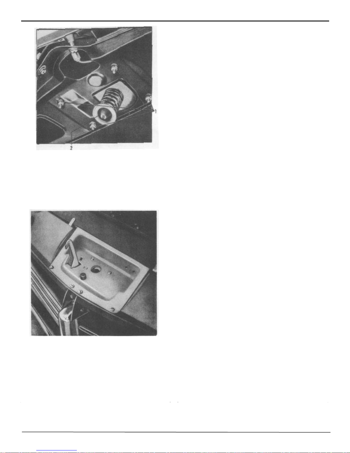
If necessary after adjustment of cable tension, relocate
the wiper arms on the burred bushings so that the
wiper blades rest against the windshield moulding
with wiper in "off" position.
RADIO
INSTALLATION INSTRUCTIONS
CABLE TENSION PULLEY
ASSEMBLY
Cable tension pulley assemblies (E), Figure 33, are
mounted under the hood on the right and left side of the
dash panel. These cable tension pulley assemblies are
spring loaded to maintain approximately 14 pounds tension in the cables.
REMOVAL:
1. Disconnect cables from wiper motor at B, Figure 33,
and lift cables free from pulleys.
2. Remove two screws (F) attaching assembly to support
bracket and remove assembly.
INSTALLATION:
Reverse procedure of removal and adjust cable tension.
NOTE: Right and left cable tension pulley assemblies are
different. An identification mark is stamped on the top of
the plate on which the pulleys are mounted.
1. Install the antenna. (Complete instructions are
furnished with each kit.) Remove door on left hand
side of instrument panel by removing the three screws
from the back.
3. Remove ornament from center of trim panel (above
radio opening) by removing the two face screws.
4. Remove the instrument finish panel and remove the
escutcheon plug from the panel. (See Page 34.)
5. Remove the two bolts from the fire wall and install
the rear mounting bracket. Do not tighten the bracket
at this time.
6. With the dial end of the receiver up, push the
receiver up between the instrument panel and the air
duct. Turn the radio until the knob shafts slide through
the openings in the instrument panel and the tapped
spacers provided on the front plate of the set line up
with the two corresponding holes in the instrument
panel. Bring the receiver forward as far as it will go.
7. With the receiver held in this position, start the two
1/4 x 20 hex head bolts with lockwashers into the holes.
8. Slip the elongated hole in mounting bracket over the
stud on the set and install lockwasher and nut.
Page 43

BODY MANUAL 37
FIGURE 34
9. Before locking the receiver securely in position, place
the instrument finish panel into position over the clock
and note whether or not the radio and trim panel are
centered correctly. If not, move the radio until the dash
trim panel and radio dial escutcheon assembly are in
alignment. Then permanently fasten set in position by
tightening the two front screws and the nut and bolts on
FIGURE 35
the rear mounting bracket. Replace instrument finish
panel and fasten securely.
10. Connect the "A" lead of the set to the battery terminal
of the circuit breaker, Figure 34, mounted on the instrument panel brace over the steering column (Figure 35).
11. Plug in antenna cable (Figure 36).
12. Remove speaker cover plate, and pull speaker leads
through opening in dash.
13. Plug speaker leads into pin socket mounted on speaker. Make sure green wire plugs into green spotted pin
socket.
14. Lower speaker into position, and line up with holes in
the instrument panel. Place speaker grille, included in
radio package:, over speaker, making sure the mounting
holes line up; then fasten securely with the four chrome
plated screws provided in kit.
15. Place tone control knob onto shaft; put on volume
control knob, and tighten set screw (Figure 34). Be sure
there is no binding.
16. Place knob tension spring over the tuning shaft. Put on
trim ring and press on tuning control knob as far as it will
go. Tighten set screw (Figure 34).
17. Replace ornament and door.
Page 44

38 BODY MANUAL
FIGURE 36
18. IMPORTANT: Turn the receiver on and allow it to
operate for approximately fifteen minutes in order for
it to reach normal operating temperature. Tune in a
weak station near 1200 KC. With a small screwdriver
adjust the antenna trimmer, located on the right side of
the receiver, for maximum volume (Figure 36).
AUTOMATIC TUNING
There are six automatic tuning positions, each of which
may be adjusted to any desired station. In order to
simplify the identification of the stations, it is advisable to set the automatic tuning mechanism in sequence
according to frequencies of the stations, beginning with
the station broadcasting on the lowest frequency and
progressing to the station broadcasting on the highest
frequency.
If the positions have not been previously adjusted, proceed as follows:
1. Loosen the first push button by turning it counter
clockwise with your fingers.
2. Turn the manual tuning control knob (Figure 34) to tune
in the desired station. Carefully tune to the middle of the
signal for clearest reception.
3. Push the first push button in as far as it will go. Release
the button, and tighten securely by turning it clockwise
with the fingers.
4. Repeat the above procedure for the remaining five push
buttons.
NOTE: See next page for instructions on radio
interference elimination.
Page 45

INTERFERENCE
ELIMINATION
IMPORTANT: Use the utmost care in the following
operations to insure freedom from motor noise. Be sure
that good ground contacts are made between the interference condensers and the car body. If necessary, clean
away paint or dirt with emery paper. Tighten all nuts and
bolts securely.
BODY MANUAL 39
FIGURE 39
3. Remove bolt on the right side of the ignition coil.
Mount a condenser under this holt. Connect lead to coil
terminal marked (— ). (Figure 39).
FIGURE 37
1. Remove the mounting screw of the voltage regulator
and under this screw mount a condenser. Connect the lead
to the voltage regulator "A" terminal. (Figure 37).
FIGURE 38
2. Install suppressor in center of hole of distributor cap.
Place high tension
lead in top of suppressor. Be sure the suppressor and the
lead are fastened securely. (Figure 38).
HUDSON WEATHER
CONTROL
The Hudson "Weather Control" system is partially built
into every Monobilt body. With the addition of the accessory subunit, a new kind of living comfort is experienced
within the automobile. Fresh, clean, cool air is available
on the hottest or rainiest days, as is comforting warmth
available on the coldest days.
Body Built -In Features:
Adjustable cowl ventilator, no need for a ventilator cover.
Air duct under the cowl for connection of the accessory
unit.
Rain water drain, located in air duct.
Accessory Unit Consists of:
Assembled core shroud and fans with mounting parts.
Air filter for cowl inlet.
Water control valve and thermostat unit.
Control shaft.
Defroster nozzles, R.H. and L.H.
Defroster tubes.
Defroster fan operating switch.
Water hoses and nipples with attaching parts.
Page 46

40 BODY MANUAL
FIGURE 40
USING THE HUDSON
WEATHER CONTROL
The proper use of the Hudson Weather Control is something that everyone who works on Hudson automobiles
should know. The following are instructions for its
While driving the car with the cowl ventilator open and
all windows closed, set the regulator lever (No. 2), Figure
40, at the bottom of the heater in about mid-position. If
this produces too much heat to meet individual requirements, move the lever to the left gradually until the
desired amount of heat is attained. Likewise, if more heat
is desired, move the lever to the right. After this setting is
made, there will be little need for readjustment as the heat
is thermostatically controlled.
If cold air is delivered by the heater while the engine is
warming up, close the cowl ventilator until the engine
heat indicator begins to show that the engine is warming
up; then open the cowl ventilator.
Do not adjust the heat control during the engine warm-up
period in an attempt to get quicker heat. The thermostatic
control valve remains wide open until the temperature
rises to the regulated setting; therefore, moving* the control lever will not increase the delivery of heat.
When the regulator lever is moved to the extreme right,
the thermostatic valve is locked open, and maximum heat
output is attained regardless of car temperature. When the
regulator lever is moved to the extreme left, the valve is
locked closed, and no water flows thru the heater. This
position is used for summer driving and permits the opening of the cowl ventilator in hot or rainy weather. The
cowl duct is fitted with a trap to prevent water entering the
car thru the open cowl ventilator.
When starting out in a cold car with a full passenger load,
some window fogging may occur.
This may be reduced by turning on the defroster fan, which
Page 47

BODY MANUAL 41
is controlled by the switch knob (No.3), Figure 40, on the
front of the heater. The fan should then be turned off after
the windows are clear.
The defroster fan should be also turned on while standing
or while driving at low speeds (either summer or winter
driving) when the forward movement of the car is not
sufficient to supply the required air flow thru the cowl
ventilator. The cowl ventilator must be open when the
defroster fan is being used.
Excessive air flow encountered at high speeds may be
reduced by partially closing the cowl ventilator. This in
turn increases the temperature of the air delivered by the
heater.
A vertical sliding knob (No.1), Figure 40, located on the
left side of the heater case, controls the amount of air
directed on the driver's feet.
CAUTION: When installing the front floor mat, be
sure that enough clearance is allowed so that this
secondary drain hose is not pinched together.
ELECTRICAL SYSTEM
SAFETY FEATURES
Fuses Capacity Where Located
Heater 10 amp. Heater Lead Wire
Radio 10 amp. Radio Lead Wire
Cigar Lighter 14 amp. Lead Wire
Elec. Clock 3 amp. Lead Wire
Direction Ind. 14 amp. Fuse block - Left side,
rear compartment.
CIRCUIT BREAKERS
Headlights 30 amp. On lighting switch
Auxiliary
Lights 30 amp. Forward of
steering
Top Power Unit 30 amp. column
FIGURE 41
Maximum heat is obtained with this knob in the "up"
position.
NOTE: In addition to the rain water drain which is in
the cowl duct, there is a secondary drain at the extreme bottom of the Weather Control unit. This secondary drain takes care of any rain water or snow that
may be blown in, in the event the car is left standing
with the cowl vent open.
FRONT WHEEL ALIGNMENT
There are five general factors to front wheel alignment:
Pivot Pin Inclination
Caster
Camber
Toe-in
Toe -out
All of these factors are very closely related, and each has
a very definite purpose. They control the front wheels and
steering under varying conditions of weight and speed.
When the angle of adjustment of any one of these factors
is changed due to wear or accident, the relationship between them is destroyed. Each angle depends upon the
proper setting of the other four to make the front wheels
lead properly.
In making corrections to front wheel alignment, or when
installing new front wheel suspension parts, all five angles
in both front wheels should be checked in the following
order.
Page 48

42 BODY MANUAL
FIGURE 42
PIVOT PIN INCLINATION:
Pivot Pin Inclination is the inward tilt of the steering
spindle pivot pin at the top. The correct degree of
pivot pin inclination is 3°36' . If the pivot pin inclination and the camber are incorrect, it is likely due
to worn pivot pin bushings. If the camber is incorrect
and the pivot pin inclination is correct, the spindle is
bent. Camber should not be more than specified
1-1/2°; however,a decrease in camber if pivot pins
are not loose in the bushings, is not detrimental to
steering unless an actual reverse camber exists.
CASTER:
Caster is the backward tilt of the steering spindle
pivot pin. Positive caster is obtained by tilting the
top of the pivot pin toward the rear of the car.
Negative or reverse caster is the tilting of the top of
the pivot pin toward the front of the car.
Positive caster imparts a trailing action. The correct
amount of caster helps to keep the front wheels in the
straight ahead position. When turning the wheels
away from the straight ahead position, caster and
pivot pin inclination act as a lever in returning the
front wheels to the straight ahead position. No caster
correction should be made until after the camber
angle and pivot pin inclination angle have been
checked.
WHEN CHECKING THE CASTER THE WHEELS
SHOULD BE TURNED ON THEIR BEARINGS TO
BRING THE HIGH SPOT, OR THAT PORTION OF
THE TIRE WITH THE GREATEST RUNOUT, TOWARD EITHER THE FRONT OR THE REAR OF
THE CAR.
The amount of caster the front wheels require depends on
the friction in the pivot pins, tie rod ends and the steering
linkage. A well lubricated car requires less caster than
does one that is frequently lubricated.
One complete turn of the eccentric bushing changes caster
1/2°. Set caster to 1° preferred, plus or minus 1/2°. Setting
must be equal on both front wheels if possible, but never
allow over 1/2° variation between right and left wheels.
CAMBER:
Camber is the outward tilt of the front wheels at the top
and is generally measured in inches or degrees. It is
seldom necessary to turn the eccentric bushing more than
one half turn to obtain 1/2° camber adjustment. This half
turn should be all that is ever necessary for camber adjustment and will also cause a minimum of caster change.
WHENEVER THE ECCENTRIC BUSHING IS
TURNED, THE CASTER, CAMBER, AND PIVOT
PIN INCLINATION MUST BE CHECKED, AS ALL
THREE ARE AFFECTED.
Page 49

BODY MANUAL 43
When camber is increased, pivot pin inclination is decreased. Decreasing camber increases pivot pin inclination.
TOE -IN:
Toe-in is the drawing together of the front wheels at the
front. This is accomplished by making adjustments at the
tie rod ends which establish a shorter distance between
the wheels at the front than at the rear. Camber tends to
cause the wheels to separate or spread at the front, and
sufficient toe-in is necessary to compensate for this tendency and make the wheels run straight. Accurate toe-in
is of great importance in obtaining maximum tire life.
Toe-in must be within the definite limits of 0" to 1/16"
MEASURED AT THE WHEEL RIM.
TOE -OUT:
Toe-out on turns is controlled by the movement and
angularity of the steering arms. Toe-out is checked by
turning the wheels to the right or left as far as possible.
When the front wheels are turned to the right or left, they
separate slightly at the front. This separation increases as
the turn is increased from the straight ahead position. The
wheel making the inside turn turns at a greater angle than
does the outside wheel; thus toe-out is very necessary to
keep the two front wheels turning together properly
around curves and corners. The amount of toe-out increases due to the change in angle between the tie rods
and steering arms.
RIDING HEIGHT AND COIL
SPRING SAG
When the car does not seem to be level, and a check of the
coil spring height is desired, place the car so that the front
end is level crosswise and then rock the car sidewise
several times and allow the car to settle. This will remove
any binding that might cause a dimensional difference.
TOE-OUT MUST ALWAYS BE CHECKED WITH
THE WEIGHT OF THE CAR ON THE WHEELS.
Front wheels must rest on full floating turntables, and the
turning angles should read as follows:
Left Turn
Left Wheel 30° Right Wheel 25°
Right Turn
Right Wheel 30° Left Wheel 25°
The difference between the left and right wheel angle
must not vary more than 30° minutes, plus, or minus,
from specifications.
FIGURE 43
Measure the distance from the top of the lower arm rubber
bomber seat to the bottom of the upper rebound bracket,
which should be 4-1/4" on each side, Figure 43.
If the two measurements vary more than 1/2" between
sides, it is advisable to replace one or both coil springs.
The light and heavy coil springs may be identified by the
part number stamped on the top coil of spring.
Page 50

44 BODY MANUAL
GENERAL INFORMATION
ON APPEARANCE
CLEANING UPHOLSTERY:
There area few items of a general nature to keep in mind
when cleaning upholstery fabrics.
When reference is made to cleaning fluids, use a good
non-inflammable fluid in which carbon tetrachloride is
the principal ingredient.
When cleaning seat cushions and seat backs use a clean
cloth dampened only slightly. Do not saturate to the
extent of soaking the seat pads.
In cleaning soiled areas of the headlining, do not clean
against the nap, If this does happen, smooth the material
while damp by rubbing with the nap with a damp cloth.
Do not push against the headlining while cleaning to the
extent of bringing the material in contact with the roof
silencer panels. The damp material may take further stain
from the silencer panels.
GREASE AND OIL STAINS:
Use reliable cleaning fluid. If the fabric is saturated with
oil, pour the fluid directly on the spot and soak it up by
pressing a white blotter against the spot before cleaning
with a cloth dampened with the fluid.
BLOOD STAINS:
Use cold water. If this does not entirely remove the stain,
pour ammonia on the spot and rub with a clean cloth.
NOTE: DO NOT USE HOT WATER ON BLOOD
STAINS AS IT WILL SET THE STAIN.
CANDY STAINS:
Use hot water on all candy stains that do not contain
chocolate. With chocolate stains, first rub the stain with a
clean cloth dampened with cleaning fluid. Then scrape
with a dull knife and rinse with cold water. In both cases,
after the spot has dried, it it advisable to finish the job by
using cleaning fluid.
CAUTION: AVOID THE USE OF HOT WATER
EXCEPT WHERE SPECIFICALLY RECOMMENDED.
FRUIT STAINS:
REMOVING STAINS:
The following suggestions will prove helpful in removing
various stains to which automobile upholstery is frequently subjected. In using cleaning fluids, always follow
the procedure that is commonly used in removing spots
from clothing; that is, dampen a clean cloth with the fluid
and start cleaning lightly around the OUTSIDE of the
spot, gradually working towards the CENTER. This
method keeps the spot from spreading and is less likely to
leave a ring.
BATTERY ACID:
Pour household ammonia or a solution of baking soda
directly on the spot and allow it to remain for one minute.
Rinse with cold water. It is very important that this
treatment be applied at once as the acid will eat thru the
material within a very short time.
Rub vigorously with a cloth dampened in hot water. When
dry, finish with cleaning fluid.
ICE CREAM:
Follow the same procedure as for fruit stains.
LIPSTICK:
Pour a small quantity of cleaning fluid directly on the
spot. Press. a clean white blotter over the stain. Repeat this
process, using a clean blotter each time, until the stain
disappears.
NAUSEA STAINS:
Use warm soap suds. Sponge the stained area until the
stain is removed. Brush with a whisk broom. Brush with
the fabric pile when wet and against the pile when dry.
Page 51

BODY MANUAL 45
MILK STAINS:
Follow the same procedure as for nausea stains.
WATER SPOTS:
Sponge the entire panel with a cloth dampened with cold
water. Then sponge with cleaning fluid.
CHEWING GUM:
Moisten the gum with cleaning fluid. Remove with a dull
knife and then finish with a cloth dampened with cleaning
fluid.
CLEANING LEATHER:
Stickiness and loss of luster on leather upholstery is due
largely to the use of polishes or preparations which injure
the surface finish. To maintain a bright and clean finish
on leather upholstery is comparatively simple when correctly handled. We suggest the following:
Apply a damp (not wet) cloth with castile soap or a good
grade of saddle soap and rub briskly. Next apply a moist
cloth without soap and go over surface thoroughly. Finish
by rubbing dry with a clean cloth. The gloss finish of the
leather may disappear during the first application. However, it will be restored by the friction produced in polishing with the dry cloth.
Under no circumstances use furniture polishes, oils, or
varnishes on leather upholstery.
Do not use water excessively. When dry, brush with a
whisk broom.
NOTE: RUG MATERIAL IS SET INTO A RUBBER
BASE, AND THE USE OF ANY FABRIC CLEANER
OR GASOLINE SERVES AS A SOLVENT WHICH
WILL CAUSE THE NAP TO BE LOOSENED AND
COME OUT.
PAINT - CARE OF FINISH
POLISHING:
While this type of finish will retain a high gloss for a long
period, it will be necessary at definite intervals, depending
entirely on climate conditions, to give the finish a more
thorough cleaning than is obtained by merely washing.
When the surface film, which will naturally accumulate,
cannot be removed by washing, clean the surface thoroughly with Hudson Liquid Glaze Cleaner, rubbing sufficiently to clean the surface thoroughly. Follow with a
brisk back and forth rubbing with a soft cloth. Follow the
cleaning operation with a protective coat of Hudson Liquid
Glaze Sealer.
RUST:
For the removal of rust, when it occurs, use Hudson Rust
remover, following closely the directions on the container. After rust has been removed from painted surfaces,
refinish according to standard practice. Consult a Hudson
dealer when paint is needed.
ROAD TAR OR OIL:
CLEANING RUG MATERIALS:
For general cleaning, use a whisk broom or vacuum
cleaner. When the rug is new, it will be noted that a small
quantity of the nap is loose and comes out. This is not a
fault in the rug but is merely the loose clippings left in the
pile during the manufacture. Usually after the first cleanings this condition disappears.
REMOVING SPOTS FROM RUG:
Use Ivory soap suds with a sponge, wiping off the suds with
a second dampened sponge as the cleaning progresses.
A good standard brand of tar remover can safely be used
to remove tar and oil without injury to the finish. However, if tar has hardened, it should be softened first with light
grease or gasoline. If gasoline is used, be sure it does not
contain coloring matter or Ethyl fluid. After removing the
tar, it is advisable to polish the surface immediately.
SALT AIR:
Cars that are operated near the seashore should have extra attention to the painted and chromium parts. Weekly washing is
strongly recommended and a thorough cleaning and waxing at
three month intervals will greatly assist in preserving the finish.
Page 52

46 BODY MANUAL
REFERENCE
Source of
Information
Date Subject
Page 53

BODY REPAIR AND METAL
FINISHING
One characteristic of sheet metal is its elasticity; that
is, the ability of the metal to spring back to its
original shape after having been bent. Each type of
sheet metal has a definite "limit of elasticity" depending upon its chemical composition, method of
manufacture, and heat treatment. Metal bent or
formed beyond this limit of elasticity assumes a new
permanent shape and loses most of its elasticity. It
becomes non-elastic. To restore such metal to its
original shape, it is necessary to re-work it by bumping or otherwise. Similarly, if it is desired that sheet
metal retain a bend or curve within its limit of
elasticity, it is necessary to reduce the elasticity and
work the curve into the metal by hammering or
heating, or both.
The ability of sheet metal to resist bending depends
to a certain extent on its physical shape. Metal
shaped into sharp V's or ridges is more difficult to
re-work than is metal shaped in curves or U's. Such
sharp V's or ridges are said to be "locked" into the
metal. In manufacturing the elastic, flat steel sheets
into body panels, the forming dies draw and bend the
steel at strategic points to stiffen the flat steel sheet
and give it rigidity.
BODY MANUAL 47
FIGURE 45
In the above Figure Number 45, the elastic metal in the large
panels is held in position by stiff metal flanges, off-set bends,
mouldings, and short curves.
FIGURE 46
Accidents often create buckles like those shown in Figure 46.
The metal is stiffened in the short bends at the valley and the
surrounding ridges. the metal in the slopes still has most of the
elasticity that it had before the accident.
FIGURE 44
In Figure 44, shown above, a flat sheet is bent in a
short arc beyond the normal elastic limits of the
metal. The metal at the bend becomes stiff and holds
its new position, while the metal on either side of the
bend remains elastic.
FIGURE 47
Metal made stiff and non-elastic by severe impact, Figure 47,
must be reshaped over a dolly block; and, therefore, bumping and
metal finishing is going to require more time and skill than does
the reshaping of elastic metal.
Elastic metal will nearly reshape itself once the stiff areas of the
damage are forced into their original position by the
Page 54

48 BODY MANUAL
forced into their original position by the aligning and
roughing operation.
FIGURE 48
A true "oil can" dent can only occur in a low crowned
panel having elastic metal. The metal has been forced
inward (concave) to no greater extent than the metal
was curved outward (convex) in its original shape.
See Figure 48. No buckle is formed, and such a true
"oil can" dent is reshaped by the internal strains that
are in the metal just as soon as the pressure of the
blow or impact is released. The most to be expected
from an "oil can" dent is minor surface scratches.
There can be no buckles as the metal hasn't been
reformed.
FIGURE 50
The standard practice in beginning to reshape a damaged body
is to remove the dents and buckles in a reverse sequence to
which they occurred -- remove the last dent or buckle first,
Figure 51.
ALIGNING AND ROUGHING
Aligning consists of reshaping a distorted body so that
it is "square" when checked from front to rear, horizontally and vertically.
Roughing consists of reshaping damaged panels to
their approximate original contour as is shown in the
following two illustrations. Roughing operations are
frequently necessary where excess body damage prevents proper body alignment.
FIGURE 49
A roughing operation on an "open" panel that does not
contain reinforced sections is illustrated in Figure 49.
A roughing operation to a damaged body panel that is
a combination of open panel and reinforced construction is shown in Figure 50.
FIGURE 51
The last buckle to form will, when removed, relieve any strains
extending through buckles that were previously formed. One
combined aligning and roughing operation will correct each
buckle, and the manner in which the operation is performed will
vary according to the elasticity of the damaged metal.
FIGURE 52
Figure 52 shows a case where the metal was made non-elastic
in manufacture, and pressure at valley (A) must be constantly
maintained with a body jack while simultaneous pressure is
applied against both ridges and slopes of the buckle.
Page 55

The stiff slopes are corrected at the same time with the valleys
and ridges. The dent is in stages A to B to C to D.
TOOL EQUIPMENT
The proper alignment and repair of doors, cowls, tops,
luggage compartments, and inner body construction cannot be accomplished without a complete, modern set of
the proper body repair tools for reaching all of the open
and closed areas in the modern automobile body.
Body jacks, which are the backbone of all heavy body
repair, are available in a variety of styles and sizes.
BODY MANUAL 49
FIGURE 54
A power body jack must be adaptable for reaching all areas in the
body -- behind inner reinforcements, crowned panels, door headers, and body pillars. It must be constructed to offer easy, simple
operation by one man in any position in the body.
FIGURE 53
Past experience in the repair of steel bodies has definitely
established the fact that major body damage requires the
application of more than one body jack. Unless pressure
is applied simultaneously to direct and indirect damage,
further damage, stretched metal, and excessive metal
finishing are the results.
Hydraulic body jacks should be light in weight for easy
maneuverability.
Jacks have to be moved frequently in order to apply
pressure at the proper places and good workmanship
requires ease of handling.
FIGURE 55
Fittings and attachments are a large part of the answer to the jack
that will go where you want it and how you want it. Fittings must
have quick change features with instant wide-range adjustment
for each jack. All fittings should be interchangeable.
FIGURE 56
A hydraulic spreader or wedge, Figure 56, is readily adapted to
getting into close, narrow places (closes to approximately
1-1/2" at the working end).
Page 56

50 BODY MANUAL
A maximum spread of 15 1/2" may be obtained with the
arms full open. One arm may be fitted with a hinged dolly
which follows changing contours and allows the spreader
to be used in connection with both spring and direct
hammering.
FIGURE 57
The rocker action spoon assembly is valuable for pushing
out and finishing large damaged areas and is particularly
adapted to working behind inner reinforcements and construction.
BODY CONSTRUCTION
The most rigid areas in the body assembly are found in
sections reinforced by inner panels, braces, mouldings,
and flanges. If the stiffest part of a buckle is in a reinforcement, the first pressure must be applied at that point,
even though the buckles in the surrounding open panel
may be deeper.
Enough pressure is exerted against a reinforcement to
place a draw on the less resistant areas. Aided by the
draw, the buckles in the open panel can be reduced by
raising the valley and lowering the ridges. The progressive repetition of these operations corrects both the reinforcement and the open panel without stretching or
buckling.
Pushing against a buckle in an open panel which is being
held in by a stiff reinforcement serves only to stretch the
panel at the jack head and buckle the panel where it is
crowded into a space which has not been made large
enough for it to pass through, Figure 59.
FIGURE 59
TOOL APPLICATION
Tool marks, resulting from the pressure applied during the
roughing and aligning operation, can be avoided by applying the pressure over a large area. The stiffer the buckle,
the larger the area to which the pressure must be applied.
FIGURE 60
A minor low spot can be raised by striking the underbody
side of the direct impact with the broad face of a dolly
block, Figure 60.
FIGURE 58
FIGURE 61
Page 57

Stiffer buckles can be removed by laying the face of a
broad spoon against the ridge or valley and striking the
spoon with a hammer. The face of the spoon spreads the
force of the hammer blow. This application is commonly
known as ''Spring Hammering,'' because no backing up
tool is used.
BODY MANUAL 51
FIGURE 64
For pressing out a broad flat surface, a length of wide
plank or board used with the body jack is found satisfactory, Figure 64.
FIGURE 62
A body jack will supply the required pressure in the event
the buckle is of a major nature and too stiff to be handled
in the manner previously mentioned. A jack exerts pressure in both directions so the body must be protected
against damage from the base of the jack. The conventional base furnished with jack equipment is sufficient for
low pressure application. When the buckle is very stiff, it
is general practice to use wood blocks. under the base as
an added precaution, Figure 62.
FIGURE 63
The tool face pushing against the damage should be broad
enough to spread the pre s sure through the entire buckle
rather than just against the immediate area above the
working face, Figure 63.
FIGURE 65
The rubber head attachment for body jacks is used to
spread pressures over irregular surfaces. Rubber heads
must not be used to hold pressures against areas that are
to be heated, Figure 65.
FIGURE 66
Body spoon attachments for jacks are used against
high crowned surfaces and to reach behind inner body
construction, Figure 66.
Page 58

52 BODY MANUAL
FIGURE 67
Often a single body jack will provide sufficient pressure
over a small area of damage, Figure 67.
BUMPING
Bumping consists of reshaping each panel to its original
contour.
FIGURE 70
This is accomplished by holding a dolly block (of the
same original contour of the panel being bumped out)
against the LOW spot and striking the HIGH spot with a
hammer. This allows the dolly block to rebound against
the low spot, bringing it back to its approximate original
position, from which the finish bumping operation is
completed.
FIGURE 68
Two body jacks are needed to jointly apply pressure to
very large stiff areas which contain direct and indirect
buckles resulting from one impact, Figure 68.
FIGURE 69
In some cases where the damage is confined to a small
area, bar or "C" clamps may be used to place a bulged
panel under constant pressure, Figure 69.
The hammer and dolly must have broad, smooth faces that will
spread the blows without leaving tool marks. The dolly is the
forming die; therefore, it must have the same contours as the
original, undamaged panel. Figures 70 and 71.
FIGURE 71
Surface blemishes are not removed by bumping; they are removed by metal finishing with a file or torch soldering. Torch
soldering is recommended as filing removes too much metal
unless the dinging (the removal of small dents) has been very
carefully done.
Page 59

Bumping is started from the edges toward the center of a
buckled area.
Use the undamaged area of a panel as a pattern for
reshaping the damaged metal. The damaged metal, having been reshaped, becomes the pattern for reshaping the
damaged metal beyond it.
A repairman must frequently check his progress by sighting over the last area Winced to the undamaged or repaired section beyond. The importance of this frequent
check in the various stages of progress is readily apparent
in that it assures the body mechanic that he is returning
the damaged area back to its exact original contour.
Wear a cotton glove on the hand when checking for high
and low spots. The glove renders the hand more sensitive
because the friction from the moisture on a bare hand
reduces sensitivity considerably.
CAUTION: As the reshaped areas are brought closer
together, it is necessary to carefully watch the contours that are being formed because THEY MUST
MEET SQUARELY.
BODY MANUAL 53
FIGURE 72
become the pattern for correcting the central damage.
METAL FINISHING
Metal finishing consists of a variety of operations; all of
which are used to smooth the surfaces of damaged panels,
as follows:
Dinging Heat shrinking
Pulling out dents Welding
Solder filling Filing
Cold shrinking Sanding
DINGING:
Dinging is a method used to pick out small dents in areas
where the underside of the panel is not obstructed by
reinforcements. It proceeds from the borders or edges to
the center of the damaged area, again using the undamaged areas as a pattern for reshaping the edges of the
damage. After the edges are reshaped, they
FIGURE 73
Dinging is done with the pointed end of a file or with a
pick hammer. The pick hammer is better adapted to reaching behind inside reinforcements. A
file will show up the high spots when drawn lightly over
the surface of the panel. The pick end of the file can then
be used to pick out the low spots.
FIGURE 74
Page 60

54 BODY MANUAL
PULLING OUT DENTS:
Occasionally the body mechanic encounters small dents
or depressions which cannot be pushed out from behind
unless considerable time is spent in the removal of interior trim panels and trim. In such cases a looped bar of
solder can be sweated to the low spot; and by hammering
against the loop in the solder bar, the depression will be
pulled out to its normal position, Figure 74. Another
method that may be used to remove such dents is to drill
a small hole at the center of the recessed area and insert a
hooked wire to pull out the dent. If the recessed area is
large, it may be necessary to repeat the operation. Fill the
drilled holes with solder.
SOLDER FILLING:
Solder filling is generally employed in filling small low
spots which cannot be dinged out from behind because of
reinforcements, etc. Solder filling is strongly recommended instead of filing in these areas.
To further prevent buckling due to expansion, quench the
soldered area with a wet sponge as soon as the solder has
hardened.
The flux usually employed in soldering is muriatic
(hydrochloric) acid, cut with zinc and diluted 50% with
water. Uncut muriatic acid may be used with extreme
care. The flux is applied to. the heated area with an acid
brush.
After the flux is applied, tin the area by re-heating and
rubbing with the end of a solder bar until a thin film of
solder adheres to the metal. To fill the depression, heat the
end of the solder bar until the solder becomes soft, then
force the soft solder against the tinned area with a wood
paddle. Do not allow the solder to melt. Solder once
melted becomes hardened and is difficult to spread.
FIGURE 75
Clean and sand all paint, rust, and scale from the area to
be filled, Figure 75. Extend the cleaning and sanding
about 2" around the area. When the area has been reduced
to bright metal, heat the area lightly with the torch and
apply the soldering flux.
CAUTION: whenever possible, protect surrounding
undamaged areas with wet asbestos before applying
heat. This will keep the metal from buckling due to
heat expansion and prevent painted surfaces becoming spotted with drops of hot solder.
FIGURE 76
Use no more solder than is required to fill the depression,
Figure 76. When applying solder, use enough heat so that no
air holes occur. Keep the solder to a spreading consistency
with a torch and shape it with an oil treated wood paddle. (A
maple paddle soaked in linseed oil is recommended. The oil
treatment prevents solder from sticking to the paddle.)
NOTE: Neither soldering nor brazing should be used to
join metal that is subject to stress or road shock. Such a
joint should be made by either arc or acetylene welding.
Large depressions require the heat from a torch to keep the
solder at a spreading consistency, but on small dents and
Page 61

BODY MANUAL 55
FIGURE 77
depressions a soldering iron will perform best, Figure 77.
Before painting a surface that has been solder filled,
neutralize any traces of acid flux by washing with a
solution of baking soda and water.
COLD SHRINKING:
Whenever ridges or humps cannot be flattened by bumping or dinging, a method of cold shrinking may be used.
Cold shrinking consists of driving a high spot down,
Figure 78, and filling the depression with solder. If the
area to be shrunk is large, a series of "V" grooves may be
hammered into the panel and filled with solder.
This method is often used to smooth a welded seam. The
weld is backed up with a grooved dolly or block, and the
seam is hammered until it is just below the original
contour. The resulting groove is then solder filled.
FIGURE 79
HEAT SHRINKING
Excess metal may accumulate in a hump, Figure 79, after
the bumping and dinging operations. The hump will be
firmly bound in at its base by the circle of reshaped metal
that surrounds it. Such excess metal
FIGURE 80
FIGURE 78
should be kept to a minimum by constant reference to the
original contour of the metal adjacent to the damaged area
while bumping and dinging. Metal stretched by excessive
bumping and dinging is just as difficult to reduce as a
metal stretched in a collision. To reduce this excess metal,
a system of heat shrinking may be used. Using a No. 2 or
3 sheet metal tip on an acetylene torch, heat to a cherry red
a spot no larger than 5/8" at the top of the hump.
Page 62

56 BODY MANUAL
Keep the torch moving around in a rotary motion to heat
evenly. As the spot is heated, it will rise in a peak.
FIGURE 81
Upset the metal in the peak by striking the heated area a
sharp blow with a mallet or broad face hammer. Use a
dolly block to back up the hammer blows. The heated
area is soft and pliable, and the force of the blows will
center themselves on the heated area only. The surrounding areas, being cool and rigid will hold the heated area
within its limits and any excess metal will pile up in the
heated, softened area. The result is a compressing of the
metal within the heated area.
FIGURE 83
After water quenching, the remaining irregularities in the
shrunken area are smoothed out by bumping with a body
hammer and dolly block, Figure 83.
FIGURE 82
After upsetting the peak, soak a sponge in cold water and
apply to the heated spot. The cold water coming in contact with the heated metal causes a quick contraction.
CAUTION: DO NOT WATER QUENCH THE
METAL WHILE IT IS RED HOT, WAIT UNTIL IT
HAS TURNED BLACK.
FIGURE 84
Where a large excess of metal exists, the first shrinking
operation may flatten the center of the hump, leaving an
outer ridge. In this event, the excess metal remaining is
given the same heating, hammering, and quenching operation as was used in the beginning, Figure 84.
FIGURE 85
Page 63

BODY MANUAL 57
Heat shrinking may be done without using a dolly block
at all, simply by heating, upsetting, and quenching; but it
is better to bump the upsets smooth as the work progresses.
FENDER WELDING:
(See CAUTION, Page 54)
Cuts and tears in fenders may be repaired by acetylene
welding. Align the edges to be welded by bumping, and
remove all paint, rust, and scale. With pliers or clamps
hold the cut together and tack weld every two or three
inches. Then, using the forehand method of welding, with
a 1/16" soft iron rod and a No. 1 tip, weld from the inside
of the cut toward the edge of the fender.
NOTE: Do not weld all the way to the edge. On the
inside of the fender, the surrounding metal absorbs
much of the welding heat. At the edge of the fender
this heat is concentrated and may burn the metal away.
To finish the weld, hold a heavier rod above the cut and
heat about 1/2" of the rod until it melts and drops into the
cut. Using a heavier rod provides enough additional molten metal to pre-heat the fender and fuse the metal. This
method makes unnecessary any reinforcements of the
weld.
When the position of the weld makes it impossible to
drop molten metal into the cut, hold the welding rod
against the edges of the cut with about 3/8" of the rod
extending beyond the fender. Heat the rod and the edges
of the cut at the same time. This allows molten metal from
the end of the rod to flow back onto the fender and
reinforce the edge.
Do not attempt to weld a fender that has been filed thin or
brazed. Cut out the thin or brazed material and weld in a
patch of new metal of the same thickness as the original
fender.
FORGING A WELD:
After a panel or fender has been welded, some method of
smoothing the bead of the weld is necessary before
painting
painting. It is not advisable to file the bead because this
weakens the weld. The welded seam may be smoothed by
cold shrinking (Page 55) and solder filling (Page 54). A
more economical method is forging the weld as it is made.
To forge a weld, weld about in at a time; then quickly drop
the rod and hammer the bead smooth, using a bumping
hammer and a dolly. Repeat this process along the entire
length of the break. Forging the weld leaves a strong,
smooth seam ready for sanding.
FILING:
The body file ordinarily used in body and fender work is
the Vixen file. The Vixen file is flexible and may be
adjusted to the contour of the area being filed. The file
should be held at an angle of 30° to the line of travel and
worked with long, even strokes, using the adjacent undamaged metal as a guide. Short, choppy strokes gouge
the metal and make the sanding operation difficult.
Filing is used before and during the bumping and dinging
operations to mark the high spots and to smooth dinged
and solder filled surfaces. Care must be used in filing
solder filled areas since the solder is relatively soft and
easily cut. Use the Vixen file lightly over the soldered area
to establish the contour; then finish filing with an open-cut
solder float file.
CAUTION: DO NOT FILE HIGH POINTS TO
BRING THEM DOWN TO THE LEVEL OF THE
LOW SPOTS---BRING THE LOW SPOTS UP TO
THE LEVEL OF THE HIGH POINTS BY SOLDER FILLING. EXCESSIVE FILING WEAKENS
SHEET METAL AND SHOULD BE AVOIDED.
DINGING WILL TAKE OUT SMALL DENTS OR
SOLDER WILL FILL THEM. IT IS FAR BETTER
TO HAVE A LITTLE TOO MUCH METAL AS A
RESULT OF SOLDER FILLING THAN IT IS TO
HAVE A THIN AND WEAKENED AREA
CAUSED BY TOO MUCH FILING.
Page 64

58 BODY MANUAL
SANDING:
The use of sand paper is generally restricted to removing
old paint and to provide a finished smoothness to all
surfaces. Use an open grain type of sandpaper for removing paint, as it will reduce clogging. To prevent gouging
of solder filled areas, the sand paper should be wrapped
around a wood block or a file, Figure 86. The surrounding
finished areas serve as a guide.
A disk sander provides a fast and convenient means for
sanding body and fender work. The sander should be
moved in parallel overlapping strokes as slowly as possible without burning the metal. Hold the disk flat against
the work so that a maximum of the disk contacts the
metal. Tilting the disk at an angle gouges the metal. Use
a No. 24 grit disk for removing paint and a No. 50 disk
for finish sanding. No. 36 disk is suitable for intermediate
work -- removing file marks and scratches left by the
coarser grit disks.
Never use the disk sander on solder filled areas. The
easily cut solder will be sanded below the level of the
surrounding metal and show up when painted.
FIGURE 86
DOOR ALIGNING AND
ROUGHING
The aligning of the door assemblies is very necessary
because these assemblies will be used for checking the
alignment of the door openings in the body shell.
FIGURE 87
buckle of a door and is first put under pressure with a "C"
clamp, pulling against a beam placed across both pillars.
2. The stiff metal damage in the reinforced top rail of the
door is put under pressure by a jack placed diagonally in
1. The damaged flanged section at the belt of any door
presents the stiffest buckle of a door and is first put under
FIGURE 88
Page 65

FIGURE 89
the window opening. The jack must Have a rubber head
at both the head and base so they may conform to the
irregular contour of the window reveal and spread the
needed pressure without leaving tool marks.
BODY MANUAL 59
application of pressure to the misaligned door frame
and roughing out of the buckles. Check the repaired
door by mounting it into the door opening of an
undamaged body of the same year and model as the
car from which it came.
DOOR STRAIGHTENING
SUGGESTIONS
A door header rail that is found to be too low can be
pulled up by gripping it with a clamp and raising with
a jack harnessed to pull. The flange is raised and any
collapsed box section of the inner panel is opened in
one operation.
A twist in the door is corrected by blocking it open at
the point where the door touches the body opening
first in a closed position and forcing inward, on that
part of the door that is farthest from the body opening. When a door has too low a crown from top to
bottom, the crown may be increased by using a door
straightener.
Fit the doors to the body and perform any metal
finishing on the doors after they are fitted. The door
flange low spots can be filled with a length of welding rod which is first tack welded to the flange for
correct position and then permanently fuse welded. A
power grinder may then be used to shape the rod to
the normal original contour. Solder fill any remaining irregularities.
FIGURE 90
3. The pressure exerted by the "C" clamp and the jack is
just enough to maintain a draw on the buckles so that they
can be flattened with a bending iron and spring hammering.
4. When the strains in the small buckles are released, the
jack can be extended, and roughing of the panel continued. All strains can be removed without additional
stretching or buckling by the alternate
Adjust the drip moulding to conform to the line of the
repaired door, using a wood block to spread the
pressure.
DOOR TO BODY ALIGNMENT
Proper door alignment prolongs the life of the door
locks, striker plates, check arms, and hinges and
assures ease of door operation.
If the door does not properly contact the weatherstrips at the door header weatherstrip, door opening
weatherstrip and/or the door bottom weatherstrip
proceed to adjust the door as follows:
1. Examine all weatherstrips to make sure they are firmly
and evenly attached to doors and door openings.
Page 66

60 BODY MANUAL
2. If door is away from the pillar at the lock side of door,
move the striker plate inward according to instructions on
Page 27.
3. A door that is out of alignment at the top or bottom may
be adjusted by loosening the screws attaching the hinge
to the hinge pillar and moving the hinges in or out as
required. (Replace any shake-proof washers damaged in
the adjustment process.)
4. Further adjustment at the lock side of the door may be
made by placing a small block of wood or a rubber mallet
against the top or bottom of the door opening and closing
the door on the block. This will spring the door out
slightly where it bears against the block. It may be necessary to close the door against the block several times
while pressing firmly on part of the door that must be
sprung inward.
5. Door flanges may be adjusted inward by hammering
with a rubber mallet. It is advisable to protect painted
surfaces with masking tape before hammering.
6. In severe cases of door misalignment it may be necessary to bend or straighten the hinge, using a suitable hinge
bending tool.
NOTE: Be sure hinge attaching screws are tight before applying the hinge bending tool.
FIGURE 91
Mark these points F, G, and H.
Repeat the measurements on the opposite door.
An actual rectangle is thus laid out that will check the
body opening of any door. The use of the body checking
tram at these fixed points will give a true indication of
door and body alignment.
To raise the door at the lock pillar, bend the top hinge
outward; to lower the door, bend hinge inward.
7. Re-adjust striker plate upon completion of door adjustment.
CHECKING BODY DOOR
OPENINGS
Check the front door openings first, Measure back 7"
from the front hinge pillar (A), Figure 91, on the underbody panel and mark this point as indicated.
Place one end of the rule on this 7" mark and measure
upward to 12", 24" and 34" on the front hinge pillar. Use
a chalk for marking and mark accurately. Mark these
points B, C, and D. Measure 12", 24", and 34" upwards
on the lock pillar starting from the bottom of the pillar
where it is welded to the underbody sill (E), Figure 91.
Refer to paragraphs on vertical, horizontal and diagonal
measurements for full details of checking body door openings and body squaring up.
FRAME ALIGNMENT
Figure 92 shows the various dimensions that may be used as a
guide in checking frame alignments. This illustration shows the
more important diagonal measurements that should be checked;
however, many more diagonal measurements may be made in
the same manner.
Diagonal measurements should be taken when straightening a frame, and the measurements from similar points on
the right and left side should be equal. These measurements make an excellent check for any out-of-square
condition and misalignment and will quickly determine
which section of the frame is bent and where pressure
should be applied to restore correct alignment.
Page 67

BODY MANUAL 61
Page 68

62 BODY MANUAL
FIGURE 93
BODY ALIGNING AND
TRAMMING
MEASURING:
The measurements required for squaring up operations are
vertical, diagonal, and horizontal, Figure 93. The measurements taken on one side of the body should check with the
measurements taken between identical points on the opposite side of the body.
When differences are found in each of the vertical, diagonal, and horizontal measurements in the relation of one
side of the body to the other between identical points, the
exact position of any misalignment is readily indicated. It
can then be easily determined in what position the body
jack or jacks should be placed to produce the proper
results. All measurements may be taken and checked with
a body checking tram. The tram
is of telescopic construction that permits adjustment to the
desired length. A convenient thumb screw is used to lock
the tram exactly on the marks and in the position at which
the first or opposite ,measurement was taken.
VERTICAL MEASUREMENTS:
Vertical measurements should be made first, Figure 94.
They are taken from the top of the body floor at the sill
upward the same distance on each of the front, center, and
rear quarter panel body pillars -- on both sides of the body.
Chalk should be used to mark the sill and the body pillars
at the exact points where the measurements were taken.
Depending on the type and location of the damage, it may
be found practical to make two or three measurements on
each body pillar. These additional marks and measurements will greatly assist in checking the correct contour of
the pillars and in taking horizontal and diagonal measurements.
Page 69

FIGURE 94
HORIZONTAL MEASUREMENTS:
Horizontal measurements are taken on a level at the
markings set by the vertical measurements, Figure 95 and
96. They are taken parallel to the floor or roof assemblies
to check the width of the door, windshield, or rear window openings.
BODY MANUAL 63
between the two center body pillars at marks which are the
same distance from the sill. These measurements are used
in checking the correct distance or spacing between the
body pillars for proper and true openings.
FIGURE 96
DIAGONAL MEASUREMENTS:
The diagonal measurements used in the squaring-up
operations are taken at the markings set by the vertical measurements.
For example:
FIGURE 95
For example, the vertical measurements on both front
body pillars and the center body pillars are marked at 12",
24" and 37" upward from the top of the side sill. The
horizontal measurement then would be the distance
1. Set one end of the tram on the fixed location at the
bottom of the right front body pillar and adjust the
other end of the tram to the top vertical marking on
the top of the left front body pillar. Lock the tram at
this measurement. Then check between a similar
fixed location at the bottom of the left front body and
the top vertical marking on the right front body pillar:
These two measurements should be the same. If it is
found that there is a difference, it will indicate that
this part of the body has been forced sideways.
To square up this section of the body, apply the body
jack or power tools to the shortest measurements and
force the body in that direction a little more than
one-half the distance between the two measurements.
An approximate additional 3/16" should be allowed
to compensate for the internal strains pulling the
damaged area back after removal of the forcing tools.
Page 70

64 BODY MANUAL
2. Set one end of the tram on the top vertical marking of
the right front body pillar and adjust the other end of the
tram to contact a fixed location at the bottom of the left
center body pillar. Lock the tram at this measurement.
Then check between the top vertical marking on the left
front body pillar and a similar fixed location at the bottom
of the right center body pillar. The tram should touch all
four fixed locations exactly. If it is found that there is a
difference, it will indicate that the body has been forced
sideways and back. Then the body jack should be placed
in the same angle as measured to force the body out in the
direction of the shortest measurement.
3. Set one end of the tram on the top vertical marking of
the right front body pillar and adjust the other end of the
tram to contact the bottom vertical marking on the right
center body pillar. Check with the measurement on the
left side of the body. This will indicate to what degree
force should be applied to maintain the correct measurement in the event it is found necessary to apply force at
another angle on the same body pillar.
FINAL CHECK OF BODY
REPAIR
Check the body carefully for minor misalignments. Check
the alignment of the windshield opening by using an
undamaged windshield glass. Use a feeler gauge between
the glass and the glass channel to locate the irregularities
and high
spots. BE SURE TO REMOVE ALL HIGH SPOTS IN
THE GLASS CHANNEL TO PREVENT GLASS
BREAKAGE.
Check the door openings by using the repaired doors and
use a feeler gauge to locate high or low spots between the
door and door opening. Cross-checking with a tram will
determine the squareness of the body cross sections.
Check the fit of the quarter windows by using an undamaged glass as a template. With the use of a feeler gauge,
locate and mark all low spots. A wooden block or a
caulking tool will raise the low spots.
Check the body alignment to be certain that the repair
work has not caused any distortion. Check the squareness
of the top at the front section. Check the vertical cross
section of the cowl assembly.
FINAL CHECK REPAIR
SUGGESTIONS
If, in final checking, a front body pillar is found to be too
far forward with the roof and too high over the front pillar,
proceed as follows: Place the body jack diagonally across
the door opening, Tightening the jack will then pull the
pillar back and lower the top all in one operation. All
existing strains in the body that might tend to draw the
body out of alignment must be normalized with alternate
light applications of heat and hammering, It is particularly
important that reinforcements be thoroughly and completely normalized to prevent their springing back and
causing a buckle.
NORMALIZING:
Normalizing is a heating process to reduce the internal
strains set up in the metal by the bending and re-aligning
operations. It can be applied to any part of the body where
internal strains must be relieved by heating at the bent or
buckled areas. This is accomplished while the body jack
or forcing tool is in place and after that part of the damaged area has been forced to its proper location. The torch
should be applied to heat those parts that are buckled and
wrinkled to a dark red color. The body jack or forcing tool
should be left in place while the metal is allowed to cool
slowly.
This process will remove the wrinkles and will relieve the
internal strains.
CAUTION: DO NOT USE A RUBBER HEAD ON
THE BODY JACK WHEN APPLYING HEAT. THE
HEAT WILL NATURALLY CAUSE RAPID DETERIORATION OF THE RUBBER.
Page 71

BODY MANUAL 65
RESEALING AFTER REPAIR
After the body has been repaired and before the trim materials are installed, the body should be thoroughly inspected and resealed to prevent leakage of air, dust, and
water. The places to inspect and reseal are:
Joint between body floor assembly and side panels from
front of dash to rear of trunk.
Joints between roof panel and side panel main roof rail
drain troughs.
Rear deck drain trough corners. All weather seal rubber
strips. Hinges.
Scuff plates and rocker panels. Door front pillar seals.
Tail light mounting.
Fender bolts at cowl and rear quarter.
Windshield and rear window sealer rubbers.
Rear fender gasoline filler well.
Dash panel and miscellaneous holes in dash.
Cowl side panel and frame joint.
Cowl panel to frame and pillar.
REPLACING INSULATING
MATERIAL
On the underside of the roof panel and on the body floor
panel and rear wheel house, heavy insulating pads are
used as sound deadeners.
Various cements are used for attaching these sound deadeners and below are listed these cements and their application.
Code USAGE
Flintkote
No. 74
EC-345
Roof panel Silencer to Under-side of
Roof.
Rear compartment Door Silencers.
Front and Rear Door Panel.
Silencers. Hood Rear Reinforcement
Silencers.
EC-308
Door Inner Liners. Quarter
Panel Liners, Upper and Lower.
Quarter Panel Upper Liner
Reinforcement.
EC-232
Under Body Panel Silencers.
Wheelhouse Inner Panel Silencers.
Wheelhouse Carpet Assembly. ToeBoard Risers and Transmission open-
NOTE: SURFACES TO WHICH SEALER IS TO BE
ing Cover.
APPLIED MUST BE FREE FROM WATER, DIRT,
GREASE AND OIL TO OBTAIN SATISFACTORY
ADHESION.
Page 72

66 BODY MANUAL
REFERENCE
Source of
Information
Date Subject
Page 73

480-490 SERIES HUDSON
CONVERTIBLE
BODY MANUAL 67
FIGURE 97
The 480-490 Hudson Commodore Convertible Brougham has as standard equipment, the Hydro-Lectric power
system for raising and lowering the folding top and the windows. The 480-490 Hudson Super Convertible
Brougham features only the hydraulically operated folding top with manually operated windows.
The operation of the Hydro-Lectric System is accomplished through the combined use of electrical energy
from the battery and hydraulic fluid pumped under pressure to the various operating units.
Page 74

68 BODY MANUAL
Figure 98 is a schematic diagram of the convertible top operating system; actual location of the unites in the car may differ from the position shown in the
illustration. Operation of the folding top is accomplished with a convenient, dash mounted operating knob which operates through an operating valve assembly
FIGURE 98
to the master hydraulic
Page 75

BODY MANUAL 69
Figure 99 is a schematic diagram of the window regulator and cylinder system. The door windows and the rear quarter windows are operated by a single action
hydraulic cylinder mechanism. The cylinder piston pushes the window upward to a closed position; spring tension lowers the window to an open position.
Individual electrical window control switches are conveniently located at each window. A master control switch panel for all windows is located on the left door,
FIGURE 99
handy for driver operation.
Page 76

70 BODY MANUAL
A solenoid switch on the outside of the motor housing
activates the unit. An electrical ground is provided
through a ground strap to the car body.
The pump is provided with a combination spring loaded
maximum pressure relief and piston type flow control
valve. See 11 in Figure No. 102. This valve is adjusted to
a minimum fluid pressure of 250 pounds and a maximum
of 260 pounds.
THIS PRESSURE SETTING MUST NOT BE
CHANGED TO GIVE HIGHER PRESSURES.
FIGURE 100
HYDRO-LECTRIC MOTOR
AND PUMP ASSEMBLY
This assembly is a single unit consisting of an electric
motor, a hydraulic pump, and a fluid reservoir.
The fluid reservoir is correctly positioned on the pump
housing by dowels in the pump casting and is held in
place by a "U" shaped spring wire bail. A detent in the bail
fits into a circular depression in the bottom of the reservoir and firmly anchors the reservoir to the pump. A
synthetic rubber gasket fitted into an undercut in the pump
base seals the reservoir to the pump. A hole in the pump
casting near the relief valve plug vents the reservoir to the
atmosphere.
The motor and pump assembly is cushioned on synthetic
rubber and mounted in a well behind the rear seat in the
480-490 series Hudsons. Flexible rubber tubing connects
the pump to the metal hydraulic tubing to prevent any
loosening of connections or breaking of tubing from
vibration of the pump assembly.
FIGURE 101
Figure No. 101 is a front view of the hydraulic motor and
pump assembly used for raising and lowering the top and
windows on the convertible brougham. The principal units
of the assembly are as follows:
1. Motor
2. Hydraulic pump
3. Pump reservoir
4. Spring wire bail
5. Solenoid
6. Fluid port
7. Reservoir gasket
Page 77

BODY MANUAL 71
FIGURE 103
FIGURE 102
Figure No. 102 is a side view of the motor and pump
assembly.
8. Fluid Level marker
9. Rubber cushioned mounting brackets
10. Ground strap terminal
11. Pressure relief valve
MAJOR HYDRAULIC UNITS,
480-490 SERIES
REMOVAL AND INSTALLATION:
NOTE: Before removing any hydraulic unit, two pre-
cautionary steps are to be taken.
1. All hydraulic fluid must be removed from the system.
2. Disconnect negative battery cable at battery.
CAUTION: This fluid is extremely injurious to
painted or lacquered surfaces, and it is highly inflammable. Sparks from accidental grounding of electrical
connections may ignite the fluid.
To remove hydraulic fluid, raise the car on a hoist and
remove cover plate (A) from the bottom of the well containing the Motor and Hydraulic Pump Assembly. See
Figure 103. Remove the reservoir bail (C) and the reservoir (D), and empty the contents into a clean dust-free
container
With a helper in the car to operate the top, hold the empty
reservoir in position on the bottom of the motor and pump
assembly so that the fluid pick-up is two to three inches
from the bottom of the reservoir. This prevents fluid being
drawn back into the system during the bleeding operation.
Using the dash mounted top operating button, move the
top up and down manually until all fluid is expelled from
the system. Top must be moved slowly and steadily to
prevent excess strain on top parts or top operating cylinders.
When all fluid is out of the system, empty the reservoir and
replace it on the pump.
Before disconnecting any hydraulic lines, place clean rags
under the connection to soak up any fluid that may drip
from the line when the connection is broken.
When all fluid is out of the system, empty the reservoir and
replace it on the pump.
Before disconnecting any hydraulic lines, place clean rags
under the connection to soak up any fluid that may drip
from the line when the connection is broken.
Page 78

72 BODY MANUAL
FIGURE 104
MOTOR AND PUMP ASSEMBLY
FIGURE 105
motor and pump assembly to the top or bottom of the
double action top operating cylinders, depending on
the position of the control knob on the instrument
panel. Operation of the valve is controlled by a pushpull knob at the left of the steering column. At the
extreme end of the knob operation, in and out, the
valve switch is closed to activate the motor and pump
assembly.
REMOVAL:
1. After all fluid has been completely removed from the
hydraulic system and while the car is still raised on the
hoist, remove the two nuts (E), Figure 103, and lockwashers from the lower motor and pump assembly support.
2. Lower the car and remove the rear seat cushion and seat
back. (See Page 82 for seat back removal.) Remove motor
and pump assembly cover.
3. Disconnect battery cable and wires at motor solenoid
(F), Figure 104.
4. Disconnect ground strap at B on motor.
5. Disconnect hydraulic inlet and outlet flexible hoses at
H and remove vent tube (C) from rear of pump.
6. Remove nut and lockwasher from upper motor support
(D) and lift complete unit up and out of well.
INSTALLATION:
To install, reverse procedure of removal.
FOLDING TOP OPERATING
VALVE AND SWITCH ASSEMBLY
The top operating valve and switch assembly, Figure 105,
is mounted on a support under the left end of the instrument panel. The valve connects the
FIGURE 106
With the operating knob pulled out, fluid from the
pump is directed to the top of the cylinders, and fluid
from the bottom of the cylinders is returned to the fluid
reservoir, Figure 106. With the valve in this position,
the top is lowered. When the knob is released, springs
inside the valve return it to a neutral position, Figure
107.
Page 79

BODY MANUAL 73
VALVE AND SWITCH ASSEMBLY
REMOVAL:
1. Loosen set screw (E), Figure 109, and remove control
rod (F) from cap of valve (G).
2. Remove wires from valve cover (A) and valve body (B).
3. Disconnect four hydraulic inlet and outlet tubes (C)
from valve body.
4. Remove screws (D) attaching valve body to support
bracket.
The valve and switch assembly is now completely
disconnected for removal from the car.
FIGURE 107
To raise the top, the knob is pushed in. In this position,
Figure 108, fluid from the pump is directed to the bottom
of the cylinders, and fluid from the top of the cylinders
flows back to the fluid reservoir.
FIGURE 108
NOTE: The Phillips head screws attaching the
valve and switch assembly to the support bracket
are best removed with an offset Phillips head
screw driver. The moulded plastic cover is held in
place by four attaching screws and is sealed from
leakage by a synthetic rubber gasket. A second
rubber gasket installed between the plastic valve
and inner cover seals the valve operating shaft
against leakage. The switch assembly is held to the
operating valve shaft by a Phillips screw (H).
Figure 110 shows the top control valve with cover
removed. Operating the top control rod moves the
cover until contact is made between 1 and either 2
or 3, completing the circuit to the pump motor.
FIGURE 109
FIGURE 110
INSTALLATION:
To install, reverse procedure of removal.
Page 80

74 BODY MANUAL
FIGURE 111
FOLDING TOP CONTROL ROD
ADJUSTMENT
Proper adjustment of the folding top control rod is very
important to insure full and complete operation of the
folding top to either the up or down positions.
To properly adjust the top control rod, proceed as
follows:
1. Loosen the retaining screw at A, Figure 111, and
adjust control rod so that 1/8" extends thru the retainer
as illustrated. Tighten retaining screw (A) securely.
2. Loosen the retaining screw at B and adjust the
control knob to the 1-3/8" clearance as shown at C.
This 1-3/8" adjustment is made with the control valve
in the neutral position. Tighten retaining screw (B)
securely after adjustment has been made.
TOP OPERATING CYLINDERS
The lower casting forms a yoke which, together with a
clevis pin, provides secure anchorage to the floor bracket.
The Top operating cylinders of steel tube construction
are fitted at each end with crimped-in die castings
which, together with synthetic rubber seals, form a
fluid tight assembly, Figure 112.
FIGURE 112
The upper casting provides a bearing for the piston rod and
a cavity for the replaceable synthetic rubber fluid seal and
Page 81

and felt. These parts are held in place by metal washers
and a snap ring.
The piston rod is chrome plated and contains at its inner
end an assembly of metal and synthetic rubber washers
which seal the inner piston chamber against a by-pass of
fluid during the raising or lowering operation, Figure 113.
Dryseal pipe threaded holes in the upper and lower castings are provided for the fluid line connections.
The piston rod, fluid, seal, and felts are the only serviceable parts of the cylinder assembly. In the event that the
replacement of these parts does not result in satisfactory
operation, the cylinders must be replaced as a unit.
BODY MANUAL 75
FIGURE 114
TOP OPERATING CYLINDERS
REMOVAL:
1. Remove rear seat cushion and rear seat back. See page
82.
2. Remove all rear quarter panel trim on side on which
work is to be performed. See page 82.
3. Remove upper (A) and lower (B) hydraulic flexible
hoses. Figure 114.
4. Remove upper (C) and lower (D) clevis anchor pins and
remove cylinder from car.
NOTE: When replacing top operating cylinders, be
sure to replace the two rubber bushings (E) in the
lower clevis.
FIGURE 113
CAUTION: MINERAL OIL MUST NOT BE USED
ON THE PISTON ROD OR UPPER SEAL AS
SWELLING AND PREMATURE DETERIORATION OF THE SYNTHETIC RUBBER WILL OCCUR. USE A FEW DROPS OF CASTER OIL OR
BRAKE FLUID WHEN LUBRICATION AT THESE
POINTS IS NECESSARY.
INSTALLATION:
To install, reverse procedure of removal.
DOOR WINDOW REGULATOR
ASSEMBLY
The window regulator frame assembly, Figure 115, is
designed as a unit to provide a mounting for the cylinder
assembly (1) and retracting springs (2), and for the cross
arms (3), which control the window and hold it in alignment. The cross arms are conventionally connected to the
window by sliding studs.
The cylinder is mounted at the lower end on a spherical
seat formed in an expansion arm (4), which is pivoted to
the fixed stanchion (5), and is held
Page 82

76 BODY MANUAL
from upward movement by a hardened steel roller, which
fits over a hardened bushing, riveted in place.
For this reason pump pressure must not be raised above
260 P.S.I. With any higher pressure the expansion arm
would be moved downward in normal operation, allowing
no movement of the expansion arm in event the fluid
became heated. Any expansion of the fluid under such
conditions would undoubtedly damage the regulator assembly.
FIGURE 115
The retraction springs, at the lower ends are connected
to this same expansion arm (4), Figure 115, between
the. cylinder and the stanchion side member. The
upper ends of the retraction springs are connected to
the moveable cross arm (3).
The purpose of this method of construction is as
follows: When the window is raised to its upper limit,
fluid is trapped in the cylinder by the action of the
solenoid valve at the bottom of the cylinder. Expansion of the trapped fluid may occur if it becomes
heated through a rise in temperature. Since the piston
rod is rigidly connected to the glass channel through
the regulator assembly, no upward movement of the
piston can occur. Provision for a downward movement
of the cylinder body is made by connecting the lower
end of the cylinder to the pivoted expansion arm. Any
expansion of fluid forces this arm down against the
tension of the retraction springs.
The tension of the springs and the leverage of the
expansion arm have been chosen so that in their extended position the springs just overbalance the normal thrust of the cylinder.
FIGURE 116
DOOR WINDOW REGULATOR
ASSEMBLY
REMOVAL:
1. Remove inside trim and hardware. See Page 81.
2. Remove window glass and frame assembly. See Page
77.
3. Disconnect hydraulic tube (A), Figure 116, and solenoid electrical connection (B).
4. Loosen two 1/2" hex nuts (C) and remove upper retaining screw (D).
5. Remove regulator assembly thru bottom opening in
door inner panel.
INSTALLATION:
1. Replace in reverse procedure of removal. Adjust regulator and glass. See Page 88.
NOTE: Manually operated regulator is removed as above
except that it is fastened by screws to the inner panel near
the regulator handle and behind the remote control arm.
Page 83

BODY MANUAL 77
DOOR WINDOW AND GLASS
FRAME ASSEMBLY
REMOVAL:
1. Remove all inside trim and hardware from door. See
Page 81.
2. With window in lowered position, loosen the 7/16 hex
head bolts attaching window rest channel to regulator
upper cross member. These bolts are located behind the
side members of the regulator assembly and are accessible
thru the bottom opening of the inner panel.
NOTE: These bolts need only be loosened as the tabs
on the lower glass rest channel are slotted.
3. Slide window and frame assembly up and out of the top
of the door.
INSTALLATION:
Reverse procedure of removal and adjust window as
described under "Convertible Top and Window Adjustment," Page 86.
NOTE: Removal and installation procedure is the
same for both hydraulically and manually regulated
windows.
by a crimped-in formed cup which houses a saturated
felt. This felt prevents the entry of dirt or water to the
upper portion of the cylinder and lubricates the piston
rod. The upper end of the piston rod (2) is mushroom
shaped and fits into a formed seat on the cross arm. It
is held in position by a spring steel retaining clip. At
the lower end of the rod (3), an assembly of metal and
synthetic rubber washers form the piston assembly.
The lower end of the rod is riveted over to form a unit
construction.
The lower end of the cylinder is closed by a spring
seated, normally closed, solenoid operated valve (4),
which, when electrically energized, opens to allow
fluid to flow in or out of the cylinder. When closed,
this valve traps the fluid in the cylinder, retaining the
window in any desired position.
The piston in its extreme position is stopped on the
solenoid sleeve to limit the movement of the window
glass when fully lowered.
The solenoid assembly is provided with a synthetic
rubber sealing ring at its upper end above the winding.
This ring makes a leakproof seal for the lower end of
the cylinder. The cylinder is crimped over to provide
unitary construction.
FIGURE 117
DOOR WINDOW REGULATOR
CYLINDER
The door window regulator cylinder unit, Figure 117,
consists of a tubular cylinder which is closed at one end
by
A short wire lead extending from the lower end of the
cylinder is provided with a bullet type terminal to
which an electrical connection is made to operate the
solenoid. The solenoid is grounded thru a wire soldered to the outside of the cylinder.
A boss (7) containing 1/8" internal dry- seal pipe
threads for the hydraulic line connection is formed at
the lower end of the sleeve. A mushroom-shaped,
pressed in stud (8) at the extreme lower end provides
a ball joint mounting identical to that at the upper end
of the piston rod.
The upper end of the cylinder barrel is lubricated
permanently with a synthetic graphite compound, and
since the cylinder assembly is sealed with crimped-in
ends, no repairs to the internal parts are possible.
When service is required the entire cylinder unit must
be replaced.
Page 84

78 BODY MANUAL
FIGURE 118
DOOR REGULATOR CYLINDER
REMOVAL:
1. Remove door regulator assembly, Page 76.
2. Clamp the regulator cross arm in a vise and remove upper and
lower spring steel retaining clips, using tool KM0-623, Figure
118, and remove cylinder.
INSTALLATION:
Reverse procedure of removal. See NOTE for wing regulator
assembly installation
2. Remove two hex head bolts (E), Figure 119, from
wing mounting bracket.
3. Remove wing pivot to regulator screw (F).
4. Remove Phillips head screws (G and H) and lift
door wing assembly up and out of door.
INSTALLATION:
1. Insert wing assembly in the door so that lower
pivot fits into regulator shaft.
2. Insert pivot to regulator screw (F).
3. Insert, but do not tighten screw (G) and bolts (E).
4. Carefully raise door window and check alignment
at wing assembly with door window. Then tighten
screw (G) and bolts (E).
5. Insert and tighten screw (H) (Use a screwdriver to
align bracket.)
DOOR VENTILATOR WING
REGULATOR ASSEMBLY
REMOVAL:
FIGURE 119
DOOR VENTILATOR WING
GLASS AND FRAME ASSEMBLY
REMOVAL:
1. Remove inside door trim and hardware, Page 81.
1. Remove inside door trim and hardware, Page 81.
2. Remove pivot to regulator screw (F), Figure 119.
3. Remove two regulator mounting screws (I). Regulator may now be removed down thru forward end of
door and out through bottom opening in inner panel.
INSTALLATION:
Reverse procedure of removal.
NOTE: To assure a water tight seal around the
windows of the convertible, it is essential that the
windows and top be properly aligned. Whenever
any regulator unit or glass is removed and replaced, it is necessary to check the alignment and
make adjustments before replacing interior trim.
Instructions for making adjustments to top and windows may be found on Pages 86 and 88.
Water test the windows after adjustment and correct
if leaks are found.
Page 85

FIGURE 120
BODY MANUAL 79
5. Remove quarter window pivot bolt (D) and three (3)
hex head cap screws (E) from quarter window regulator.
Disconnect hydraulic inlet-outlet tube (F) and solenoid
lead wire and lift window and regulator assembly up and
out of top of quarter panel.
NOTE: Manually operated regulator may be removed
without removing quarter inner panel. With window
removed, remove cap screw (B) and spring panel out
until regulator may be lifted out.
WINDOW OPERATING SWITCHES
The double acting electrical window operating switches
are provided with three terminal posts, each marked to
indicate the correct wire connections. The operating knob
is self centering and must be mounted so that there is no
interference with the free movement of the knob.
REAR QUARTER WINDOW
REGULATOR ASSEMBLY
REMOVAL:
1. Remove rear seat cushion and rear seat back. See Page
82.
2. Remove all rear quarter panel trim on side on which
work is to be performed. See Page 82.
3. Remove the windlace and tacking strips as a unit.
Tacking strip is retained by two clips (A), Figure 121.
4. Remove screws (B) and one Phillips head screw (C)
and quarter inner panel (G).
FIGURE 122
Figure 122 shows the position of the knob in the neutral
position.
FIGURE 121
FIGURE 123
Figure 123 shows the knob in the window raising position.
Page 86

80 BODY MANUAL
FIGURE 124
Figure 124 shows the knob in the window lowering position.
Spring clips at either end of the switch housing serve
to hold the switch together, and to provide snap locks
for holding the switch in position when mounted.
FIGURE 127
FIGURE 125
One single switch, Figure 125, is located at each rear quarter
window and the right hand door window for independent operation; and one multiple switch, Figure 126, is mounted on the left
door for the control of all windows.
To remove a switch from its mounting, a special tool,
KMO-685, is available. This tool fits in a notch at
either end of the housing, Figure 127, to unlock the
snap locks, releasing the switch assembly for removal
straight out from its mounting in the door panel
Removal of switches must be done carefully as the
switch housings are moulded of plastic.
When defective single switches are encountered, it is
advisable to replace them as a complete unit.
MULTIPLE SWITCH UNITS
Separate switch units are replaceable in the multiple
switch, eliminating the necessity of replacing the
whole quadruple unit.
If one of the center switches has to be replaced, first
remove the end unit next to the defective center unit.
This is necessary since the control knob pivot pin can
not be removed from either of the center switches
without first removing the end switch:
FIGURE 126
REMOVAL:
1. Remove the two parallel buss bars attached to the
motor and battery terminals of the switch units.
Page 87

4. Remove two screws from under side of arm rest and
remove arm rest.
5. Remove window regulator switch (electric) using tool
KMO-685, Figure 127.
NOTE: The door trim can be removed at the left door
without disconnecting wires from the switch by tipping
the switch sideways and pushing the switch through
the panel opening. At the right side, the switch must be
disconnected before the panel can be removed'.
6. Remove door pocket trim panel, (clips).
7. Remove door trim panel ash receptacle and pocket
FIGURE 128
2. Depress the unit spring retaining clips with tool KMO685 while pressing in on the control knob, Figure 128.
3. With a wire, push the brass pivot pin out toward the end
of the switch case and remove the pin, Figure 129.
FIGURE 129
INSTALLATION:
Reverse procedure of removal, placing the insulator into
the opening in the plastic case before starting the switch
unit into the switch case.
The unit should be assembled ln the case with terminal
post marked "MOT" toward the top of the case.
DOOR TRIM PANEL
(Commodore Series - Convertible)
REMOVAL:
1. Disconnect battery cable at negative battery terminal.
2. Remove vent wing regulator handle and inside door
handle.
3. Remove remote control knob (unscrew), garnish
moulding, and valance
moulding (clips). Pocket moulding is retained by the same
clips that hold the door trim board.
8. Remove door pocket corner trim and fillers front and
rear (cemented). Care must be taken in the removal of the
front and rear corner fillers and trim leather to allow
reassembling with good appearance.
REMOVAL:
Follow the same procedure as outlined for the Commodore Series, except as follows:
1. The trim cloth or leather cemented tc the pocket bottom
and front and rear corners are also part of the door trimboards (held by staple clips) and care should be used in
removal.
2. Window regulator and inside door handles are held in
place by pin retainers. Depressing the escutcheon and
spring will allow removal of the retainer pins.
DOOR TRIM PANEL INSTALLATION:
1. Cement pocket front and rear corner fillers to the door
with trim cement.
2. Apply coating of trim cement over corner fillers and
apply corner trim.
3. Lay pocket moulding in place.
4. On left-hand door draw the window regulator switch
through the opening in pocket panel and install pocket
panel. 5. Install the door trim board by engaging the
bottom retainer and aligning the clips before driving in
place.
BODY MANUAL 81
DOOR TRIM PANEL
(Super Series - Convertibles)
Page 88

82 BODY MANUAL
6. Install valance panel by inserting lower flange between
door and pocket trimboard with slots in line with the
trimboard clips. Force down into position and install
screws.
7. Install arm rest, garnish moulding, lock release knob,
and window regulator switch.
QUARTER TRIM PANEL
The quarter trim panel consists of two separate panels; the
forward (triangular) panel is held in place by two screws
(B), Figure 130, under the garnish moulding (A) and two
screws (C) and countersunk washers at the door pillar. A
clip at the rear of the panel enters behind the rear half of
the quarter trim panel.
6. Raise rear corner of trim panel facing and remove
screws (F) and (G).
7. Remove screw behind panel. This screw is located
under the carpet that covers the pillar to wheelhouse brace.
INSTALLATION:
To install, reverse procedure of removal.
FRONT SEAT CUSHION AND
SEAT BACK
REMOVAL:
1. Remove front seat cushion by raising front of cushion
slightly and pulling cushion up and out.
2. Remove the four bolts attaching the bottom of front seat
frame to seat track. 3. Remove two screws attaching seat
adjusting lever to seat frame and remove seat back from
car.
INSTALLATION:
FIGURE 130
REMOVAL:
To remove the front half of the quarter trim panel, remove
the garnish moulding (A), screws (B) and (C), and switch
or regulator handle (D), Figure 130.
To remove the rear half of the quarter trim panel, proceed
as follows:
1. Remove rear seat cushion.
2. Remove garnish moulding (A) and screws (E).
3. Remove rear seat back.
4. Remove two screws (I) from bracket in seat back.
5. Snap bottom trim strip from base of quarter panel and
remove screw (H)
To install, reverse procedure of removal.
REAR SEAT CUSHION AND
SEAT BACK
REMOVAL:
1. Rear seat cushion is removed by lifting the forward
edge and pulling the seat cushion forward.
2. Removal of seat exposes four hex head screws at bottom of seat back. Remove these screws.
3. Remove two Phillips head screws from each side of the
top of the back at rear quarter trim panel support and
remove seat back.
INSTALLATION:
To install, reverse procedure of removal.
DOOR OUTSIDE HANDLE
To remove the door outside handle, remove Phillips head
screw (A), Figure 131, from edge of door. Push handle
forward and lift handle out of door.
To install, reverse procedure of removal.
Page 89

FIGURE 131
DOOR LOCK CYLINDER
REMOVAL:
Insert a screwdriver under the flanged edge of the lock
retainer (B), Figure 131, and pry outward. This will release the lock cylinder assembly for removal from the
door. (Do not remove lock retainer.)
INSTALLATION:
1. Insert a stiff wire or an awl through the hole (C) on the
inside of the door opposite the cylinder opening.
2. Place recessed end of lock shaft on the end of the wire
and, keeping the two firmly together, press the lock assembly into the door using the wire as a guide. 3. Press the
lock retainer into position by hand as far as possible, then,
using a fibre hammer, drive the retainer in flush with the
door.
DOOR LOCK REMOTE CONTROL
REMOVAL:
1. Remove all door trim panels. Page 81.
2. Remove three screws (E), Figure 132, from triangular
bracket (F) at the handle end of remote control arm.
3. Remove anti-rattle spring (D) and pin from lock end of
remote control arm and remove remote control.
INSTALLATION:
To install, reverse procedure of removal
BODY MANUAL 83
FIGURE 132
DOOR LOCK
REMOVAL:
1. Remove door outside handle, Page 82.
2. Remove door lock cylinder assembly. (Above).
3. Remove all door trim panel. Page 81.
4. Raise window and remove window guide channel
screws (B and C), Figure 132, and remove channel by
pulling channel down.
5. Remove three large Phillips head screws (A) attaching
lock to edge of door.
6. Remove remote control anti-rattle spring (C) and pin
connecting remote control arm to lock.
7. Remove lock down through lower opening of door inner
panel.
INSTALLATION:
To install, reverse procedure of removal.
LOCK LUBRICATION
Whenever door locks, lock cylinders, or remote control
arms are removed, they should be cleaned and lubricated
before replacement. Special Hudson "Lock Ease" lubricant should be used to insure operation in cold weather.
Ordinary oils and greases are not suitable for lock mechanisms. To prevent the remote control arm from freezing
and sticking, lubricate the arm under the silencer sleeve
and the outside of the sleeve that contacts the door inner
panel.
Page 90

84 BODY MANUAL
FIGURE 133
1,2,3,4 and items 7,8, and 9.
Top and rear curtain installation includes items 1 thru 11.
Top decking only includes items 3 thru 11.
CONVERTIBLE TOP AND REAR
CURTAIN
REMOVAL:
Rear curtain removal includes items thru 6. Top and rear
curtain removal includes items 1 thru 8. Removal of top
decking only includes items 1,2,3,4,7, and 8.
1. Remove snap fasteners and chrome moulding from rear
belt line (A), Figure 133.
2. Remove 6 Phillips head screws and tacks from top and
rear curtain at belt line (A).
3. Remove chrome moulding and retainer from top at rear
bow (B).
4. Remove all tacks from top at rear bow (B). Fold top
material forward over bows.
5. Remove tacks from top side pads at rear bow (B). Fold
pads forward over bows.
6. Remove tacks from rear curtain at rear top bow (B) and
remove rear curtain.
7. Remove top, front header rear chrome moulding (C)
(narrow) and retainer.
8. Remove all tacks from top at front header (C). Remove
top material and clean all sealing compound from area
between two top front header chrome mouldings. Lightly
hammer down all tack holes in all tacking strips.
FIGURE 134
FIGURE 135
INSTALLATION
Rear curtain installation includes items
FIGURE 136
Page 91

BODY MANUAL 85
1. Install two rear curtain alignment gauges with the slotted ends
engaging the rear bow and the tapered end (with the metal
retaining strap on) braced against the rear belt line of the body,
one on each side, 19" from center line of body, Figure 134.
FIGURE 137
NOTE: The rear curtain alignment gauges can be made up
in your shop. See Figure 137 for details.
2. Insert two sharp-pointed tools thru the two outer screw holes
at the bottom of the rear curtain and into corresponding two
screw holes in the body at belt line, Figure 135. Remove the
tools and install the two Phillips head screws at 1 and the two
screws at 2. (This procedure will position and center the rear
curtain for tacking. at the top rear bow.) Pull the rear curtain
straight
and snug to top rear bow and securely tack in place. Trim
excess material
closely. Allow the alignment gauges to remain in place until top
decking and curtain are installed, Figure 136.
3. Tack top pads in place on top rear bow, making certain that
the lower outside edge joins the outer end of the rear curtain at
the top rear bow. Pull top pads securely to produce a clean,
smooth contour and tack to front header. Tack pad to each bow
with one tack through upper and one through the lower edge of
pad.
4. Unfold top over rear top bow and rear curtain. Secure rear
ends of top at the belt line with the two awls used for the rear
curtain. Be certain that the top fits squarely in line with the body.
5. Insert stiff top retaining flaps into retainers at side
belt line, and at rear quarter windows. At this point,
move forward and pull top material into position at
each front corner. Secure with an awl on each side
inserted into the top front header rear chrome moulding (narrow) screw holes. Stretch and tack material to
top front header, starting at the outside edge and
continuing upwards along top front header for approximately 6" on both sides. Fit and tack rear edge of
slotted opening in top material to rear bow first and
trim excess material closely. Then overlap front edge
of opening and tack securely to rear bow. Trim excess
material to form smooth joint over rear bow and cover
tacked area thoroughly with waterproof top sealer.
NOTE: The tacking operation must be done carefully
at the rear top bow to produce a smooth contour.
6. Finish stretching and tacking top at front header and
trim off all excess material. Apply water proof top
sealer liberally over tacking area of the top material at
front header.
7. Install top rear bow chrome moulding and retainer.
8. Install a Phillips head screw and necessary tacks to
secure curtain and top at belt line.
9. Install chrome moulding at rear belt line.
10. Install top front header rear chrome moulding
(narrow) and retainer. This moulding must be spaced
3/16" from top front header front chrome moulding
(wide) to allow sufficient area between the mouldings
for proper application of sealing compound. Apply
gray Dolfinite sealer between two top header chrome
mouldings. Apply slowly and with enough pressure to
force sealer into the bottom of the opening. After
sealer is applied the full width of the top, wipe the
sealer in thoroughly to remove air bubbles. Wipe
carefully so as to remove only the excess sealer and
produce a smooth well sealed joint.
11. Allow Dolfinite to set 1/2 hour
Page 92

86 BODY MANUAL
FIGURE 138
before water test. Wet top thoroughly and allow to dry
completely in a warm room. This will shrink out any
minor wrinkles which may have occurred due to the top
material being folded before installation.
CONVERTIBLE TOP AND
WINDOW ADJUSTMENTS
Proper adjustment of the Convertible folding top is important in assuring satisfactory operation.
Following procedures and measurements are to serve as a
guide in making proper adjustments.
TOP ADJUSTMENT:
1. Raise top and clamp securely to the windshield header.
2. Raise rear quarter windows to full closed position.
3. Back out the side rail adjusting screw at A, Figures 138
and 139. This screw must not be making contact inside of
the side rail hinge when starting a major top adjustment.
4. Loosen anchor bolt attaching top balance link to top
pivot bracket at B, Figure 138.
FIGURE 139
Page 93

BODY MANUAL 87
5. Loosen the hex head bolts attaching top pivot bracket
support to rear pillar to wheelhouse brace at (C) and (D).
Bolt holes at (C) are slotted. Bolt (D) is a pivot bolt for
movement of bracket (E) forward or backward in an arc to
lengthen or shorten the top assembly in relation to the
windshield header. Make necessary lateral adjustment and
tighten bolts (C) and (D) securely.
6. Loosen bolts (F) and move bracket (G) up or down, in
or out, until 5/8" clearance is obtained between the top
front corner of the rear quarter window and the top side
rails, and 5/8" between the lower rear corner of the rear
quarter window and the side rails at the belt line, Figure
140. Use a 5/8" wood gauge as shown. This 5/8" measurement is important in producing correct operation of the top.
8. If, after these adjustments have been carefully made, the top
side rails are not level with the top of the door window, adjust
screw at A, Figure 138. Turning the screw in lowers the side
rails; turning the screw out raises the side rails. Re-tighten jam
nut on adjusting screw.
FIGURE 141
9. The top side rail front corner bracket, (J), Figures 138 and 141,
is pre-adjusted at the factory with three bolts set midway in the
adjustment slots.
NOTE: THIS SETTING IS NOT TO BE ALTERED UNLESS ALL OTHER POSSIBLE ADJUSTMENTS HAVE
FAILED TO PRODUCE THE DESIRED RESULTS.
FIGURE 140
7. Unhook top from windshield header and raise top about
6" from header. Cut two wooden blocks to fit over top of
the quarter window and hold side rail 4" off the quarter
window (highest point with window raised). Locate
blocks on quarter windows and allow side rails
(weatherstrip removed) to rest on the blocks. With the
blocks in position, the balance link anchor bolt is correctly positioned in the slotted hole of the top pivot bracket. Tighten bolt (B) securely. Remove adjusting blocks
and again clamp the top to the windshield header. Raise
door windows to the closed position.
FIGURE 142
10. The top hold-down clamps (Q), Figures 138 and 142, are
attached with a serrated mounting plate to allow suitable spring
tension adjustment and top front header sealing.
Page 94

88 BODY MANUAL
WINDOW ADJUSTMENTS
QUARTER WINDOW:
Before attempting any door window adjustments, the
quarter window must be properly positioned as follows:
1. Loosen screws (R) Figure 138, to obtain the proper
forward adjustment.
2. Insert rubber shims under the front edge of the rear
quarter window to align the rear quarter window with the
door glass.
NOTE: In the fully raised position, the front edge of the
quarter window rests on the rubber weatherstrip on the
door lock pillar.
DOOR WINDOW:
The door glass has four, adjustments to provide proper
alignment with the top side rails and the rear quarter
window as follows:
of the door window travel to assure full contact with the
side rail weatherstrip.
FIGURE 144
4. The hydraulic window regulator mounting is slotted to
allow raising, lowering, or tilting forward or rearward of
the regulator as required see (H), Figure 145.
5. The door window glass rest channel is also slotted and
may be adjusted in the same manner as the regulator
assembly.
FIGURE 143
1. To bring the rear of the door glass into alignment with
the rear quarter window, the glass run channel may be
adjusted in or out by moving screw (N) Figure 143,
attaching the channel to the lock edge of door.
2. If satisfactory adjustment cannot be made at this point
due to bottom of channel striking the door outer panel, it
will be necessary to remove the channel and cut off part of
the lower outer corner of the channel to allow outward
adjustment of the channel to the limit of the adjusting
screw slot. In extreme cases it may be necessary to extend
the screw slot by filing the slot with a round file. 3. The
adjustable window stops shown at (P) Figure 144, which
are accessible when the door garnish moulding is removed, are for the purpose of making minor adjustments
FIGURE 145
VENT WING:
1. Remove two screws (S) Figure 138, attaching the wing
cradle to inner panel.
2. Loosen screw (T) attaching center glass channel to
upper edge of inner panel and remove screw (U) attaching
lower end of center channel to inner panel.
Page 95

BODY MANUAL 89
3. To tilt vent wing inward insert a washer or washers
between wing cradle and inner panel at the upper wing
cradle attachment screw (S). Install and tighten both
screws. (To tilt outward, insert washers at lower attaching
screws (S)).
4. Tilting the glass inward moves the bottom of the center
glass channel away from the inner panel. Washers should
be inserted between the lower end of the channel (U) and
the inner panel, to hold channel in position. Retighten
screws (T) and (U).
HYDRO-LECTRIC SERVICE
INFORMATION
The operation of the hydraulic top and window units in
the Hudson Convertible Brougham is accomplished
through the use of a electrically operated hydraulic pump,
single action hydraulic window cylinders, and double
action hydraulic top operating cylinders. The electric
pump motor is operated through a solenoid switch on the
side of the motor, and each window cylinder is operated
through a solenoid switch incorporated in the cylinder.
To make a complete check, both the ELECTRICAL system and the HYDRAULIC system must be considered.
The hydraulic system includes the hydraulic pump, pressure relief valve and fluid reservoir, the top operating
valve, top and window operating cylinders, fluid lines,
and the hydraulic fluid. The electrical system includes the
battery, circuit breakers, top operating valve and switch
assembly, window switches, motor solenoid, motor, window cylinder solenoid valves, and all connecting wires.
The first step in checking any Hydro-Lectric system that
fails to operate, or which operates slowly, is to check the
battery gravity reading, Figure 146. For efficient operation, the battery reading should not be lower than 1225. A
low battery may result in slow operation of the pump
motor or faulty operation of the motor solenoid switch and
the window cylinder solenoid valves.
CAUTION: Before any check of fluid level, disconnect
negative cable at negative battery terminal. Since the
hydraulic fluid is inflammable, any accidental sparks
may ignite spilled fluid.
If the pump motor operates and the battery gravity reading
is at least 1225, unsatisfactory operation may be due to
low fluid level in the fluid reservoir. Low fluid level is
usually indicated when the pump operation is noisy or
when it is impossible to raise all the windows; that is, one,
two, or three windows may go up satisfactorily, but pump
may become noisy and only partially close the fourth
window while the other three are up.
To check the fluid level in the reservoir, lower all windows and raise the car.
FIGURE 146
FIGURE 147
Page 96

90 BODY MANUAL
NOTE: It is not necessary to lower the top to check
fluid level. Since the top operating cylinders are double action cylinders, the amount of fluid in the cylinders remains constant.
Remove the plate from bottom of pump well and remove
fluid reservoir, Figure 147, If the fluid level is low, add
enough fluid to bring the fluid level up to the line on the
fluid reservoir. If the fluid is dirty, the system should be
drained as explained on Page 71, and new fluid substituted.
ELECTRICAL SYSTEM
CHECK
Inoperative solenoids or switches shorted, grounded, or
open circuits will cause failure of the electrical system as
will a low battery.
CIRCUIT BREAKER CHECK
If the hydraulic pump motor fails to operate when the top
operating knob is moved in or out, or when window
switches are moved to "up" position, electrical current
may not be entering the system. Use a test lamp to check
the current at the circuit breaker located under the instrument panel to the left of the steering column. On Convertible Broughams equipped with hydraulic window
regulators, a 30 ampere circuit breaker is provided in
addition to the standard 20 ampere circuit breaker. Apply
one lead of the test lamp to the battery (forward) terminal
of the standard circuit breaker, which is located above the
30 ampere circuit breaker, and ground the other lead. If
the lamp fails to light, no current is reaching the system
and the power lead to this terminal from the "BAT"
terminal of the voltage regulator should be checked for
short or open circuit.
If the lamp lights, move the test lead to the auxiliary (rear)
terminal. Failure of the lamp to light here indicates the
circuit breaker is faulty and should be replaced. Move test
prod to rear terminal of 30 ampere circuit breaker if car is
equipped with hydraulic window regulators. No light at
this point indicates faulty connection between "BAT"
terminal of 20 ampere, circuit breaker and "BAT" terminal
of 30 ampere circuit breaker.
When the test lamp lights from the rear terminal of the 30
ampere circuit breaker move probe to forward or "AUX"
terminal. No light at this point indicates faulty circuit
breaker.
WINDOW LIFT CONTROL
SWITCH CHECK
With current reaching the "AUX" side of the 30 ampere
circuit breaker, the pump motor should operate when
window switches are moved to "up" position. If motor
fails to operate, or if windows fail to open with switch in
"down" position, each switch should be removed and
checked.
NOTE: If motor operates when quarter window
switches are moved "up" but fails to operate from
door switches, a loose connection or broken wire at the
forward terminal on the top operating switch is indicated.
The window control switches are held in place by
spring clips and may be removed by using Switch
Removing Tool No. KM0 685.
With terminals on back of switch exposed, ground one
lead of the test lamp and attach one lead to the center
terminal, marked "BAT". This terminal is normally "hot",
and the light should light with the switch control knob in
any position. With the knob in "up" position, the upper or
"MOT" terminal should light the test lamp. Current should
reach the lower or "CYL" terminal with the control knob
in both "up" and "down" positions.
TOP OPERATING SWITCH TEST
If top is up, unhook top from windshield header before
testing top operating switch.
Check adjustment of top control rod. The rod should
extend 1/8" through the retainer on the switch, and there
should be 1 3/8" clearance between the base of the top
control knob and the face of the
Page 97

BODY MANUAL 91
Page 98

92 BODY MANUAL
FIGURE 149
retaining nut on the instrument panel. See Figure 149.
The pump motor should operate when the top operating
knob is pulled out or pushed in. If motor fails to operate,
use the test lamp to check whether current is reaching the
switch. Current is carried to a terminal on the face of the
switch from the "AUX" terminal on the circuit breaker. If
current is reaching the switch, failure of the test lamp to
light from the side terminal. when the top operating knob
is pulled in or pushed out indicates that the switch is
inoperative and should be replaced.
MOTOR SOLENOID SWITCH
CHECK
If the foregoing tests indicate correct battery gravity, and
if window and top operating switches operate satisfactorily, but motor fails to operate, it will be necessary to
remove the rear seat cushion and rear seat back to gain
access to the well containing the Hydro-Lectric unit.
Check the connections from the battery to the solenoid
switch and from the solenoid to the motor.
Current should reach the switch (center) terminal of the
motor solenoid when window switches are moved up or
top control knob is moved in or out. A distinct "click" will
be heard if solenoid is operating satisfactorily.
If current does not reach the switch terminal, wires from
the window and top operating switches should be checked
for open or short circuit. Operation of the solenoid may be
checked by disconnecting the wires from the switch terminal and connecting a jumper from the battery terminal to
the switch terminal. If solenoid is satisfactory, the solenoid will "click", and the motor will operate. If no click is
heard with the jumper in place, the solenoid switch should
be replaced.
WINDOW POWER VALVE
SOLENOID CHECK
In normal operation the window power valve solenoid
should make a distinct "click" when the window control
switch knob is moved up or down. If this click is not
heard, check the window control switch.
Page 99

BODY MANUAL 93
When the window control switch operates satisfactorily,
remove the trim panel to expose the window operating
cylinder. The solenoid valve can frequently be freed by
several sharp taps on the base of the cylinder. If the
solenoid continues inoperative, check the small copper
ground wire on the base of the cylinder to see that it is not
broken or unsoldered. Break the snap connection in the
wire from the switch to the cylinder and connect a jumper
from the cylinder wire to the hot (BAT) terminal of the
window operating switch. If the click is still not heard, the
solenoid is defective and cylinder must be replaced. If the
click is heard with the jumper in place, the wire between
the window operating switch and the cylinder should be
replaced.
under the head of the plug to allow for necessary adjustment or variation in pressure. The addition of washers
reduces the pressure while the removal of washers increases the pressure. When cleaning and servicing this
valve, USE THE SAME WASHERS THAT WERE REMOVED, AND ALWAYS BE SURE THAT THE SAME
NUMBER OF WASHERS ARE REPLACED WHEN
REINSTALLING THE PLUG.
FIGURE 150
HYDRAULIC SYSTEM
PRESSURE RELIEF AND FLOW
CONTROL VALVE
A piston type, spring loaded pressure relief and flow
control valve controls the fluid pressure of the hydraulic
pump, Figure 150. The valve is adjusted to a minimum of
250 pounds and a maximum of 260 pounds per square
inch, and under no circumstances should it be changed to
provide a higher pressure. In conjunction with the tension
spring on the valve, washers are also added
FIGURE 151
TOP OPERATING CONTROL
VALVE
Unsatisfactory operation of the hydraulic system may
result from scored or worn faces in the top operating valve,
allowing internal leakage from one port to another. A
check of this condition may be made at the top operating
valve. First make sure the top control rod has proper
clearance and that the self centering springs in the valve
return it properly to a neutral position. Then, holding a
cloth below the connection to catch any spilled fluid,
disconnect the fluid return line at the top operating valve.
' (The fluid return line is the lower of two lines entering the
left side of the top operating valve.) DO NOT MOVE TOP
OPERATING KNOB WHILE THIS LINE IS OPEN.
With the fluid return line open, raise one or two windows.
Any internal leakage or pressure loss in the valve will
Page 100

94 BODY MANUAL
be indicated by a discharge of fluid from the valve port.
Such discharge indicates a defective valve and replacement should be made.
FLUID LEVEL
Procedure for checking the fluid level in the fluid reservoir
is to be found on Page 90.
3. Remove reservoir and refill as necessary to fluid
level line. Operate all windows several times to expel
air from that part of the system.
4. With all hydraulic units operating satisfactorily,
lower all windows and the folding top and again
check the hydraulic fluid level in the reservoir. The
fluid in the reservoir should now be up to the fluid
level line.
5. Check all hydraulic connections for leaks.
BLEEDING HYDRAULIC SYSTEM
Bleeding, as ordinarily meant by the term, is unnecessary with the Hydro-Lectric system. An air vent is
provided
in the pump body to allow air to enter and escape from
the system. Operating the units several times while
refilling the system frees the lines and cylinders of
air.
HYDRAULIC PUMP PRIME
FIGURE 152
REFILLING THE HYDRAULIC
SYSTEM
1. With the car raised on a hoist, remove the reservoir (A),
Figure 152, and fill to the fluid level line with hydraulic
fluid.
NOTE: Inasmuch as the two top operating cylinders
have a fluid capacity nearly double that of the reservoir, more than one filling is necessary before the
folding top can be raised or lowered with the exclusive
use of the hydraulic system.
2. Raise and lower the top several times to admit fluid and
expel air from the system. It will be necessary to assist the
movement of the top manually until sufficient fluid has
entered the system to afford independent hydraulic operation.
When the motor and pump operate, but top and windows fail, lack of "prime" in the pump is indicated.
Make sure the fluid level is up to the line on the fluid
reservoir. To check for priming, remove seat cushion
and disconnect flexible line from TEE in front of
pump. This flexible line is the pressure line from the
side of the pump. Insert this flexible line into a
container to avoid spilling fluid and operate pump
briefly two or three times. No fluid flow from this line
indicates the pump lacks prime.
To prime the pump, disconnect the fluid return line at
the front of the pump. Fold thumb tightly over return
port in pump and run pump a few seconds until fluid
is expelled from the pressure line. Reconnect lines
and check the fluid level in the reservoir, Figure 152.
If pump frequently loses prime, a leak is indicated at
some point in the return line.
 Loading...