

Hudson 480-490, 480, 490 Service Manual
This manual provided by
HET Club member
Drew Meyer

I
FOREWORD
ORGANIZATION
Much has been written and spoken about the proper operation of a service department and the factors
which make such an operation profitable and successful.
Some of these operating factors, tried and proven by successful dealers, will bear repetition frequently.
We all know them but are prone to overlook and even disregard them unless they are occasionally called to our
attention.
Some of the more important factors are:
1. Shop Appearance
2. Proper Service Equipment
3. Personnel - Proper dress
Neat appearance
APPEARANCE IS IMPORTANT
Customers are inclined to judge the quality of your work by the appearance of your shop. In looking over
your operation from an appearance standpoint, the first thing to check is identification. The Hudson Service
sign is designed to identify your place of business as an authorized Hudson service station and will not only
create confidence in the minds of the owners but will guide transient owners and new customers to your door.
Next in order is an inspection of the service department and shop. Is it as clean and attractive as soap and
water and paint can make it? Hot water, cleaning compound, and a few gallons of paint will work wonders in
the appearance of a service department and will return their cost many times in increased customer satisfaction
and comfort.
An accumulation of junk and broken and discarded parts and tools is an eyesore in any shop. An easily
accessable junk box outside the building, near an alley for easy unloading, is the best answer. Make each
member of the service staff responsible for removing his own junk parts. Remember - - - - - - first impressions
are lasting.
EQUIPMENT
Adequate equipment provides the means for good service men to perform first class service work at a
minimum of cost. Car owners, thru costly experience with poorly equipped shops, have become tool and
equipment conscious. Therefore, proper tools and equipment are a strict necessity. We must show our
customers that we have the equipment by proper arrangement and display.

II
INTRODUCTION
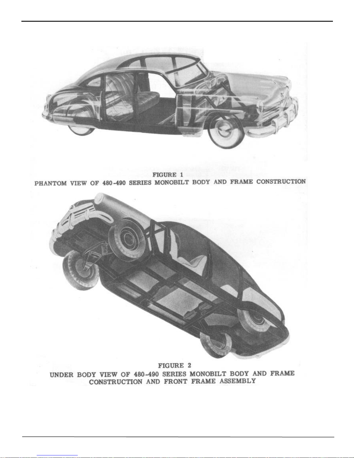
The series 480 and 490 Hudson is built of a completely new principal and design, and is not just another
motor car. The "Monobilt" body and frame construction differs greatly from the conventional motor car
employing separate body and frame units. Naturally being so totally different, a new approach to the repair of
body damage is necessary. These differences, however, do not make the repair job more difficult or more
costly to complete. In many instances the time required on a specific operation is less than that required on
previous models.
Once you are completely familiar with the Monobilt body and frame construction of the 480 and 490
series Hudson, when you have learned the placement of all of the various parts and assemblies and how they
fit together to make the rugged and sturdy Monobuilt all steel unit, then you will go about each job with
complete confidence.
The information contained in this body manual is to be used as a guide for servicing the 480-490 series
Hudson.
The manual has been divided into four parts:
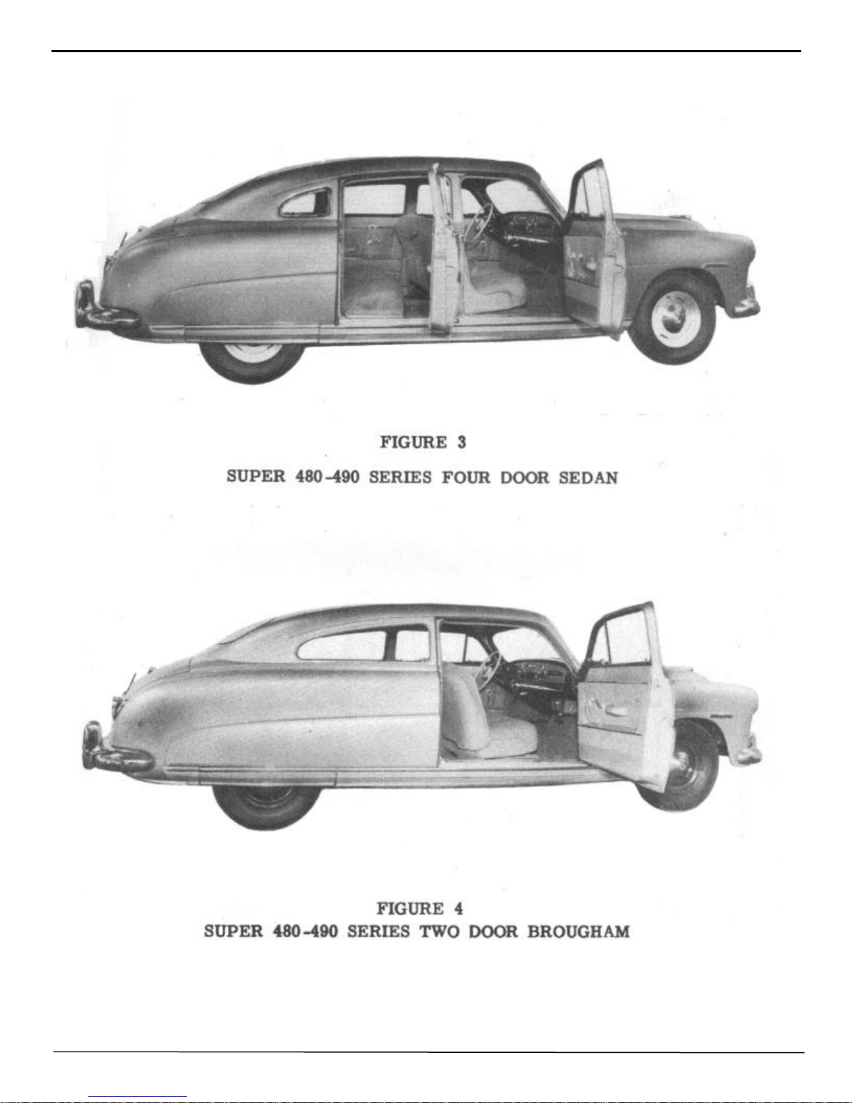
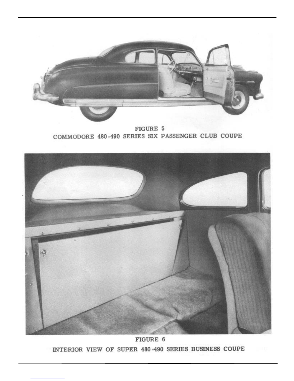
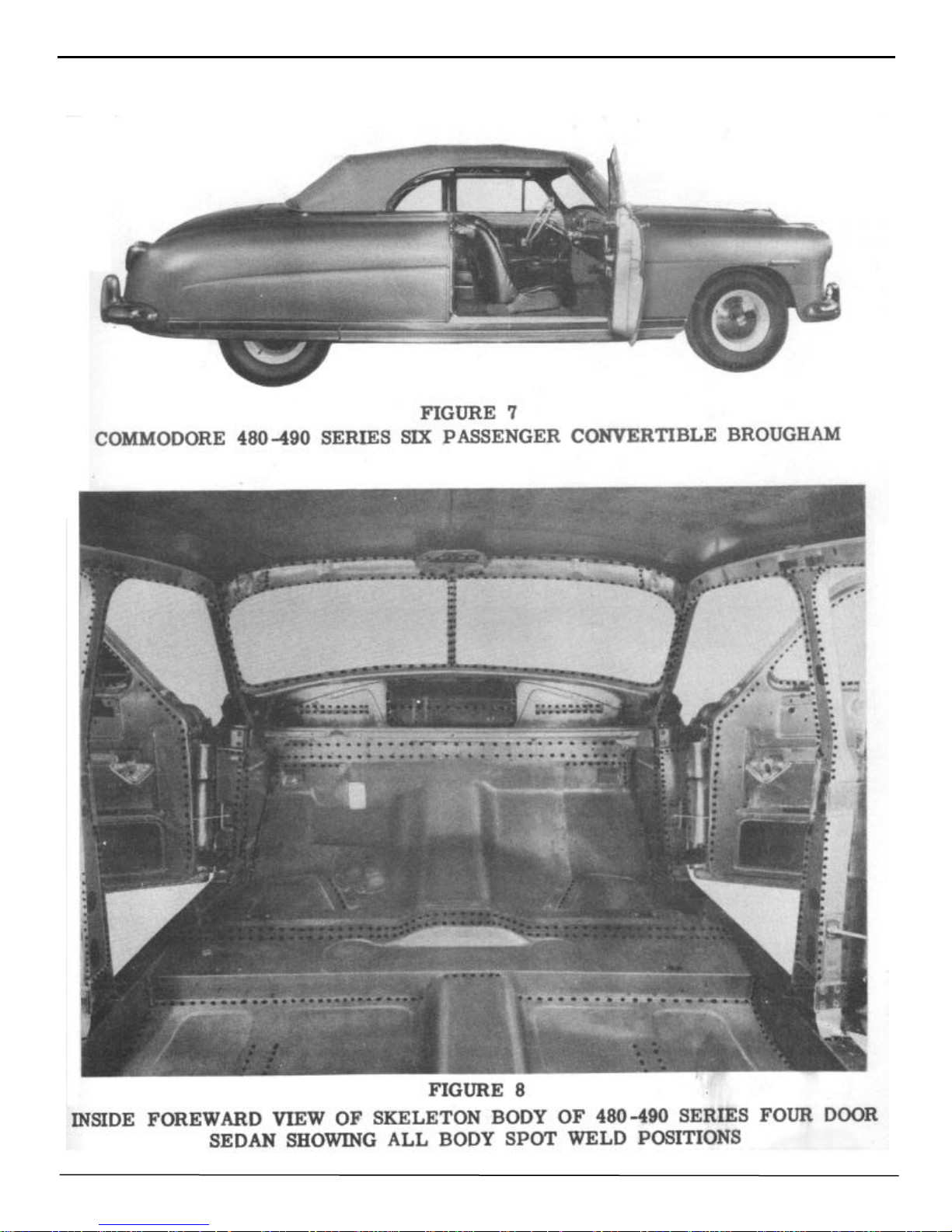
Part one - includes technical information, model designations, body paint color code, estimating and
ordering of repair parts, car serial number identification, and trim material color chart. Illustrated in this
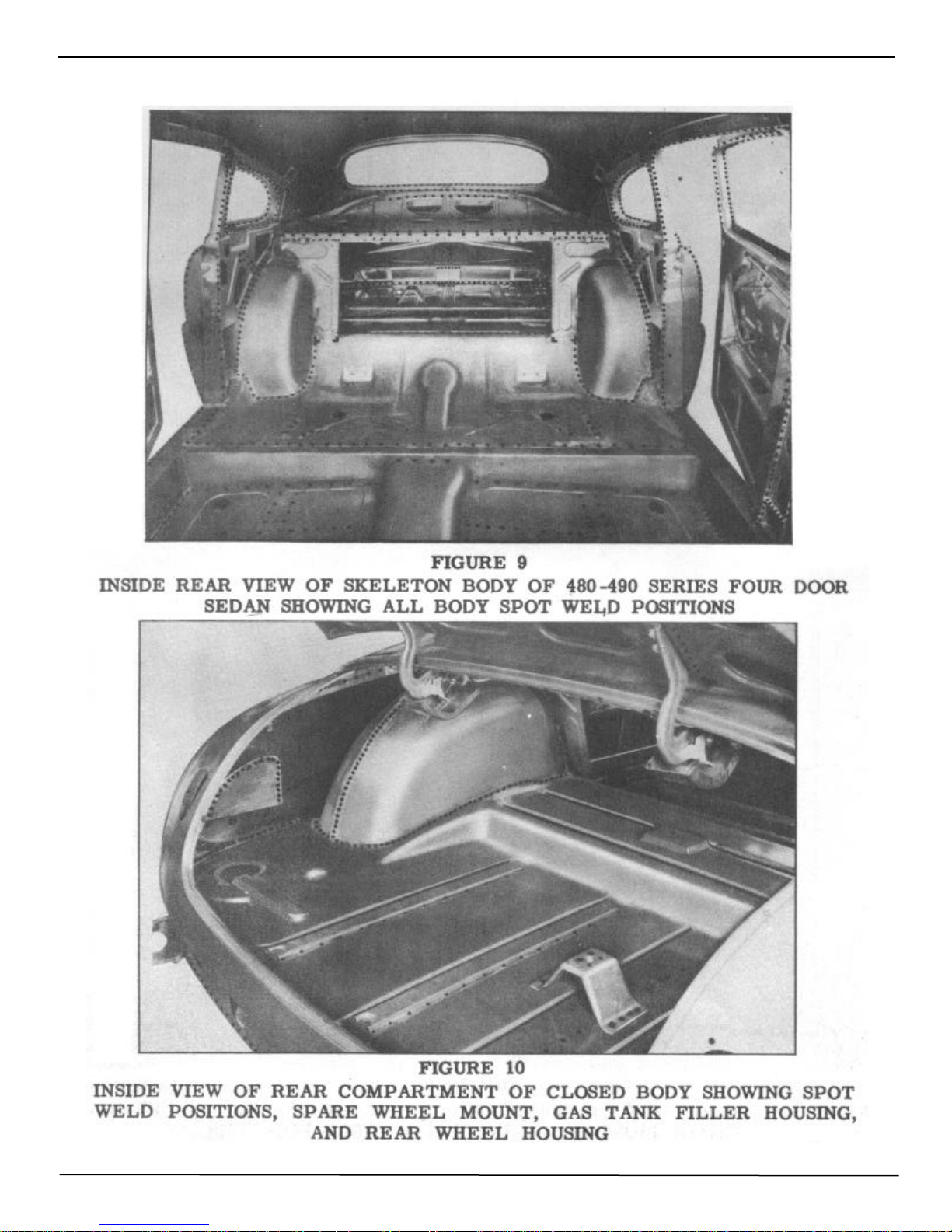
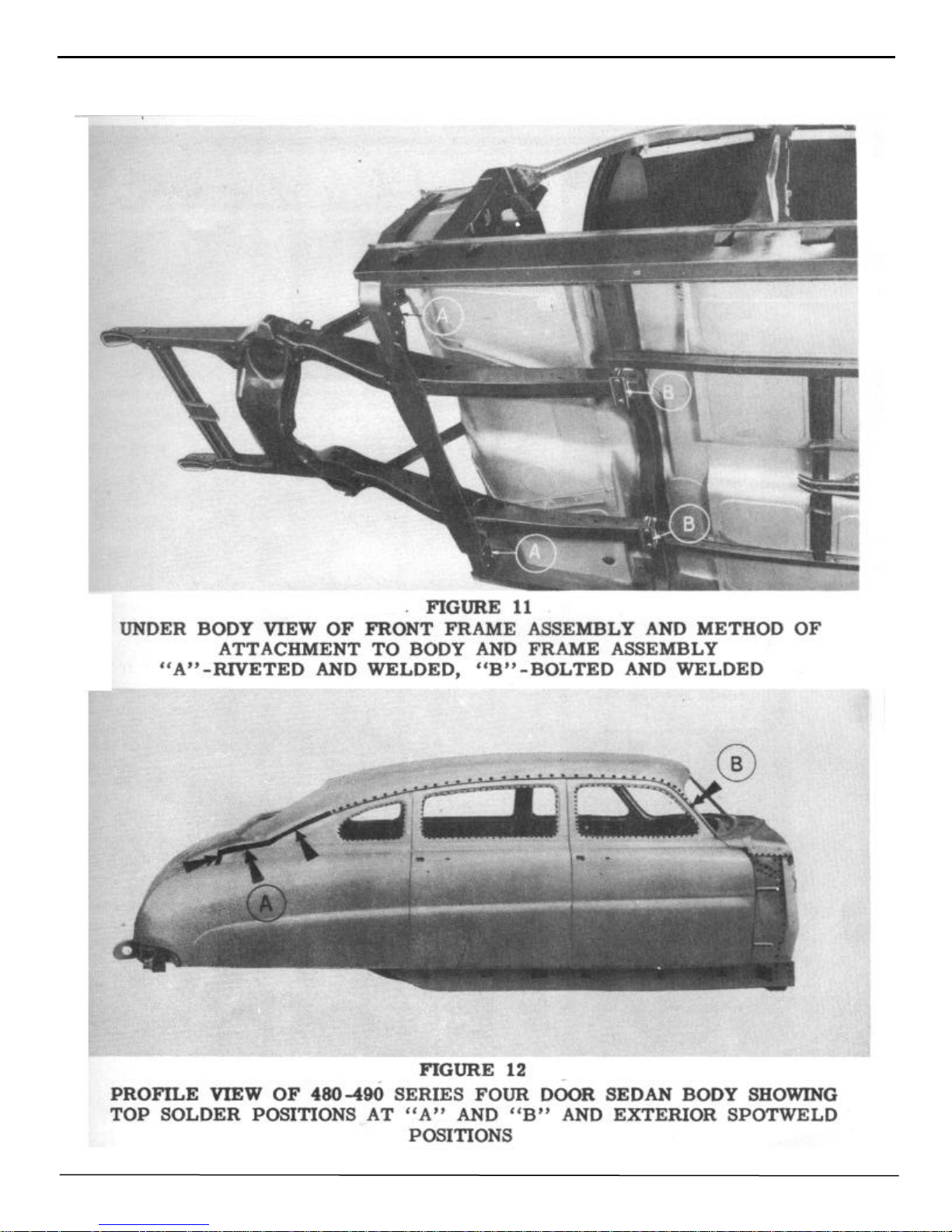
section are the various body types, positions of body welds and top panel soldering.
Part two - includes removal and installation of sheet metal parts: viz., fenders, rocker panels, hood, grille,
rear compartment; also interior hardware, trim, instruments, headlining, door locks, handles, and regulators;
and front wheel alignment.
Part three - includes body repair and metal finishing, consisting of tool application, bumping, dinging,
solder filling, shrinking, fender welding, filing, sanding, and removing minor dents. Part three also includes
body alignment checking, door repairs, and door alignment.
Part four - comprises the convertible 480-490 series, consisting of complete information on repairs of
hydraulic and electrical units, removal and installation of component assemblies and parts, top adjustments,
and trouble shooting.
Illustrations and pages of this manual are numbered consecutively.
An alphabetical index is placed in the front of the manual for easy reference.
A thorough study of the operations and necessary tools and equipment will enable the Hudson Service
dealer to perform reliable service at reasonable cost.

INDEX
III
Adjustment, door striker
folding top
hood
radio
weather control
door window
windshield wiper arms
top control rod
Alignment, body
door
frame
front wheel
rear curtain, convertible
Battery gravity
Bleeding the hydraulic system
Body aligning
Body repair
Breaker, circuit
Brazing
Bumping
Camber
Caster
Cigar lighter
Circuit breaker
Circuit breaker- check, convertible
Cleaning upholstery
Clock
Coil spring sag
Cold shrinking
Construction, body
Color guide
Colors, body
Convertible brougham
Curtain, rear
Cylinder, door lock
Cylinder, hydraulic
Cylinder, solenoid
Dimensions
Dinging
Door aligning
Door lock cylinder
glass front
glass rear
lock
outside handle
remote control
striker plate adjustment
striker plate
trim panel
ventilator wing
ventilator wing regulator
window regulator front
window regulator rear
Page
27,60
74
23
38
40
88
36
74
48,62-64
58
60-61
1,41-43
85
90
94
62
47
32,41,88,91
54
47-54
1,41-43
1,41-42
33
32,41,88,91
91
44
34
43
53,55
50
9,25
3-5
13,67-96
84-86
27,83
69,74-78
77,92-93
2
52,53
58
27,83
31,77
31,77
27,29,83
28-82
30,83
27-60
27
28,31,81,82
30,78
30
28
29
Door lock lubrication
Door straightening
Door trim panel - Convertible .
Door window regulator hydraulic
convertible
cylinder
Elastic metal
Electrical system checks - convertible
Fender, front
rear
Fender and grille side support
Fender stone guard and panel - front
Fender tie panel
Filing
Finish, care of
Fluid, hydraulic
Fluid pressure
Flux
Forging welds
Frame alignment
Front suspension
Fuel gauge
Fuses
Glass, door
quarter window
rear window
windshield
Grille, radiator
radio speaker
Ground, cylinder solenoid . . .
pump motor
Gauge, fuel
rear curtain
temperature
Handle, door
Headlining
Heat shrinking
Hood
Hood adjustment
lock upper support
lock lower support
Hydraulic pump prime
Hydraulic system check - convertible
Hydro-Lectric Motor and pump assy
Hydro-Lectric, service
system
Ignition switch
Instruments
Instrument panel
Insulation
Jacks, body
Lamps
Lock, door
Page
83
59
81
75-77
77
77
47
91
20
19
23
20
24
52,53,57
45
76,90-91, 94
70,76,93
54
57
60
1,41-43
35
41
31,77
31,32
32
26
22
37
77,93
70,71,72
35
85
35
28,82
24-27
53,55
23
23
23
23
94
93
70,72
90
67-96
32
32
32
65
49,51-52
2,33,34
27,29,83

Window operating switches-convertible
IV
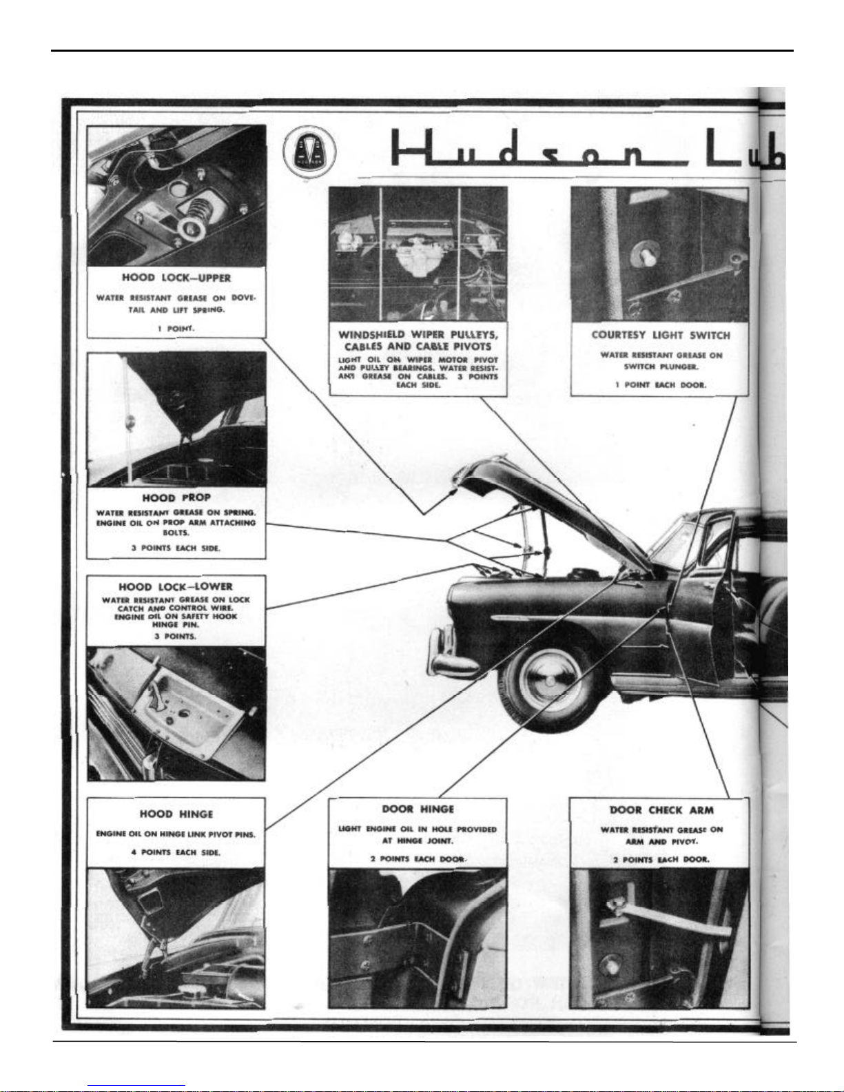
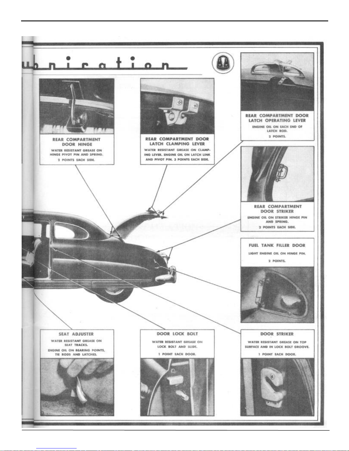
Lubrication, body
hydraulic cylinder
lock
Metal finishing
Model designations
Monobuilt body
Motor, pump
Motor solenoid switch check-convertible
Normalizing
Paddle, solder
Paint
Paint - care of finish
Panel, instrument
switch
trim
Parts, repair
Pivot pin inclination
Pulley adjustment
Pump hydraulic
Quarter trim panel
Quarter window
trim panel
window regulator
Quarter window - convertible
Quenching
Radiator
Radiator grille baffle (upper) .
front splash guard and moulding
grille center bar (upper)
Radiator splash guard moulding
Radiator "U" channel
Radio
Radio - installation
automatic tuning
Rear window
Refilling the hydraulic system convertible
Remote control, door
Regulator, door wing
front door
hydraulic
quarter window
rear door
Resealing
Reservoir, fluid
Rheostat, lamp
Riding height and coil spring sag
Roof bows
Roughing
Sanding
Sealing
Seat cushion front and rear
back, front and rear
Serial numbers
Shrinking - cold
hot
Solder filling
Speedometer
Page
16
75, 77
83
47-58
1
II, 10
68, 69,70-72, 90
92
64
9, 54
3-6,45
45
32,34,37
34
28,31,81,82
6, 19
42
36
70,72,90,94
82
31
31
32, 79
79
54,56
22
22
22
22
23
22
36, 39
36
38
32
94
30, 83
30, 78
28
69,75-78,86,88
32,79
29
64
70,71,90-91
33
43
9, 25
48, 58
53,58
65
82
82
1,6
55
55
52,53,54
34
Spindle pin inclination
Splash guard
Spot weld positions
Springs, front
rear
window regulator
Starter switch
Stone guard
Striker, door
Switch, ignition
light
motor solenoid
starter
top operating
window operating
Technical Information
Temperature gauge
Tie rods
Tools - application of
Tools - body
clip removing
headlining
switch removing
Toe-in
Toe-out
Top adjustment
Top control rod
Top covering installation
Top, folding
Top operating cylinder
Top operating switch check
Top operating valve and switch
Torch soldering
Tramming
Trim material
Trim panels
Trouble shooting
Upholstery cleaning
Upholstery material
Valve, cylinder solenoid
pressure relief
top operating
Weather control
Wedge, hydraulic
Welding
Wheel bearings
Window adjustment
Window lift switch-check-convertible
Window regulator solenoid check
Windshield
Windshield wiper
Windshield wiper control
wiper cable tension
Wing, door ventilator
Wiring
Page
1, 41-42
22, 23
13-15
2 43
2
69, 75, 76
32
20
27, 60
32
32
68, 69, 70, 92
32
72, 73, 90, 91-92
69, 79-81, 88, 91
1
35
1
50
49
78
25
80, 81, 91
1, 41, 43
43
86 87
73, 74, 91
84
68, 70-75, 84, 16
74, 75
91
72, 73, 74, 93
52, 53, 54
62
7
28, 31, 81, 82
95-96
44
7
77, 92-93
70 93
68, 72, 73, 90, 93
39, 41
49
53, 54, 57
1
88 89
91
79, 80
92
26
33
33
36
30, 79
88, 89, 90, 91, 93

BODY MANUAL 1
NOTE: Caster must not vary
more than ½ between sides
Tie Rod End Adjustment (As
seen from right side of car
):
MODEL DESIGNATIONS AND SERIAL NUMBERS
The new Hudson models are produced in the Super and Commodore Series and carry the following designations:
Hudson Super Six Series - Model 481 - 491
BODY TYPES
Brougham
4 Door Sedan
3 Passenger Coupe
Club Coupe
Convertible Brougham
4 Door Sedan
Club Coupe
4 Door Sedan
Club Coupe
4 Door Sedan
Club Coupe
Convertible Brougham
STARTING SERIAL NO’S
481101 - 491101 and up
Hudson Commodore Six Series - Model 482 - 492
482101 - 492101 and up
Hudson Super Eight Series - Model 483 - 493
483101 - 493101 and up
Hudson Commodore Eight Series - Model 484 - 494
484101 - 494101 and up
The car serial number, which is also the engine number, is stamped on a metal plate attached to the right front
door hinge pillar post. In the car numbering system, the first three digits of the serial number indicate the series and
model while the remaining digits represent the actual car number. As the cars leave the production line, they are
numbered in consecutive order, regardless of series or model. As an example, the car built after serial number
491999 would be numbered 4911000 instead of 492000. Code letters or numbers indicating the car paint color
option are stamped on the upper hinge of the right front door.
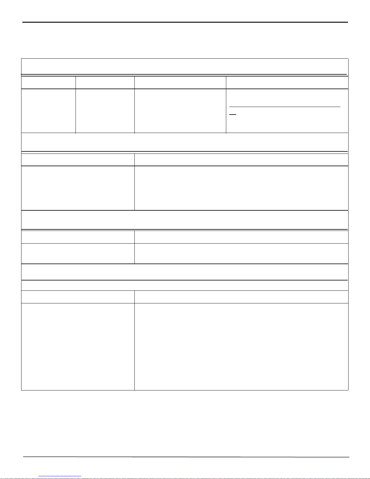
TECHNICAL INFORMATION
FRONT SUSPENSION SIX CYLINDER EIGHT CYLINDER
Type
Camber
Caster
Toe-in
Spindle pin inclination
Spindle pin thrust bearing
Wheel Bearing - Type
End Play
Tie Rod End (Type)
Number of Tie Rods
Independent Coil Springing
1/2° to 1-1/2°
1/2º to 1-1/2°
0" to 1/16"
3° - 36'
Ball
Adjustable tapered roller
.001 to .003
Plain Bearing
2
Independent Coil Springing
1/2º to 1-1/2º
1/2º to 1-1/2 ° sides
0" to 1/16"
3° - 36'
Ball
Adjustable tapered roller
.001 to .003
Plain Bearing
2
To lengthen
To shorten
Turn clockwise
Turn counter-clockwise
Turn clockwise
Turn counter-clockwise

2 BODY MANUAL
FRONT SPRINGS SIX CYLINDER EIGHT CYLINDER
Type
Free Height
Height under curb weight
REAR SPRINGS
Type
Covers
Length and Width
Number leaves
Shackles
Lubricant-Shackles and Leaves
Headlight (Sealed Beam Type)
Hood Light
Parking Light with Direction
Indicator
Tail and Stop Light
License Light
Dome Light-Front
Rear Quarter Lights (2)
Clock
Speedometer
Instrument Cluster
Direction Indicator
Ignition Lock
Courtesy Lights
Fog Light (Sealed Beam)
Spot Light Sealed Beam)
Parking Light
Generator and Oil Indicator
Radio
Headlight Beam Indicator
Coil
16-5/16"
9-9/16"
Semi-elliptic
Covered
Uncovered
Metal
54" - 1-3/4"
8
Silent "U" Threaded
Viscous chassis lube
LAMP BULBS
No.
4030
55
1154
1154
63
87
81
55
55
55
55
55
87
4015-A
4535
63
55
55
55
C. P.
Sealed
2
21-3
21-3
3
15
6
2
2
2
2
2
15
Sealed
Sealed
3
2
2
2
Coil
16-5/16"
9-9/16"
Semi-elliptic
Covered
Uncovered
Metal
54" - 1-3/4"
8
Silent "U" Threaded
Viscous chassis lube
Base
Sealed
Single
Double
Double
Single
Single
Single
Single
Single
Single
Single
Single
Single
Sealed
Sealed
Single
Single
Single
Single
DIMENSIONS (6 Passenger 4 Door Sedan)
Wheel Base
Overall Length
(Including Bumpers and Guards)
Overall Width (Including Fenders)
Tread
Front
Rear
Road Clearance
Front
Rear
Overall Height-Road to Roof
SIX CYLINDER EIGHT CYLINDER
124"
207-1/2"
77"
58-1/2"
55-1/2"
8"
8"
60"
124"
207-1/2"
77"
58-1/2"
55-1/2"
8"
8"
60"
BODY MANUAL 3
1948 HUDSON BODY COLORS
Standard Single Body Colors Option Special Two-Tone Combinations Option
Banner Blue
Jockey Blue
Gallant Gray
Quartermaster Gray
Piedmont Green
Savoy Green
Maroon-Deep
Ruby Red*
Navahoe Bronze
Harness Tan
Ebony Black
* Ruby red is a special body color and is listed above only to complete the two-tone combination
with maroon-deep.
B
M
RR
G
Q
N
H
K
Upper Body Color
J
P
S
Lower Body Color
Upper Body Color
Lower Body Color
Upper Body Color
Lower Body Color
Upper Body Color
Lower Body Color
Upper Body Color
Lower Body Color
SPECIAL SINGLE BODY COLORS
JB
QG
SP
RM
HN
Body Colors Option Option on Models
Ruby Red*
Platinum
RR
CC
481-P - 482 - 483 - 484 Broughams
Sedans, Bus. Coupes, Club Coupes, and
481-P - 482 - 484 Convertible Brougham
ORDERING PAINT OR PAINTED PARTS
When ordering paint or painted parts, special care should be exercised in listing the paint option code and the
paint color or colors. This information is valuable, especially when the automobile has a two-tone color
combination. Always use the charts furnished herein and be sure that every repair order including paints has the
complete, detailed information.
Hudson body colors are pure virgin lacquers. For the maintenance and protection of these high quality finishes
refer to Page 45 of this manual under the heading "Paint - care of finish."
4 BODY MANUAL
CHART No. 1
1949 HUDSON BODY COLORS
Standard Single Body Colors Option Special Two-Tone Combinations Option
Brigantine Blue**
Jersey Blue
Glowing Gray
Queenstown Gray
Piedmont Green**
Savoy Green**
Nomad Bronze**
Holster Tan**
Maroon - Deep**
Ruby Red*
Ebony Black
* Ruby red is a special body color and is listed above only to complete the two-tone combination
with maroon-deep.
**Not available on convertible brougham.
M
RR
G
Q
N
H
K
B
J
P
S
Upper Body Color
Lower Body Color
Upper Body Color
Lower Body Color
Upper Body Color
Lower Body Color
Upper Body Color
Lower Body Color
Upper Body Color
Lower Body Color
SPECIAL SINGLE BODY COLORS
Body Colors Option Option on Models
JB**
KG
SP**
HN**
RM**
Ruby Red*
Platinum
*Refer to Page 5 for 1949 body color option information.
RR
CC
491-P - 492 - 493 - 494 Broughams
Sedans, Bus. Coupes, Club Coupes, and
491-P - 492 - 494 Convertible Brougham
CHART No. 2
1949 HUDSON BODY COLORS
Standard Single Body Colors Option Special Two-Tone Combinations Option
Pacemaker Green Opalescent
Sierra Green Opalescent
Naples Tan Opalescent
Hardwood Tan Opalescent
Gull Gray Opalescent
Quebec Gray Opalescent
Burgundy Maroon Opalescent
Radiant Red Opalescent*
Brazilian Blue Opalescent
Jet Blue Opalescent
Ebony Black
8
10
7
3
2
9
6
16
1
4
5
Upper Body Color
Lower Body Color
Upper Body Color
Lower Body Color
Upper Body Color
Lower Body Color
Upper Body Color
Lower Body Color
Upper Body Color
Lower Body Color
14
11
13
15
12
SPECIAL SINGLE BODY COLORS
Body Color Option Option on Models
BODY MANUAL 5
Radiant Red Opalescent
Gray Gold (light) Opalescent
16
17
491P - 492 - 493 - 494 Broughams, Sedans,
Bus. Coupes, Club Coupes, and 492-P 492 - 494 Convertible Brougham.
1949 BODY COLOR OPTION INFORMATION
It will be noted that the 490 Series Hudson has two methods of paint option identification. On approximately the first 100,000
490 Series cars an ALPHABETICAL paint option was stamped into the right hand front door upper hinge, body half. (See 1949
Body Color Chart No. 1)
Body color Chart No.2 lists the new body colors and the NUMERICAL options used on the 490 Series Hudson after
approximately the first 100,000 cars. This numerical paint option is also stamped into the body half of the right hand front door
upper hinge.
EXAMPLE: (Chart No. 1)
Single Body Color Option
Brigantine Blue
Jersey Blue
Two-Tone Combination
B
J
Brigantine Blue
Jersey Blue JB
Option
Either brigantine blue or jersey blue may be used as an all over body color in which case a single "B" or "J" will
be stamped into the right hand front door upper hinge. When both brigantine blue and jersey blue are used together as a two-tone combination, the letters "JB" will be stamped into the right hand front door upper hinge.
EXAMPLE: (Chart No. 2)
Single Body Color Option
Pacemaker Green Opalescent
Sierra Green Opalescent
The application of the numerical option colors is handled in the same manner as is the alphabetical
options outlined above.
8
10
Two-Tone Combination
Pacemaker Green Opalescent
Sierra Green Opalescent 14
Option

6 BODY MANUAL
jobs, or lose money on them if you do get them. A successful future for your business depends upon the correctness
In the event a new NUMERICAL body color is used in two-tone combination with an old ALPHABETICAL
body color, the option stamping will appear as below:
Brazilian Blue Opalescent (New) 1
Jersey Blue (Old) J
This will be the only occasion when both SINGLE body color options used in two- tone combinations will appear stamped in the right hand front door upper hinge.
ESTIMATING AND ORDERING OF REPAIR PARTS
Like any other automobile repair operation, the damaged body must have a preliminary survey to determine the
over all extent of the damage. When the survey has been completed, the answer to three vital questions will be necessary before work can begin.
Can you repair the damage?
How much will it cost?
How soon can it be ready?
The accuracy of your answers to these vital questions determines whether or not your shop gets the repair job
and whether or not you make any profit on the job if you do get it. Guessing won't do----that way you lose repair
with which you answer those three important questions.
The service departments of all Hudson distributors and dealers are supplied with current service parts catalogues
from which a listing, by PROPER NAME and PART NUMBER, of the parts required can be formulated.
From this list, which includes the proper car IDENTIFICATION NUMBER taken from the car serial number
plate, the Hudson parts manager will be able to arrive at an estimate of the cost of the job, from which a definite decision can be made before ordering the necessary parts.
To be certain that the proper repair parts are received with the least possible delay, it is important that the following car identification be included with each repair order.
CAR SERIAL NUMBER PAINT CODE MARKINGS *
*The paint color code is the alphabetical stamping on the right hand front door upper hinge, body half.
By supplying this information you are enabling those who make up the repair parts order to include the correct
parts. Thus delays, such as would be encountered upon the receipt of the wrong parts, are eliminated, and considerable time is saved.
BODY MANUAL 7
DESCRIPTION OF PARTS
The correct description of the parts as they are listed in the service parts catalogue is all-important, as is the location of the part on the automobile.
For example fenders, doors, windshield glass, and rocker panels should be referred to as left or right, front or
rear.
ORDERING TRIM MATERIAL
The following chart on the Hudson upholstery options in relation to paint options will prove helpful when the
need arises to order upholstery material.
The paint option chart is also included and will serve to clarify the alphabetical paint code stamping on the upper
hinge of the right hand front door and as a cross reference guide when ordering upholstery materials. See Page 4.
CHART No. 3
Use This Chart In Conjunction With Chart No. 1, Paint Option Codes
1948 COMMODORE SERIES UPHOLSTERY OPTIONS
Option Model Upholstery Color Standard with Body Colors
W-1
W-2
482-484
482-484
Tan Broadcloth
Gray Broadcloth
H,K,M,N,P,RR,S,HN,SP,RM
B,CC,G,J,K,Q,JB,QG
1949 COMMODORE SERIES - EXCEPT CONVERTIBLES
W-1
W-2
W-3
W-4
492-494
492-494
492-494
492-494
Tan Broadcloth
Gray Broadcloth
Brown Cloth and
Maroon Leather Trim
Gray Cloth and
Maroon Leather Trim
H,M,N,P,RR,S,HN,SP, and RM
B,CC,G,J,K,Q,JB, and QG
(Optional)
(Optional)
CONVERTIBLE BROUGHAM UPHOLSTERY
Models Color
491, 492, 494 Maroon Leather antique grain is standard
Models Color
481, 491, 483, 493 Bedford Cord cloth, Blue-Green shade, is
SUPER SERIES UPHOLSTERY
standard
8 BODY MANUAL
CHART No. 4
Use this chart in conjunction with chart No. 2, 1949 "Paint Option Codes"
COMMODORE SERIES - EXCEPT CONVERTIBLES
Option Model Upholstery Color Standard with Body Colors
W-1
W-2
492-494
492-494
Tan Cloth Trim
Gray Cloth Trim
CONVERTIBLE BROUGHAM UPHOLSTERY
Models Models
491-492-494 Maroon full leather trim is standard.
Brown cloth and maroon leather
combination trim - optional.
Gray cloth and maroon leather
combination trim - optional.
SUPER SERIES - EXCEPT CONVERTIBLES
Model Color
491, 492, 494 Gray cloth trim is standard
Gray leather trim - optional
M-6, RM-15, RR-16 and CC-17
H-3, N-7, HN-11, P-8, S-10, SP14
B-1, G-2, J-4, Q-9, JB-12, QG-13
and K-5
LEATHER TRIM
ALL BROUGHAMS, SEDANS, BUSINESS COUPES, AND CLUB COUPES
Material Color
Russet Leather Trim
Gray Leather Trim
Maroon Leather Trim
Hudson upholstery materials are of the finest broadcloth and Bedford Cord available, however, this fact does not
create immunity to spots and stains. For details on the removal of spots and stains, please refer to Page 44 of this
manual under the heading "General Information on Appearance."
Standard with body colors S-10, P-8, SP-14, H-3, HN-11,
M-6, RR-16, RM-15, and CC-17.
Optional with body colors B-1, G-2, J-4, Q-9, JB-12,
QG-13, and K-5
Standard with body colors B-1, G-2, J-4, Q-9, JB-12,
QG-13, and K-13. Optional with S-10, P-8, SP-14, H-3,
HN-11, M-6, RR-16, RM 15, and CC-17
Optional
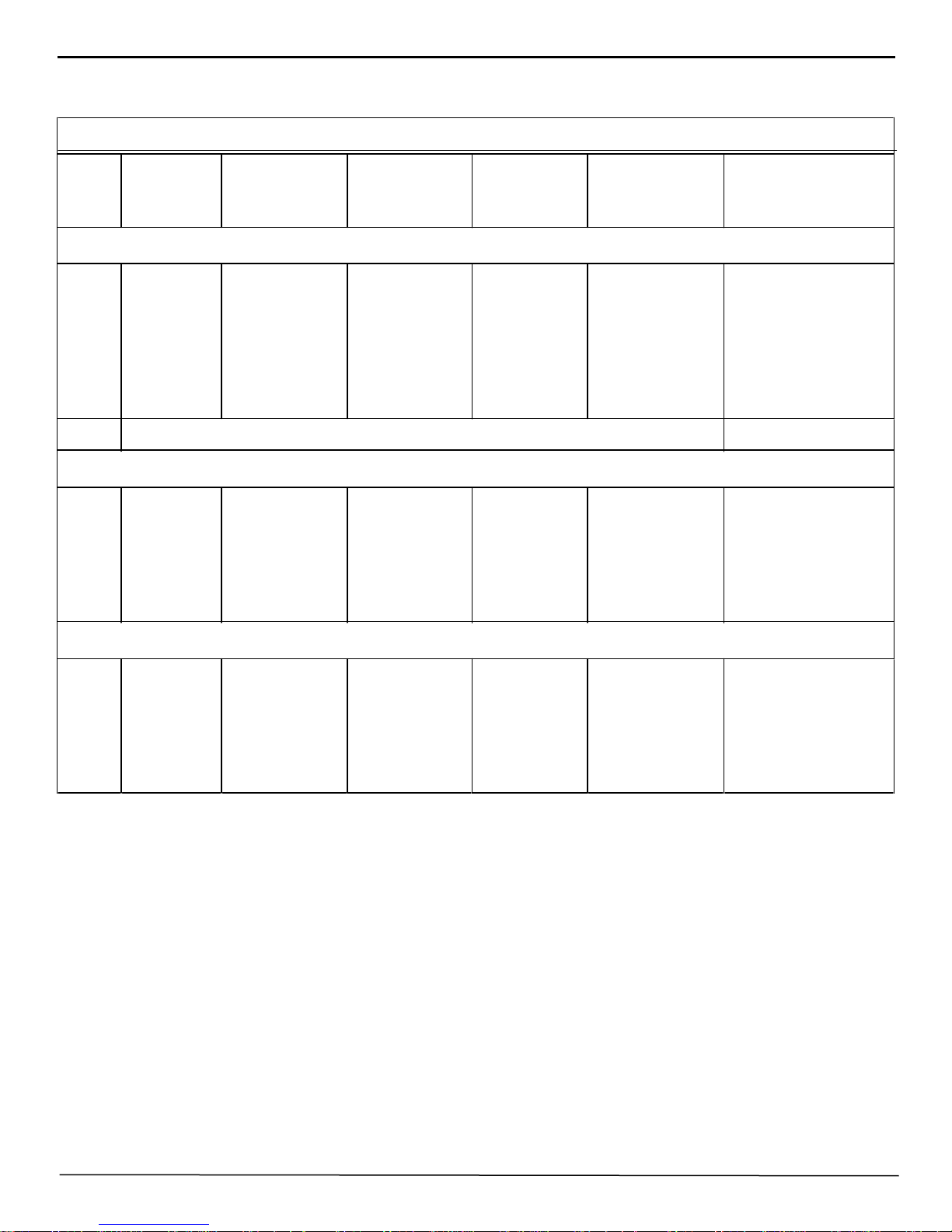
CHART No. 5
BODY MANUAL 9
Bow
No.
1
2
3
4
5
6
1
2
3
4
5
6
Part
Number
Up to and
Including
Serial No.
ROOF BOW COLOR
Color
GUIDE
Part
Number
4 DOOR SEDAN
210761
210762
210763
210764
210765
210766
*Except car numbers 115221 thru 115722 inclusive
483115172
"
"
"
"
"
Black
Light Gray
Tan
Light Blue
Dark Red
Pink
216220
216221
216222
215223
216224
216225
2 DOOR BROUGHAM
210761
210768
210769
210774
210775
210776
4912700
"
"
"
"
"
Black
Light Gray
Tan
Light Blue
Dark Red
Pink
216220
215226
216227
216228
216229
216230
Serial No.
and upward Color
48311517*
"
"
"
"
"
4912701
"
"
"
"
"
Black
Light Green
Yellow
Light Red
Dark Green
Dark Brown
Black
Light Gray
Cream
Light Blue
Dark Red
Pink
COUPE AND CLUB COUPE
1
2
3
4
5
6
210751
210768
210769
212954
212955
212956
4912700
"
"
"
"
"
Black
Light Gray
Tan
Silver
Gold
Dark Gray
216220
216226
210769
216231
215232
212956
4912701
"
491127
4912701
"
4912701
Black
Light Gray
Silver
Gold
Gold
10 BODY MANUAL
BODY MANUAL 11
12 BODY MANUAL
BODY MANUAL 13
14 BODY MANUAL
BODY MANUAL 15
16 BODY MANUAL
Figure 13
BODY MANUAL 17

18 BODY MANUAL
REFERENCE
Source of
Information
Date Subject
BODY MANUAL 19
REMOVAL AND CARE OF
PARTS
With most damaged bodies, there are parts that
have to be removed to facilitate the repair of the
damaged sections. These parts, whether they are
damaged or not, should be kept in some suitable
container or storage bin to prevent further damage
and eliminate the possibility of parts becoming lost.
Where severe body damage is encountered, it is
best to remove body trim parts, all of which are
easily removed, and store them in a clean, dry
place. By approaching the actual repair job in this
manner, more freedom and better visibility during
the repair operation is possible. Considerable time.
and patience, too, is thus saved in the aligning
operation and in the effective placing of body jacks.
With the body trim parts safely stored out of the
way, the possibility of burning, tearing, or soiling
of upholstered parts is negligible.
8. Remove rear bumper extension at side of fender.
9. Pry off fender panel lower moulding.
10. Remove the two self tapping screws attaching rear
fender panel and moulding retainers to the rocker panel.
11. Remove the 7 bolts and nuts attaching the fender
panel and moulding retainers to the rocker panel.
12. Lift off rear fender. See Figure 14.
REMOVAL & INSTALLATION
PROCEDURES
REAR FENDER
REMOVAL:
1, Remove rear wheel cover and rod assembly.
2. Remove rear seat cushion and remove the end
section of the rear seat back from same side from
whlch fender is to be removed.
3. Remove rear quarter window garnish moulding
and the valance reveal moulding.
4. Remove rear quarter inside trim panel.
5. Remove 3 Phillips head screws and two self
tapping screws at door pillar post.
NOTE: On Broughams and Coupes it is necessary to remove the rear quarter window to
allow removal of the three fender attaching
screws located behind the glass. See "Quarter
Window Glass Removal," Page No. 31.
FIGURE 14
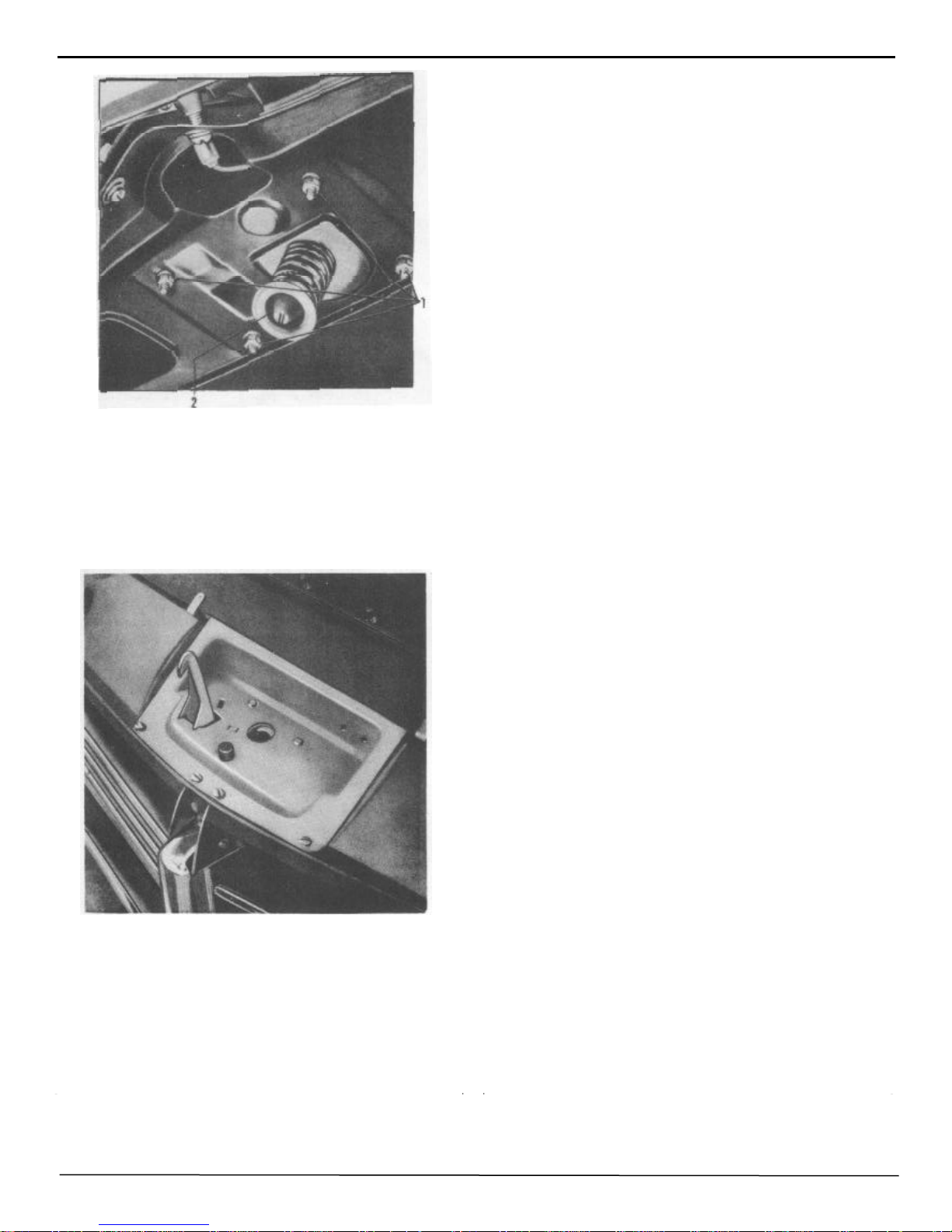
INSTALLATION:
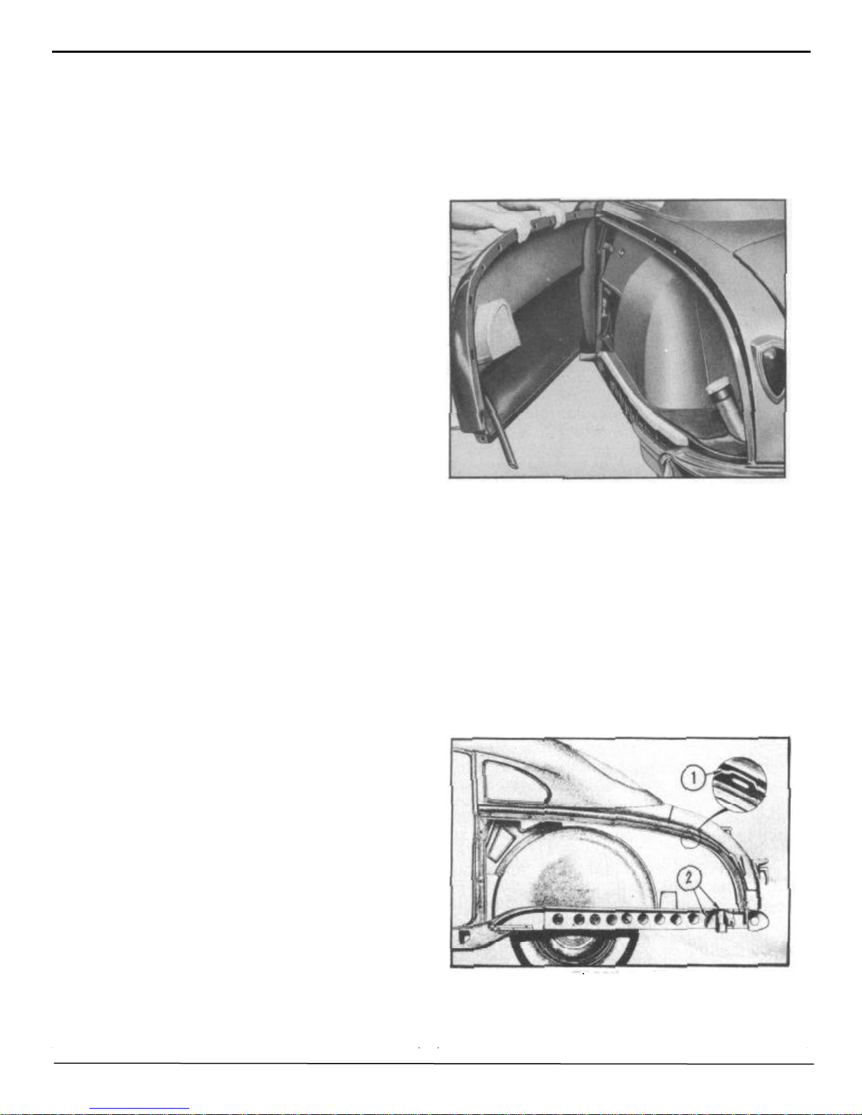
NOTE: Before installing rear fender apply a bead of
Permagum No. 576, Part No. 175356 Sealer, starting
from base of rear door hinge pillar and crossing
quarter panel flange to frame at rear and to area at
2 as shown in Figure 15. Care must be taken to
assure that the bead of sealer is unbroken and does
not cross any fender attaching bolt holes.
6. Remove the spare tire from rear compartment to
permit better accessibility.
7. Remove 7 screws inside rear compartment
which fasten fender to rear quarter panel.
FIGURE 15
1. Align fender at door hinge pillar and install attaching
screws. DO NOT TIGHTEN.
20 BODY MANUAL
2. Attach all upper bolts at quarter panel flange before
attaching fender to rocker panel. DO NOT TIGHTEN.
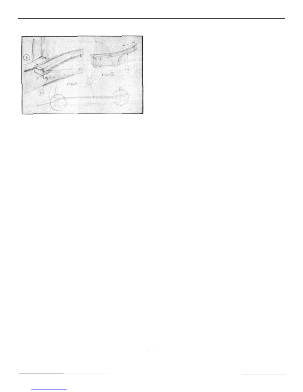
FIGURE 16
3. Install rear fender seal flush with frame flange,
raising the front end 1/8" to interfere with rocker panel
filler, Figure 16, No. 1 and No. 2. Cement seal tightly
and allow approximately 6" from the end of the seal to
remain loose until the fender is completely installed,
No. 4, Figure 16. Then cement seal securely to frame
flange, No. 3, and fender. TIGHTEN ALL ATTACHING BOLTS AND SCREWS SECURELY.
FRONT FENDER
9. Remove moulding and 4 self-tapping screws
attaching fender and moulding clips to front rocker
panel.
10. Remove kick pad in the front seat compartment
at the dash panel.
11. Remove the screw attaching the door opening
belt weatherstrip to fender and front cowl panel.
12. Remove the 4 bolts from behind the kick pad
which attach the fender to the dash panel and front
hinge pillar.
13. Lift off front fender.
14. Remove all trim and useable parts from damaged
fender and install on new fender.
INSTALLATION :
1. With help of an assistant, align fender at cowl
panel and attach screws at kick panel opening and
front door hinge pillar.
2. Attach fender to radiator baffle side shield, fender
side dust shield, and radiator splash guard.
3. Reverse procedure of removal on balance of installation.
NOTE: Reseal fender at cowl panel and at belt
moulding with dolphinite sealer No. 2465,
REMOVAL:
1. Raise hood and disconnect headlight wires at junction block on radiator support.
2. Remove headlight rim (3 Phillips head screws) and
remove the headlight housing (4 screws).
3. Remove the attaching bolts from the fender and side
dust shield.
4. Remove two bolts attaching fender tie panel and
hood lock lower support to fender.
5. Remove the upper hood prop bolt and allow hood
prop to be removed with fender side dust shield. Support hood during this operation.
6. Raise car and remove front wheel.
7. Remove 3 bolts attaching fender to radiator baffle
side shield.
8. Remove 3 bolts attaching fender to lower radiator
splash guard.
NOTE: Front fender front extension is spot welded
to the fender and will have to be removed with the
fender.
Part No. 175367. If necessary to replace the weatherstrip, proceed as follows:
A. Apply a coating of rubber cement to the surfaces
of the front pillar face and the belt weatherstrip.
B. Press weatherstrip into position then insert and
tighten attaching screws.
FRONT FENDER STONE GUARD
AND PANEL ASSEMBLY
REMOVAL:
1. Remove 4 bolts attaching stone guard and panel
to front quarter dash panel under the fender, 2 bolts
under rubber pad, and one located to the left of hood
hinge.
2. Remove 3 Phillips head screws and speed nuts at
dust shield extension rubber shield.
3. Remove the panel and stone guard.
INSTALLATION:
Reverse procedure of removal.
BODY MANUAL 21
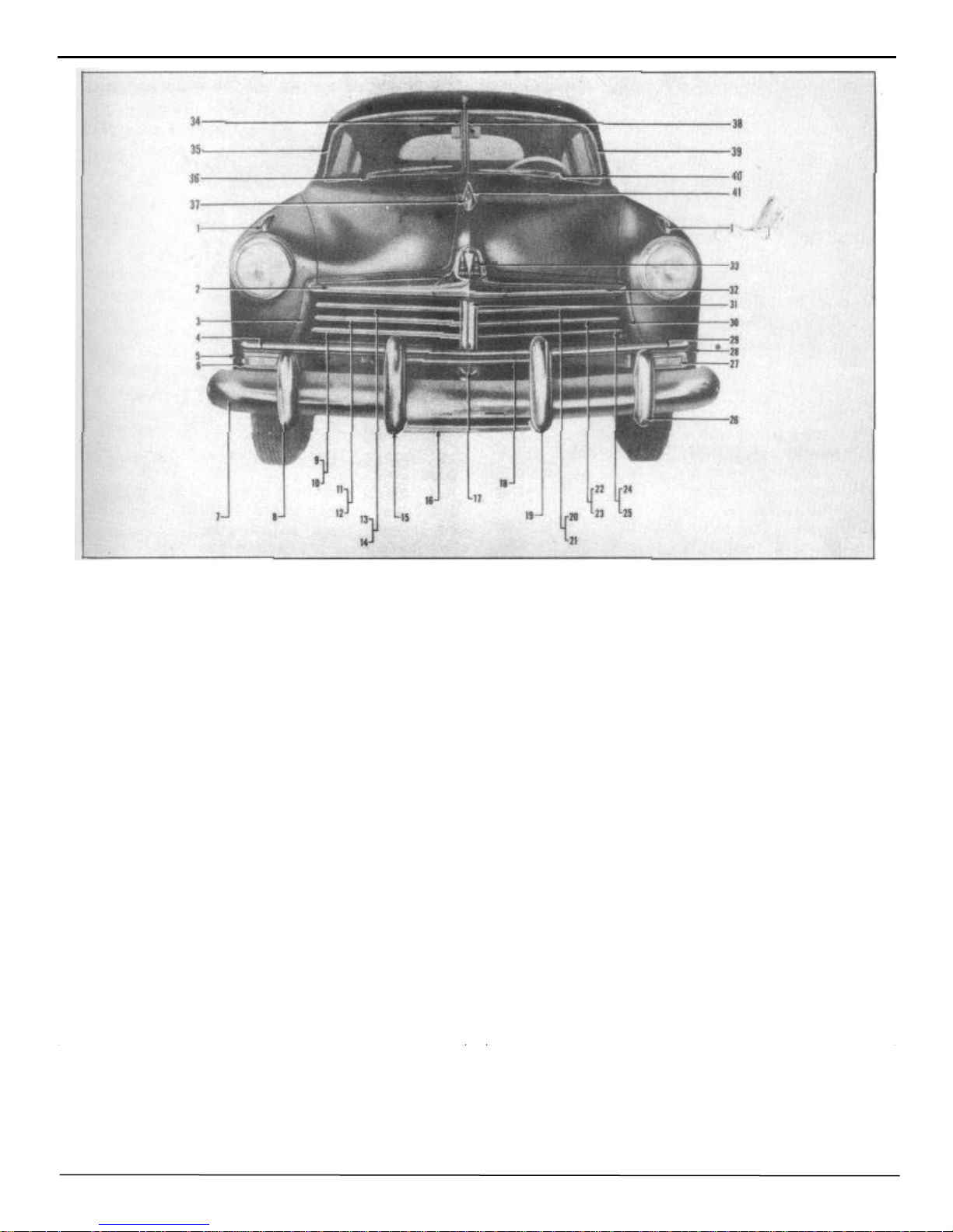
1. Front fender ornament.
2. Hood louver (R.H.)
3. Radiator grille baffle side support (R.H.)
4. Front splash guard moulding
5. Front fender extension assembly (front R.H.)
6. Parking light assembly
7. Front bumper impact bar
8. Front bumper guard (outer R.H.)
9. Radiator grille moulding (lower R.H.)
10. Radiator grille baffle (lower R.H.
11. Radiator grille moulding ( center R. H.)
12. Radiator grille baffle (center R.H. )
13. Radiator grille moulding (upper R.H.)
14. Radiator grille baffle (upper R.H.)
15. Front bumper guard assembly (inner R.H.
16. Front bumper license guard (lower)
17. Radiator grille center bar (lower)
18. Front bumper license guard (upper)
19. Front bumper guard assembly (inner L.H.)
20. Radiator grille moulding (upper L.H.)
21. Radiator grille baffle (upper L.H.)
FIGURE 17
22. Radiator grille moulding (center L.H.)
23. Radiator grille baffle (center L.H.
24. Radiator grille moulding (lower L.H.)
25. Radiator grille baffle (lower L.H.)
26. Front bumper guard (outer L.H.)
27. Parking light assembly
28. Front fender extension assembly (front L.H.)
29. Front splash guard moulding
30. Radiator grille baffle side support (L. H.)
31. Radiator grille center bar
32. Hood louver (L.H.)
33. Hood front ornament assembly
34. Center windshield reveal moulding ( R. H.)
35. Windshield reveal moulding (R.H.)
36. Pulley housing and cable assembly ( R. H.)
37. Hood crest assembly
38. Center windshield reveal moulding
(L. H.)
39. Windshield reveal moulding (L.H.
40. Pulley housing and cable assembly (L.H.)
41. Hood crest ornament.

22 BODY MANUAL
RADIATOR
REMOVAL:
1. Drain radiator and disconnect hoses.
2. Remove two sheet metal screws attaching deflector shield
to fender tie panel.
3. Remove headlight wiring from retaining clips at the front
of radiator.
4. Remove 4 hex head bolts attaching radiator to "U" channel
and remove radiator.
INSTALLATION:
Reverse procedure of removal.
RADIATOR "U" CHANNEL WITH
RADIATOR REMOVED
REMOVAL:
1. Remove headlight junction blocks; leave wires attached.
2. Remove two attaching bolts (each side) from radiator
mounting channel to fender.
3. Remove attaching bolts from mounting channel to fender
tie panel.
4. Remove the bolt attaching the bottom of mounting channel
to frame front cross-member. Remove channel from car.
INSTALLATION:
Reverse procedure of removal.
separately.
1. Remove complete front bumper assembly.
2. Remove three bolts at each side attaching splash
guard to radiator grille panel.
3. Remove bolt at grille lower center bar and the bolt
attaching center plate to right and left hand splash guard.
4. Slide splash guard out.
INSTALLATION:
Reverse procedure of removal.
RADIATOR FRONT SPLASH
GUARD AND MOULDING
REMOVAL:
1. Remove front bumper center grille guard.
2. Remove one bolt (each side) attaching front splash
guard (center) to front fender and lower splash guard.
3. Remove two brass nuts and clips (each side) under
fender attaching fender to splash guard moulding.
4. Remove bolt attaching splash guard to grille lower
center bar and remove splash guard.
INSTALLATION:
RADIATOR GRILLE BAFFLE
(UPPER)
(Right or Left)
REMOVAL:
1. Remove center support bar moulding.
2. Remove screw at front and rear of center bar.
3. Remove one screw from under fender and one screw at
grille baffle side supports. Remove baffle from car.
INSTALLATION:
Reverse procedure of removal.
RADIATOR SPLASH GUARD
(Right or Left)
REMOVAL:
NOTE: The splash guard consists of two pieces joined at
center support. Either right or left side may be removed
Reverse procedure of removal.
RADIATOR GRILLE CENTER BAR
(UPPER)
REMOVAL:
1. Remove two screws and remove the center bar
support moulding.
2. Remove bolts attaching grille baffles to center bar.
3. Remove two bolts attaching center bar to fender tie
panel and to front splash guard.
4. Remove center support and splash guard center plate.
Remove bar from car.
INSTALLATION:
Reverse procedure of removal.
FENDER AND GRILLE SIDE
SUPPORT
(Right or Left Hand)
REMOVAL:
1. Remove the screws attaching the radiator grille baffles
to side and center support. Remove baffles.
2. Remove five bolts under fender attaching the side
panel to fender.
3. Remove the three bolts, nuts, and shakeproof washers
attaching the side support to the radiator mounting channel.
4. Remove three bolts, nuts, and shake- proof washers
attaching the side support to the lower front splash guard.
5. Remove the front splash guard and moulding and
remove the side support from the car.
BODY MANUAL 23
INSTALLATION:
Reverse procedure of removal.
RADIATOR SPLASH GUARD
REMOVAL:
1. Remove two brass nuts and clips (each side) under
fender attaching moulding to front fender lower extension.
2. Pry off moulding with a screwdriver. Use care if
moulding is to be used again.
INSTALLATION:
Snap moulding into place and attach to fender in reverse
procedure of removal.
ENGINE HOOD
REMOVAL:
FIGURE 18
HOOD ADJUSTMENT
1. Loosen the two bolts, ( 9 and 10), which attach the hood
hinge to the cowl just enough to allow for backward or
forward movement.
2. Loosen screws (7 and 8) attaching hinge arm to hood,
(each side).
NOTE: Forward and backward adjustments and up
and down adjustments can now be made at the rear of
the hood. Up or down adjustments at the front of the
hood can be made by raising or lowering the three
rubber bumpers mounted on the front fender tie panel
and adjusting the spring retainer bolt mounted on the
hood lock upper support.
3. After all adjustments have been made, tighten all bolts
and lock nuts securely.
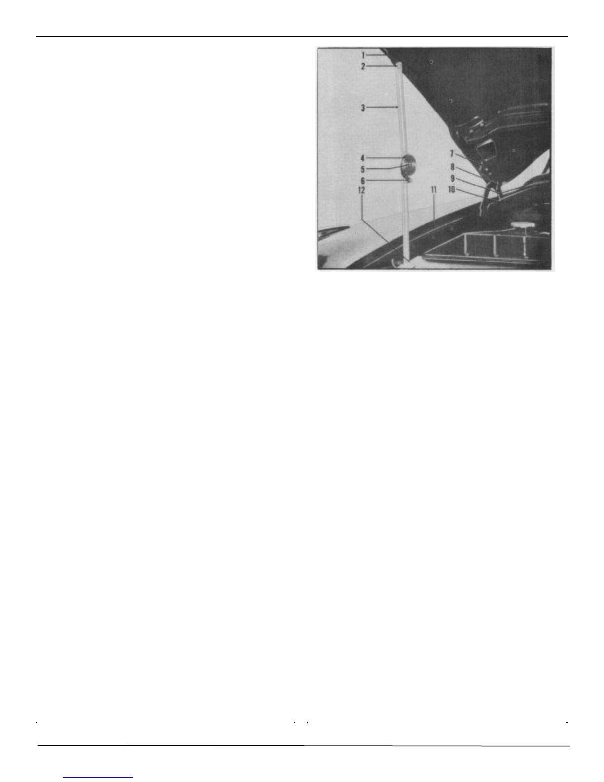
HOOD LOCK UPPER SUPPORT
1. Raise and place prop under front of hood (1), Figure
18.
2. Remove two hood prop bolts ( 2), (one on each side).
Hood props ( 3) remain attached to fender side dust
shields ( 11).
3. Remove the two hood hinge bolts, (7 and 8), from each
side at rear of hood.
4. With a helper, remove hood from car.
INSTALLATION:
Reverse procedure of removal and adjust at hood hinge
bolts.
REMOVAL:
1. With a screwdriver remove the spring retainer bolt (2)
from the attaching nut and remove retainer and spring,
Figure 19.
2. Remove the four attaching nuts and washers ( 1) from
lock support plate. 3. Remove the two sheet metal screws
from bracket at rear of assembly and slide assembly to one
side and remove.
INSTALLATION:
Reverse procedure of removal. Adjust locking spring by
turning slotted retainer assembly to left or right.
24 BODY MANUAL
FIGURE 19
HOOD LOCK LOWER SUPPORT
FENDER TIE PANEL AND HOOD
LOCK LOWER SUPPORT
REMOVAL:
1. Raise hood and disconnect hood lock control wire.
2. Remove two bolts (each side) attaching fender tie
panel and hood lock support to fender bracket.
3. Remove two bolts attaching the fender tie panel and
hood lock support to radiator mounting channel.
4. Remove two bolts attaching fender tie panel to the
front fender skirt.
5. Removing one bolt attaching hood lock support to
radiator grille center support and remove the support
assembly from the car.
INSTALLATION:
Reverse procedure of removal.
REMOVAL:
1. Disconnect flood lock control wire.
2. Remove 4 bolts attaching hood lock lower support to
fender tie panel and remove lower support from car.
FIGURE 20
INSTALLATION:
Reverse procedure of removal. Lock hood control wire
securely and apply water resistant grease to hood lock
release catch.
HEADLINING
Preparatory to headlining removal, remove the following trim parts:
A Sun visors
B Rear view mirror
C Front dome lamp lens assembly
D Upper and lower windshield garnish moulding
E Windshield inside center trim bar
F Windshield retainers
G Windshield glass
H Rear seat cushion, back rests, and center arm rest
I Rear window
J Rear package shelf
K Rear quarter window garnish mouldings
L Rear dome lamp lens assembly
NOTE: HANDS MUST BE CLEAN AT ALL
TIMES WHEN WORKING ON THE INTERIOR
TRIM OF A BODY.
REMOVAL:
1. Remove upholsterer's tacks from around rear window
opening and rear quarter window openings and the
cardboard tacking strips at the extreme rear edge of the
headlining on the package shelf. Pull headlining loose
from cement.
 Loading...