

Hudson 1953 Jet, 1953 Super Jet Mechanical Procedure Manual


FOREWORD
I
This edition of the Mechanical Procedure Manual
will serve as a guide and reference for Hudson servicemen in the proper servicing of Hudson Jet and Super Jet
models.
available from our service tool source, the Kent-.
Moore Organization, Inc., 5-105 General Motors
Building, Detroit 2, Michigan, with whom order
should be placed directly by Distributors and
Dealers.
The data contained in this Manual includes information covering specifications, adjustments and detailed operations involved in maintenance an d repair
procedures. The operations listed herein are predicated
on the use of special service tools developed for the
purpose where necessary and with the work done by
mechanics of average ability.
The Hudson Service Merchandiser is published each month by the Service Department to
keep servicemen supplied with up-to-date information including suggestions and short cuts received from the Field, dealing with the servicing
of Hudson cars. Read this publication regularly
and make full use of the help it affords.
The special service tools illustrated or referred to
in this book are indispensable to good workmanship
and in meeting standard flat rate times. They have been
developed by and are
For easy reference, the Index at the front of the
book is made up of sections in alphabetical order
and with each section alphabetically arranged.
ALPHABETICAL INDEX
Group Page Group Page
BRAKES 136-143 COOLING SYSTEM 53-59
Adjustment-Brakes
Bleeding Brake Lines
Brake Fluid
Brake-Front
Brake Pedal
Brake -Rear
Construction
Lubrication
Master Cylinder
Parking Brake
Specifications
Trouble Shooting
Wheel Cylinder-Front
Wheel Cylinder-Rear
CLUTCH
Assembly-Clutch
Construction
Disassembly-Clutch
Installation-Clutch
Pedal Adjustment
Release Bearing
Removal-Clutch
Flywheel
Operation of Clutch
Release Lever Adjustment
Specifications
142
141
141
140
142
140-141
136
143
136-138
136,142
136
143
139
139-140
72-80
78
72
76-78
80
72
79
76
78
72
78
72
Anti-Freeze Chart
Anti-Freeze Solution
Cooling System Diagnosis
Draining System
Fan Belt Adjustment
Inhibitor
Radiator
Reverse Flushing
Temperature Gauge
Thermostats
Water Pump
Installation
Removal
ELECTRICAL
Battery
Breaker Points
Circuit Breakers and Fuses
Coil
Condenser
Distributor
Breaker Points
Generator
Circuit Resistance Check
Motorizing Draw
Head Lamps
Horn
Spark Plugs
Specifications
53
54
59
53
57
54
59
54
57-58
57
54
56
55
60-71
62
66-67
69
68
67
66-68
66
63-64
64
64
68
69
68
60-61

II
ALPHABETICAL INDEX - CONTINUED
Group Page Group Page
ELECTRICAL - Continued
Starter Motor
Voltage Regulator
Wiring Diagram
ENGINE
Camshaft and Bearings
Connecting Rods
Alignment
Bearing Sizes
Installation
Removal
Rod Bushings
Construction
Crankshaft
Installation
Removal
Cylinder Head
Engine Removal
Lubrication
Main Bearings
Oil Check Valve
Oil Pan
Oil Pressure Switch
Oil Pump
Piston Fitting
Piston Pins
Pistons, Pins and Rings
Rear Bearing Oil Seal
Rear Main Bearing
Specifications
Timing Chain and Sprockets
Timing Gear Cover
Timing Gear Cover Oil Seal
Valve Maintenance
Valve System
Valve Tappets
Valve Tappets-Adjustment
Valve Timing
Vibration Dampener
ENGINE TUNE UP
Battery
Carburetor:
Anti-Percolator Adjustment
Fast Idle Adjustment
Float Level Setting
Idle Adjustment
Metering Rod Setting
Pump Travel Adjustment
Unloader Adjustment
Coil Test
Compression
Condenser
Cylinder Balance Test
62-63
65-66
69-70
21-40
39-40
29-32
33-34
33
37
29
31-32
23
34
36
34
27
34
23
36
24
25,27
23
25-27
30
31
29-30
36,39
39
21-22
37
38
38
40
28
29
28
40
38
8-20
11
19
20
18
20
19
19
20
13
9
12
10
ENGINE TUNE UP - Continued
Distributor
Fan Belt Adjustment
Fuel Pump Test
Generator Test
Ignition Timing
Manifold Heat Control
Spark Plugs
Specifications
Starter Motor
Starter Solenoid
Vacuum Test
Valve Tappets
Voltage Regulator
FRONT SUSPENSION
Center Steering Arm
Front Suspension
Installation
Removal
Front Wheel Alignment
Adjustment
Camber
Caster
Pivot Pin Inclination
Toe-In
Lower Support Arm
Lower Support Arm Pivot & Bushing
Riding Height
Specifications
Spindle Pivot Pin
Steering High Point
Steering Spindle Pivot Pin
Upper Support Arm
Upper Support Arm Pivot & Bushing
Tie Rod
Tie Rod Ends
FUEL SYSTEM
Air Cleaner
Carburetor
Accelerating Pump
Anti-Percolator Valve
Anti-Percolator Adjustment
Assembly
Climatic Control (Choke)
Disassembly
Fast Idle
Fast Idle Adjustment
Installation
Metering Rod
Pump Travel
Removal
Specifications
Unloader Adjustment
11-12
15
18
15
13
18
9
8
13-14
14
10
10
16-17
116-124
121
116
118
116
122-123
124
123
124
124
124
116
118
122
116
120
123
116
116
119
122
121
41-52
48
41-48
42
42
44
46
42
45
42
44
47
43
43
45
41
41

ALPHABETICAL INDEX - CONTINUED
Group Page Group Page
III
FUEL SYSTEM - Continued
Exhaust and Intake Manifold
Exhaust Pipe
Fuel Level Indicator
Fuel Pump
Gasoline Tank
Gas Tank Gauge Unit
Manifold Heat Control Valve
LUBRICATION
Engine Oil
Engine Oil Circuit
Engine Oil Level
Lubrication
Lubrication Charts
Lubrication Schedules
OVERDRIVE
Overdrive
Assembly
Cleaning and Inspection
Disassembly
Overdrive Housing Installation
Overdrive Main Shaft Oil Seal
Overdrive Shift Rail
Transmission and Overdrive
Assembly
Disassembly
Installation
Removal
52
52
51-52
48-50
52
52
52
1-7
1-3
5-6-7
92-103
92-97
97
96-97
92
98
97
97
98
100
99
103
98
SPRINGS, SHOCK ABSORBERS
AND STABILIZERS
Front Coil Springs
Front Shock Absorbers
Front Stabilizer
Rear Shock Absorber
Rear Springs
Rear Spring Shackle Identification
Riding Height and Spring Sag
4
4
5
4
Shock Absorbers
Specifications
STEERING GEAR
Steering Gear
Adjustment
Assembly
Construction
Disassembly
Installation
Lubrication
Removal
Specifications
Center Steering Arm
Drag Link
Jacket Tube Bearing
Steering Gear Jacket Tube
Steering Wheel
Trouble Diagnosis
TRANSMISSION
132-135
132
134-135
135
134-135
133
134
132
134-135
132
125-131
125
130
128
126
128
129
126
128
126
130
129
127
127
127
131
81-91
PROPELLER SHAFT
Assembly
Construction
Disassembly
Inspection
Installation
Removal
Universal Joints
REAR AXLE
Rear Axle
Assembly
Construction
Disassembly
Inspection
Installation
Removal
Specifications
Differential Assembly
Drive Pinion
Removal
Installation
104-105
105
104
104
104
105
104
105
106-115
106
115
106
109
111
115
109
106
109
109
110
112
Assembly
Construction
Countershaft
Countershaft Gear Cluster
Disassembly
Drive Gear Bearing Retainer
Inspection
Installation
Main Drive Gear
Mainshaft Assembly
Rear Bearing Retainer
Removal
Reverse Idler Gear
Shift Shafts and Interlock
Specifications
Transmission Control (Handy Shift)
WHEELS AND TIRES
Front Wheel Bearing Adjustment
Specifications
Tightening Wheel Hub Bolts
Tire Inflations
Wheel and Tire Balance
Wheel and Tire Run-Out
86
88
89
87
84
88
86
89
88
88
89
83
88
86
83
91
144-145
145
144
145
144
144
145
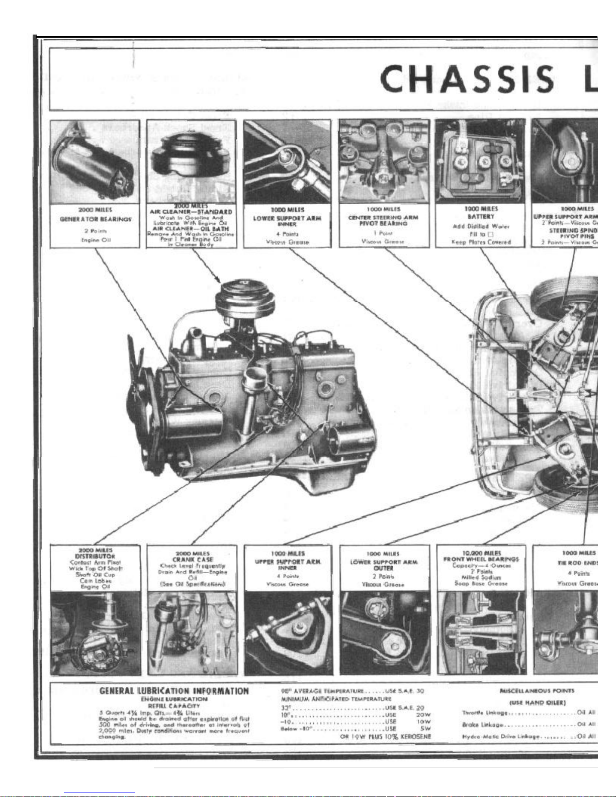
1 LUBRICATION
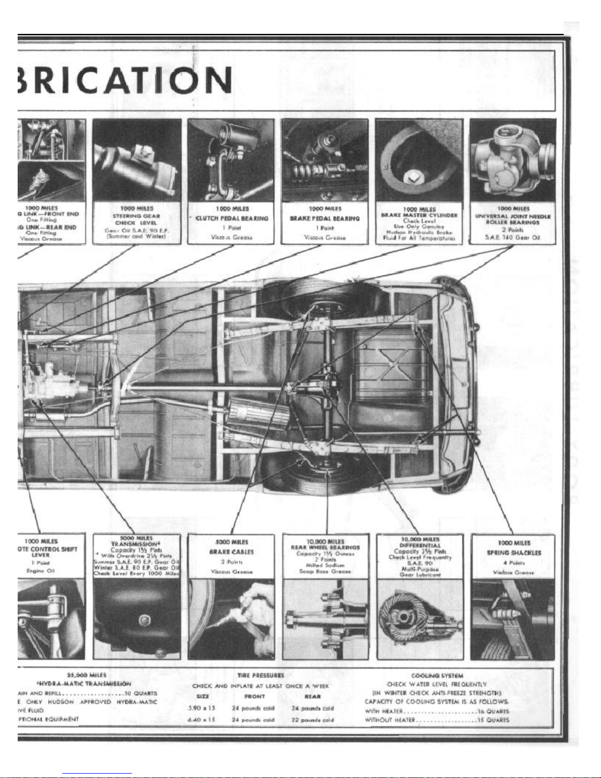
LUBRICATION 2
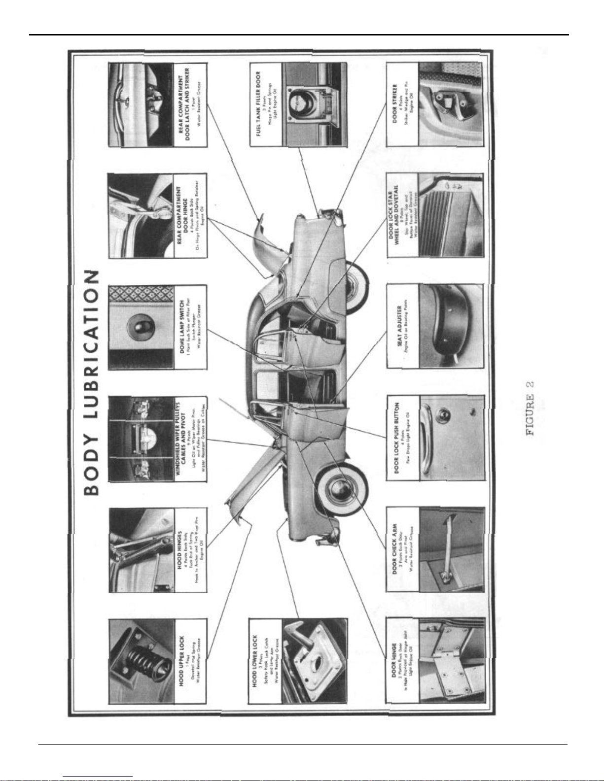
3 LUBRICATION

LUBRICATION 4
SECTION
LUBRICATION
Proper lubrication is the life of every piece of
mechanism. This is particularly true of the motor car.
Correct lubrication spells the difference between long
life or rapid and premature wear.
For this reason, a definite plan and schedule for
application is necessary in order to provide the various
bearing surfaces with the right amount of the correct
lubricant at the proper intervals.
It is a well-known fact that one type of lubricant
will not suffice for all applications. The degree of load
carried and operating conditions make necessary the
use of different types of lubricants.
In order to familiarize Hudson mechanics on the
proper lubrications of the engine, chassis and body;
lubricating charts indicating points to be lubricated,
type of lubricant to be used and the frequency of
application are shown in this Manual.
NOTE: Quality lubricants are used in the course of
assembling every new car. These need not be
changed until the recommended mileage period
shown in the Lubricating Schedule.
1
the oil filter passageway and permits full pump flow
direct through the main oil gallery, extending the
full length of the crankcase. This oil gallery is
intersected by drilled leads to all main and camshaft
bearings and the valve tappets.
Through the drilled crankshaft, oil pressure from
the main bearings is distributed to each connecting
rod bearing. An angular hole drilled through the
large end of each connecting rod and upper half of
bearing shell deposits a uniform spray of oil on all
cylinder walls.
Fitted in the front end of main oil gallery is an oil
trough that conducts a small stream of oil to the
timing chain and sprockets.
The oil measuring gauge seats on a tube pressed
in the crankcase at the left rear side. A pressure type
oil signal switch mounted above the oil pump and
connected with the main oil gallery operates the
dash oil signal light which shows red when the oil
pressure drops below approximately 13 pounds
ENGINE OIL
ENGINE OILING CIRCUIT
Pressure lubrication to all engine bearings is maintained by a rotor type oil pump m o u n t e d on the right
side of crankcase and driven by a worm gear on the
camshaft. Oil is drawn by the suction side of the pump
through a pipe connecting with a floating screen fixed
in the oil pan.
The oil pump parts consist of an inner and outer
rotor, a shaft and the body and cover. No adjustment
of the pump is required. Oil pressure is regulated by a
built-in, nonadjustable release valve and spring. These
are accessible for inspection or cleaning through a plug
opening at the left rear side of engine.
When the engine is started, the release valve has
moved to a position that closes the oil passage-way to
Select oils from the well-known brands and of
the proper viscosity to suit your seasonal and driving requirements.
The oil refiners or marketers supplying oils are
responsible for the quality of their product and their
reputation is the car owner's assurance of receiving
high-grade lubricants.
It is most important that the oil should have the
ability to flow at low temperatures to permit easy
starting and at the same time, afford adequate lubrication when the engine is a t normal operating temperatures. The oil selected should be based on its ability to
perform these two functions at the lowest anticipated
temperatures expected before the next oil change period. The following table will be helpful in making this
selection.
5 LUBRICATION
FOR USE
90° Average Temperature S.A.E. 30
32° Minimum Temperature S.A.E. 20
10° Minimum Temperature 20W
-10º Minimum Temperature 10W
Below -10° Temperature, 5W. or 10W plus
10% Kerosene
Your Authorized Hudson Dealer, who has had
long experience with the brands of oil available
in your locality, will be glad to help you with
your lubrication problems.
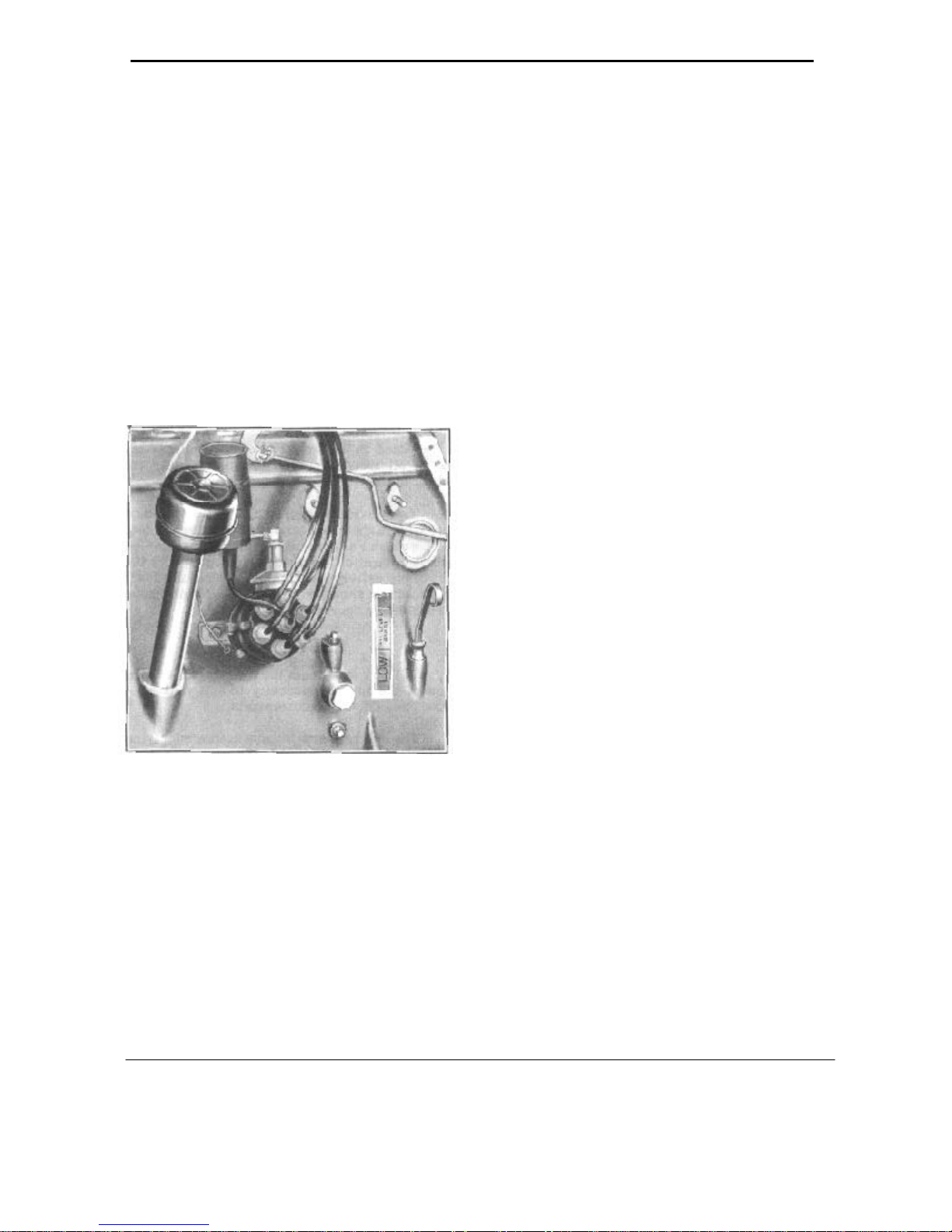
ENGINE OIL LEVEL - The level should be
checked each time you purchase gasoline. The
oil level gauge is located on the left side of the
engine.
WHEN TO CHANGE ENGINE OIL
The oil which is placed in the engine at the
factory should b e drained and replaced after the
first 500 miles of operation.
Thereafter, at intervals of 2,000 miles the
reservoir should be drained and refilled with
new oil of good quality. If the car is operated
constantly in dusty areas or for short distances at
low speeds during cold weather, which permits
foreign matter and sludge to accumulate, it
should be changed more frequently. However,
the actual change period is largely dependent on
the individual driving circumstances.
NOTE: Darkening or discoloration of oil does
not always mean that it is unsatisfactory. But
evidence of dilution or dirt is good indication
that the oil should be changed and the filter
cartridge should be replaced.
CAUTION: The use of flushing oils or compounds is not recommended. However, in the
event they are used, the oil reservoir should
be thoroughly drained before installing new
oil.
FIGURE 3
For normal operation, the oil level is satisfactory when it is within the "Oil Level Range."
For high speed operation, the level should be
maintained near the full mark. (Top line on the
"Oil Level Range.") Figure 3.
To make an accurate check, it is best to wait a
minute or two after shutting off the engine to
permit the oil to drain back into the reservoir
(oil pan). Oil is added through the oil filler
opening by removing the filler cap.
ENGINE OIL CAPACITIES - The total engine
oil capacity is 5-1/2 quarts. When the oil is drained
in the conventional manner, the refilling quantity is
5 quarts.
Approximately two quarts of oil are required
to bring the level from the "Low" to "Full" mark.
BREAK-IN OIL - Should the use of so called
"break- in" oils or special compounds for breaking in new engines be decided upon, make sure
the supplier guarantees that they contain no
harmful ingredients.
LUBRICATION SCHEDULE
The lubricants placed in your car at the time
of assembly are of the best quality and need
not be changed until the recommended change
period shown in the Lubrication Schedule has
been reached.

LUBRICATION 6
AT 500 MILES
Drain engine oil reservoir and refill with new oil of good quality. See "Engine Oil" - Page 4.
EVERY 1,000 MILES
VISCOUS CHASSIS LUBRICANT
Points Points
Drag Link
Upper Support Arm Outer
Upper Support Arm Inner
Lower Support Arm Outer
Lower Support Arm Inner
Brake Pedal Bearing
Engine
Door Lock Push Button
Door Hinge
Door Striker Wedge
Fuel Tank Filler Door Hinge and
Spring
Windshield Wiper Cables at Pulleys
Door Lock Star Wheel and Dovetail
..
Rear Compartment Door Latch and
Striker
Door Check Arm
Check Oil Level
WATER RESISTANT LUBRICANT
2
2
4
2
4
1
ENGINE OIL
Points Points
4
8
4
3
Points Points
4
8
1
4
Center Steering Arm Pivot Bearing.
Tie Rod End
Steering Spindle Pivot Pins
Clutch Pedal Bearing
Rear Spring Shackle Bushing
Hood Hinge
Windshield Wiper Pulley
Remote Control Shift Lever
Rear Compartment Door Hinge
Dome Light Switch
Door Striker
Hood Upper Lock
Hood Lower Lock
1
4
2
1
4
8
4
1
8
2
4
1
2
E. P. GEAR LUBRICANT - S.A.E. 80 WINTER, S.A.E. 90 SUMMER
Transmission
Overdrive
Hydra-Matic Drive Transmission Check Level
MULTI-PURPOSE GEAR LUBRICANT - S.A.E. 140
Rear Axle Check Level
Universal Joint Needle Rollers 2 Points
Check Battery Electrolyte Level and Gravity.
Check Coolant Level and Anti-Freeze Strength.
Check Level
Steering Gear Check Level
Check Level
HYDRA-MATIC DRIVE FLUID
GEAR OIL - S.A.E. 140
DISTILLED WATER
WATER OR ANTI-FREEZE

7 LUBRICATION
HUDSON HYDRAULIC BRAKE FLUID
Check Brake Master Cylinder Fluid Level
.
EVERY 2,000 MILES
Perform operations included in 1,000 mile lubrication, in addition to the following:
ENGINE OIL
Engine - Drain Oil Reservoir and Refill.
See "Engine Oil," Page 4.
Generator 2 Points
Distributor 4 Points
Air Cleaner - Standard - Wash and Re-oil
Air Cleaner - Oil Bath - Remove, wash and add
new oil.
Oil Filler Pipe Cap - Wash and Re-oil.
Throttle Operating Linkage All Joints
Brake Operating Linkage All Joints
EVERY 5,000 MILES
Perform operations included in 1,000 and 2,000mile lubrications, in addition to the following:
Oil Filter Renew cartridge
E. P. LUBRICANT - S.A.E. 80 WINTER, S. A. E. 90 SUMMER
Transmission Drain and Refill Overdrive Drain and Refill
VISCOUS CHASSIS LUBRICANT
Brake Cables Clean and Lubricate
EVERY 10,000 MILES
Perform operations included in 1,000 mile, 2,000 mile and 5,000 mile lubrications, in addition to the
following:
VISCOUS CHASSIS LUBRICANT
If springs are equipped with metal covers use Viscous Chassis Lubricant using special lubricating
clamp. If springs do not have metal covers, do not lubricate.
MULTI-PURPOSE GEAR LUBRICANT - S.A.E. 90
Rear Axle Drain and Refill
IMPORTANT: When checking the level of the lubricant in the rear axle and transmission, make
sure that the lubricant has stopped foaming. If the car has been run for a considerable length of
time, it should be permitted to stand long enough to allow the oil to reach the true level before
checking.
Hydra-Matic Oil Level Indicator Clean
SODIUM SOAP BASE LUBRICANT
Front Wheel Bearings Remove, Clean and Repack
Rear Wheel Bearings Remove, Clean and Repack
VERY 25,000 MILES
HYDRA-MATIC DRIVE FLUID
Hydra-Matic Drive Transmission Drain and Refill

ENGINE TUNE-UP 8
SECTION 2
ENGINE TUNE-UP
SPECIFICATIONS
Cylinder Compression
Vacuum, Intake Manifold
Valve Tappet Clearance (Hot)
Battery Specific Gravity
Starting Motor
Cranking Voltage
Cranking Amperage
Stall Test:
Volts
Amperes
Torque
Coil Amperage Draw:
Engine Stopped
Engine Idling
Distributor:
Point Gap
Cam Angle - (Dwell)
Spring Tension
Condenser Capacity
Advance: Automatic
0° at 300 R.P.M.
1° at 350 R.P.M.
4.5° at 500 R.P.M.
12° at 1325 R.P.M.
13.5° at 1500 R.P.M.
Minimum 100 lbs.
17-20" Hq.
Intake .010" - Exhaust .012"
1.270
5 0 Volts
Approximately 160 Amps
2 0 Volts
Maximum Amps 280
Min. Ft. Lbs. 4.4
5.0 Amps
1 5 - 2.0 Amps
.020"
39º
17 to 20 oz.
21-25 Mfd.
Vacuum
0° at 5-1/4"
1° at 5-3/4"
4° at 7-1/2"
6° at 8-3/4"
7.5° at 9-1/2"
Generator Output:
Cold - at 870 to 970 R.P.M
Cold - at 1925 to 2125 R.P.M.
Hot - at 950 to 1050 R.P.M
Hot - at 2350 to 2550 R.P.M.
Voltage Regulator:
Contact Point Gap
Contact Close
Contact Open (After 15 Amp Charge)
Voltage Regulator Operates
Spark Plug Gap
Fuel Pump (Carter)
Pressure
Volume
Carburetor
Float Setting
Pump Travel
Idle Adjustment
Climatic Control
6 4 Volts 0 Amps
8.0 Volts 45.0 Amps
6.4 Volts 0 Amps
8.0 Volts 45.0 Amps
Minimum .015"
6.3 to 6.8 Volts
4.1 to 4.8 Volts
7.25 Volts 22 Amps at 100° F.
.032"
4 lbs. min. - 5 lbs. max. @ 1800 R.P.M.
1 quart 60 seconds 500 R.P.M.
Carter - Model WAI-2009S
1/2"
16/64"
1/2 to 1-1/2 turns open
Set one point lean
9 ENGINE TUNE-UP
ENGINE TUNE-UP
Engine tune-up is important in maintaining
engine performance, fuel economy, dependability, and complete owner satisfaction. Modern high
speed engines demand accurate diagnosis and
adjustments. It is recommended that the engine be
tuned every 5,000 miles.
The tune-up procedure that follows is arranged in the usual order of performance, which
is generally: compression, ignition, carburetion.
Various manufacturers of testing equipment have
set up specific procedures for their units which
may be followed.
Many of the tests involved in the tune-up are
dependent upon a battery in good condition. If the
battery is below standard it should be recharged,
or replaced with a fully charged battery before the
tune-up.
ENGINE
COMPRESSION
An engine that fails to develop proper compression cannot be tuned. Compression should be
checked with the engine at operating temperature
with a reliable compression gauge. Test is made
with ignition switch off and all plugs removed.
valve. If two adjacent cylinders show low compression readings, check for a leaking cylinder
head gasket or loose cylinder head.
To differentiate between ring and valve leak,
place a small quantity of oil on top of each piston
and re-test. Oil will temporarily seal a ring leak
and result in near normal compression. Little or no
improvement will be noted if valve is leaking.
Correct any unsatisfactory condition found
during the compression test before continuing with
the tune-up.
SPARK PLUGS
Upon satisfactory completion of the compression
test, inspect, clean and adjust spark plugs.
1. Spark plugs with burned, blistered or cracked
porcelains, o r with pitted o r burned electrodes,
should be replaced with new plugs of the same
type. For cast iron and aluminum cylinder
heads, use Champion H-8 spark plugs. See
"Electrical Section".
2. Adjust spark plug gaps to .032" using a bending
tool and wire loop gauge.
1. Loosen spark plugs to break free any accumulated
carbon.
2. Use an air hose and blow out all dirt and carbon
from spark plug cavities before removing
plugs.
3. Remove all plugs.
4. Insert compression gauge in each spark plug
hole in turn and crack engine with starter at least
4 compression strokes.
NOTE : Check reading on first and final stroke.
5. Compression at each cylinder should be at least
100 pounds and should not vary more than 10
pounds.
NOTE: If compression gauge moves up in
jerky steps of 10 or 20 pounds at a time, it
generally indicates a sticking or leaking
valve.
3. Install new gaskets on the plugs and replace
plugs in cylinder head. Tighten to 25 to 30
pounds with a torque wrench.
4. Examine spark plug wires for loose terminals,
cracked or broken insulation. Replace defective
wires.
ENGINE TUNE-UP 10
VACUUM TEST
An engine in good :condition - will show a
steady, or slight fluctuating , high vacuum
reading from 18" to 21". Vacuum readings
are affected by altitude. Over 2000 feet the
vacuum gauge will show about one inch lower
for each 1000 feet of elevation.
1. Remove wiper hose at intake manifold and
connect vacuum gauge hose. (If the engine
has a combination fuel and vacuum
pump,disconnect the booster pump line at intake
manifold.)
2. Check carburetor and intake manifold nuts
for tightness.
3. Connect one lead of tachometer to the distributor
primary terminal and the other lead to engine for
ground. Adjust carburetor to obtain a smooth idle
at 540 to 580 R.P.M. If car is equipped with
Hydra-Matic Transmission, set idle speed at 490-
510. Vacuum readings at sea level may be interpreted generally as follows:
TAPPET ADJUSTMENT
1. Raise front of car, place stand jack under
frame cross member and remove right front
wheel.
2. Remove bolts on the fender side dust shield
and attaching parts and take out shield from
under the fender.
3. Remove front and rear tappet covers and
breather pipe . Take out the rear tappet cover
by sliding cover forward and out.
4. Adjust tappets and re-install parts.
CYLINDER BALANCE TEST
The Cylinder Balance Tester compares the eveness of the power output of each cylinder in the
engine.
1. Connect the vacuum gauge in Figure 2 and
set the throttle until engine is running at
1500 R.P.M.
18 - 21" Steady or with slight fluctuation: En gine in good condition.
15" Steady: Incorrect ignition timing.
10" Steady: Incorrect valve timing, or
burned valves.
15 - 21" Fluctuating: Sticking valves or com pression leak.
12 - 16" Drifting: Carburetor too rich or too
lean
.
Any number of engine conditions may
cause the same action of the vacuum gauge.
The exact cause must be established by process
of elimination.
VALVE TAPPETS
Check the valve tappets clearance when
the engine is at normal operating temperature.
Correct valve clearances are .010" for
intake valves, .012" for exhaust valves.
FIGURE 2
2. Ground the master clip of the cylinder balance
tester and connect individual leads to the spark
plugs 2-3-4 and 5. Engine will now run on 1 and 6.
3. Note the reading on the vacuum gauge. Make
the same test on each pair of cylinders in the
following sequence. 6 Cylinders 1-6, 2-5, 3-4.
11 ENGINE TUNE-UP
NOTE: A variation of more than 1 inch of
vacuum or 40 R.P.M. between pairs of cylinders being tested indicates either a defective
plug or unequal compression in a cylinder.
To isolate one weak cylinder, short out half the
cylinders. The half giving the lower reading will
include the weak cylinder.
Air bubbles prevalent in the radiator filler neck
(radiator filled with coolant to th e overflow pipe)
indicates a leaking cylinder head gasket, cylinder
head or internal cracks in the water jackets.
An extreme blow-by at the oil filler pipe indicates defective piston rings. (Compression pressure by-passing the piston rings.)
BATTERY SPECIFIC GRAVITY
Check the battery specific gravity with a hydrometer. A battery when fully charged should
read 1.270 specific gravity at 70° F. A uniform
hydrometer reading below 1.225 at 70° F. indicates a low battery that should be recharged.
it will crank the engine for 1/2 minute and the
voltage does not drop below 4-1/2 volts. Slow
cranking speed or lower voltage may be due to
high resistance in the starter circuit. Check cables
and retest. (DO NOT crank for more than 1/2
minute at a time.)
A standard cell tester may be used to make the
load test. The cell tester has a shunt across the
terminals which places each cell under load. Each
cell should show 1-1/2 volts or over, and the variation between cells should not exceed .15 volts.
If a Starter-Battery Tester is not available, a
voltmeter can be connected across the battery terminals while cranking t he engine with the starting
motor. The battery is in good condition if the
starter cranks the engine at a good speed for 1/2
minute and the voltage does not fall below 4-1/2
volts. DO NOT crank for more than 30 seconds
without allowing starter motor to cool.
NOTE: A slow cranking speed or voltage lower
than 4-1/2 volts indicates a weak cell or high
resistance in the connections to the starter.
Check battery cables and connections and repeat the "Load Test".
FIGURE 3
BATTERY LOAD TEST
Battery may be tested under load by connecting a voltmeter across the terminals and cranking
the engine. Battery is satisfactory if
DISTRIBUTOR
1. Remove wires from cap anu inspect cap and
rotor for cracks and burned or corroded contacts.
Replace defective parts.
2. Clean spark plug cable sockets with tool No.
KMO-230.
CONTACT POINTS
1. Inspect distributor contact points f o r alignment,
corrosion, burning o r pitting and clean with
carbon tetracholoride.
2. Replace burned or corroded points. If points are
badly pitted, check condenser for over or under
capacity.
3. With a feeler gauge set the points for the proper
gap. Correct gap is .020".
NOTE: Contact points adjustment is made by
loosening the clamp screw (B) Figure 4, holding
ENGINE TUNE-UP 12
the stationary contact plate, then turning
eccentric adjusting screw (D) to move the
contact point. Tighten clamp screw when
correct gap is secured.
FIGURE 4
4. Bend stationary contact point if necessary
to secure correct alignment.
BREAKER ARM SPRING TENSION
1. Hook a spring scale to the breaker arm at the
contact and pull at right angles to the contact
surfaces. Tension should be 17 to 20 ounces
just as the points open.
2. Adjust spring tension by loosening screw
attaching breaker arm spring to plate and
move end of spring in or out of clip as
necessary.
CONDENSER
1. Inspect condenser lead to see that it is not
frayed or broken and is connected securely to
breaker arm clip. Condenser mounting screw
must make tight ground to breaker plate.
Ground wire from breaker plate to subplate
must be securely connected.
DISTRIBUTOR DWELL TEST
Check distributor cam angle or dwell on a distributor tester to determine the cam angle or degrees of
dwell of the distributor point. This should be 39 degrees with distributor contact point set at .020".
If the dwell angle is too great, the contact point gap
is set too close. If the dwell angle is too small, the
contact gap is too wide. An erratic reading of the
Dwell Meter will indicate faulty contact, a faulty
breaker plate, a worn distributor shaft and bearings. A
change of dwell angle when accelerating or deaccelerating, the engine will indicate a faulty breaker plate,
bearing or support plate.
VACUUM ADVANCE ADJUSTMENT
Vacuum should be checked on a distributor tester
that has a controlled source of vacuum and a vacuum
gauge
.
If the vacuum advance range does n ot conform
with specifications, it may be varied by inserting or
removing washers under the sp r in g in the vacuum
chamber. Carefully check for leaky diaphragm and
sticking linkage.
AUTOMATIC ADVANCE
Place distributor on tester and check the advance
curve R.P.M.'s against the degree of advance.
If the degree of advance is more than specifications
call for at the same R.P.M., it indicates that the governor spring tension is too weak and the advance is too
rapid.
If the degree of advance is less than specifications,
call for at the same R.P.M., the spring tension is too
stiff and the advance is too slow.
In most cases, the tension of the spring may be
increased or decreased by bending the brackets on the
weight plates to which the springs are attached, in
order to make the springs conform to specifications.
Check the advance both up and down the speed
range so that the sluggish action of the governor will
be indicated and may be corrected by cleaning and
lubrication.
Check condenser with suitable equipment and
if capacity is not within range of .20 to .25 MFD,
replace with new part.
NOTE: Every 2,000 miles, lubricate contact arm
pivot, wick top of shaft, cam lobes and 3 to 5 drops
of medium engine oil at oiler.
13 ENGINE TUNE-UP
COIL
If a faulty coil is ,suspected, the coil should be
tested with a test light or approved coil testing
equipment.
A quick test with the coil on the car can b e
made by removing the high-tension wire from the
center of distributor cap and hold end of wire 1/4"
from cylinder head and while cranking engine, if
a spark occurs regularly the coil can be considered satisfactory.
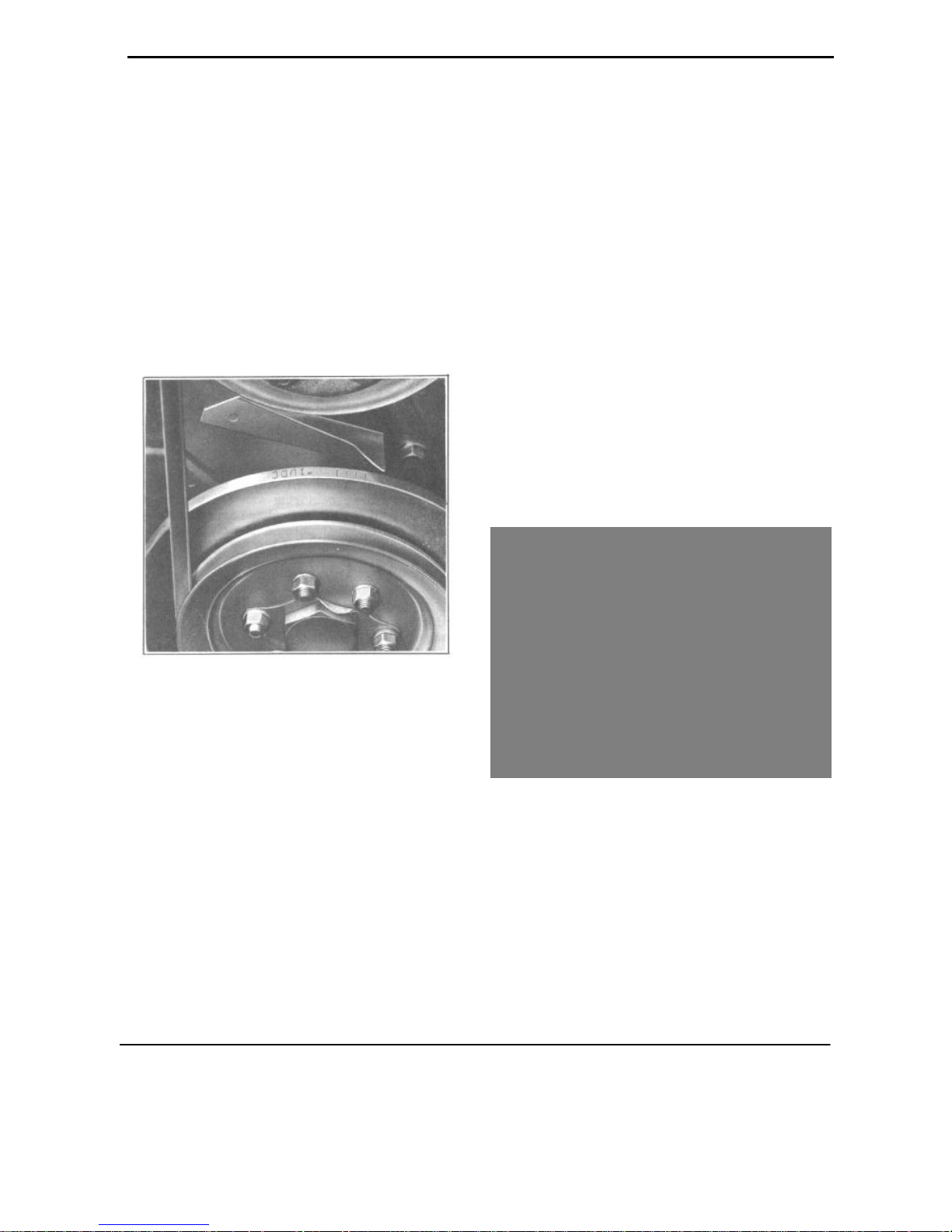
IGNITION TIMING
1. Place a chalk mark on the long line before No.
1-U.D.C. on the vibration dampener, Figure 5.
1 piston starts up on compression stroke. Continue
cranking until long line on dampener lines up with
pointer. Loosen distributor quadrant screw and
rotate distributor clockwise to the limit of the slot
in the quadrant. Remove secondary wire from
center of distributor cap and hold bare end of wire
about 1/8" from the cylinder head. With ignition
switch on, slowly rotate the distributor counterclockwise just until a spark jumps from the wire to
the cylinder head; then tighten quadrant screw.
Spark setting may be advanced with fuels of
high octane rating.
Correct ignition timing is indicated by a slight
"ping" at about 15 M.P.H. when accelerating at full
throttle from 10 M.P.H. in high gear. If no "ping"
is heard, timing should be advanced one quadrant
graduation mark at a time until the "ping" is heard.
CRANKING VOLTAGE
1. Connect the negative voltmeter lead to the
starter switch terminal (where the battery to
starter cable is connected), Figure 6.
FIGURE 5
2. Connect one lead of the power timing light to
No. 1 spark plug and the other lead to the
negative terminal of the battery.
3. With the engine idling properly, the timing
light flash should occur when the chalk mark
is in line with the pointer on the timing chain
cover.
If timing is off, make the necessary correction
by loosening the distributor advance arm screw
(on octane selector) and rotate distributor clockwise for retard and counterclockwise for advance.
4. Increase engine speed. The vacuum advance
should be at full retard position but should
advance readily when the engine speed is in
creased.
To set the timing without a timing light, remove No. 1 spark plug and crank engine until No.
FIGURE 6
2. Connect the positive voltmeter lead to engine
for a ground.
3. With the ignition key off, engage the starter
motor and note the reading on the voltmeter.
The cranking voltage should read 5 volts or
more.
CAUTION: Crank engine intermittently (not
more than 30 seconds) to prevent starter motor
from overheating.
volts, check the battery and engine ground cables,
starter cable and the starter solenoid to determine
the low reading.
BATTERY AND ENGINE GROUND STRAPS
1. Connect the voltmeter positive lead to the
battery ground terminal, Figure 7.
FIGURE 7
2. Connect the voltmeter negative lead to engine
ground and a jumper to the frame.
3. With ignition off, crank engine and make volt
meter reading, (should not be more than .2).
4. If more than .2, check ground strap connections
from battery to engine. Replace defective ground
straps.
ENGINE TUNE-UP 14
FIGURE 8
AMPERAGE DRAW TEST
1. Turn battery starter test know to "off" position
and the voltmeter "selector switch" to the 15
volt position and connect test leads, Figure 9.
STARTER CABLE
1. Connect the positive voltmeter lead to the
"BAT" terminal of the starter and the negative
lead to negative battery post.
2. Crank engine again (ignition off). If the
voltmeter reading is more than .2, check
for loose connections or frayed cables.
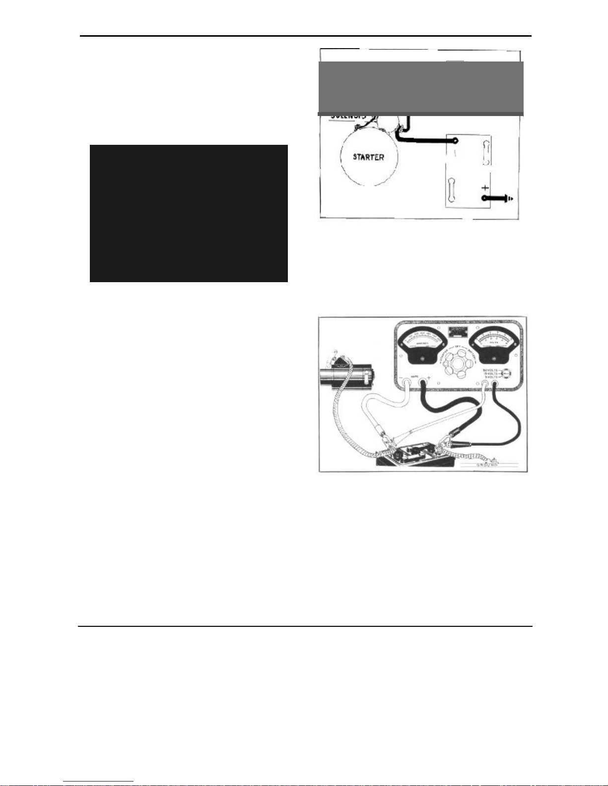
STARTER SOLENOID
1. Connect negative voltmeter lead to "BAT" terminal of starter solenoid switch and positive lead to
motor terminal of the solenoid switch, Figure 8.
2. Close the solenoid electrically to crank the
engine; and if the reading is more than .2
volts, replace solenoid switch.
FIGURE 9
2. Press starter switch and crank engine for
approximately 15 seconds and note the
"exact" reading on voltmeter.
3. Release Starter Switch and turn Starter-Battery
Tester knob clockwise until the voltmeter
reads "exactly" the same as when cranking the
engine. Ammeter reading should be 140 to
160 amperes (engine warm).
15 ENGINE TUNE-UP
4. Turn tester to off position after completing test.
NOTE: Excessively high readings indicate a short
in the starting motor circuit or an excessive drag
on the motor due to a bent armature shaft or the
field coils touching the armature. Low readings
indicates excessive resistance in the circuit caused
by loose connections, worn brushes, or weak brush
spring tension.
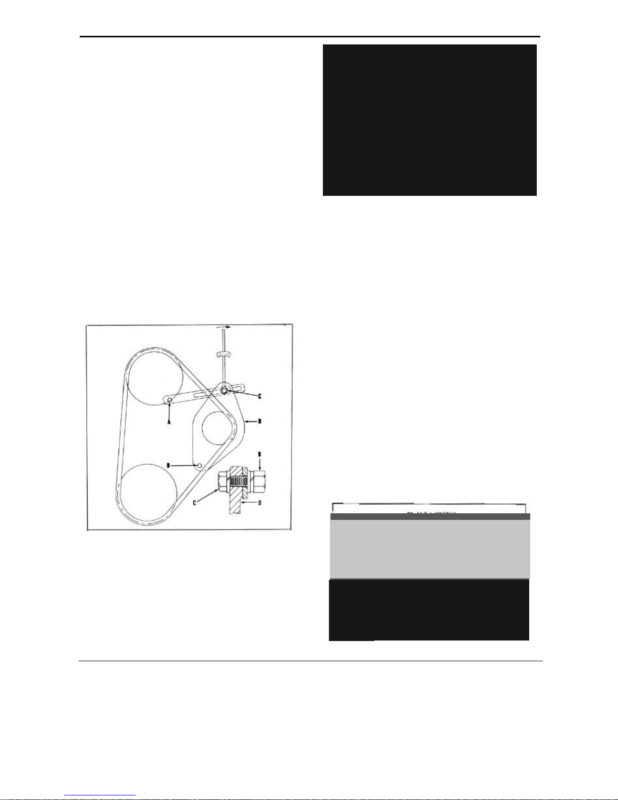
FAN BELT ADJUSTMENT
1. Loosen generator adjusting bracket bolt (A Figure 10), Nut (B) and 2 generator support
bracket bolts (D), three to four turns.
2. Apply a torque wrench approximately 12"
long and as nearly vertical as possible to head
of generator adjusting bracket bolt (C) and
pull generator against fan belt.
3. With torque wrench indicating 10-1/2 foot
pounds tighten generator adjusting nut (B)
securely. Remove torque wrench and tighten remaining 3 bolts securely.
FIGURE 11
2. Install a jumper from generator field terminal to
a ground. Momentarily raise the engine to about
1250 R.P.M. the reading on the ammeter should
read 45 amperes minimum output.
CAUTION: The engine MUST NOT be run for
more than a few seconds while making the
above test, due to danger of burning out the
generator. All lights and accessories must be
turned off also to prevent damage due to excessive voltage.
FIGURE 10
GENERATOR
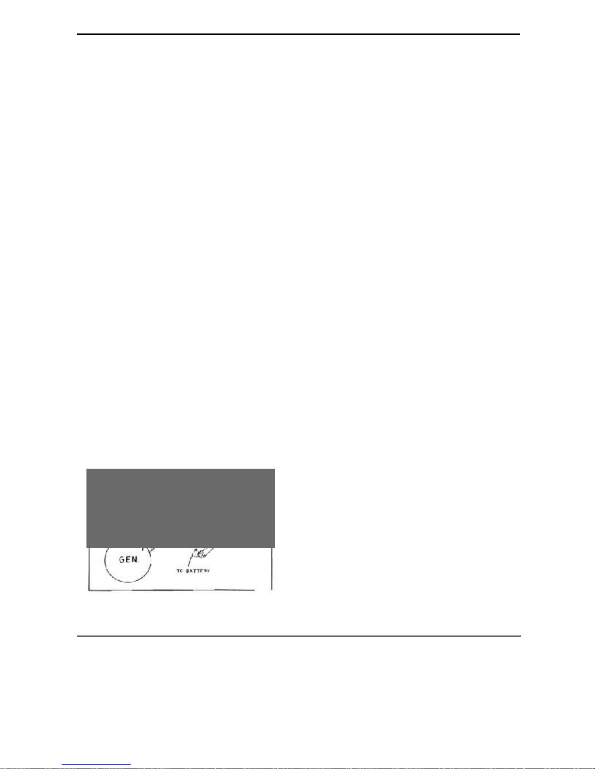
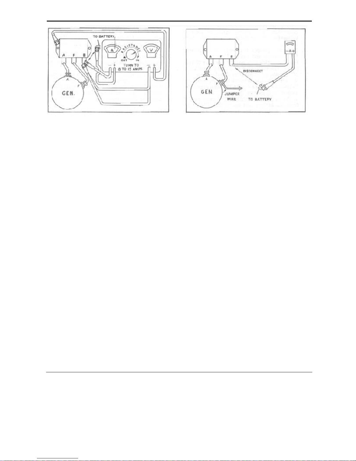
GENERATOR OUTPUT CHECK
1. Disconnect battery lead at voltage regulator
"B" terminal; connect the ammeter negative
lead to the regulator "B" terminal and the
positive lead to the wire disconnected from
the regulator, Figure 11.
NOTE: A 11 generator tests should be made
with the generator circuit at normal operating
temperature.
GENERATOR CIRCUIT RESISTANCE CHECK
1. Disconnect battery lead at voltage regulator "B"
terminal; connect the ammeter negative lead to
the regulator "B" terminal and the positive lead
to the wire disconnected from the regulator,
Figure 12.
FIGURE 12
ENGINE TUNE-UP 16
2. Install the negative voltmeter lead to the generator "A" terminal an d the positive voltmeter
lead to the battery negative terminal.
3. Connect a jumper between t he generator "F"
terminal and a ground.
4. Run the engine at a speed to deliver 20amperes.
The voltmeter should not read more or less than
8 (tenths) of a volt.
5. If the resistance is more than .8, make the
following checks with the ammeter connected
as in paragraph 1.
a. Remove the positive voltmeter lead from the
battery and install to the "A" terminal at the
voltage regulator. Ammeter should show less
than .1 (tenth).
b. Connect the voltmeter negative lead to the
regulator "A" terminal and the volt- m e t e r
positive lead to the regulator "B" terminal.
Ammeter should not show more than .3
(tenths).
c. Next, connect the voltmeter positive lead to
the battery negative terminal, negative lead to
"B" terminal on regulator. Ammeter should not
show more than .5 (tenths).
d. Connect the voltmeter positive leads to en g
in e ground, negative wire to base of regulator.
Ammeter should show .2 (tenths) or less.
CIRCUIT BREAKER CHECK
1. Disconnect the battery wire at the voltage regulator "B" terminal and connect the ammeter
between the voltage regulator " B" terminal and
the wire disconnected, Figure 13.
2. Connect voltmeter positive lead to base of
regulator and negative voltmeter to the generator "A" terminal.
3. Set carburetor adjusting screw so engine will
idle at approximately 400 R.P.M.
4. Increase engine R.P.M. by carefully rot a t in g
the accelerator bellcrank while watching the
voltmeter.
NOTE: When the voltmeter reads at any point
between 6.3 to 6.8 volts the circuit breaker
points should close and the ammeter will show
the generator is charging. When the circuit
breaker points close, a slight drop back of the
voltmeter needle will be noticed. In the eve nt
the drop back is not evident, slightly discharge
the battery and recheck.
5. Next, slowly reduce engine speed and watch the
ammeter.
NOTE: When the ammeter reads 4 to 6 amperes, negative side of zero, the circuit breaker
should open and the ammeter needle will return
to zero. Perform operation 4 and 5 several times
until you are sure your readings are correct.
To determine whether the circuit breaker
points are closing at the proper generator voltage
and also whether they will open upon deceleration by amperage from the battery proceed as
follows:
FIGURE 13
6. Proper adjustments can be made by bending the
spring hanger on the circuit breaker. Increasing
the tension raises the opening voltage; decreasing the tension lowers the opening voltage.
Contact gap must not be less than .015".
VOLTAGE REGULATOR CHECK
1. Disconnect the battery wire at the voltage regu-
lator "B" terminal and connect the test ammeter
between the voltage regulator "B" terminal and
the wire disconnected, Figure 14.
2. Connect the voltmeter positive lead to the regu-
lator base and the negative lead to the regulator
"B" terminal.
3. Run engine at approximately 2,000 R.P.M.
4. Vary resistance until ammeter reads 19 amperes
and then check the voltmeter reading which
should be 7.25 volts. (Hot, cover in place.)
17 ENGINE TUNE-UP
FIGURE 14
NOTE: If the car is out of warranty the voltage
regulator can be set by bending the spring
hanger to get this necessary reading. The unit
must be final-checked with the voltage regulator cover in place as generally it will change
the reading from .1 to .2 of a volt and must be
compensated for in making this adjustment.
5. Stop engine, disconnect battery negative terminal and then proceed to remove the tester leaks
from the voltage regulator and install the wires
back on the "B" terminal of the regulator.
6. Install voltage regulator cover.
VOLTAGE REGULATOR ADJUSTMENT
1. Remove cover and change the armature spring
tension by bending the lower spring hanger.
Increasing the tension raises the operating voltage; decreasing the tension lowers it.
2. Replace cover and recheck.
FIGURE 15
2. Connect a Starter-Battery Tester directly across
the battery and set load to 45 amperes or use the
equivalent in sealed beam lamps.
3. Run engine to approximately 2000 R.P.M. amperage reading should be 36 amperes. If it is not
within a tolerance of one or two amperes of this
reading, the unit should be taken to an authorized Auto-Lite dealer for replacement.
NOTE: If car is out of warranty, remove the
voltage cover and adjust the current regulator
spring hanger to the necessary 36 ampere output. To prevent operation of the voltage regulator unit place a jumper across voltage regulator
points during this test. For final test always
replace the cover on the unit.
CAUTION: Momentarily touch t he negative
battery cable to the battery negative post to
determine that there is no spark between the
battery negative post and cable terminal then
connect negative cable.
3. After each adjustment, stop the engine and
restart. Bring up engine speed to deliver 15
amperes before taking a reading.
CURRENT REGULATOR CHECK
1. Disconnect the battery wire terminal "B"and
connect the test ammeter between the voltage
regulator "B" terminal and the wire disconnected,
Figure 15.
CURRENT REGULATOR ADJUSTMENT
1. Remove cover and change armature spring tension by bending the lower spring hanger. Increasing the tension raises the operating
amperage, decreasing the tension lowers it.
2. Replace cover and recheck. Stop and start engine
after each adjustment. Take readings with cover
in place.
ENGINE TUNE-UP 18
FUEL PUMP
FUEL PUMP TEST
To determine if the fuel pump is operating properly, make the following tests:
1. Be sure fuel lines are not blocked, leaking or
have a stricture that would retard the flow of fuel
to the pump. The flexible hose should be carefully
checked for deterioration or cracks.
2. Remove and clean sediment screen.
NOTE: If the combination fuel and vacuum
pump is used, in addition, remove and clean
the air filter screen located under the cover at
the top of the pump.
3. Make sure all connections are tight after replacement.
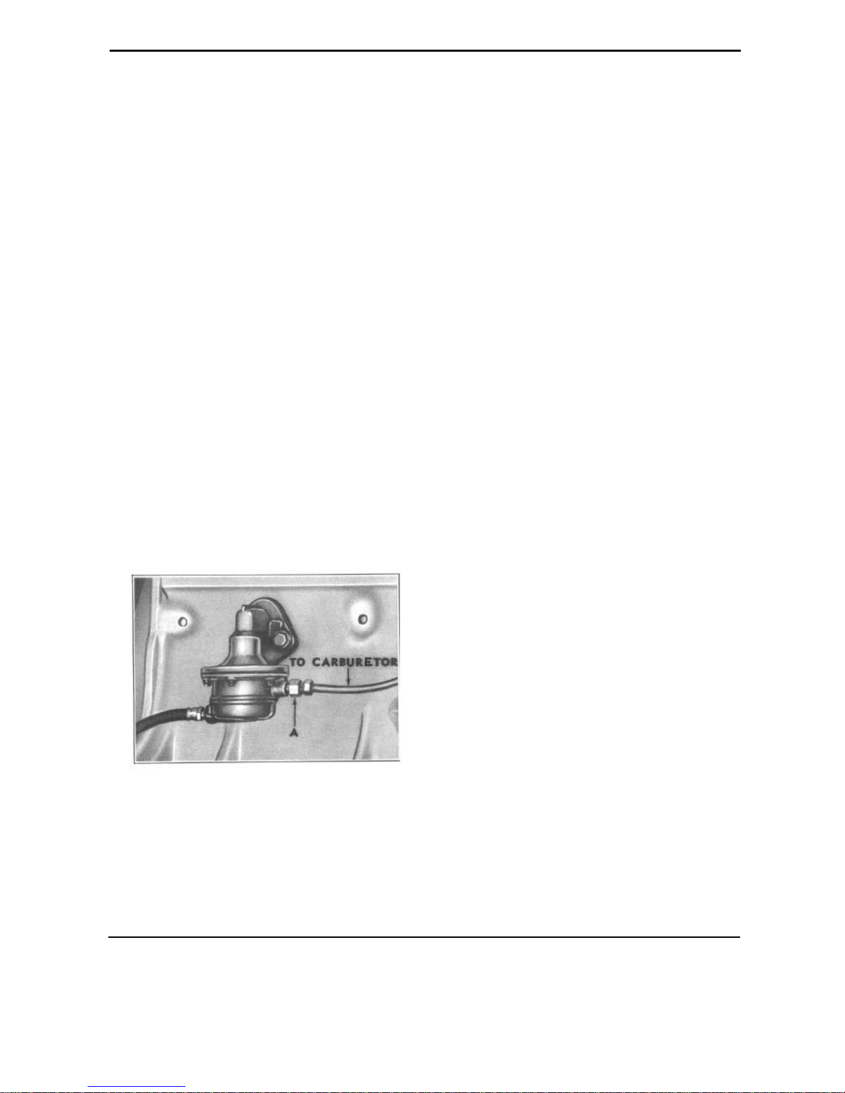
4. Disconnect the fuel line at the carburetor and
connect the fuel pump gauge, Figure 16.
5. Start engine and run at 1800 R.P.M. normal
pressure should be 4 lbs. minimum to 5 lb s .
maximum. Stop engine and watch pressure
gauge. Pressure should not fall perceptible after
engine is stopped.
VACUUM BOOSTER CHECK
To check the action of the vacuum portion of the
combination fuel and vacuum pump, connect a
vacuum gauge to the inlet port and disconnect
outlet. Gauge should show 8-1/2" of mercury at
120 R.P.M. and 12" at 1800 R.P.M.
MANIFOLD HEAT CONTROL
Check the manifold heat control valve to see
that spring is in good condition and valve is free.
If damper shaft is stuck, remove the thermostat and
spring, apply penetrating oil or kerosene and tap
shaft for end play to break carbon or corrosion.
The shaft should not be oiled. When properly
freed, check springs and thermostat before installing and replace them if weak.
CARBURETOR
CLIMATIC CONTROL
1. Remove t he carburetor Climatic Control Cover.
Check the heat control tube for leaks or obstruction and the choke valve and piston for free
movement. Choke valve should open of its own
weight when cover is removed.
2. Reinstall the cover with graduations down and
rotate counter clockwise to one point lean of
center graduation.
FIGURE 16
6. If pressure falls; leaking pump valves are indicated.
7. If pressure is below specifications, attach the
vacuum gauge to the inlet port of the pump and
operate the engine. Gauge should show a minimum of 6 inches of mercury for satisfactory
operation.
CARBURETOR INLET STRAINER
1. Remove bowl cover strainer nut, gasket, and
strainer screen. Clean screen and replace if corroded or damaged.
CARBURETOR FLOAT LEVEL
1. Remove air cleaner, carburetor dust cover and
screws attaching carburetor air horn.
2. Disconnect throttle connector r o d, bowl cover
and check float level with gauge J-818-1 Figure
17. Float level should be 1/2".
3. To adjust, make sure needle is seated, raise float
and press down on float lever lip with a screw
driver. Bend only a small amount at a time and
do not disturb the curvature of the lip.
19 ENGINE TUNE-UP
1. With throttle valve seated and connector link i n
lower hole (short stroke) pump travel should be
FIGURE 17
PUMP TRAVEL
16/64". Use Carter Pump stroke gauge T-109117-S if available.
2. Adjust pump travel by bending throttle connecting link at lower angle.
METERING ROD SETTING
NOTE: The correct setting of metering rod is
important and must be made after pump adjustment o r when leaner than standard rods
are installed.
FIGURE 18
1. Crack throttle valve .020" by placing gauge
J-1633 (Carter No. T-109-29) between throttle
valve and bore of carburetor on side opposite
the idle port, Figure 19.
1. With air cleaner and dust cover off remove
hairpin clip and disconnect spring from metering rod, remove metering rod and disc.
2. Insert metering rod gauge, J-1265 (Carter No.
T-109-102). Hold gauge vertical and be sure
gauge is seated in metering rod jet, Figure 18.
3. Press down on vacuum piston link directly over
piston until it contacts the pump arm. Clearance
between metering r o d pin and shoulder of
gauge should be less than .005" with throttle
valve seated. Gauge must not drag on pin.
4. Adjust by bending lip on piston link at (A). 5.
Re move gauge and install metering rod and
disc and connect metering rod spring.
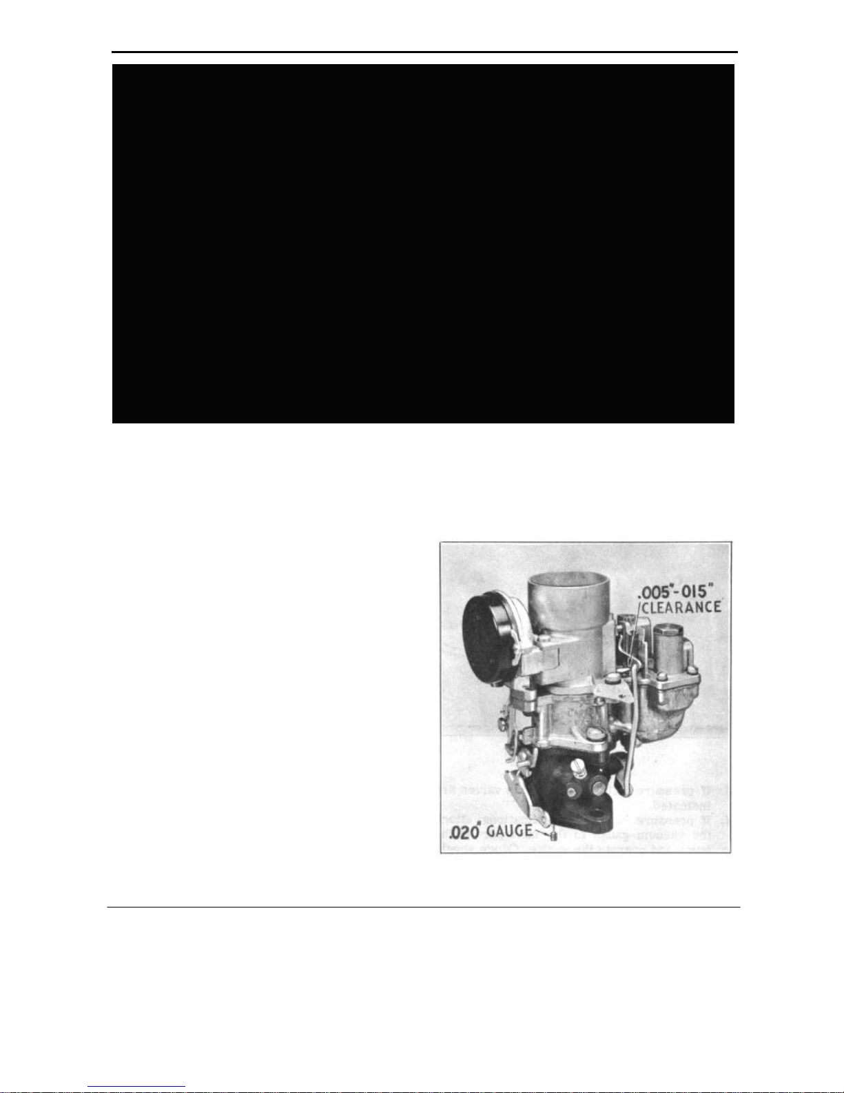
ANTI-PERCOLATOR ADJUSTMENT
NOTE: Carburetor must be removed from en-
gine.
FIGURE 19

2. Clearance between percolator rocker arm lip
and pump arm should be .005" to .015"
3. Adjust by bending the rocker arm, using Bending Tool J-1389 to make this adjustment.
FAST IDLE ADJUSTMENT
1. With fast idle cam in normal idle position,
tighten throttle lever adjusting screw (A), Figure 20, until it just seats against the cam.
ENGINE TUNE-UP 20
FIGURE 21
IDLE ADJUSTMENT
FIGURE 20
2. Hold throttle lever closed an d pull cam back
until low step is against but not on set screw
(B), Figure 20.
3. Clearance between lower edge of choke valve
and air horn should be 5/8" as shown at (A),
Figure 21.
4. Adjust by bending fast idle link at offset.
UNLOADER ADJUSTMENT
I. Open throttle wide and check clearance be-
tween lower edge of choke valve and air horn.
Clearance should be 7/16" (A), Figure 21.
1. Start engine and allow to warm up.
2. See that choke valve is wide open.
3. Set idle adjustment screw (A), Figure 22, 1/2 to
1-1/2 turns open to obtain smooth idle. Cars
equipped with Hydra-Matic; set idle at 490-510
R.P.M., 540 to 560 for standard transmission
and 575 for overdrive.
2. Adjust by bending cam (B) on throttle lever.
FIGURE 22

MAIN BEARING SIZE
21 ENGINE
SECTION 3
ENGINE
SPECIFICATIONS
ENGINE - GENERAL
Arrangement
No. Cylinders
Compression Pressure
Firing Order
Serial No. Location
Bore
Stroke
Piston Displacement .
Horsepower - Taxable
Horsepower - Actual.
Torque
CRANKSHAFT
Drive
Bearings
Type
No.
1.
2.
3.
4.
Radial Clearance
End Play
Timing Marks
Timing Chain
Timing Chain Width
Camshaft Sprocket
Crankshaft Sprocket
CRANKSHAFT
No.
1.
2.
3.
4.
1.
2.
3.
4.
Diameter
2.4988" to 2.4998" 1.530"
2.4988" to 2.4998" 1.500"
2.4988" to 2.4998" 1.500"
2.4988" to 2.4998" 1.750"
2.5006" to 2.5010"
2.5006" to 2.5010"
2.5006" to 2.5010"
2.5006" to 2.5010"
L Head
6
100 lbs. minimum
1-5-3-6-2-4
Right Hand Front
of Block
3"
4-3/4"
202 Cu. In.
21.6
104
158 ft. lbs. @ 1400
R.P.M.
Silent - Chain
4
Interchangeable -
Steel Back Babbitt
Diameter Length
2.375"
1.997"
1.965"
1.497"
.0005"
.003 to .005
On Sprockets and Chain
60 Links 3/8" Pitch
1"
42 Teeth
21 Teeth
x
x
x
x
x
Journal
Length
x 1.312"
x 1.250"
x 1.494"
x 1.500"
1"
11/16"
11/16"
1-1/8"
.0015"
Diametral Clearance
Adjusting Shims
Crankpins
End Play
Thrust
CONNECTING RODS
Material
Weight
Length - Center to Center
Bearing - Lower End
Type
Diameter & Length
End Play
Diametral Clearance.
Shims
Bushing - Upper End:
Material
Diameter & Length
Diametral Clearance
PISTON
Type
Material
Weight
Length (Overall)
Length - Pin Center to
Top
Piston Clearance
Ring Groove Depth
PISTON PIN
Type
Length
Diameter
Fit in Piston
Fit in Rod
PISTON RINGS
Material
Compression Rings
Width
Oil Rings
Width - Upper
Width - Lower
Gap Clearance
.0005" to .0015" None
1.937" to 1.938"x
1.125"
.003" to .009"
On No. 3 Bearing
Forged Steel
26 ozs.
8.183" to 8.193"
Precision Insert
Removable
Steel Back Babbitt
1.9375" x .962"
.007" to .013"
.0005" to .0015"
None
Steel Back Babbitt
.8465" x .870"
0" to .0003"
Cam Ground
Aluminum Alloy
10-1/4 oz.
3.1875"
1.6875"
.0015" to .002"
.148"
Floating
2.4375"
.7497" to .750"
.000" to .0003" Hand
Push Fit at 70° F.
Cast Iron
Two (Pinned)
5/64"
Two (Pinned)
3/16"
5/32"
.004" to .009"

ENGINE 22
INTAKE VALVES
Angle of Seat
Head Outside Diameter
Port Diameter
Lift
Length
Stem Diameter
Stem to Guide Clearance
Operating Clearance Hot
Inserts
EXHAUST VALVES
Angle of Seat
Head Outside Diameter .
Port Diameter
Lift
Length
Stem Diameter
Stem To Guide Clearance
Operating Clearance Hot
Valve Angle.
Inserts
45°
1.500"
1.418"
.356"
.5.045"
.3412" to .3422"
.0015" to .0025"
.010"
None
45°
1.395"
1.315"
.356"
5.022"
.3402" to .3412"
.003" to .004"
.012"
7°
None
VALVE TIMING
Inlet Opens
Inlet Closes
Exhaust Opens
Exhaust Closes
Timing Marks
26.8° BTC 9
9.7° ABC
64.9° BBC 4
5.7° ATC
On Vibration
Dampener
LUBRICATION
Engine Lubricating
Method
Normal Pressure
Oil Pump Type
Oil Pump Drive
Oil Capacity
Pressure
40 lbs. @ 30 M.P.H.
Rotor
Worm on Camshaft
5-1/2 qts.
Total
5 qts. refill.
TORQUE SPECIFICATIONS - ENGINE
VALVE GUIDES
Type
Length:
Intake
Exhaust
Inside Diameter
VALVE SPRINGS
Free Length
With Valve Closed
With Valve Open
Total Coils
Spring Pressure -Closed
Open
VALVE TAPPETS
Type
Guides
Guide Size
Tappet Size
Fitting Clearance
Length
Removable
2-5/8"
2-5/8"
.3435"
2-3/16"
.1.953"
1.607"
8-½
40-48 lbs.
.116-124 lbs.
Mushroom
Integral with Block
.6245" to .625"
.62325" to .62375"
..00075" to .00175"
2.310"
Camshaft Gear Bolt
Connecting Rod Bolt
Crankshaft Bearing Cap
Screw
Cylinder Head Cap Screw
Cylinder Head Water
Outlet Bolt
Engine Mounting Bolt
(Front)
Engine Mounting Bolt
(Rear)
Engine Mounting to
Frame Bolt (Rear)
Manifold (Exhaust)
Manifold (Intake)
Oil Pan Bolt
Spark Plugs
Timing Gear Cover Bolt
Vibration Dampener
Screw
Water Pump To Cylinder
Bolt
SIZE
3/8-16
3/8-24
1/2-13
7/16-14
3/8-16
7/16-20
7/16-14
5/16-18
3/8-16
5/16-18
5/16-18
14 M.M.
5/16-18
5/8-18
3/8-16
FT. LBS.
20-30
40-50
75-80
20-30
40-45
40-50
12-15
20-30
12-15
15-20
25-30
15-20
80-90
20-30

23 ENGINE
GENERAL CONSTRUCTION
The Hudson Jet and Super Jet engines are
of the "L" head design.
Crankcase and cylinder block are integra1,
made of chrome alloy iron to provide maximum
strength with minimum cylinder wear and weight.
The engine is cushioned against shock and vibration by rubber mountings at three points in cars e
quipped with standard synchromesh transmissions.
One cushion is mounted on the frame side rail at each
side of the engine front support plate. The rear of the
engine assembly is supported on the No. 3 frame
crossmember, the cushion being attached to the under
side of the clutch bell housing. Models equipped with
Hydra-Matic transmissions have four rubber engine
mountings, - one at each side of the transmission
supporting the engine at the rear at the No. 3 crossmember. Front engine mountings are identical for
both types of transmissions.
A fully counter balanced crankshaft of forged
alloy steel is balanced statically and dynamically.
Four precision insert type steel back babbitt main
bearings support the shaft. Main bearing inserts of
several undersize dimensions are available for
service 'requirements. (See Parts Book) Crankshaft end thrust is taken at the No. 3 main bearing.
Connecting rods have replaceable precision
insert steel back babbitt bearing shells which are
interchangeable.
The camshaft is made of especially heat treated
alloy iron mounted in four steel back babbitt bearings. A Morse chain and sprockets are utilized to
drive the camshaft.
Mushroom type rotating valve tappets are used.
The tappets are fitted directly in the crankcase and may
be removed from the bottom of the crankcase after
removal of the oil pan and camshaft.
Valves seat directly in the engine block with no
valve seat inserts required. The exhaust valves have
welded stems with the valve head and upper stem
made of Austenetic Alloy steel to provide maximum
heat transfer from the exhaust valve. Removable valve
guides are provided for both intake and exhaust valves.
LUBRICATION
Engine lubrication is provided by pressure to friction surfaces of the engine, Figure 4. A positive
rotor type oil pump is mounted on the right side of
the cylinder block. The pump is driven by a worm
gear integral with the camshaft.
Oil is drawn through a floating oil screen in the oil pan
and the intake pipe to the pump. From the pump oil
under pressure is forced up into the horizontal oil
gallery. From the oil gallery, oil is distributed to valve
tappets and camshaft bearings. Circulation is also provided through oil laterals to engine main bearings and
through holes in the crankshaft to the connecting rod
bearings which also provide cylinder wall lubrication.
The oil check valve located in the crankcase on the left
side regulates oil pressure.
Aluminum alloy cam ground pistons are provided. Four piston rings are utilized on each
piston, steel stake pinned at the ring gaps to prevent ring rotation in the ring grooves.
Piston pins are of the full floating type held in
position with steel lock rings fitted into grooves
machines near each end of the piston pin bore.
Piston pins operate in steel backed bronze bushings pressed in the upper ends of the rods.
NOTE: Normal oil pressure is 40 pounds at 30
M.P.H.
OIL PRESSURE SWITCH
An oil pressure switch assembly is used in conjunction with the rotor type pressure pump. The
function of the pressure switch is to Indicate by
means of an instrument panel light when there is
no oil pressure.
ENGINE 24
The unit consists of a spring loaded diaphragm
and a set of electrical contact points normally
closed when the engine is not operating. The
closed contact completes a ground connection to
the instrument panel lighting the lamp. When the
oil pump begins to operate, oil pressure breaks the
ground contact, and the lamp goes out.
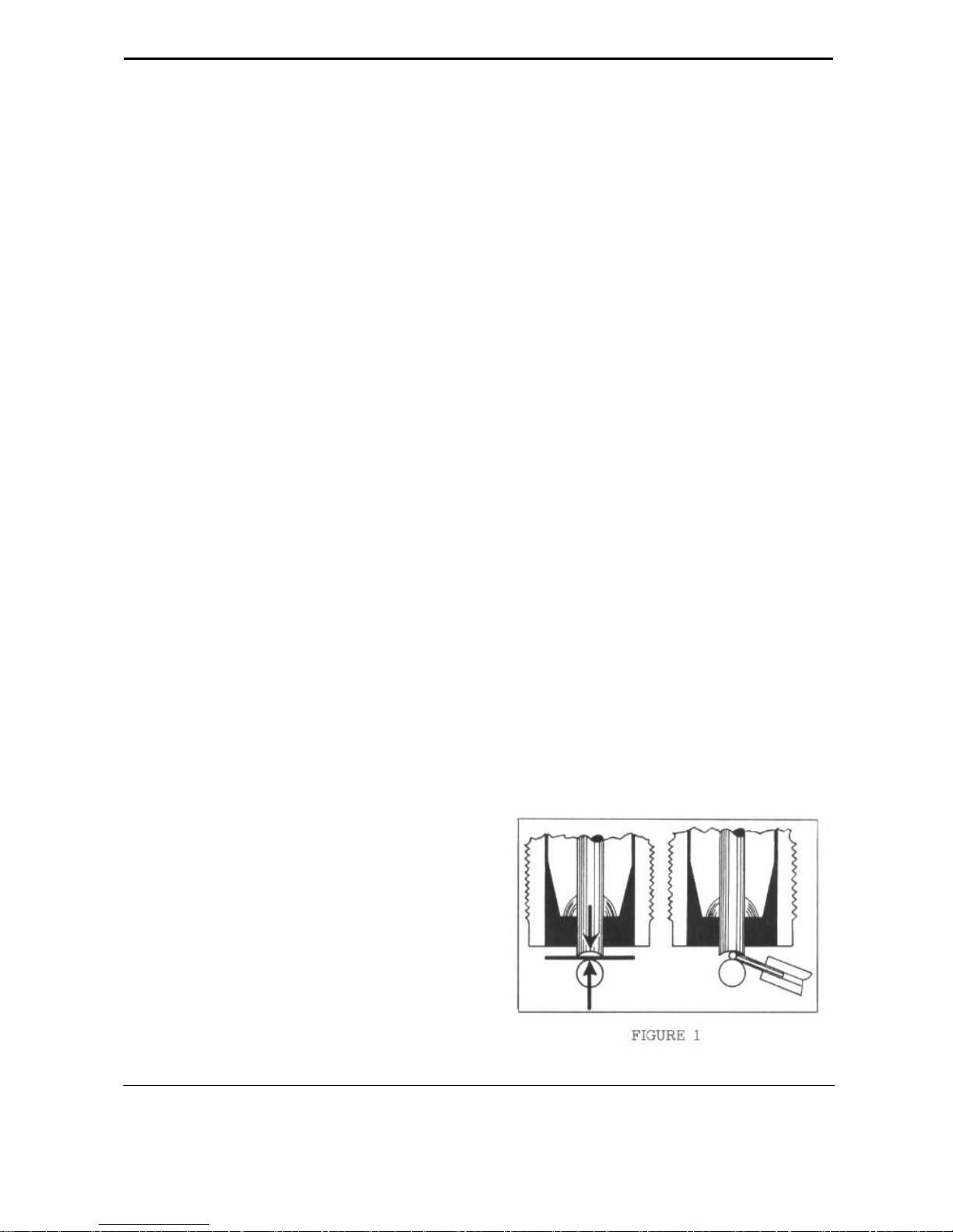
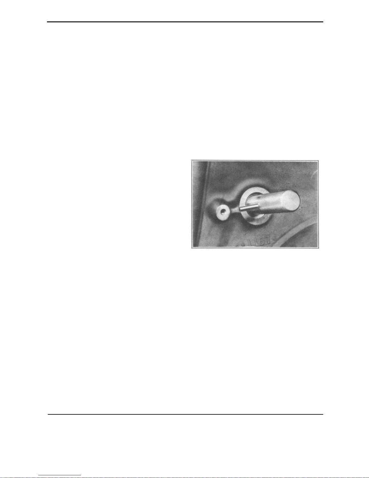
OIL CHECK VALVE
Oil pressure is maintained by a non-adjustable
oil check valve consisting of a plunger, spring,
plug retainer and plug gasket. The assembly is
located in the left side of the crankcase slightly
below the distributor. Oil pressure against the end
of the plunger and spring forces the plunger off its
seat allowing oil to return to the oil pan, Figure 1.
one cylinder. Do not disturb this position of the
engine while the oil pump is removed.
2. Remove the two oil pump to block attaching
screws and remove the oil pump.
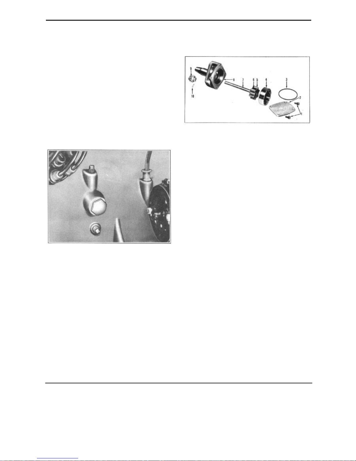
FIGURE 2
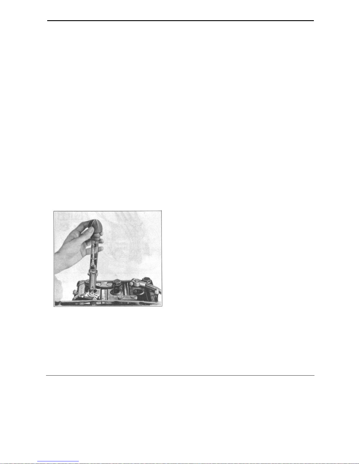
DISASSEMBLY
1. Remove the cover screws (1), Figure 2, cover
(2) and gasket (3).
2. Hold hand over cover opening and with the
pump upside down, turn shaft until the pump
rotor (4) falls out in the hand.
3. Drive out straight pin (10) which holds
pump drive gear to pump shaft.
4. Press shaft (7) out of gear (9) by supporting the
oil pump body (8) on the cover face in an arbor
press allowing the inner rotor and shaft to clear
when pressing the shaft out of the pump gear.
5. Wash all parts in cleaning solvent and dry
with compressed air.
FIGURE 1
OIL PUMP
The oil pump is of simple construction and
very efficient providing high volume. It is a rotor
type pressure pump. Service is seldom required.
REMOVAL
Care must be exercised to maintain correct
engine ignition timing when it is necessary to
remove the pump for servicing. The recommended procedure is as follows:
1. Lift off the distributor cap and rotate the engine
crankshaft until the distributor rotor is in firing
position for the number
INSPECTION
1. Install rotors and shaft in pump body with the
inner rotor located so that one lobe of the inner
rotor contacts the corresponding notch in the
outer rotor. Measure the clearance between the
opposite lobe of the inn e r and outer rotor. This
clearance should be .010" or less. If more than
this, replace both rotors and shaft.
2. With rotors and shaft assembled in the pump
body place a straight edge across the pump
body between the screw holes and using a feeler
gauge, measure the clearance between the top
of the rotors an d the straight edge. This clearance should be .004" or less. If the clearance is
greater than this limit, the pump body must be
replaced.
25 ENGINE
3. With the outer rotor (4) pressed against one
side of the pump body, with a feeler gauge
measure the clearance between the outer rotor
and pump body at the opposite side. If this
clearance is more than .008", replace the pump
body.
4. Body cover (2) should be smooth. It should be
replaced if scratched, grooved or worn. Lay a
straight edge across the inner surface of cover
and check with .002" feeler gauge between the
cover and straight edge. If the feeler gauge can
be inserted, the cover is worn and must be
replaced.
ASSEMBLY
1. Install the outer. rotor (4) in the pump body (8),
Figure 2.
2. Slide the pump shaft (7) and rotor (5) assembly
into the pump body.
3. Support oil pump body, shaft and rotors assembly
on a clean surface and press pump drive gear (9)
on pump shaft (7). End play between the hub of
the drive gear and pump body should be .004" to
.008".
NOTE: The slot in the end of the oil pump
shaft is machined off center as is the tongue on
the end of the distributor shaft, Figure 4.
4. Install the oil pump, engaging the oil pump
drive gear with the camshaft worm gear teeth.
The pump shaft must be aligned to engage the
shaft slot with the tongue on the end of the
aligning tool. Then push the tool out as the
pump is seated against the block mounting
face.
5. Remove aligning tool J-2794'.
6. Set distributor in No. 1 firing position and
install.
7. In stall distributor mounting screw, distributor c a p , distributor vacuum control tube
and connect the coil lead wire.
4. In stall gear pin and peen over both ends
securely.
5. After inspecting to see that pump is thoroughly
clean, install cover gasket (3) in the recess in
the pump body.
6. Install cover (2). Tighten cover screws (1)
evenly and securely.
INSTALLATION
If the engine crankshaft has been rotated inadvertently during the interval the oil pump was out
being repaired, ignition timing will be incorrect.
The following steps will then be necessary to
remedy the improper timing.
1. Remove the distributor mounting screw, dis
connect the distributor vacuum control tube,
disconnect the coil lead wire and remove the
distributor.
2. Set dampener timing with the No. 1 piston on
T.D.C.
3. Insert aligning tool J-2794 in the distributor
shaft hole with the aligning pin in line with the
distributor mounting screw hole, Figure 3.
FIGURE 3
OIL PAN
REMOVAL
1. Raise car and place stand jacks under the No. 2
frame crossmember.
2. Remove the three bolts attaching the center
steering arm support bracket to the No. 2 crossmember. This permits the center steering arm
and tie rods to drop.
3. Remove the two attaching bolts, flywheel dust
cover to bell-housing, and remove dust cover.
4. Remove oil pan drain plug and drain oil. 5. Re-
move bolts and lockwashers attaching oil pan
to cylinder block and remove oil pan.
NOTE: Do not lose the round rubber gasket at
the oil outlet tube.
 Loading...