

Hudson Year 1947, 1947 SUPER SIX, 1947 COMMODORE SIX, 1947 3/4-TON COMMERCIAL, 1947 SUPER EIGHT Owner's Manual
...Page 1
Page 2

Page 3

WHEN YOUR
NEW HUDSON
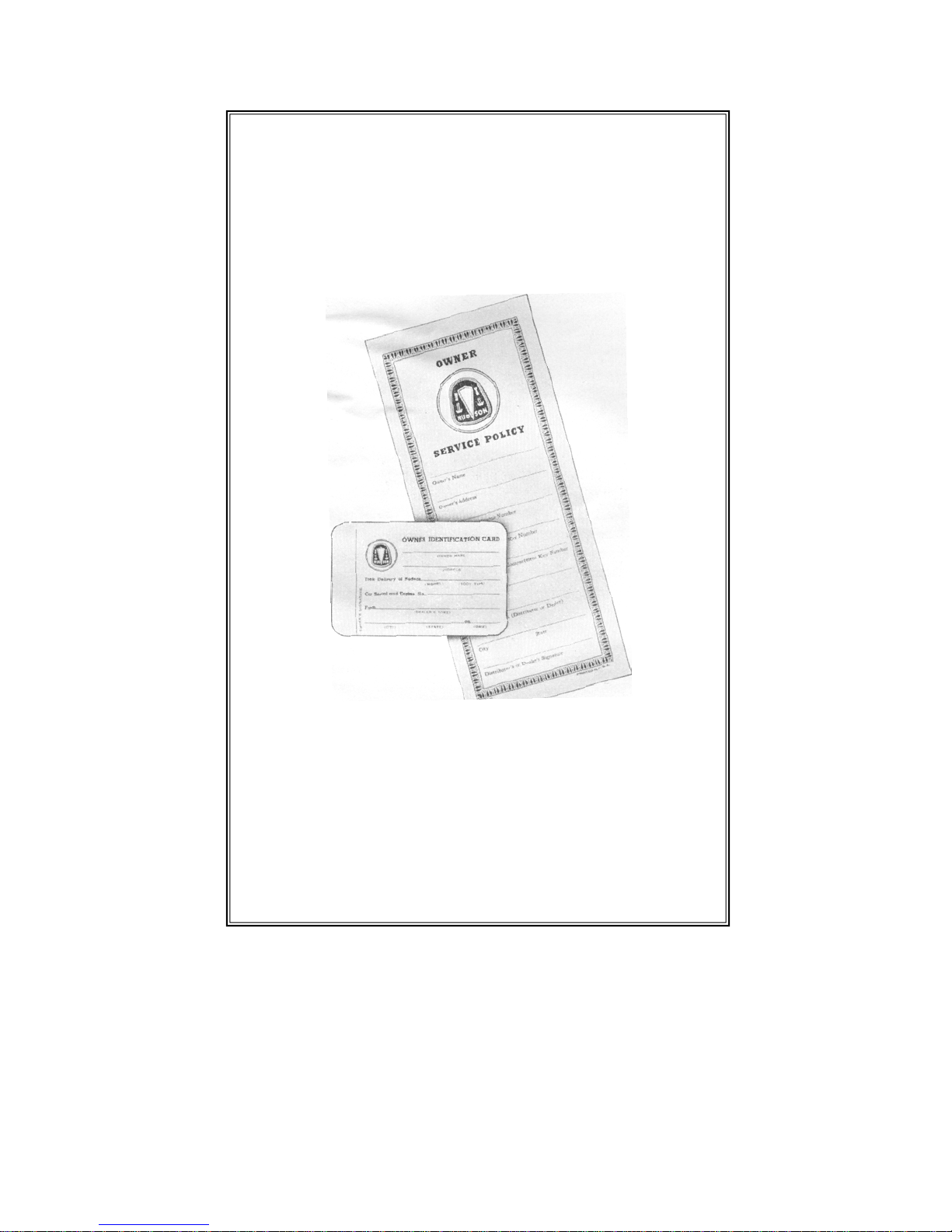
IDENTIFICATION CARD completely filled in on both
sides. BE SURE THAT KEY NUMBERS ARE
IS DELIVERED TO YOU
SEE THAT THESE THINGS ARE DONE
OWNER'S SERVICE POLICY properly filled in and
its provisions fully explained to you.
RECORDED.
BATTERY properly registered with National Battery
Dealer.
RADIO WARRANTY REGISTRATION CARD filled
in by dealer and attached to radio if car is so
equipped.
Page 4

Welcome
As the purchaser of a new Hudson car we welcome
you into the fast growing family of Hudson owners.
This may be your first Hudson—or possibly you have
had previous experience with this fine product. In
either event you will have many pleasant reactions in
Naturally, you will want to keep it trouble free and
derive from it the many pleasures for which it was
pared this Owner's Manual. In its pages you will find
Before you drive your car take a few minutes to study
this manual. It contains a wealth of information--
just the things you will want to know. Then place
its ownership.
purchased. With this thought in mind we have pre-
many suggestions to fully acquaint you with its construction, operating features and maintenance requirements.
it in the locker box for convenient future reference.
HUDSON MOTOR CAR COMPANY
Service Department
Page 5

WARRANTY
judgment of the Manufacturer, to affect its stability
"We warrant each new car manufactured by us to be
free from defects in material and workmanship under
normal use and service, our obligation under this warranty being limited to making good at our factory any
part or parts thereof, including all equipment or trade
accessories ( except tires) supplied by the Car Manufacturer, which shall, within ninety (90) days after
making delivery of such vehicle to the original purchaser, or before such vehicle has been driven 4,000
miles, whichever event shall first occur, be returned
to us with transportation charges prepaid, and which
our examination shall disclose to our satisfaction to
have been thus defective ; this warranty being expressly
in lieu of all other warranties expressed or implied, and
of all other obligations or liabilties on our part, and we
neither assume nor authorize any other person to assume for us any other liability in connection with the
sale of our vehicles.
"This warranty shall not apply to any vehicle which
shall have been repaired or altered by other than an
Authorized Hudson Dealer in any way so as, in the
or reliability, nor which has been subject to misuse,
negligence or accident."
HUDSON MOTOR CAR COMPANY
Detroit, Michigan, U.S, A.
The Hudson Motor Car Company reserves the right to make
any changes in or improvements on its products without incurring any liability or obligation whatever, and without being
required to make any corresponding changes or improvements
on products theretofore manufactured or sold.
Page 6
OWNER'S SERVICE POLICY
sions of the Hudson Owner's Service Policy which was
We cannot too greatly impress you with the need for
reading fully and becoming acquainted with the provi-
furnished with this automobile.
AUTHORIZED
HUDSON SERVICE
STATIONS
HUD
SON
PARTS SERVICE
Page 7
AUTHORIZED
The majority of automobile owners are conscientious in the service
requirements of their cars and unhesitatingly call on their car dealer
for service as and when it is required. These car owners realize that
their Hudson Dealer is in a position to render the satisfactory and
When touring or away from familiar surroundings the occasion may
arise for service needs. Look for the Hudson Authorized Service sign,
illustrated above. The Hudson Dealer displaying this sign is your
assurance of the same efficient, friendly service you receive at home.
It is your further assurance that his Service Department stocks only
HUDSON SERVICE
STATIONS
efficient service to which they are entitled.
genuine Hudson parts; uses factory approved service tools and methods and employs careful and courteous mechanics.
Page 8

6 HUDSON OWNER’S MANUAL
INSPECTION AND ADJUSTMENT SERVICE
The Hudson Owner's Service Policy provides that at the expiration of 1,000
miles and again at 2,000 miles of driving the Hudson Dealer from whom you purchased your car will perform an Inspection and Adjustment Service without
charge, except for supplies or lubricants used.
Should either of these inspections be performed by another Authorized Hudson
Dealer (one who did not sell the car) a charge of not to exceed :$5.00 will be
made for either the 1,000-mile inspection or the 2,000-mile inspection. In this
event the owner should secure a receipted bill and present it with the Owner's Policy to his own Dealer (who sold the car) and that Dealer will provide for one or
two additional inspections, whichever the case may be, without charge, except for
supplies and lubricants used.
We urge you to carefully read the provisions of the Owner's Service Policy so
that you will fully understand this procedure.
The Inspection and Adjustment Service consists of the following :
1,000 Mile
1. Check Operation of All Locks.
2. Check Signals and Instruments.
3. Check Operation of Lights.
4. Check Battery and Connections.
5. Tighten Cylinder Head Stud Nuts.
6. Tighten Manifolds.
7. Check Cooling System and Coolant.
8. Check Clutch Pedal Clearance.
2,000 Mile
1. Check Operation of Signals and In
struments.
2. Check Operation of All Lights.
3. Check Operation of Windshield
Wipers.
4. Inspect Cooling System and Conn-
ections (Anti-Freeze in Winter).
5. Check Battery and Connections
9. Check Axle Shaft Nut Tightness.
10. Check Wheel Hub Bolts.
11. Check Rear Spring Clips.
12. Check Body Bolts.
13. Check Hand and Foot Brakes.
14. Check Drive-Master.
15. Road Test.
6. Adjust Tappets—Engine Hot.
7. Tune-Up Engine.
8. Check Generator Charging
Rate.
9. Check Wheel Hub Bolts.
10. Check Hand and Foot Brakes.
11. Check Drive-Master.
12. Road Test
Page 9

HUDSON OWNER’S MANUAL 7
1947 MODELS
MODEL DESIGNATION AND SERIAL NUMBERS
To simplify identification of the various models referred to in this Owner's Manual, model
reference is made to series numbers listed below.
The car serial number which is also the engine number is stamped on a small plate attached to the
right front door hinge pillar post. These serial numbers are based on a system which codes the first
three digits to the series : e.g. 171101 indicates series 171 while 172101 and 173101 indicate
series 172 and 173 respectively. The first three digits remain unchanged regardless of the number
of cars produced. Cars are also numbered consecutively as they leave the production line without
regard to series. As an example, the car built after car serial 171999 would be numbered 1711000,
1721000, 1731000, 1741000 or 1781000, instead of 172000.
The engine number is stamped on the top of the cylinder block between Nos. 1 and 2 exhaust
manifold flanges.
CAUTION: Do not confuse engine number with casting or other numbers appearing at
different locations on engine.
When ordering service parts or corresponding with your dealer always refer to this number.
Also be sure this number corresponds to the one shown on your Owner's Service Policy,
Identification Card, and Car Registration Card.
The car color option code letter is stamped on the upper hinge of the right front door.
LICENSE INFORMATION
HUDSON SUPER SIX MODEL—SERIES 171
5”
5”
5”
5”
5”
5”
5”
4½
4½
4½
4½
4½
A.M.A.
H.P.
Rating
21.6
21.6
21.6
21.6
21.6
21.6
21.6
28.8
28.8
28.8
28.8
28.8
Body Types
4 Door Sedan
Brougham
3 Pass. Coupe
Club Coupe
Convertible
Brougham
4 Door Sedan
Club Coupe
Cab Pick-Up 6 128” 3” 5” 21.6 178101 3110
4 Door Sedan
Club Coupe
4 Door Sedan
Club Coupe
Convertible
Brougham
The above weights include spare tire, tube and wheel, but do not include water, oil
or gasoline.
No. of
Cyls.
HUDSON COMMODORE SIX MODEL—SERIES 172
HUDSON ¾-TON COMMERCIAL MODEL—SERIES 178
HUDSON SUPER EIGHT MODEL—SERIES 173
HUDSON COMMODORE EIGHT MODEL—SERIES 174
Wheel-
base Bore Stroke
6
6
6
6
6
6
6
8
8
8
8
8
121”
121”
121”
121”
121”
121”
121”
121”
121”
121”
121”
121”
3”
3”
3”
3”
3”
3”
3”
3”
3”
3”
3”
3”
Starting
Serial
No.
171101
and
up
172101
and up
173101
and up
174101
and
up
Dry
Weight
Pounds
3110
3055
2975
3040
3220
3175
2090
3260
3210
3330
3260
3435
Page 10

8 HUDSON OWNER’S MANUAL
TECHNICAL INFORMATION
ENGINE
Series No.
171, 172, 178............... 6 3"
173, 174 ..................... 8 3"
Compression Ratio
All Models
Horsepower (Actual)
171, 172, 178....................102 0 4000 R.P.M.
173, 174.........................128 4200 R.P.M.
Main Bearings (Number)
6 cylinder............................................ 3
8 cylinder............................................ 5
Pistons
Material ..........................Aluminum Alloy
Skirt Clearance—
Bottom................................ .0005" to
.001
CARBURETOR AND FUEL SYSTEM
Carburetor
Make .............................................Carter
Series Size Type
171, 172, 178................l" Duplex Down-draft
173, 174.................13/4" Duplex Down-draft
Choke Control
All
Models...............................Automatic
STARTING, LIGHTING AND IGNITION
Make.......................................................................................................................................Auto-Lite
Generator
Type ..................................................................................3rd brush—voltage regulated
Charging Rate—
Cold—All Models.............................................................................................Max.
Hot—All Models...................................................................Max. 38 Amperes
Distributor
Spark Control. Automatic (Additional
vacuum control on 6 cylinder models)
Contact Point Gap
6 cylinder..........................................020"
8 cylinder..........................................017"
Ignition Timing
6 cylinder.............½" on flywheel B.T.D.C.
8 cylinder......................................................T.D.C.
Firing Order
6 cylinder................................l-5-3-6-2-4
8 cylinder..........................1-6-2-5-8-3-7-4
Cyls. Bore
6.
50 to 1
A.M.A. Piston
Stroke H.P. Displacement
21.6 212 cu. in.
4½" 28.8 254 cu. in.
Oil Rings—
Number ...............................................2
Oil Rings-
Upper—Width ...............................3/16"
Oil Rings-
Lower—Width.......................................5/32"
Compression Rings—
Number ...............................................2
Compression Rings—
Width..................................................................3/32"
Camshaft Drive
Type Silent Helical Gears
Manifold Heat Control Type
All Models .......................................Automatic
Air Cleaner
Standard ..........................................Oil wetted
Optional ............................... .Oil bath
44
Amperes
Spark Plugs
Make and .type...Champion Hudson J-9
Size ..........................................14 M.M.
Point Gap......................................................062"
Battery
Make ........................................National
Dimensions-6 cylinder, Length-10½"
Width-7½”
Height-7
8 cylinder, Length-11¾"
Width-7¼"
Height-713/16"
Number of plates
6 cylinder ........................................51
8 cylinder ........................................57
Terminal grounded..........................Positive
-1 3
/16"
Page 11

HUDSON OWNER’S MANUAL 9
Sealed Beam Type
Semi-floating
Helical bevel
LAMP BULB SPECIFICATIONS
S.C.
S.C.
S.C.
S.C.
S.C.
S.C.
S.C.
S.C.
S.C.
S.C.
S.C.
S.C.
S.C
Volt-
age
6-8
6-8
6-8
6-8
6-8
6-8
6-8
6-8
6-8
6-8
6-8
6-8
6-8
6-8
6-8
6-8
6-8
Position Mazda No. C.P. Base
Headlamp
Bonnet Lamp
Fender Lamp (with Direction Indicator)
Fender Lamp (without Direction Indicator)
Tail and Stop Lamp
License Lamp
Dome Lamp
Generator and Oil Indicator
Clock
Speedometer—Series 171, 173, 178
Speedometer—Series 172, 174
Radio
Direction Indicator
Headlamp Beam
Ignition Lock
Courtesy Lamp
Fog Lamp
Spot Light
55
1158
63
1154
63
88
51
55
51
55
44
51
51
55
88
121lS
1209S
2
21-3
3
21-3
3
15
1
2
1
2
1
1
1
2
15
50
32
D.C.
D.C.
D.C.
D.C.
CLUTCH
Type
Series
Fluid cushioned, cork-insert disc
Disc Size
171, 172 without Overdrive, Vacumotive Drive, and Hudson Drive Master 9”
171, 172 with Overdrive, Vacumotive Drive, and Hudson Drive-Master,
and all 173, 174 and 178 models 10”
TRANSMISSION
Type
Speeds
Gear Ratios
All Models
288.1 to 1
Synchronized Silent Mesh—All helical gear
3 forward-1 reverse
Low
Second
1.82 to 1
High
1 to 1
Reverse
3.50 to 1
TRANSMISSION OVERDRIVE
Final rear axle ratio when car is equipped with Overdrive—All Series
Actual Axle Ratio In Overdrive
4 5/9 to 1 3.28 to 1
4 1/9 to 1 2.96 to 1
FRONT SUSPENSION
Type
Camber
Caster
Toe-in
Independent Coil Spring
½° to 1½°
½º to 1½º
0 to 1/16"
Type
Gear Type
Gear Ratio:
Standard Ratio
Optional Ratio
Standard Ratio with Overdrive
Optional Ratio wlth Overdrive
Standard Ratio with Hudson Drive-Master
Optional Ratio with Hudson Drive-Master
REAR AXLE
Series
172 172 173 174 178
4 l/9
4 5/9
4 5/9
4 l/9
4 5/9
4 l/9
4 l/9
4 5/9
4 5/9
4 1/9
4 5/9
4 l/9
4 1/9
4 5/9
4 5/9
4 1/9
4 l/9
4 5/9
4 l/9
4 5/9
4 5/9
4 l/9
4 l/9
4 5/9
4 5/9
—
4 5/9
—
4 5/9
—
Page 12

BRAKES
Type
Size:
Series
171, 172
173, 174, 178
Lining Clearance .075" Pedal to Floor Board Clearance ¼"
Mechanical Follow-up Clearance 1¼"
Diameter
10"
11"
STEERING GEAR
Width
1¾"
1¾"
Type
Worm and roller tooth
Gear Ratio
6 cylinder
18.2 to 1 8 cylinder 18.4 to 1
CHASSIS DIMENSIONS
Series
171, 172, 173, 174
178
Wheelbase
121"
128"
Over-all Length—Including
Bumpers
171, 172, 173, 174 207"
178 214"
Over-all Height—Free Height
68¾"
171, 172, 173, 174
Over-all Width—Including
Fenders
Froont—All Models 71"
Rear—All Models 72¾"
Series
171, 173
172, 174
178
Cold Hot
Tire Pressures
Size
6.00" x 16"
6.50" x 16"
6.50" x 15"
7.00" x 15" (Opt.)
26 lbs.
26 lbs.
26 lbs.
26 lbs.
TIRES
6.00" x 16"
6.50" x 15"
6.50" x 16"
Front
29 lbs.
29 lbs.
29 lbs.
29 lbs.
171, 173
172, 174, 178
Turning Radius
171, 172, 173, 174
178
Tread
Front—All Models
Rear—All Models
Size
Series
Road Clearance
Front
Rear
95/8" 83/8"
9¾" 8½"
Cold Rear
Rear
30 lbs.
40 lbs.
30 lbs.
30 lbs.
21’ 1"
21’ 10"
56¼"
59½"
Ply
4
4
6
33 lbs.
44 lbs.
33 lbs.
33 lbs.
Gasoline Tank
All Models
Cooling System
6 cylinder
8 cylinder
Engine Crankcase
6 cylinder—dry
—refill
8 cylinder—dry
—refill
Clutch
All Models
CAPACITIES
U. S.
Measure
16½ gal.
13 qts.
18 qts.
5½ qts.
4½ qts.
9 qts.
7 qts.
1
/3 pint
Imperial
Measure
13¾ gal.
10¾ qts.
15 qts.
4½ qts,
3¾ qts.
9 qts.
7 qts.
¼ pint
Metric
Measure
62½ liters
12½ liters
17 liters
5¼ liters
4¼ liters
8½ liters
6½ liters
160 c.c.
Page 13

Present day sustained high speed driving, fast acceleration, and closer fitting
precision machined parts, place chassis and engine lubrication in the category of a
highly specialized operation. A very definite plan of application is necessary to
provide the various working parts with the right amount of the correct lubricant at
the proper time. Quite contrary to ordinary belief one lubricant will not suffice for all
chassis parts. Varying load demands and peculiarities of operation of the various parts
require different types of lubricants to prevent friction and reduce wear to a minimum.
cation specifications for your car, as well as the definite plan of application. This
is your assurance that the lubrication requirements of your automobile will be met
For your guidance a copy of the Chassis Lubrication Chart is attached to the front
cover of this manual. Another quick reference chart will be found on the left side of
the dash in the engine compartment. Following is a Lubrication Schedule covering
the lubrication requirements from 500 to 10,000 miles. Careful study of these charts
The lubricants placed in your car at the time of assembly are of the finest quality
procurable and NEED NOT be changed until the recommended change period
HUDSON OWNER’S MANUAL 11
Transmission
Without Overdrive
With Overdrive
Rear Axle
All Models
Shock Absorbers
All Models
U. S.
Measuure
2 lbs.
3¼ lbs.
2½ lbs.
Front Rear
3¾ oz. (112 c.c.) 6¼ oz (187 c.c.)
Imperial
Measure
2 lbs
3¼ lbs
2¾ lbs.
Metric
Measure
.91 kgs.
1.47 kgs.
1.24 kgs.
LUBRICATION
Your Authorized Hudson Dealer has been provided with the correct factory lubri-
with the greatest care. Be sure to consult him on this most important matter.
and the schedule is recommended.
shown in the Lubrication Schedule has been reached.
LUBRICATIONS SCHEDULE
AT 500 MILES
See "The Proper Engine Oil to Use," page 14.
l,000 MILES
Upper Support Arm Eccentric Bushing..............Viscous Chassis Lubricant2 fittings
Upper Support Arm Pivot Bushing.................... Viscous Chassis Lubricant 4 fittings
Lower Support Arm to Support Pivot
Bushing ............................................................ Viscous Chassis Lubricant 2 fittings
Lower Support Arm Pivot Bushing................... Viscous Chassis Lubricant 4 fittings
Spindle Pivot Pin.................................................. Viscous Chassis Lubricant 2 fittings
Tie Rod End......................................................... Viscous Chassis Lubricant 4 fittings
Steering Center Arm Bearings............................ Viscous Chassis Lubricant 1 fitting
Drag Link ............................................................ Viscous Chassis Lubricant 2 fittings
Clutch and Brake Pedal Shaft Bushings............ Viscous Chassis Lubricant 1 fitting
Drive-Master Transfer Key (Opt. Equip.).........Viscous Chassis Lubricant 1 fitting
Page 14

Clutch Throwout Bearing
Universal Joint Spline
Universal Joint Roller Bearing
Rear Spring Rear Shackle Bushing
Water Pump
Viscous Chassis Lubricant 1 fitting
Viscous Chassis Lubricant 1 fitting
Viscous Chassis Lubricant 2 fittings
Viscous Chassis Lubricant 4 fittings
Aluminum Soap Base Grease 1 fitting or other water-resistant grease
Distributor-6 cylinder
Engine
Battery
Radiator
*Transmission
*Rear Axle
Steering Gear
Brake Master Cylinder
Front Door Hinge Pins
Water Pump Grease Turn grease cup 1
turn
Check Oil Level
Add water if less than % inch above plates
Check Water Level or Anti-Freeze
Check level and add lubricant if necessary
Cheek level and add lubricant if necessary
Check level and add lubricant if necessary
Check level and add fluid if necessary
Light Engine Oil Hole in each lower
hinge
Door Dovetail and Striker
Light Engine Oil Two places each
door
Front Door tipper and Rear Door Lower
Hinge Tension Springs
Striker Pawls
Water Pump Grease. Apply by hand
Pencil lubricant. Coat lightly
2,000 MILES
Perform operations listed under 1,000-mile lubrication in addition to the following:
Engine
See "Proper Oil to
Drain and Refill
Use"—page 14
Generator
Starting Motor
Distributor-6 and 8 cylinder
Distributor-6 cylinder
Light Engine Oil
Light Engine Oil
Water Pump
Grease
Light Engine Oil
2 cups
2 cups
Cam lobes
Contact arm pivot
and wick in top
of rotor shaft
Distributor-8 cylinder
Light Engine Oil
Oil cup, contact arm
pivot and wick in
Throttle Linkage
Bonnet Support and Lock Shaft
Brake Operating Linkage
Carburetor Air Cleaner
•Drive-Master Linkage
•Vacumotive Drive Linkage
Light Engine Oil
Light Engine Oil
Light Engine Oil
Engine Oil
Light Engine Oil
Light Engine Oil
top of rotor shaft
All joints
All joints
All joints
Clean and re-oil
All joints
All joints
5,000 MILES
Perform the operations listed under 1,000 and 2,000-mile lubrication (except change
engine oil) in addition to the following:
Rear Brake Cables Viscous Chassis Lubricant Coat Cables
Distributor-6 cylinder Water Pump Grease Fill Cup
Oil Filter Replace Cartridge
Drain and Refill These Units:
Transmission S.A.E. 90 E.P. Summer 2 lbs.—with
S.A.E. 80 E.P. Winter overdrive 3% lbs.
Rear Axle S.A.E. 90 E.P. Summer and Winter 2¾ lbs.
Clutch Hudsonite
1
/3 pint
• Optional equipment.
Page 15

*Important: When checking transmission and rear axle oil level care should
be taken that the oil foam has subsided. If the car has been run for any length
of time it should be permitted to stand long enough to allow the oil to reach
The S.A.E. 90 E.P. and S.A.E. 80 E.P. gear oils specified should be of a mild extreme
pressure, non-corrosive type. When adding lubricant to or refilling the transmission or
Special "break-in" oils or compounds are not necessary in Hudson engines. Your
decision to use them should be based on the manufacturer's assurance that they contain
The capacity of the oil reservoir in SIX cylinder engines is five and one-half
quarts ; in EIGHT cylinder engines nine quarts. When oil is drained in the
conventional manner, refill SIX cylinder engines with four and one-half quarts of
When the oil reservoir is removed for cleaning, pour one and one-half quarts of oil
into the upper tray of SIX cylinder engines before the reservoir is reassembled.
Then pour the additional four quarts through the oil filler hole. On EIGHT
cylinder engines pour two quarts of oil into the upper tray before reassembling it
It is not unusual to add oil between change periods. Its rate of usage is governed
by the individual engine and is dependent on operating speeds, temperatures,
HUDSON OWNER’S MANUAL 13
Perform the operations listed under 1,000, 2,000 and 5,000-mile lubrication in addition to
Front Wheel Bearings Milled Sodium Base 4 ounces per wheel
Lubricant
Rear Wheel Bearings Milled Sodium Base 1½ ounces per
Lubricant wheel
Spring Covers Viscous Chassis Lubricant
Vacumotive Drive Cylinder Hudson Shock Absorber 1 ounce
(Optional Equipment) Fluid
Drive-Master Cylinder Hudson Shock Absorber 1 ounce
(Optional Equipment) Fluid
10,000 MILES
the following:
its actual level before checking.
rear axle be sure the lubricants used meet these requirements for satisfactory operation.
BREAK-IN OILS NOT REQUIRED
no harmful ingredients.
CRANKCASE CAPACITIES
oil and EIGHT cylinder engines with seven quarts.
to the engine and pour the additional seven quarts in through the oil filler hole.
CHECKING ENGINE OIL LEVEL
viscosity of oil used, etc.
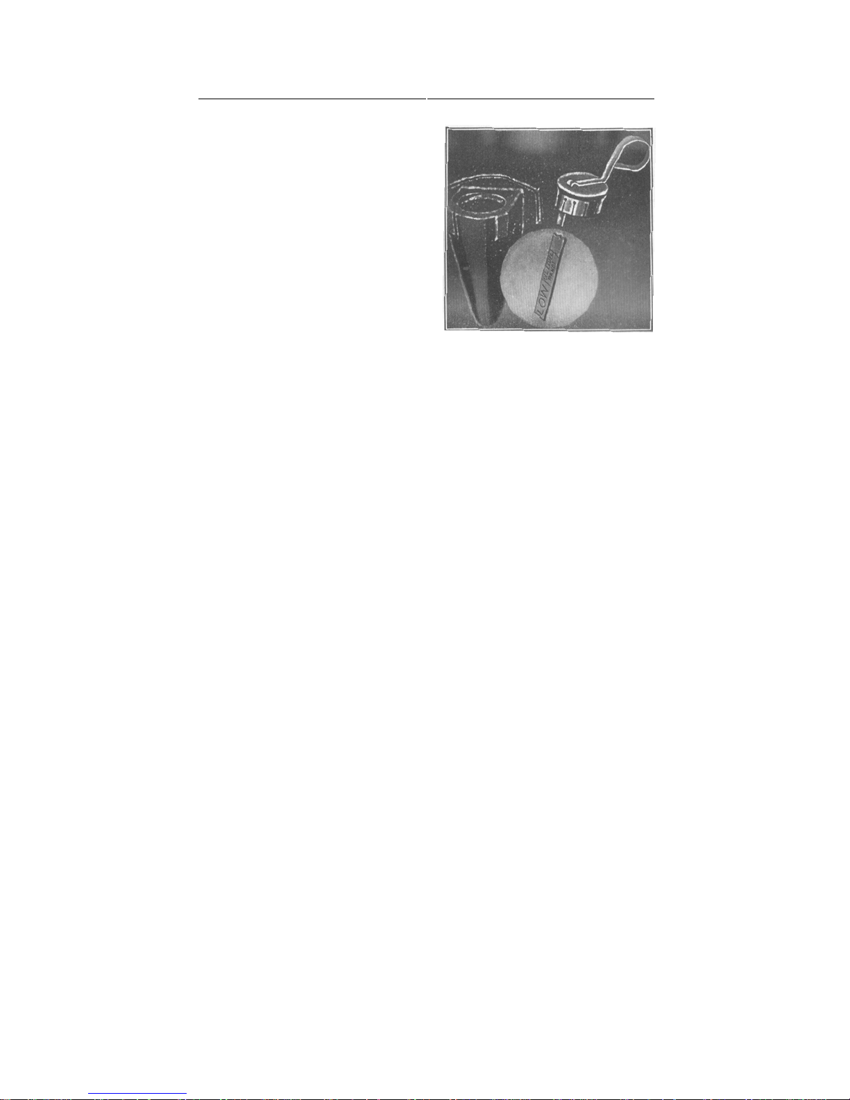
The level should be checked each time f uel is added. The oil gauge, illustrated in
Page 16
placed in the engine at the factory.
14 HUDSON OWNER’S MANUAL
Fig. 1, is located on the left side of the
engine. It is divided off at the lower end
into two divisions — Oil Level Range and
Low.
For normal operation the oil level is
satisfactory when it is within the Oil Level
Range. For high speed operation the level
should be maintained at the full mark, that
is the top line on the Oil Level Range.
To make an accurate check of the oil
level it is best to wait a minute or two after
the engine has been shut off to permit the
oil on the engine parts to drain back into the
reservoir.
Two and one-half quarts of oil are required
Figure 1
to restore the level from low to full in both six and eight cylinder engines. If the level
is low, and the speedometer reading indicates that the oil change period is near at
hand, it is more economical to have the oil changed.
WHEN TO CHANGE ENGINE OIL
During the first 500 miles of driving it is satisfactory to use the oil which was
Thereafter at intervals of 2,000 miles the oil reservoir should be drained and
refilled with the proper grade of oil. If the car is operated constantly in dusty areas or
for short distances at slow speeds in the winter, which permits foreign matter to
accumulate in the oil and contaminate it, the oil should be changed more frequently.
The actual change period, however, depends largely on the individual circumstances.
To drain the oil remove the plug at the rear of the oil reservoir. Always drain the
oil when it is warm as it will then flow more freely.
It is good practice to remove the oil reservoir at least twice a year, preferably in
the fall and spring, to permit cleaning the screens and removing all traces of sludge
which may have accumulated in the lower pan.
Caution: When flushing oils or compounds are used in the engine, it is important
to remove the oil reservoir and thoroughly clean it out before installing the new oil.
THE PROPER ENGINE OIL TO USE
There are two important factors to consider when buying engine oil. The first is
the selection of a well-known, dependable brand. There are many good, well-bodied,
long-lived oils on the market and your selection should be based on the reputation of
the refiner or marketer. He is responsible for the quality of his product and his
reputation is the car owner's best indication of quality.
Page 17
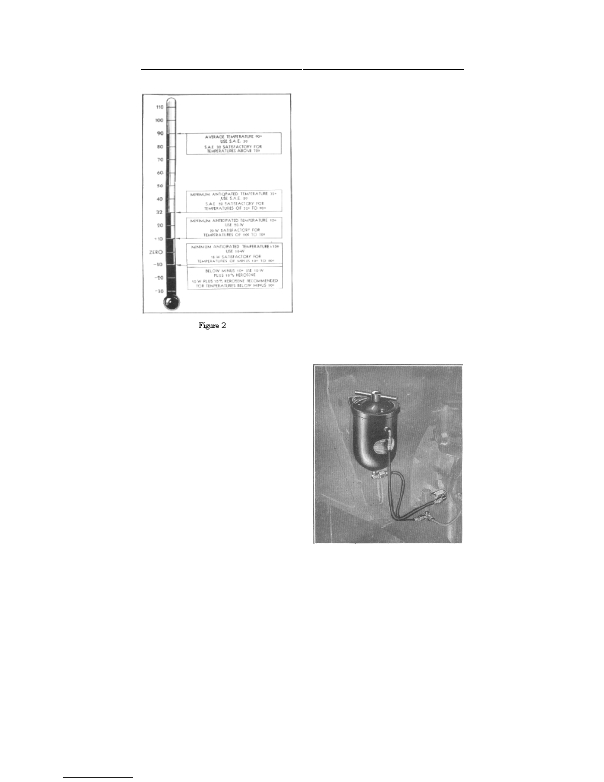
The first requisite is closely related to the
second factor, in that the oil should have the
ability to flow at low temperatures, to permit
easy starting, and at the same time afford ade-
quate lubrication when the engine reaches nor-
mal operating temperatures. The oil used should
be based on its ability to perform these two
functions at the lowest anticipated temperatures
expected before the next oil change period. See
The following table will he helpful in making
Note: Kerosene should be added only when
HUDSON OWNER’S MANUAL 15
S.A.E. 20
20 W
10 W
10 W, plus 10%
Fig. 2.
this selection :
Use
Use 90° Average temperature S.A.E. 30
Minimum anticipated
temperatures
32°
10°
—10°
Below —10°
kerosene.
temperatures below minus 10° are expected for long periods
Your Authorized Hudson Dealer, who has had
long experience with the brands of oils available
in your locality, will be glad to help you with
your lubrication problems
OIL FILTER
A Hudson Oil Filter, see Fig. 3, which aids in
removing foreign matter and impurities under
low pressure, and at the same time maintains a
normal flow of oil through the engine is available
through your Authorized Hudson Dealer. This
filter will keep the oil cleaner for longer periods
and help minimize wear on engine parts.
The cartridge should be replaced every 5,000
to 6,000 miles or whenever the oil shows definite
signs of becoming cloudy. Replacement cartridges should be secured from your Authorized
Hudson Dealer
Figure 3
Page 18
16 HUDSON OWNER’S MANUAL
prevent damage to it and avoid oil leaks.
prevent twisting the hose.
period.
present day automobile are self-evident to the driver, nevertheless a review of their
purposes and operation, and a full knowledge of the newer controls before driving your
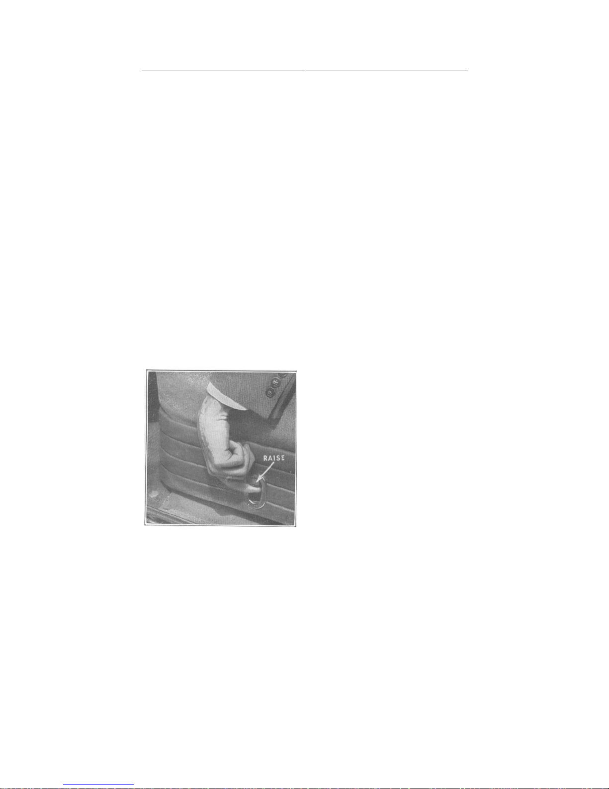
SEAT ADJUSTING LEVER is located
on the left side of the seat to secure fore
and aft movement of the seat for greater
comfort. On long drives, periodically
changing the seat position will prove
restful. The small knob shown in Fig. 4,
is raised with the finger to unlock the
seat. Simply releasing the knob locks it
ACCELERATOR PEDAL (A), Fig. 5,
controls the speed of the car. Never
pump the accelerator when starting the
engine as it will result in flooding. When
starting a cold engine, the accelerator
pedal should be pressed down one-half
1Replace the cartridge by turning the handle on the cover in a counterclockwise direction.
Lift out the old cartridge and replace it with the new one. Be sure to use the new cover
gasket furnished with the cartridge. The gasket must set squarely on the filter body to
Note : Whenever tightening hose connections be sure to
use two
wrenches to
It is also good policy to change the engine oil at this time. Using new oil with the new
cartridge will help keep the oil cleaner for a longer
CRANKCASE VENTILATION
Diluents, consisting mainly of water resulting from condensation and unburned gasoline,
contaminate the engine oil. If these diluents were permitted to remain in the engine oil for
any length of time, early deterioration of parts would result.
In the Hudson engine a ventilating system is provided whereby the diluents are drawn
out of the crankcase by vacuum through ventilator tubes on the right side of the engine.
The violent agitation of the oil by the connecting rod dippers tends to vaporize the water,
unburned fuel and other harmful diluents, allowing them to be withdrawn from the
engine by the vacuum created when the car is in motion.
OPERATING CONTROLS
From year to year new devices are introduced by the automobile industry to make
driving easier, safer, and to provide more comfort. While many of the controls on the
new Hudson will be helpful. It is, therefore, recommended that you carefully read these
instructions.
Figure 4
in position.
way and released slowly. With a warm
Page 19
HUDSON OWNER’S MANUAL 17
quarter to one-half way and hold in this
position when cranking. On cars equipped
with Hudson Drive-Master, Overdrive, or
Vacumotive Drive the accelerator pedal is
used to engage or disengage the clutch for
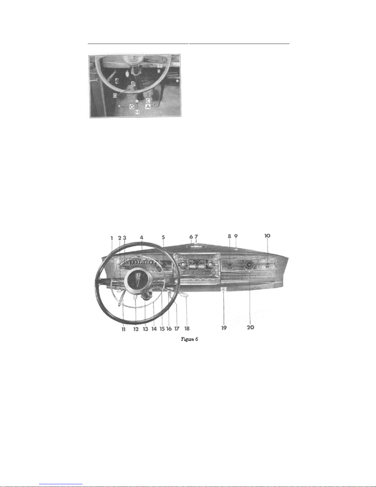
ASH RECEIVER (6), Fig. 6, may be
BONNET LOCKING HANDLE (12),
Fig. 6, should be pushed fully forward to
unlock the bonnet. Pull handle back all the
BRAKE PEDAL (C), Fig. 5, hydraulically operates brakes on all wheels. In event
of disablement of the hydraulic system, continued pressure on the pedal automatically
CLOCK (20), Fig. 6. Mechanical clock requires winding every day. Turn knob
clockwise to wind. Pull knob out to reset. Electric clock requires no attention. Fuse is
CLUTCH PEDAL (D), Fig. 5, should be depressed fully to floor board when
shifting gears. The clutch pedal must be depressed before pressing the starter button
or the starter will not operate on cars equipped with Hudson Drive-Master. When
starting the engine, particularly when it is cold, depressing the clutch pedal manually
will disconnect the load of the transmission from the starting motor and facilitate
engine, depress the accelerator pedal one-
gear shifting.
opened by lifting the knob.
Figure 5
way to lock it.
applies the brakes on the rear wheels mechanically.
located in back of clock. Pull out knob to reset.
starting.
Page 20

COURTESY LAMPS, at bottom of door lock pillar, are standard on Series 172 and
174. These lamps are lighted by switches operated by the doors when they are opened, day or
COWL VENTILATOR HANDLE (17), Fig. 6, should be pushed forward to open
DIRECTION INDICATOR (2) is optional on all models. Push lever up for right
turn and push it down for left turn. Lever returns to off position automatically when
turn is completed. Pilot light (1) on instrument panel flashes with front and rear indicator
DRIVE-MASTER (optional equipment) control switch. Pressing in "HDM" button
permits operation with Hudson Drive-Master. Pressing in "VAC" button permits
power clutch operation with conventional gear shifting. Pressing in "OFF" button
permits conventional operation of clutch and gear shifting. For more complete details, see
page 51. Control buttons are located at lower center on face of panel.
FRONT DOME LAMP SWITCH (Series 172 and 174) is of the sliding type located
FUEL GAUGE (3) indicates the fuel level in the gasoline tank when the ignition is
turned on. When needle reaches empty mark, approximately 2 gallons of fuel remains in
GENERATOR CHARGING INDICATOR (10) shows red when ignition is turned
on or when engine is idling at low speed. Light should go out as speed is increased. If
difficulty is encountered in the electrical system or generator is not charging, the light will
either flash or stay on as a warning. Have the electrical system checked by your nearest
HAND BRAKE HANDLE (11), Fig. 6, should be applied by pulling straight back
and at the same time depressing the brake pedal. Release by turning 1/4 turn to right
HEADLAMP BEAM INDICATOR (4), Fig. 6, shows red when heal lamp beam
HEADLAMP FOOT SWITCH (G), Fig. 5, controls country (upper) and traffic
(lower) beams. When meeting oncoming traffic and headlamp beam indicator shows red,
depress foot switch once and release for lower beam. Pressing switch the second time restores
HORN BUTTON RING (14), Fig. 6 (Opt. equipment on Series 171, 173, and 178 ;
LIGHTING SWITCH (19) controls instrument lights, headlamps, bonnet lights,
fender lamps, tail and license lamps. Pressing button once and releasing it turns on
instrument lights, bonnet light, fender lamps, when used, tail and license lamps. Second
position of button turns on headlamps in addition to other lamps previously lighted.
18 HUDSON OWNER’S MANUAL
night.
ventilator and pulled back to close it.
signals.
DOOR LOCKS—see page 63.
at bottom of instrument panel on right side.
reserve.
Authorized Hudson Dealer.
and pushing downward as far as it will go.
is in upper or country driving position.
beam to upper position.
std. on Series 172 and 174). Press down from any position to operate horns.
IGNITION SWITCH (15) key should be turned to the right to turn ignition "on."
Pressing the button the third time turns off all lights.
Page 21
HUDSON OWNER’S MANUAL 19
LOCKER BOX LOCK (9) is opened by pressing down to open door. Lock by inserting
OIL PRESSURE INDICATOR (8) shows red when ignition is turned on and engine is
not running. Light should go out when engine is started. Should the light flash or stay on when
the engine is running it indicates lack of oil in the reservoir, or some derangement of the
OVERDRIVE CONTROL KNOB (Opt. equipment). Push knob in for overdrive
operation and pull it out for conventional driving. See page 49 for more complete details.
RADIO FOOT SWITCH (H), Figure 5, (optional equipment). Press lightly to reduce
RHEOSTAT (13), Figure 6, located at bottom of instrument panel, is standard on Series
172 and 174. It controls the brilliancy of instrument lights. Turning knob to right decreases
SPEEDOMETER MILEAGE INDICATOR shows accumulated mileage. It is
STARTER SWITCH BUTTON (16) must be pressed in to operate starting motor.
The clutch pedal must be depressed before pressing the starter button or the starter will not
operate on cars equipped with Hudson Drive-Master. Do not press button when
engine is running, or car is in gear. Switch will not operate unless ignition is turned on.
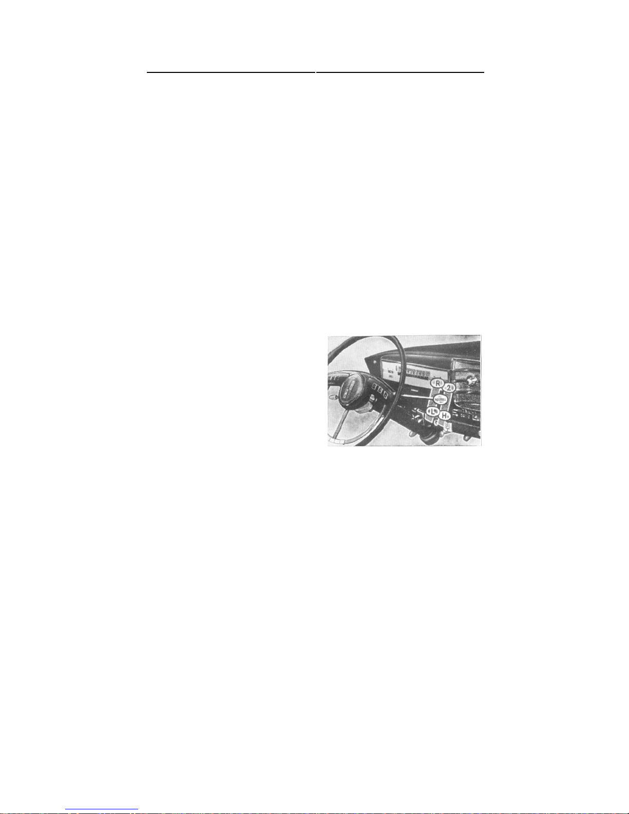
TRANSMISSION CONTROL LEVER (Handy Shift), Fig. 7, should always be
placed in neutral position before starting en-
perature of cooling fluid only when ignition
tional to automatic clutch operation press the "VAC" button located at lower center on face
oughly to be sure that all adjustments were in order ; that all lubrication fittings and units
key and turning it 1/4 turn counter-clockwise.
oiling system. Engine should be stopped at once and source of difficulty determined.
volume and press hard to change station.
light and turning it to the left increases brilliancy. Extreme left position turns out instrument lights.
located below the speedometer.
gine. For cars with Hudson Drive-
Master, see page 51. Raise knob and
move it forward for reverse gear and rearward for low gear. Move to neutral, depress
and slide it forward for second gear and
rearward for high gear.
WA T E R T E M PE R A TU R E
GAUGE (5), Fig. 6, indicates tem-
is turned on. Needle returns to "H" position
at right side of dial when ignition is turned
oil.
Figure 7
WINDSHIELD WIPER KNOB (7)
should be turned to the left to operate wipers.
VACUMOTIVE DRIVE CONTROL (optional equipment). To change from conven-
of panel. Revert to conventional by pressing the "OFF" button. Refer also to page 46.
DRIVING YOUR NEW CAR
Before your new Hudson automobile was delivered to you, your Dealer checked it over thor-
of the car were properly lubricated ; that the cooling system was filled to the proper
Page 22

At the time your car was built, a speed governor was installed on the carburetor and sealed
to restrict top speed and fast acceleration during the initial break-in period. This governor
When the speedometer indicates 500 miles, the car should be returned to your Dealer to
have the governor removed. There is no charge for this service. At this time the engine oil
should be changed, as car speeds will be increased from this point and it is good practice
Although the governor has been removed it does not necessarily mean that the bars
should be let down on car speed. The first 500 miles is commonly called the initial
break-in period. Until the car has been driven at least another 1,000 miles it should be
driven at moderate speeds to give the close fitting, precision machined working parts an
opportunity to assume smooth operating surfaces. The following table will be helpful in
All models are fitted with automatic choke type carburetors. The automatic choke
proportions the correct mixture of air and gasoline for starting and warm-up period.
NOTE : The clutch pedal must be depressed before pressing the starter button or the
starter will not operate on cars equipped with Hudson Drive-Master.
Before starting the engine be sure the Handy Shift transmission control lever is placed
in neutral position (this applies to all models). Depress clutch pedal to release load of
transmission. Turn on ignition switch. If engine is completely cold from standing for
several hours or overnight, depress the accelerator pedal at least half way and release
slowly. Then press starter button. Depressing the accelerator pedal in this manner places
the throttle in proper position for cold starting. This will result in a higher than normal
engine idle speed. Depressing the accelerator pedal again slightly and releasing it will
permit the engine to run at the normal high idle speed to prevent stalling during the warm-up.
Do not allow the engine to run continuously at the starting speeds as it will load up and
stall if left for a minute or two.
If the engine is warm from previous running and has not been standing long enough to
become completely cold, depress the accelerator pedal one-quarter to one-half way and hold
20 HUDSON OWNER’S MANUAL
level, and that the tires were inflated to the proper pressures.
causes a slight increase in carburetor intake noise as long as it is in place.
to have clean, fresh oil in the engine.
guiding you as to the highest speeds that should be attained.
0— 250 Miles—Do not exceed 40 miles per hour in high gear.
250— 500 Miles—Do not exceed 50 miles per hour in high gear.
500— 1000 Miles—Do not exceed 60 miles per hour in high gear.
STARTING THE ENGINE
in this position while cranking. Then press starter button.
Should the engine fail to start when following these instructions, it may be due to-
1. Improper engine tune-up.
2. In cold weather, improper lubricants.
3. A combination of 1 and 2.
Page 23
REAR COMPARTMENT DOOR—To safeguard the spare tire, tools,
and any luggage that you may be carrying, always lock the rear compartment
HUDSON OWNER’S MANUAL 21
In such an event it is recommended that you consult your Authorized Hudson Dealer.
CARBON MONOXIDE GAS
CARBON MONOXIDE, A DEADLY, COLORLESS, ODORLESS
GAS IS ALWAYS PRESENT IN THE EXHAUST OF THE INTERNAL COMBUSTION ENGINE. GARAGE DOORS SHOULD
ALWAYS BE FULLY OPENED WHEN STARTING OR RUNNING
THE ENGINE.
LOCKING YOUR CAR
When your car was delivered to you it was provided with two sets of keys. The
keys with round handles fit the ignition and both front door outside locks. The keys
with the octagonal shaped handles fit the locker box door and rear compartment
locks.
All keys are numbered and these numbers should be registered on your Ownership Card
as well as some other suitable place where they will be available should the keys become
lost. As insurance regulations prohibit the stamping of key numbers on lock cylinders, misplaced or lost keys can be obtained from your Hudson Dealer only by
referring to key change number.
Many cars are driven away by unscrupulous persons simply because the ignition
key was left in the lock. Make it a practice to remove the key from the lock if the
car is to be left unattended even for only a few minutes. This is also assurance
against accidentally locking yourself out of the car.
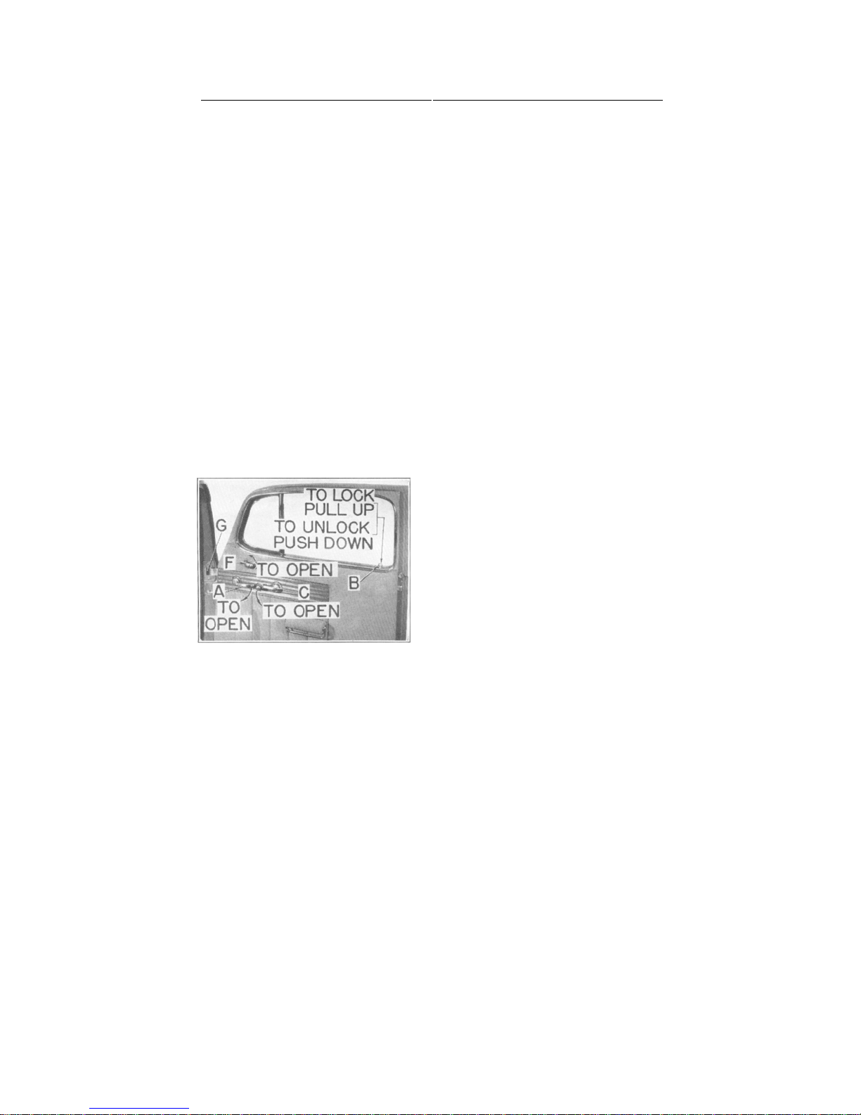
DOOR LOCKS—All doors can be locked from the inside by pulling up on the rubber
knob (B) protruding from the door finish
moulding, see Fig. 8. To unlock the door
press down the knob. Both the right and left
front doors may be locked or unlocked
from the outside with the ignition switch
key. Turning the key one-quarter turn in a
clockwise rotation and back to the starting
position locks the door. To unlock, turn the
key one-quarter turn in counter-clock-
wise rotation and then back to starting
position.
LOCKER BOX DOOR—To lock the
Figure 8
door turn key one-quarter turn clockwise and
remove key. To unlock it turn key onequarter turn counter-clockwise and remove
key.
When door is unlocked it can be opened by pressing down on lock cylinder face.
Page 24

22 HUDSON OWNER’S MANUAL
handle. Turning the key one-half turn clockwise unlocks the lock. To lock it turn
the key one-half turn in counter-clockwise rotation.
To open the rear compartment door grasp the handle and turn it to the right. To
prevent damaging the lock be sure the handle is held to the extreme right when closing
the door.
LOCKING THE BONNET
The bonnet on your car is designed to
prevent it from being blown open if the
locking handle is accidentally left unlocked, and to prevent the engine parts and
accessories being tampered with when
locked.
To raise the bonnet first unlock it by
pushing forward on handle, Fig. 9. Then
grasp the bonnet upper moulding at the
rear end and raise the bonnet. Strong,
self-locking supports hold the bonnet it’s
raised position.
To lower the bonnet, pull it
Figure 9
downward and then draw the handle back and nap it into place.
TIRES
INFLATION PRESSURES
Maintaining proper tire pressures is important in obtaining maximum tire life,
proper car handling, and best riding qualities.
Because tires get hot due to frictional contact with the road surface and internal
friction within the tire, tire pressures will increase as much as three to four pounds.
As it is hard to check and maintain proper pressures when tires are hot, always make
it a point to check and inflate them when they are cold. Both cold and hot pressures are
given. Cold pressures should be used when the car has only been driven a few
blocks to the service station. Hot pressures should be used when the car has been
driven at high speed and if the tires are warm to the hand.
Ordinarily tire pressures should be checked at least once a week. However, when
touring, or if the car is driven extensively, they should be checked every morning
before starting out.
Tire valve caps should be finger tight to prevent loss of air which may be escaping
from a leaky valve and also preclude the possibility of dust and dirt getting into
the valve. Replace missing valve caps promptly.
Recommended tire pressures are as follows :
Front Rear
Size Cold Hot Cold Hot
6.00" x 16"
6.50" x 16"
6.50" x 15"
7.00" x 15" (Opt.)
26 lbs.
26 lbs.
26 lbs.
26 lbs.
29 lbs.
29 lbs.
29 lbs.
29 lbs.
30 lbs.
40 lbs.
30 lbs.
30 lbs.
33 lbs.
44 lbs.
33 lbs.
33 lbs.
Page 25

HUDSON OWNER’S MANUAL 23
MINIMIZING TIRE WEAR
To obtain maximum tire life it is good practice to
change tire positions at intervals of from 2,500 to 3,000
miles. This involves placing the left front tire and wheel
assembly on the left rear hub, moving the right front
assembly to the spare wheel carrier, right rear to left
front, left rear to the right front and the spare to the
right rear hub. Switching the tires in this manner changes
their direction of rotation and equalizes the tread wear over
5 tires instead of 4.
TIRE AND WHEEL BALANCE
Proper tire and wheel balance is essential to prevent
low speed thumping and high speed wheel tramp, both of
which contribute to poor handling, certain riding discomforts and excessive
wear of front end parts. Tires and tubes are balanced at the time of assembly
at the factory. The balancing marks are indicated on the tire by a small red
mark. Whenever a tire is removed from the wheel it should always be reinstalled
with the red mark aligned with the valve stem.
Although tires and wheels are balanced when they leave the factory, subsequent
tire wear causes them to go out of balance. To maintain proper balance and
assist in prolonging tire life, it is the tire manufacturers' recommendation that
the wheel and tire assemblies be checked for balance every 2,500 miles and
whenever a tire ha repaired or recapped. Your Authorized Hudson Dealer has the
necessary equipment to perform this work.
DISMOUNTING AND REMOUNTING TIRES
TO DISMOUNT—Deflate the tube completely. Stand on the tire with both feet
to force the bead away from the rim. Push the valve stem back into the tire. With
two tire tools inserted about eight inches apart between the bead and the rim,
raise the bead over the rim. Be careful not to pinch the tube with the tools. With
one tool in position, move the other tool around the rim and remove the remainder
of the bead. Then remove the tube.
Stand wheel in upright position with inner bead in rim well. Apply liquid soap
around both sides of rim. Insert both tire tools between bead and rim and pry tire
out of rim.
TO REMOUNT TIRE—Coat both beads of tire with liquid soap to help
slide them over the rim. Inflate tube just enough to round it out, then insert it
in the tire, placing the valve stem directly in line with the red balancing mark
on the tire. Place the tire on the wheel, carefully guiding valve stem into the hole
in the rim. Push the inner bead over the rim and into well at valve stem and force
balance of bead over the rim. It may be necessary to force a small remaining
portion of the bead over the rim with the tire tool.
Insert the tire tool between outer bead and rim at a point opposite
the valve stem and work bead over the rim. Leave tool in place and work
Page 26

Engage the lifting lug of the jack on the bottom of bumper bar and between the
24 HUDSON OWNER’S MANUAL
other tool around bead and force remainder of the bead over the rim. Be careful not
to damage the tube with the tool.
Inflate tire slowly, carefully checking beads to see that they both are seating properly
on the rim. The tire may be centered by bouncing it a few times. Inflate tire to
recommended pressure.
TOOL KIT
The tool kit is stored in the rear compartment. It contains a wheel hub bolt wrench,
which can also be used as a jack wrench or as a jack handle, pliers, screw driver, and a
ratchet type or a screw type bumper jack and base. Cab Pickup models are provided
with an axle lift type jack with handle extension.
SPARE TIRE AND WHEEL
To remove the spare tire and wheel mounted in the well in the rear compartment,
take out the clamp bolt and clamp, using the wheel hub bolt wrench. Tilt the top of
the tire slightly to the left and remove it from the well.
On models on which the spare tire and wheel is mounted on the partition board, behind
the front seat, remove the clamp bolt and clamp, using the wheel hub bolt wrench and roll
the tire out of the body.
USING THE BUMPER JACK
Set the parking brake securely and apply blocks at wheels to prevent any movement
of car. The jack should be placed on a level and solid place with lifting shaft as near
vertical as possible.
The lift on the bumper must be from the point where it is mounted to the frame and
amply strong to carry the car weight. Figure 10 shows the correct position of jack at
the front or rear bumper.
inner and outer mounting bar bolts on bumper
bar. CAUTION : Do not attempt to engage
jack or raise the car from the ends of bumpers.
Raise the car sufficiently to lift the tire off
the ground by using the crank shaped hub bolt
socket wrench as a handle for the ratchet type
bumper jack.
USING THE AXLE JACK
The axle lift jack should be placed under
the front suspension control arm as near to the
wheel as possible. The rear end is raised by placing the jack under the rear spring pad. Raise
the jack by placing the crank extension in the jack
and rotating the extension clockwise with the
hub bolt wrench.
Figure 10
Page 27

HUDSON OWNER’S MANUAL 25
CHANGING THE WHEEL AND TIRE
Before raising the car, remove the hub cap with a screw driver and with the hub
bolt wrench (jack wrench) loosen the hub bolts one turn. Raise the car sufficiently to
clear the ground and then remove all hub bolts and take off tire and wheel.
When installing the spare, be sure the pilot stud in the hub is in the top position, then
slide wheel onto hub using pilot stud as a guide. After wheel has been installed and car
lowered, again check tightness of hub bolts and replace hub cap.
ENGINES
THE ENGINES used in six and eight cylinder Hudson cars are of "L" head type,
designed for maximum efficiency and smoothness of operation. Live rubber cushions
are used at both front corners and at the rear center of the engine to provide flexibility
in the engine mountings. These cushions prevent engine sound or vibrations from being
transmitted to the chassis and body.
THE CRANKCASE AND CYLINDER BLOCK, cast integrally for maximum rigidity, is of high chrome iron alloy. The use of this hard material permits
seating the valves directly in the block which allows better transfer of heat from the
valve seats. Valve life is accordingly prolonged and frequent valve grinding is unnecessary.
THE PISTONS are of cast aluminum alloy, cam ground and are closely fitted in
smoothly finished cylinders.
PISTON RINGS are of the pinned type, to prevent ring rotation and permit their
maintaining greater efficiency over a longer period of operation.
TWO COMPRESSION RINGS and one oil ring are assembled above the piston
pin and one wiper oil ring is located below the piston pin. The compression rings are
specially processed to promote quick seating and freedom from scuffing.
THE PISTON PINS are of the full floating type, pressed in the diamond bored pin
bosses. Round spring steel lock rings set in grooves in the bosses hold the pins in place.
THE CONNECTING RODS are of drop-forged steel, I-beam construction, shimless type, with lower end bearings of spun bearing alloy. Integral dippers on the lower
ends of the rods passing through the oil troughs serve to circulate the oil, by splash,
throughout the engine.
PISTONS AND CONNECTING RODS are selected for uniform weight to
assure engine balance. They may be removed from the top on six cylinder models and
from the top or bottom on eight cylinder cars.
THE CRANKSHAFT is of heavy drop-forged steel with integral counterweights. It is balanced both statically and dynamically to maintain maximum bearing
life and smoothness of operation. A vibration dampener pressed on and keyed to the
front end of the crankshaft dampens out torsional vibration.
Page 28

pump, a check valve located at the right rear corner of the engine, accessible
pan.
26 HUDSON OWNER’S MANUAL
THE CRANKSHAFT BEARINGS are of the shimless, bronze back, bearing
alloy type. They are attached to the crankcase and caps with brass screws. Three
bearings are used in six cylinder engines and five in eight cylinder engines.
THE CAMSHAFT is of electric furnace alloy, specially processed for maximum life and quiet valve operation.
CAMSHAFT BEARINGS are of the large steel-back, babbitt-lined, replaceable
type. Three bearings are used in six cylinder engines and five in eight cylinder
engines.
VALVE TAPPETS are of the roller cam type and operate in replaceable guides
clamped in the cylinder block. They are adjustable to maintain proper valve
operating clearances.
VALVES. Exhaust valves are of silchrome alloy steel to withstand the high
temperatures encountered. The intake valves are of nickel chromium steel. Both
exhaust and intake valves operate in replaceable guides.
TIMING GEARS are of silent helical tooth design. The camshaft gear is
attached to the front face of the camshaft by three cap screws. The crankshaft gear
is of cast iron and is pressed on and keyed to the front end of the crankshaft.
FLYWHEEL is of highly polished cold rolled steel, closely balanced to assist in
maintaining smooth engine performance. The starter gear is pressed on the flywheel and is replaceable.
VALVE TAPPET ADJUSTMENT
Valve tappets are adjustable to provide correct operating clearances.
Correct valve clearance for six cylinder engine is .010" on intake and .012" on
exhaust. The eight cylinder engine valve clearance is .006" on intake and .008" on
exhaust valves.
Measurement should be made with flat feeler stock of the proper thickness and
with the engine idling at normal operating temperature.
Valve locations, counting from the front, are as follows:
Model Exhaust Intake
6 cylinder l-3-6-7-10-12 2-4-5-8-9-11
8 cylinder l-4-5-8-9-12-13-16 2-3-6-7-10-11-14-15
ENGINE LUBRICATION
The Duo-Flo or double circulating lubrication system is employed in all Hudson
engines. This provides adequate, positive lubrication under all operating conditions.
The system consists of a large capacity, gear driven oscillating plunger oil
external oil lines and an oil reservoir having an upper tray in addition to the storage
When the engine is started the oil pump immediately draws oil from the lower
reservoir and delivers it positively to the front and rear ends of the engine from
whence it is poured into the front and rear troughs of the oil reservoir upper tray.
The action of the connecting rod dippers
Page 29

HUDSON OWNER’S MANUAL 27
Page 30

passing through the oil in the troughs causes it to be violently sprayed against the inside of the
crankcase. The mist thus created heavily coats all working parts, providing them with a
protective film of oil. See Fig. 11. A portion of this oil is caught in channels cast in the side
of the crankcase and is fed by gravity into large reservoirs located directly over the crankshaft
and camshaft bearings. The rotating action of the crankshaft and camshaft draws the oil into the
The overflow of oil from the front and rear troughs toward the center of the engine
provides oil to the adjoining troughs. As this oil reaches the center of the tray it is
returned to the lower reservoir where it is cooled and strained by circulating through a
A pressure pump circulating type cooling system, incorporating thermostatic control, is
Series 171, 172, 173 and 178 use the choke type thermostat which is located in outlet (C),
pump, is equipped with a by-pass type thermo-
pump and back into the cylinder blo ck.
of the drain cock located a I the lower left corner of the radiator, counter-clockwise. To
drain the complete cooling system also remove the pipe plug located at the left rear
corner of the cylinder block. Note: If it becomes necessary to drain the radiator when it
contains anti-freeze and it is desired to save it, a 7/16" inside diameter hose may be fitted
PROPER CARE of the cooling system is highly essential to maintain efficient engine
operation. Rust and scale in the cylinder block is a natural product of water and iron.
Therefore, unless the necessary precautions are taken to prevent this accumulation, which acts as an
insu-
28 HUDSON OWNER’S MANUAL
bearings, affording a constant, positive supply of lubricant.
series of labyrinthian passages and fine mesh screens.
COOLING SYSTEM
used on all Hudson models.
Fig. 12, and prevents circulation of the coolant through the radiator core until such
time as the water reaches a temperature of 150°
to 155°, when the thermostat begins to open.
At 185° the thermostat should be fully opened.
The path of water circulation is as illustrated.
Series 174, which uses a by-pass type water
stat, located in outlet (D ), Fig. 13. This type
thermostat, although restricting water circulation through the radiator core, does permit circulation through the by-pass (C) in the
This t hermostat also begins to open
at 150° to 155° and is fully opened at 185°.
Figure 12
TO DRAIN the radiator only, turn handle
over the end of the drain cock and the loose end placed in a container.
Page 31

HUDSON OWNER’S MANUAL 29
lator, so-called "hot spots" may result
through the inability of the water to cool
the cylinders and the area adjacent to the
valve seats.
The use of Hudson Rust and Corrosion
Inhibitor in the cooling system prior to
adding anti-freeze in the fall and after
draining in the spring will assist to a
large measure in keeping the system clean
and permit efficient circulation. This
product is available through all Authorized Hudson Dealers.
Reverse flushing is an approved method
of removing foreign accumulation from
the radiator core and water jacket in
Figure 12
the cylinder block. As this method requires the use of special equipment, it is recommended that the work be performed
by your Authorized Hudson Dealer.
FAN BELT
The fan belt, Fig. 14, is of the "V" type and drives the water pump and generator through the vibration dampener pulley.
The belt is adjustable by means of a swinging generator mounting. Moving
the generator away from the engine increases the belt tension while moving it
towards the engine decreases its tension. Belt adjustment is correct when it is
possible to depress the belt approximately 3/4", as shown in the illustration.
Page 32

prepar ing for wi nter operation it is
Figure 15
30 HUDSON OWNER’S MANUAL
Adjustment is made by loosening cap screws and nuts (D), (E), and (F).
When proper position has been obtained be sure to tighten screws
and nuts.
WATER PUMP
A six vane impeller packless type water pump, Fig. 15, driven by the fan belt,
is used on all models. No attention, other than periodic lubrication is required.
LUBRICATION — At intervals of 1,000
miles the water pump should be lubricated
through the metered grease fitting, located on
the top of the body, with a high grade
aluminum soap base lubricant, or other suitable water resistant grease.
ANTI-FREEZE
Before installing any anti-freeze when
good practice to always drain and flush the
cooling system to insure unrestricted circulation. Also carefully check all hose and gaskets
for leaks or signs of deterioration.
The use of Hudson Anti-Freeze,
available through all Authorized Hudson
Dealers, is recommended, as it adequately
meets all the requirements of a good, reliable
anti-freeze.
Avoid the use of anti-freeze solutions containing calcium salts, or other
ingredients which promote electrolytic action. Glucose and honey clog the
radiator ; kerosene and fuel oil when hot expel inflammable vapors and,
therefore, solutions containing these ingredients should never be used.
The following anti-freeze table will be helpful in determining the quantity of
anti-freeze required for proper protection :
6-CYLINDER MODELS
Hudson
Anti-Freeze
Temper-
ature U.S. Imp.
+20°
+10°
0°
-10°
-20°
-30°
+20°
+10°
0°
-10°
-20°
-30°
Quarts
2½
3¼
4½
5
5¾
6½
3½
5¼
6¼
7
8
9½
Liters
Metric U.S. Imp.
2½
3¼
3¾
4¾
5½
4½
5¼
6½
2½
3½
4¼
4
4¾
5
6
3
31/
3
5
6
8
6
6½
7½
9
Ethylene Glycol
(Prestone or Equivalent
Quarts
2
3
4
5
5½
6
8-CYLINDER MODELS
3
4½
6
7
7¾
8
1½
2½
3½
4½
4¾
2½
3¾
6-1/
6½
5
5
6
3
Methanol or
Denatured Alcohol
3½
4¼
5¼
6¾
4¾
71/
8½
9½
2
6
3
6
Quarts
3
1½
3
3½
4½
5
5½
2½
4
5
6
7
8
Liters
Metric Qts. Imp
1¾
2¾
3¾
4¾
5
5½
2¾
4¼
5½
6½
7¼
7½
Liters
Metric
1¾
31/
5½
61/
2¾
4½
5½
3
4
5
3
7
8
9
Page 33

HUDSON OWNER’S MANUAL 31
purchased. The lower grades should be avoided in the present day high compression
permit the use of a more advanced spark timing without knock or "pinging." This
permitted.
per hour 43% more fuel is required than at 2'0 miles per hour. At 60 miles per hour 68%
CARBURETOR AND FUEL SYSTEM
FUEL RECOMMENDATIONS
The engine in your Hudson car is designed to give maximum performance and
economy with regular grades of gasoline. One of the most important factors in
getting the most out of the fuels available is correct ignition timing.
Regular grades of gasoline have octane ratings of 72 or higher while Ethyl fuel has
an octane rating of 80 and higher. In the regular brands several grades may be
engines as they tend to cause "pinging" under normal load conditions, which requires
that the spark be retarded for quieter operation. Retarding the spark naturally affects
the performance of the car as well as economy of operation and, therefore, no saving
in operation is obtained. Also avoid the use of fuels which tend to gum up quickly
as they materially affect the operation of the engine.
Premium grades of fuel, such as Ethyl, which have an octane rating of 80 or higher,
will result in improved performance and economy. It should be remembered, however, that these extra advantages cannot be obtained from this type of fuel unless the
spark timing is advanced.
For information on "Ignition Timing" see pages 37 and 39.
FUEL ECONOMY
This subject is probably foremost in the minds of all motorists. We hear
considerable about the results obtained by certain owners which may cause others
to wonder how these claims are substantiated. Unless we understand the conditions
under which these figures were obtained they mean very little to us.
Traffic conditions, the terrain, wind conditions, the driver's characteristics as to
speed, idling at traffic lights and many other factors influence the final results. It
should be understood that the conditions under which maximum results are obtained
by the manufacturer are most ideal. By this we mean the cars are driven under
fixed throttle conditions, they are not interrupted by cross traffic, they are driven
against the wind as well as with the wind and no idling and erratic operation is
High speed operation requires the use of more fuel as evidenced by the following
data compiled on a representative group of cars.
At 20 miles per hour good gasoline mileage can be expected. At 40 miles per
hour approximately 24% more fuel is required than at 20 miles per hour. At 50 miles
more fuel is required than at 20 miles per hour. At 70 miles per hour the percentage of
increase in fuel rises to the point where 98% more is used than at 20 miles per hour.
From these figures it may be clearly seen that as speed increases, wind resistance
becomes greater and fuel economy decreases proportionately.
In the final analysis it is evident that excessive idling, frequent stopping, quick
acceleration and high speed operation have a marked effect on the gasoline mileage
actually obtained.
Page 34

jets in the carburetor.
32 HUDSON OWNER’S MANUAL
Figure 15
CARBURETORS
The carburetors used on all models are of the down-draft, automatic choke type, incorporating vacuum controlled metering rods, anti-percolator valve, accelerating pump, and
fast idle features. A filter screen is also incorporated at the fuel inlet to prevent the
entrance of foreign particles which would otherwise clog the small drilled passages and
All models use a Duplex (double barrel) type carburetor, Fig. 16, incorporating two
metering rods, one for each barrel.
ADJUSTMENTS--There are no adjustments on the carburetor that will affect high
speed operation. Therefore, any servicing the carburetor may require, other than minor
adjustments that affect operation at idle speed only, should be performed by your Authorized
Hudson Dealer who has the special tools and gauges required to service these units.
IDLE MIXTURE ADJUSTMENT—This adjustment is made by turning both idle
adjusting screws (A), Fig. 16. The normal position of these screws is 1/4 to 1 turn off
their seats. To adjust them turn both screws into their seats and then out exactly 3/4 of a turn.
Readjust for smooth idling. Turning the screws in a clockwise direction produces a leaner
mixture and turning them in a counter-clockwise direction results in a richer mixture.
THROTTLE ADJUSTING SCREW (B), Fig. 16, controls the engine idle speed.
This screw should be adjusted to give a speed of 71/2 to 8 miles per hour in high gear.
Note: Before making the Idle Mixture
and Throttle Adjusting Screw Adjustments
be sure the engine has been run, long enough
to reach normal operating temperature.
Never make the adjustments when engine is cold.
If these adjustments do not produce
satisfactory results, the engine may require
an Engine Tune-up and you should consult
your Authorized Hudson Dealer.
AUTOMATIC CHOKE CONTROL
automatically proportions the fuel and air
requirements for both starting and engine
warm-up.
The thermostatic housing spring which is
contained within the thermostat housing (C),
Fig. 16, is calibrated to hold the choke valve
closed at a temperature of 75° F. when it is set at the factory. As the engine warms
up the hot air drawn into the thermostat housing through a stove attached to the
exhaust manifold on 6 cylinder models and through a pipe passing through the
exhaust manifold with the opening below the floor of the manifold on 8 cylinder
Page 35

models causes the thermostatic coil spring to release its tension on the choke valve,
permitting it to open gradually. Thus as the engine temperature increases, the choke
valve gradually opens, resulting in a leaner mixture being fed into the engine to meet
Any service required on the Automatic Choke should be referred to your Authorized
MANIFOLD HEAT CONTROL VALVE on all models is automatic and requires
FILTER SCREEN CAP (D) should be removed and the screen cleaned every
THE OIL WETTED type air cleaner, Fig. 17, is used as standard equipment on all
models. In this type cleaner the wire gauze is oil soaked and as the air passes through it,
HUDSON OWNER’S MANUAL 33
Figure 15
operating requirements.
Hudson Dealer.
no adjustment.
2,000 miles.
CARBURETOR AIR CLEANERS
foreign particles are removed thereby permitting only clean air to enter the carburetor.
At periods of 2,000 miles, or oftener if
local conditions warrant, the filter unit (C)
should be taken out by removing wing nut
(A) and lifting off cover (B). Clean
off old oil and dirt by dipping it in kerosene.
Blow it dry and re-oil by dipping it in engine
oil, using the same grade as used in the en-
gine. Permit excess oil to drain off and
reinstall it in the cleaner.
For unusually dusty areas, or when cars
are driven extensively on dusty roads, the
OIL BATH air cleaner, Fig. 18, should be
used. This is available as an option or may
be installed by your Authorized Hudson
Dealer. In this unit dirt is washed out of the air
by the oil spray created as the incoming air
strikes the oil in the sump.
Every 2,000 miles, or oftener if local conditions warrant, the unit should be removed from
the carburetor and cleaned. Filter unit (E)
should be taken out by removing wing nut
(D). If heavily coated, the filter unit should
be dipped in kerosene and blown dry. Remove all old oil and clean out sump with kerosene. Refill sump with one measured pint
Page 36

clockwise and swing strap "C" to one side.
This permits removal of bowl and screen.
When reassembling parts, carefully inspect
This type of pump, illustrated in Fig. 20, assures steady windshield wiper action under
performance. To restore these units to their highest point of efficiency a Major Engine
Tune-up is recommended at intervals of 5,000 miles. As special equipment and tools are
34 HUDSON OWNER’S MANUAL
Figure 19
Figure 20
of engine oil, using the same grade as used in the engine. Reinstall cleaner on carbure-
tor, being careful not to distort air horn when tightening clamp bolt (B).
FUEL PUMP
At intervals of 2,000 miles or oftener if
conditions warrant, the bowl and screen of
the mechanical pump, illustrated in Fig.
19, should be cleaned.
To remove bowl, turn nut "B" counter-
screen and gasket: replace them if necessary.
COMBINATION FUEL AND VACUUM PUMP
wide open throttle operation when engine vacuum is low.
To clean the gasoline filter screen,
which is recommended every 2,000 miles, remove the lower cap screw (A) and bowl (B).
Before replacing screen (C) and bowl gasket
(D), carefully examine them and renew if
necessary.
The air filter screen should also be cleaned
at 2,000-mile intervals. This is accomplished by
removing top cover screw (E) and cover (F).
Before replacing the screen and cover, carefully examine screen (G) and gasket (H)
and renew if necessary.
ENGINE TUNE-UP IS NECESSARY
In the normal operation of your ca r cer ta i n c h a nges take p l a c e in
ur e 20
the electrical system, carburetor and
Fi g-
engine which gradually decrease efficiency of
the engine and affect gasoline mileage and car
necessary for these operations, your Authorized Hudson Dealer should be consulted.
Page 37

National dealer. If not, this should be done
plates.
HUDSON OWNER’S MANUAL 35
Figure 19
STARTING, LIGHTING and IGNITION
BATTERY
The battery on all models is located in the left front corner of the engine compartment, Fig. 21, where it is easily accessible for
servicing.
A National 51-plate type battery is used in
SIX cylinder cars ; 57- plate type in EIGHT
cylinder cars. The positive post is grounded.
REGISTRATION—So that you may receive the full benefits of the battery manufacturer's Guarantee and Adjustment Policy,
which covers the battery, be sure your
dealer has registered the battery with the
within thirty (30) days after you have taken
delivery of your car.
CARE—The battery is protected from being overcharged by a voltage regulator. At
intervals of 5,000 miles, when the engine is
tuned up,
the regulator will be checked for voltage
setting.
The electrolyte level in the battery should be maintained at least 3/8"
above the top of the
At least twice a month in warm weather and once a month in cold weather the level should
be checked and distilled water added to
restore it to the proper height. When adding
water in cold weather, do so immediately
before driving the car, or else run the engine for a short time to insure the distilled
water mixing properly with the battery
solution. Unless this precaution is taken,
freezing may be experienced.
GENERATORS
The generators used on all models are of
the fully ventilated, high output type with
third brush adjustment and voltage regulation. The generator is driven from the
crankshaft through a "V" type, adjustable
fan belt which also operates the water
pump. See Fig. 22.
Page 38

Maximum output is reached at a car speed of about 35 miles per hour. Adjustment of the
output is dependent on battery voltage and, therefore, any adjustments required should be
LUBRICATION—The front and rear armature bearings should be lubricated every
2,000 miles by applying a few drops of light engine oil to oilers (A) and (B), Fig. 22.
Avoid over-oiling.
The
voltage regulator is standard equipment on all models and is mounted on the left
This highly sensitive device automatically increases the amount of current flowing into
the battery when it is low due to heavy electrical loads and reduces the current flow when
the battery voltage reaches a predetermined value. This prevents damage to battery and
As special equipment is required to test this unit, and as the cover is sealed in place, the
regulator should never be tampered with. See your Authorized Hudson Dealer if it requires
The starting motor, Fig. 23, is located at the rear left corner of the engine and is fitted
with a separate solenoid switch. Control of the starting motor is by means of a push button
A small button located at the rear end of
the solenoid switch may be used to permit
cranking the engine when checking ignition
LUBRICATION — Two small oilers
are provided for lubrication of the bearings.
Every 2,000 miles the two oilers, (A) and
(B), see Fig. 23, should be lubricated with
a few drops of light engine oil. Do this
The Bendix drive pinion threads should be
cleaned occasionally with a brush dipped in
kerosene to remove gum and dirt. Do not
36 HUDSON OWNER’S MANUAL
Figure 23
The maximum output on all models is 44 amperes cold and 38 amperes hot.
The term "hot" means after the engine has been run about 15 minutes at a speed corre-
sponding to 20 miles per hour.
made by your Authorized Hudson Dealer, who has the proper checking equipment.
VOLTAGE REGULATOR
front fender, at the rear end, in the engine compartment.
other electrical units from excessively high voltage.
checking.
STARTING MOTOR
located on the instrument panel to the right of the ignition lock.
timing or changing clutch compound.
sparingly to prevent over-oiling.
oil the threads as the kerosene will provide all the lubrication required.
Page 39

proportion to engine speed.
HUDSON OWNER’S MANUAL 37
Figure 23
DISTRIBUTOR—6—CYLINDER
The distributor, Fig. 24, incorporates an automatic governor advance and in
addition a diaphragm advance control (A), operated by engine vacuum.
The automatic governor advance pro-
vides the proper ignition timing in direct
The diaphragm advance control provides additional spark advance over the
governor advance, through engine vacuum,
for maximum fuel economy. When the engine is running under light load and engine vacuum is high, the distributor is
rotated to the maximum advanced position. However, under heavy load conditions, as when the throttle is opened for
additional acceleration or hill climbing, and
engine vacuum is low, the distributor is
rotated to the retarded position to provide the proper ignition timing for heavy
load operation and prevent fuel detonation or pinging.
LUBRICATION—Every 1,000 miles the distributor shaft grease cup (D), Fig.
25, should be turned one complete turn. Keep the cup filled with water pump grease.
The distributor shaft oil wick (E)
should be oiled every 2,000 miles with
a few drops of light engine oil. Also place
a drop of light engine oil on breaker
point arm stud (F) and apply a light
coating of water pump grease to cam
lobes (A). Avoid over-oiling.
BREAKER POINT ADJUSTMENT—Correct breaker point setting is
.020". These points are adjusted by
removing the distributor cap and cranking the engine until the fiber block on the
breaker arm is on the highest point of cam
lobe (A), Fig. 25. Then loosen lock nut
(B) and adjust screw (C) until the correct clearance is obtained. Tighten lock
nut and re-check gap. Breaker points
should be clean, smooth, and make full
contact.
IGNITION TIMING—Remove spark plug from No. 1 (front cylinder), place a
finger over the spark plug hole and crank the engine until air pressure against the
finger indicates that the piston is coming up ,sit the compression stroke. Then
continue cranking slowly until the mark ½ inch ahead of the U.D.C. 1-6 / mark
Page 40

on the front face of the flywheel lines up with the pointer on the engine rear
The engine can be cranked by removing the knurled cap on the starting motor
vance arm screw (0), Fig. 25, and rotate
the distributor housing counter-clockwise
to the limit of the slot in quadrant (U).
Take off the distributor cap and remove
the central wire from the cap. Place the bare
end 1/8" from the cylinder head. Turn on the
ignition and rotate the distributor body
clockwise slowly just until a spark jumps
from the high tension wire to the cylinder
head. Tighten screw (G), replace central
cable in cap, and clamp cap on distributor.
With the distributor cap in position, the
metal strip on the rotor should be directly
bles should be in the cap terminals in the
order, 1-5-3-6-2-4, following in a
The foregoing is approximate normal timing for regular or non-premium fuels at
Avoid over-oiling.
38 HUDSON OWNER’S MANUAL
Figure 23
Figure 23
support plate, shown in Fig. 26.
solenoid and pressing the button in quick succession.
The distributor rotation is coun-
ter-clockwise. Loosen the distributor ad-
in line with No. 1 t e r m i nal. T he ca-
counter-clockwise rotation.
or near sea level. For final setting see "Fuel and Altitude Compensation."
DISTRIBUTOR-
8-CYLINDER
The distributor, Fig. 27, is mounted
at an angle on the right side of the
engine near the center. It incorporates
an automatic governor advance which
mechanically advances the spark in direct proportion to engine speed.
LUBRICATION—Oil cup (D)
should be filled with a few drops of
light engine oil every 2,000 miles. At
the same time a few drops of oil should
be applied to shaft wick (E) and one
drop of oil should be placed on breaker
arm stud (F). Also apply a light coating
of water pump grease to cam lobes (A).
Page 41

BREAKER POINT ADJUSTMENT—The correct breaker point clearance is
.017". This is adjusted by removing the distributor cap and cranking the engine until the fiber
block on the breaker arm is on the highest point of cam (A). Then loosen lock nut (B)
place a finger over the spark plug hole. Crank the
limit of slot in clamping plate (H). Remove the central cable from the distributor cap and
place the bare end 1/8 inch from the intake manifold. Turn on the ignition and rotate the
distributor body counter-clockwise slowly until a spark jumps from the high tension wire to
With the cap in place, the metal strip on the rotor should be directly in line with No.
1 terminal. The cables should be in the cap terminals in the order, 1-6-2-5-8-3-7-4
The foregoing is approximate normal timing for regular or lion premium fuels at or
When Ethyl or premium fuels, which have all octane rating of SO or higher, are used in
place of the regular or non-premium grades of approximately 72 octane rating, a more
advanced spark timing should be used and final tests should be made on the road. Also when
operating a car at high altitudes it will be found that a more advanced spark timing can be
To determine proper spark timing for these conditions, with engine at normal operating
HUDSON OWNER’S MANUAL 39
and turn adjusting screw (C) until the proper
gap is obtained. Tighten lock nut (B) and
re-check setting. Breaker points should be
clean, smooth, and make full contact.
IGNITION TIMING—To check, remove
spark plug from No. 1 (front cylinder) and
engine by pressing the small button on the
rear end of the starting motor solenoid in quick
successive movements after removing the
knurled cap. As air pressure agains t
th e finger i s felt, i t indicates
that the piston is coming up on the
compression stroke. Crank the engine
slowly now, until the
U.D.C. 1-8/mark on the front face of the
flywheel lines up with the pointer on the
engine rear support plate. See Fig. 28.
Distributor rotation is clockwise. To set
timing loosen clamp screw (G), Fig. 27, and
rotate distributor housing clockwise to the
the manifold. Tighten clamp screw (G), replace cable in cap and install cap on distributor.
following in a clockwise rotation.
near sea level. For final setting see "Fuel and Altitude Compensation."
FUEL AND ALTITUDE COMPENSATION
used than at or near sea level.
Page 42

normal operating temperature, accelerate at full throttle from 8 miles per hour in
high gear. A "ping" should be noted at 10 to 15 miles per hour. If no "ping" is heard,
loosen the advance diaphragm screw (G), Fig. 24, on 6 cylinder models and rotate
distributor body in a clockwise rotation one graduation mark at a time until the "ping"
is heard. On 8 cylinder models, loosen clamp screw (G), Fig. 27, and rotate distributor
body counter-clockwise one graduation mark at a time until "ping" is heard. Under no
circumstances, however, should the pointer on the rear engine support be more than 1
inch (on 1st short mark) before the U.D.C. 1-6/mark on 6 cylinder flywheels or 3/4
If the "pinging" is heard at speeds above those previously mentioned, retard the
spark timing by loosening the clamp screw and rotate distributor body in opposite
All Hudson models employ the headlighting system known as "Sealed Beam," in
which the light source, the reflector, the lens, and the gasket are all assembled in one
securely sealed unit. See Fig. 29. When the filament burns out or the lens breaks, the
entire unit is discarded and a new one installed, thereby assuring maximum lighting
"Sealed Beam" headlamps provide two
1. A country (upper) beam is provided
able distance ahead of the car. This
vided and is low enough on the
left side to avoid glare in the
tended for use on heavily traveled highways and should always be used when
meeting other vehicles. This beam is designed so that it does not throw any
dazzling light into the eyes of the approaching driver under any condition of car
loading. At the same time distribution of light is such that the right side of the
Hudson's "Sealed Beam" headlamps have been designed to insure the motorist of
maximum safety and comfort for night driving, but to obtain this safety for himself
and for others the motorist must be willing and anxious to use his headlighting
40 HUDSON OWNER’S MANUAL
inch before (on 2nd short mark) the U.D.C. 1-8/mark on 8 cylinder flywheels.
direction, one graduation mark at a time until the proper setting is obtained.
HEADLAMPS
efficiency throughout the life of the car.
separate and distinct beams, giving considerably more light than has been produced in the past.
to illuminate evenly for a consider-
beam is for use on the open highway when no other vehicles are approaching.
2. A traffic (lower) beam is also pro-
eyes of oncoming drivers. It is in-
road is illuminated as far ahead as is practical without causing glare on curves.
equipment in the manner intended. Good drivers are always courteous.
Page 43

pressing the foot switch.
posite unit consisting of a metal reflector
HUDSON OWNER’S MANUAL 41
Figure 30
Figure 23
By pressing the lighting switch button once, parking lamps are turned on. A
second depression of the button turns on headlamps. When headlamp beams are on
the country (upper) or traffic (lower) position, alternate beams are obtained by
When the country (upper) beams are lighted, a red pilot bulb in the speedometer
dial will be illuminated, making it convenient for the driver to determine when this
beam is in use. Always use the traffic
(lower) beam when meeting.
By pressing the lighting switch button
once if lights are out, the parking lamp on
the bonnet, license plate lamp and both
tail lights are lighted. If fender lamps
are used, they are also lighted at this time.
SERVICING HEADLAMPS— Two
types of "Sealed Beam" headlamp units are
available. One of these types is made entirely of hard glass and the other is a com-
and a glass lens. Both are completely interchangeable from the standpoint of electrical connections, beam patterns and physical dimensions.
No dust or moisture can get inside the "Sealed Beam" headlamp unit because the
reflector and lens are sealed together permanently. This feature eliminates
cleaning, except for wiping off the outside of the lens, and provides proper
focusing during the life of the car. The
reflector units in both the right and left
headlamps are identical and are so
designed that they cannot be installed
improperly, nor can the electrical connections be attached in any but the right
way. This feature makes replacement of
the unit extremely simple, as follows :
1. Remove headlamp lens rim by taking out the three screws.
2. Loosen, but do not remove, the
three screws (C), Fig. 30, holding the
retaining ring. (Do not disturb the aim-
ing screws (A and B) at the top and left
side of the unit.)
Page 44

3. Remove retaining ring by rotating counter-clockwise, allowing the reflector unit
mum results in road illumination and the safety that has been built into the headlighting
Place the car on a level position with a light-colored vertical screen 25 feet ahead.
For best road lighting results, draw a horizontal line (A-A), Fig. 32, on this surface at
a level of a point three inches below the headlamp center. This distance is 28% inches
If, however, your state requires a loading allowance, draw this horizontal line below
the above mentioned line by the amount required by your particular state. Sight through
the center of the rear window to the right and left of the windshield center bar and mark
two points on the horizontal line. A point midway between these points represents the
center line (car axis) on the screen. Next draw vertical lines (B-B) and (C-C) on the
screen to the right and left of the center line at a distance equal to one-half of the
Place lighting switch in the position which produces the country (upper) beam (bright
light). When the country (upper) beam is lighted the lower filaments on both lamps are
Independent adjustment of both horizontal and vertical aim is provided in "Sealed
Beam" headlamps, with the adjustment screws accessible from the front of the lamp
42 HUDSON OWNER’S MANUAL
Figure 32
to be removed.
4. Remove the reflector plug from the reflector unit as in Fig. 31.
5. Install new unit by reversing above operations.
"SEALED BEAM" HEADLAMP AIMING ADJUSTMENT—To obtain the maxi-
equipment, the headlamps must be properly aimed.
above the floor line.
center-to-center distance (28 inches) between the two headlamps.
illuminated.
after first removing lens rim. The
Page 45

No further adjustment is needed for the traffic (lower) beam.
pedal from riding against the floor board which may result in slipping.
HUDSON OWNER’S MANUAL 43
vertical adjustment screw is shown at (A) and the horizontal adjusting screw at
(B), Fig. 30. The light beam is moved to the right or left by tightening or
loosening the horizontal adjusting screw (B). The beam may be raised or
lowered by turning the vertical adjusting screw (A).
Cover one lamp to obscure the beam of light and then adjust the beam from the
other lamp so that the center of the zone of highest intensity falls on the intersection of the horizontal line (A-A) three inches below the lamp center and the
vertical line directly ahead of the lamp. Repeat the operation for the other lamp.
FUSES
The fuse block, which contains the fuses that protect the lighting and accessory
circuits, is located on the lower edge of the instrument panel, between the ignition
lock and the steering column bracket.
These two fuses are of 30 ampere capacity and have silver plated caps to prevent
corrosion. The lower fuse protects the lighting circuit and the upper fuse protects the
accessory circuit. Two extra terminals are provided in the accessory circuit for
additional electrical accessories.
The electric clock is protected by a 2 ampere fuse contained in a fuse case
located on the back of the clock.
The direction indicator fuse is of 10 ampere capacity and is located in a fuse
case in the wire leading from the wire harness to the gasoline gauge, near the
flasher unit located on the relay attached to the hand brake support under the
instrument panel.
A 14 ampere fuse is used to protect the circuit of the Hudson Weather-Master. This
fuse is in a fuse case which is located on the left side of the heater.
A 20 ampere fuse is used to protect the radio circuit and this is included in the
fuse case located in the wire leading from the fuse block to the left side of the
radio receiver.
The 30 ampere silver cap fuses used in the lighting and accessory circuits may
be procured from Authorized Hudson Dealers.
CLUTCH
A Fluid Cushioned Clutch, Fig. 33, incorporating a single cork-insert disc, is
used exclusively in Hudson cars to assure smooth engagement. Long life is
assured through triple sealing the unit against fluid loss. Heat developed within
the clutch is kept at a minimum through proper ventilation and the constant bath of
fluid within the housing.
The only attention required is lubrication and a periodic check of the pedal-tofloor board clearance to insure full travel of the clutch pedal and prevent the
CLUTCH PEDAL ADJUSTMENT
To assure full disengagement of the clutch to prevent clashing when shifting
gears and also to prevent the clutch pedal from riding against
Page 46

44 HUDSON OWNER’S MANUAL
Figure 33
Page 47

pound is your assurance of obtaining
plug (A), Fig. 35, in the front face of the
HUDSON OWNER’S MANUAL 45
Figure 34
Figure 35
the floor board, 11/2" clearance must be
maintained between the floor board and
rear face of pedal.
This can be adjusted by loosening lock
nut (A), Fig. 34, removing cotter pin and
clevis pin (C), and turning yoke (B) to
increase or decrease the clearance as required. Replace clevis pin and cotter pin
and tighten lock nut securely.
LUBRICATION — The clutch throwout bearing should be lubricated every
1,000 miles, using viscous chassis lubricant applied through the grease fit-
ting on the right side of the clutch housing.
The clutch pedal and brake pedal shaft
bushings should also be lubricated at intervals of 1,000 miles, using viscous chassis lubricant applied through the grease
fitting (D), Fig. 34, on the bottom of the pedal bracket, reached from underneath
the car.
Note: On oars equipped with Hudson Drive-Master this fitting is lubricated by remov-
ing the dirt shield screws and cover and applying the pressure gun to the grease fitting.
Every 5,000 miles the clutch should
be drained and refilled with HUDSONITE
CLUTCH COMPOUND, which is produced in the Hudson Engineering Laboratories, and is available through all
Authorized Hudson Dealers and the
service stations of most of the reliable oil
companies. The exclusive use of this com-
smooth, even clutch action.
The clutch is drained without disturbing
the flywheel guard by removing hex
flywheel. Then rotate the flywheel until
the first star stamped on the flywheel
face appears in inspection hole over
starter motor and allow the old fluid to drain out. Turn flywheel until filler hole
reappears and refill with 1/3 pint of HUDSONITE CLUTCH COMPOUND.
Replace plug and tighten securely.
Page 48

Vacumotive Drive, which is available as a factory installed option, or may be
installed by your Authorized Hudson Dealer, provides a means of engaging and
disengaging the clutch automatically without using the left foot. It utilizes the engine
vacuum and is operated by momentarily lifting the foot from the accelerator pedal
A switch, with two buttons marked "VAC" and "OFF," mounted on the instrument
panel permits the driver to change from conventional clutch operation to automatic
operation by merely pressing in and releasing the "VAC" button. To revert to
A centrifugal governor switch prevents free wheeling or coasting in high gear at
speeds above 19 miles per hour. Under certain conditions, such as when driving on
icy or slippery pavements, or when descending steep grades when free wheeling
may not be desired the driver may revert to conventional by pressing the "OFF"
OPERATION—Press in the "VAC" button. Depress the clutch pedal manually as
Vacumotive Drive is operative only when the engine is running. Place the Handy
Shift lever in neutral position and start the engine. Move the lever to the desired gear
position and depress the accelerator pedal. Note: If moving in reverse gear press the
When moving in low gear accelerate to the desired speed for shift into second gear.
Lift the foot from the accelerator pedal, move the gear shift lever into second gear
position and then depress the accelerator pedal. Repeat this operation for the shift
LUBRICATION — Vacumotive
bricated every 1,000 miles with a few
drops of light engine oil. Also apply a
few drops in the mounting bracket pivot
uum power cylinder should be lubricated
by removing pipe plug (Z) and injecting
SORBER FLUID. The piston rod end to
bell-crank bolt and the valve rod to lever link should be removed and the piston rod
rotated with an in-and-out movement to thoroughly distribute the oil over the piston
46 HUDSON OWNER’S MANUAL
VACUMOTIVE DRIVE
(Optional Equipment)
to disengage the clutch and depressing the accelerator pedal to engage the clutch.
conventional drive press the "OFF" button. This can be done at any time.
button. Clutch operation will then be by conventional means.
accelerator pedal lightly.
into high gear.
and oil wick.
Drive linkage connections should be lu-
hole (Y), Fig. 36.
At intervals of 10,000 miles the vac-
one ounce ofHUDSON SHOCK AB-
Page 49

passages are provided between the two units. Separate drain and filler plugs are also provided
permitting level to come up to bottom of filler plug hole. Next refill transmission to
HUDSON OWNER’S MANUAL 47
TRANSMISSION
The transmission, Fig. 37, is of the Synchronized Silent Mesh design, incorporating the
"blocker type" synchronizing unit which assures an absence of gear clashing when shifting.
It provides for three speeds forward and one reverse. All gears are of helical cut tooth
design, assuring quiet operation in all speeds.
Gear shifting is accomplished by a steering gear column control known as HANDY
SHIFT. The four speeds are in the conventional "H" plate order.
When in neutral the shift lever is in a horizontal position in the second and high rail, see
Fig. 7. To shift into reverse gear the lever must be raised and moved forward. Movement
to low gear is by pulling the lever backward in the same rail. The shift into second gear
is forward to neutral position, then press lever down and move forward. Moving the lever
backward gives high gear position.
LUBRICATION—STANDARD TRANSMISSION—The transmission is fitted with one drain plug located at the bottom of the case and one filler plug on the right
side.
Remove the filler plug every 1,000 miles and check fluid level. As agitation causes
all gear oils to foam, the car should be permitted to stand idle a few minutes
before checking the level. This will allow the foam to subside and assure a
check of the actual oil level.
At intervals of 5,000 miles the oil should be drained and the transmission refilled with
new lubricant. In summer use 2 pounds of S.A.E. 90 E.P. gear oil and in winter use an
S.A.E. 80 E.P. grade.
If the unit is flushed out, it should be refilled with 21/4 pounds of the proper lubricant.
Should hard shifting be encountered in extremely cold weather, drain out 2 ounces of
transmission oil, add 2 ounces of kerosene and refill to proper level with oil.
LUBRICATION—TRANSMISSION WITH OVERDRIVE—As the same
grades of gear oil recommended for the transmission are used in the Overdrive, communicating
in the Overdrive housing. The drain plug is located on the bottom and the filler plug is on
the right side of the housing.
To check fluid level, first remove Overdrive filler plug and determine level, which
should be even with lower edge of hole. If level is low, refill to correct level. Then
check oil level in transmission and refill as required.
To drain and refill, first be sure lubricant is warm as it will flow more freely. Remove
both drain plugs and drain all old lubricant. Replace plugs. Refill Overdrive first,
bottom of level of the filler plug hole. Replace both plugs.
Should it be necessary to thin the lubricant to facilitate shifting in extremely cold
weather, drain out 21/2 ounces of lubricant, add 21/2 ounces of kerosene and then refill
to proper level with oil.
Page 50

48 HUDSON OWNER’S MANUAL
Figure 37
Page 51

pedal fully beyond the wide-open throttle position. As this action takes place the
HUDSON OWNER’S MANUAL 49
TRANSMISSION OVERDRIVE
(Optional Equipment)
Transmission Overdrive, Fig. 38, is available on all models as a factory installed
option only. It is not available for field installation. This unit provides a fourth speed
operation at approximately 22 miles per hour and also permits free wheeling on
deceleration below about 19 miles per hour. It reduces engine speed 28 per cent in
relation to car speed, thus permitting smoothness of operation and greater gasoline
and oil economy at high speeds.
The speeds at which overdrive becomes operative on acceleration and when free
wheeling becomes effective on deceleration, are controlled by a centrifugal governor
switch mounted on the overdrive housing. Engagement and disengagement of Overdrive is controlled through the accelerator pedal when the Overdrive control knob,
located on the instrument panel, is pushed in. Conventional operation is obtained
when the knob is pulled out.
OPERATION—Push the control knob, on the instrument panel, in to its fullest
extent. This may be done at any
hour, by releasing the accelerator pedal momentarily the shift into Overdrive is
accomplished automatically. Then depress the accelerator for normal operation in
Overdrive. The car will now remain in Overdrive until its speed has been reduced to
about 19 miles per hour at which time Overdrive will automatically disengage and
the car will drive through free wheeling.
As operation in Overdrive does not permit fast acceleration for passing other cars
or provide the necessary power to ascend steep grades it is necessary to revert
temporarily to direct drive. This can be accomplished by depressing the accelerator
speed.
At speeds of approximately 22 miles per
ignition is interrupted for a fraction of a second, releasing the Overdrive and permitting the engine to pick up the load in direct drive through the free wheeling unit.
To re-engage Overdrive, momentarily release the accelerator pedal as before
(above about 22 miles per hour) and then resume normal operation in Overdrive.
If it is desired to lock out Overdrive when operating in heavy traffic, or on icy or
slippery pavements, or steep grades, when free wheeling is not desired, it is merely
necessary to pull out the control knob and disengage the clutch momentarily. This
must be done when the car is in motion and may be done at speeds up to 60 miles per
hour. A slight clash may be noted at this time. See Page 47 for lubrication data.
Page 52

50 HUDSON OWNER’S MANUAL
Figure 38
Page 53

panel.
pushed in, both transmission and clutch operation are by conventional means.
place the Handy Shift control lever in the high gear position. Depress accelerator
simply allowing the foot to remain on the accelerator pedal.
position. If second speed has been selected it will be necessary to shift into high gear
HUDSON OWNER’S MANUAL 51
HUDSON DRIVE-MASTER
(Optional Equipment)
Hudson Drive-Master which is available as a factory installed option only, provides
automatic shifting in forward speeds under normal conditions, yet permits shifting in
the conventional manner at any time. Hudson Drive-Master allows the driver to have
complete control of the transmission in every speed at all times.
To the driver the only difference in the controls in the front compartment is the
addition of a three button switch mounted at the lower center portion of the instrument
When the "HDM" button is pressed in, the transmission and clutch operation is
automatic. When the "VAC" button is pushed in, transmission operation is in the
conventional manner, but clutch operation is by vacuum power. With the "OFF" button
NOTE: The clutch pedal MUST be depressed before the starter will operate on
cars equipped with Hudson Drive-Master.
OPERATION—To start out in forward speeds under normal operating conditions,
gradually and car will move forward in second gear. When accelerator is released
above "shifting speed," high gear will automatically be engaged. It is possible to
accelerate to any speed in second gear before making the shift into high gear, by
When slowing down with the accelerator released the transmission will automatically shift into second gear as it reaches the "shifting speed," and the car is ready for a
new start.
To start in low gear move the Handy Shift lever into neutral position, hesitate
momentarily and then move it into low gear in the conventional manner. After getting
underway in low gear release the accelerator and shift into second or high gear
in the conventional manner. If the lever is moved into high gear position and accelerator released the shift is made automatically into second or high gear, depending on the
car speed.
Shift into reverse in the conventional manner by simply lifting the foot from the
accelerator and moving the Handy Shift lever into neutral and then into reverse.
MOUNTAIN DRIVING—If it is desired to engage second gear when ascending or
descending a grade, above the "shifting speed," momentarily release accelerator,
disengage the clutch manually and move Handy Shift lever into second speed.
Page 54

The propeller shaft is of tubular design incorporating needle roller bearing universal
joints. The bearings located in the front and rear joints should be lubricated with
viscous chassis lubricant during regular chassis lubrication at 1,000 mile intervals,
Tapered roller bearings are used throughout to support the drive pinion, differential
As the axle bearings are accurately adjusted under load at the factory no further
attention should be required. Special equipment is necessary to properly service this
LUBRICATION—Proper lubrication of the rear axle is important. Every 1,000 miles
the oil level should be checked by removing the filler plug in the back cover and the
level restored to normal. All gear oils have a tendency to foam due to agitation and the
car should be permitted to stand about fifteen minutes to allow the foam to subside to
be sure the actual oil level is being checked. S.A.E. 90 E.P. gear oil should be used in
At intervals of 5,000 miles the old lubricant should be removed and 2¾ lbs. (1.24
Rear wheel bearings should be removed, cleaned, and repacked every 10,000 miles
with 1½ ounces of milled sodium soap base lubricant. A special puller is required to
remove the hubs; therefore, this operation should be performed by your Authorized
Hudson Dealer. A knock-out type puller should never be used.
52 HUDSON OWNER’S MANUAL
SHAFT AND UNIVERSAL JOINTS
through the fittings (B), Fig. 39.
The spline at the front end should also be
lubricated every 1,000 miles through the
grease fitting (A) in the sleeve yoke. Apply
a viscous chassis lubricant, preferably with
a hand operated lubrication gun so as to
avoid high pressure that might dislocate or
cause damage to the seal at the front end of
the spline.
Figure 39
REAR AXLE
All models use a rear axle of the semi-floating type, incorporating helical cut bevel
gears. See Fig. 40.
case, and the outer ends of the rear axle drive shafts.
unit ; therefore, any adjustments or repairs required should be referred to your Authorized Hudson Dealer.
summer and winter.
kgs.) of new lubricant installed.
Page 55

HUDSON OWNER’S MANUAL 53
Figure 40
Page 56

pressure applied to
the
brake pedal.
If at any time, the hydraulic system should fail due to an accident or some other
cause, continued pressure on the foot pedal automatically applies the mechanical
BRAKE FLUID—Numerous rubber parts are used in the hydraulic system which
makes it necessary that only Hudson Hydraulic Brake Fluid No. 21 be used. This
54 HUDSON OWNER’S MANUAL
BRAKE SYSTEM
BRAKES—Patented Double-Safe Hydraulic Brakes employing
ical system operating from the same brake pedal, are used.
The brake shoes are of the Bendix Duo-Servo single anchor type, see Figs. 41 and
42. The shoes are expanded at the top or anchor end by the wheel cylinders, which
are actuated by hydraulic pressure exerted by the master cylinder through foot
FRONT R EAR
Figure 41 Figure 42
a reserve
mechan-
reserve system on the rear wheels. See Fig. 43.
fluid is entirely free of mineral oil and
other ingredients which are detrimental
to the rubber parts and may cause swelling and early deterioration.
The master cylinder, Fig. 44, is selfcompensating and should be kept at least
half full at all times. As dirt in the hydraulic system may cause leaks to develop always wipe off the master
cylinder at the filler plug before removing plug to check the fluid level.
The hydraulic system must be bled if
air enters the system. A spongy feeling
pedal is usually an indication that bleeding is necessary.
Page 57

HUDSON OWNER’S MANUAL 55
Figure 43
Page 58

Have your Authorized Hudson Dealer check the fluid level periodically to insure
proper brake operation.
ADJUSTMENTS—To insure proper operation of the mechanical reserve system it
is important that 1¼ inches clearance be maintained between rear face of push rod
Brake adjustments should be performed by your Authorized Hudson Dealer.
However, if an emergency arises where the brakes must be adjusted before you can
4. At each wheel, with a screw driver or
suitable tool inserted through the slot
in the brake backing plate, expand
shoes against drum with adjusting
screw, see Fig. 45, by moving outer
end of tool toward center of backing
plate until a heavy drag is noted when
5. Back off screw exactly 14 notches at
each wheel by moving tool toward
6. Replace hole covers and lower car to
Test car for brake balance. If one wheel
A major brake adjustment involves a complete inspection of the braking system—
shoe linings, mechanical follow-up, anchor adjustment, and the hydraulic system.
This should be necessary only in the event that an adjustment for normal lining wear
Hudson's Auto-Poise Control Front Wheel Suspension is of the angularly set
"wishbone" type, see Fig. 46. This arrangement incorporates the use of a front
56 HUDSON OWNER’S MANUAL
(G), Fig. 43, and front face of the pedal push rod with the brakes released.
reach an Authorized Hudson Dealer, the following adjustment procedure to compensate for lining wear can be used.
1. Jack up all wheels clear of the floor.
2. Be sure hand brake is fully released.
3. Remove wheel backing plate adjusting screw hole covers.
wheel is turned by hand.
outer edge of backing plate.
floor.
Figure 45
skids before the others, loosen the adjustment rather than tighten the other screws.
does not produce satisfactory braking results.
FRONT SUSPENSION
Page 59

Proper front end alignment is dependent on proper adjustment of these three factors :
HUDSON OWNER’S MANUAL 57
stabilizing bar (except on Series 178 cars) which helps to keep the wheels straight
ahead on an even course on rough roads and against side wind pressure. Center point
steering is also employed to provide greater steering stability on all types of road
surfaces and at high speeds.
Large diameter, soft acting coil springs of long life characteristics are used between
the lower control arms and frame to provide easy riding qualities.
Figure 46
Figure 46
The upper and lower control arms are pivoted at their inner ends to permit each
wheel to move vertically independently of the other as they pass over road irregularities.
LUBRICATION—All front suspension joint grease fittings should be lubricated
every 1,000 miles with viscous chassis lubricant. For the various fitting locations see
the "Lubrication Chart" at the front of this book.
MAINTAINING PROPER FRONT END ALIGNMENT
To prolong the life, and assure easy car handling and maximum safety it is essential that
proper front end alignment be maintained. Unintentionally striking the curb a severe blow
when turning, parking, or skidding may not cause enough damage to make it visible to the
eye, but will be reflected in the handling of the car at high speeds, or in abnormal tire
wear.
Page 60

point.
58 HUDSON OWNER’S MANUAL
CAMBER, the outward tilt of the front wheels at the top. CASTER, the backward
or forward tilt of the spindle pins at the top.
WHEEL TOE-IN, the setting of the front wheels closer together at the front than at
the rear.
Accurate gauges and carefully calibrated equipment are necessary to check and
correct alignment. Therefore, it is suggested that any service requirements be referred
to your Authorized Hudson Dealer who is best qualified to do this type of work.
FRONT WHEEL BEARINGS
The front wheel bearings are of the tapered roller type, adjustable to
compensate for wear and are adequately sealed against lubricant loss.
ADJUSTMENT — To check for
looseness, raise the front end of the
car and shake the wheel back and
forth. If there is excessive looseness,
adjustment should be made as follows :
Remove outer and inner hub caps
(A) and (B), Fig. 47, using a pry.
Remove cotter pin holding nut (C).
Turn nut to the right until a slight
drag is felt when turning the wheel
by hand. Loosen nut just sufficiently
to permit wheel to turn freely. Insert
cotter pin, replace hub caps and
lower car to floor.
Figure 47
LUBRICATION—Every 10,000
miles the bearings should be removed, cleaned, and repacked with
four ounces of milled sodium soap base lubricant. Adjust bearings as
instructed under "Adjustment."
STEERING GEAR
The steering gear, Fig. 48, is of the worm and double roller tooth design. The worm
revolves in two adjustable tapered roller bearings. The double roller tooth is mounted
on needle roller bearings. The roller tooth shaft on Series 171, 172, and 178 rotates in
two bronze bushings and on Series 173 and 174 needle roller bearings are used at this
This design provides ease of steering with freedom from frequent adjustments.
Provisions for adjustments are, however, incorporated, should they be required after
extensive service.
Page 61

HUDSON OWNER’S MANUAL 59
Figure 48
As special equipment is required to properly service this unit, all operations or adjust-
ments required should be referred to your Authorized Hudson Dealer.
LUBRICATION — Every 1,000 miles
the oil level in the steering gear housing should
be checked by removing plug (G), Fig. 49.
If level is low refill to bottom of hole with
S.A.E. 90 E.P. gear oil, summer or winter. Be
sure plug is securely tightened.
DRAG LINK
The drag link, Fig. 50, is fitted with adjustable bearings at the front and rear ends.
Adjustments are required only in the event that
Figure 49
Page 62

60 HUDSON OWNER’S MANUAL
excessive clearance is felt in the bearings
and when steering adjustments are made.
As special equipment is required to adjust
the drag link to its proper relationship to the
steering gear, all operations should be performed by your Authorized Hudson Dealer.
Figure 46
viscous chassis lubricant.
LUBRICATION—Grease fittings are
provided at the front and rear ends and these
should be lubricated every 1,000 miles with
RIDE CONTROL UNITS
AUTO-POISE CONTROL
All models except Commercial cars are fitted with Auto-Poise Control, see Fig. 51,
as standard equipment. This is a mechanical means of holding the front wheels in a
true driving position to maintain road stability. It also prevents body sway, particularly
when passing other cars at high speed and in driving around curves.
This unit consists of a steel bar mounted in rubber bushings attached to the front
end of the frame. The ends are attached to the front wheel backing plates through
rubber cushioned connectors.
Page 63

HUDSON OWNER’S MANUAL 61
No service attention is required of this device and no lubrication should be applied
to the rubber joints.
REAR LATERAL STABILIZER
A rear lateral stabilizer, Fig. 52, is used as standard equipment on all Series except 178.
One end of this device is assembled to the frame side
Figure 52
member and the other end to the rear axle housing. Its purpose is to control the
horizontal movement of the body and car. It also prevents lateral shake of the axle
under the car on rough roads.
The ends of the steel bar are cushioned in rubber and no lubrication should be
applied to these points.
REAR SPRINGS
Rear springs are of long leaf, semi elliptical design. The front ends are attached to
frame brackets with pivot bolts cushioned in rubber. The rear ends are attached to the
frame through threaded, self-adjusting "U" type shackles operating in hardened steel,
threaded bushings. The bushing threads are protected from road splash and dirt by
rubber seals.
The cab pickup is fitted with a rear spring having neither cover nor inserts between
leaves. All other models have rear springs with either covers or inserts between the
leaves.
LUBRICATION—Use Viscous Chassis lubricant at 10,000 miles.
Fabric Covers—Remove and repack.
Metal Covers—Lubricate through holes in bottom of cover using special tool for
this purpose.
Page 64

62 HUDSON OWNER’S MANUAL
Rear shackle bushings are provided
with grease fittings and these should
Direct double acting hydraulic type
shock absorbers, Fig. 53, are used at
the front and rear ends of all cars,
except Cab Pickups which are fitted
The front shock absorbers are
mounted axially within the front coil
springs and are cushioned at the upper
The rear units, which are identical in
construction to the front units shown in
Fig. 53, except that eyes are fitted at
the upper and lower ends instead of
studs, are also cushioned in rubber. At
the upper end they are attached to the
frame cross member, while at the
lower end they are assembled to the
tion unless a leak should develop. In
this event the faulty unit should be
removed for repairs. As special tools
sorber Fluid should be used to refill
them, all shock absorber work should
be lubricated with viscous chassis lubricant every 1,000 miles.
Rear spring front pivot bolt bush-
ings require no lubrication.
SHOCK ABSORBERS
with front shock absorbers only.
and lower ends in rubber grommets.
Figure 53
rear spring clip plates.
The fluid is sealed in the shock absorbers and they require no further atten-
are required to service the shock absorbers, and only Hudson Shock Ab-
be performed by your Authorized Hudson Dealer.
Page 65

To lock the right or left front door with the safety lock, turn the key clockwise
Be sure key numbers are recorded on your Ownership Card or some other suitable
place.
The doors are opened from the inside by pushing down on handles (A), Figs. 54 &
Ventilator wings—friction type are unlocked by pressing knob (D), Fig. 54, and
Quarter windows on 2-Door Sedan models are raised and lowered by turning the
HUDSON OWNER’S MANUAL 63
BODY
Hudson bodies are of steel construction throughout—floor, sides and roof welded
to insure maximum strength and rigidity. Suitable insulation is used on all large panels
to deaden sound. Sealing compound is used at all joints to prevent the entrance of
drafts and dust.
Door locks can be locked from the inside or the outside without using the safety
lock key. Be sure when locking the doors by this method that the keys have been
removed from the ignition lock and not left inside car, to avoid being locked out of the
car.
To lock the car from the inside, or outside without using the key, pull up on the
small knob (B) projecting from the door window finish moulding. See Fig. 54. To
unlock the lock from the inside push down on the knob.
Figure 54 Figure 55
one-quarter turn and then back to original position. To unlock, turn the key counterclockwise one-quarter turn and then back to original position.
55. These can be operated only when the locking knob (B) is pushed down.
The door windows are operated by turning handles (C), Figs. 54 & 55.
raising handle (E).
Ventilator wings—crank type—are operated by turning handle (F) , Fig. 55.
operating handles. On 4-Door Sedans with sliding windows, the handle projecting
Page 66

pressure is applied.
LUBRICATION—There are some parts
tion. When using engine oil be sure to wipe
Door dovetail wicks and door striker
wicks (B), Fig. 56, should receive a few
drops of light engine oil every 1,000 miles.
cated every 1,000 miles with a few drops of
light engine oil applied through the oil hole
on the inside, accessible when the door is
At intervals of 1,000 miles place a small
amount (about the size of a pea) of viscous
chassis lubricant on the spring contact surface (G) of the concealed hinge, see Figs. 54
Also lubricate door striker pawls, (C), Fig. 56, every 1,000 miles, using a pencil
Your car is finished with high grade hand rubbed lacquer and with a reasonable
amount of care it should be possible to maintain its original luster for the life of the car.
Constant exposure to the elements—strong sunlight, rain, snow, and dust will cause the
finish to become dull. If at all possible it is good practice to park the car in the shade if
64 HUDSON OWNER’S MANUAL
above the window molding is raised slightly and moved backward to open the
window and moved forward to close it.
Front door upper and rear door lower hinges are of the concealed type with a
tension spring incorporated to hold the door in the opened position. This will prevent
the doors from quickly closing when passengers are entering or leaving the car.
Door strikers and bumpers are of the adjustable type. In their normal setting the
door should raise about 1/32" as the door dovetail rides over the pillar striker (A), Fig.
56. The dovetail is stationary on the door, while the striker is adjustable for movement
up and down and sideways. When properly adjusted the doors should close as a slight
The door rubber bumpers at the top and bottom of the door openings are adjustable
sideways. They are correctly adjusted when they are compressed slightly as the door
is closed.
on the body that require periodic lubrica-
off excess.
Lower front door hinges should be lubri-
opened.
Figure 56
and 55.
lubricant.
CARE OF THE FINISH
it is to remain in one place for any great length of time.
To remove grime and dirt the finish should be washed frequently and occasionally
it should also be polished.
Figure 56
Page 67

prevent the finish becoming pitted and corroded. These melting agents are highly
proper instructions are followed.
HUDSON OWNER’S MANUAL 65
WASHING the car should never be done in strong sunlight or when the car is warm
from standing in the sun. Always wait until the metal has cooled off. Use cold water
and if the dirt is heavily caked, soak it
off
first, using ordinary garden hose. Dry it with
a chamois and be careful that all grit is removed to prevent scratching the surface.
POLISHING the car is necessary at intervals to provide the finish with a protective
coat. If ordinary washing does not remove the road grime use Hudson Polish and
Cleaner.
A more durable, long lasting, high luster finish can be obtained by cleaning the
surface with Hudson Pre-Wax Cleaner and then applying Hudson Wax Base Polish.
NEVER polish the car in the sunlight or when the metal is warm. Let it cool first.
When cleaning the surface a slight amount of the color will be seen on the cloth. This,
however, should be no cause for alarm as it is merely the loose pigment being cleaned
off.
These cleaners and polishes may be purchased from your Authorized Hudson
Dealer.
CARE OF CHROMIUM PLATED PARTS
Ordinary chromium plated parts require no other attention than the cleaning they
receive when the car is washed.
However, in the winter, when many municipalities use salt or calcium chloride to
melt ice and snow on the pavements, these parts require a great deal more attention to
destructive to this type of finish and it is important that all trace of the salt be washed
off each day.
An application of Hudson Chromium Polish after washing will assist in preserving
the finish and provide added protection io the surfaces.
Bumper impact bars that are scratched through the finish should be sprayed with a
coating of clear lacquer or have an application of Hudson Chromium Polish to prevent
corrosion lifting off the plating.
Hudson Chromium Polish can be purchased from Authorized Hudson Dealers.
CLEANING FABRIC TOPS
Soiled fabric tops used on Convertible models can be cleaned quite satisfactorily if
Hudson Dry Cleaner, which is available through your Authorized Hudson Dealer,
should be used. Select an area slightly larger than the soiled portion and with a soft,
clean cloth or sponge moistened with Hudson Dry Cleaner, rub it in light successive
strokes and work toward the center of the soiled area.
Page 68

The same careful attention that you give the upholstered furniture in your home
should be accorded the upholstery cloth of your automobile. Dust and dirt blown into
the car when the windows are open settles in the fibres of the cloth and its abrasive
At least once a month, or oftener if local conditions warrant, it is good practice to
brush the upholstery with a whisk broom or better still use the portable attachments
Spots on the cushions can easily be cleaned off by using the following instructions.
Avoid using hot water and soap unless specifically called for. Never use gasoline as
most brands contain tetraethyl of lead or coloring which is harmful to cloth, and it is
Note: When using cleaning fluid to remove spots use it sparingly. Just dampen a
clean cloth or sponge with the fluid and select an area slightly larger than the soiled
portion and rub from the outside in toward the center in successive strokes. This will
Moisten a clean cloth in very hot water, rinse out and rub lightly as directed above.
If an oily spot remains after drying, rub it lightly with a cloth moistened with Hudson
Sponge lightly with LUKEWARM soapsuds, using a neutral soap. Rinse with cold
water and allow to dry. If an oily spot remains, rub it lightly as directed above with a
66 HUDSON OWNER’S MANUAL
CARE OF THE UPHOLSTERY
action tends to wear the cloth and cause an unsightly appearance.
usually supplied with most household vacuum cleaners.
CLEANING THE UPHOLSTERY
also highly inflammable.
avoid forming a ring and prevent the spot from spreading.
Hudson Spot Remover referred to herein is available at all Authorized Hudson
Dealers.
GREASE SPOTS AND OIL
Scrape off all excess grease with a dull knife. Moisten a cloth or sponge with Hudson Spot Remover and rub spot as directed above.
CHEWING GUM AND TAR
First moisten lightly with Hudson Spot Remover, then scrape off with a dull knife.
CANDY (Except Chocolate)
Spot Remover.
CHOCOLATE CANDY
Sponge lightly with LUKEWARM water. After drying, rub lightly as directed
above with a cloth moistened with Hudson Spot Remover.
ICE CREAM
cloth moistened with Hudson Spot Remover.
Page 69

HUDSON OWNER’S MANUAL 67
BLOOD
Sponge lightly with COLD water. Apply a few drops of household ammonia, then
sponge again with COLD water.
Caution,: Never use warm water as it will set the stain.
FRUIT AND WINE
Apply a little hot water to the stain. Rub lightly with a cloth moistened with hot
water. Allow it to dry, then rub lightly as directed above with a cloth moistened with
Hudson Spot Remover.
Caution: Soap or heat applied to a fruit or wine stain will cause it to set.
COSMETICS
Lipstick and creams may be removed by applying a few drops of Hudson Spot
Remover to the stain and absorbing it quickly with a blotter. Repeat as necessary until
the spot is removed.
SHOE POLISH
Black and tan polish can be removed by rubbing it with a cloth moistened with
Hudson Spot Remover.
White polish can usually be removed by brushing with a whisk broom. If this does
not remove it, moisten the spot with cold water, let it dry, then brush it again.
URINE
Sponge the spot lightly with a cloth dipped in lukewarm soapsuds (neutral soap)
and then rinse well with a clean cloth rinsed in cold water. Next rub the spot with a
clean cloth moistened in a solution of one part of household ammonia and five parts
of water. After a minute, rinse it off with a clean moist cloth.
DOG AND CAT HAIR
Gather the hair together by rubbing the upholstery with a stiff sponge moistened
with water. The hair can then be easily picked off.
RUST SPOTS
Clean these spots by sponging with a cloth moistened with lukewarm soapsuds
(neutral soap).
LEATHER AND IMITATION LEATHER
Clean with lukewarm water and any mild soap, such as Castile. Work up a thin suds
on a piece of cheese-cloth and rub over the surface. Wipe off the surface the second
time, using a piece of cheese-cloth dampened with water. Finish by wiping with a dry
cloth.
Page 70

68 HUDSON OWNER’S MANUAL
After cleaning upholstery cloth its appearance can be improved by brushing briskly
Mud spots on the carpet can be removed by brushing briskly with a whisk broom or
double-acting hydraulic cylinders mounted between the rear seat trim panels and body
MATTED MOHAIR
The pile can be restored to its normal appearance by applying a damp cloth and
steaming it with a hot flatiron.
with a whisk broom.
CARPETS
stiff brush. Then sponge the spots with a cloth dampened with water.
CONVERTIBLE BROUGHAM TOP
(Hydraulic Type)
The raising and lowering of the Convertible Brougham top is accomplished by two
quarter panels. These cylinders are connected to an electric pump, located under the
rear seat cushion, by means of pipe lines.
Twice each year—when car is prepared for summer or winter, remove filler cap
from top of reservoir and fill to a HALF FULL level : use only Hudson Hydraulic
shock absorber fluid. Top should be operated occasionally to keep mechanism free.
The top may also be lowered or raised by hand : This must be done slowly and without unnecessary force.
Operation of the motor is controlled by a two-way switch mounted on the instrument panel.
TOP OPERATION—CAUTION : CAR MUST BE STATIONARY WHEN TOP
IS BEING LOWERED OR RAISED TO PREVENT DAMAGING IT.
TO LOWER-
1. Beginning at the center, unlatch three hold-down clamps from windshield header.
2. Raise header slightly by hand, freeing from location dowels on top of windshield.
3. Loosen zippers and drop rear curtain ; loosen snap fastener outside of body at right
and left rear quarter.
4. Pull out control switch knob on instrument panel. Hold knob in this position until
top is completely lowered.
5. Install top boot.
TO RAISE TOP
1. Remove top boot and see that top is free.
2. Push in control switch knob and hold in this position until top header is within
reaching distance from front seat.
3. Secure rear window zippers and attach snap fasteners, right and left quarter outside
of body.
4. Open both front doors to avoid damaging wind cord as top is fastened down.
5. Grasp two end hold-down clamps ; pull top down over locating dowels. Fasten all
three clamps in position.
Page 71

HUDSON OWNER’S MANUAL 69
This unit (shown in Fig. 57) permits operation of the car in winter weather without the
necessity of opening the windows to eliminate window steaming. When the car is in
motion fresh air entering through the open cowl ventilator is filtered of dust and rain by
passing through a filtering pack in the cowl ventilator. The fresh, filtered air is then
heated as it passes through the heater core. Temperature control is provided by means
of a valve operated by a lever at the bottom of the heater housing. This regulates the
The only source of intake air for the Hudson Weather-Master heater is the cowl
ventilator. Therefore the ventilator must be open when using the heater. Windows
left reduces the water flow and permits the operator to adjust the heat output to suit the
flow is entirely shut off, permitting use of the cowl opening to obtain fresh, filtered air
HUDSON WEATHER-MASTER
(Optional Equipment)
amount of hot water admitted to the heater. Outlets are also provided for defrosting.
should be closed tightly for best results.
The amount of heat output is best regulated by means of the water control valve operated by the handle mounted underneath the heater. Moving this handle toward the
right opens the water valve and gives maximum heat output. Moving it towards the
weather and driving conditions. When the handle is moved fully to the left the water
in mild, summer or rainy weather.
Figure 57
Page 72

70 HUDSON OWNER’S MANUAL
When driving at high speeds in extremely COLD weather more satisfactory heating
may be obtained with the ventilator PARTLY closed. At lower speeds, such as in city
driving, it is best to open the ventilator fully and regulate the heat by means of the water
valve. This will bring in the maximum volume of air and assist in keeping windows
from fogging. Under most ordinary driving conditions the flow of air from the cowl
ventilator will be ample to supply all the heat required. However, at very low speeds,
when stopped, or when driving with a tail wind, it will be necessary to operate the heater
fan to supplement the natural flow. This is controlled by the switch knob on the front of
the heater. This switch has two operating positions, providing fast and slow fan
Your Authorized Hudson Dealer has available for installation on your car a complete
line of Factory Approved Accessories. The addition of these items will greatly enhance
operation. The fan must also be used when it is necessary to defrost the windshield.
A shutter controlled by a knob is provided on the left side of the Hudson WeatherMaster to prevent too much heat being thrown on the driver's feet. Moving this knob
downward closes the shutter.
HUDSON APPROVED ACCESSORIES
the appearance of the car, improve com¬fort and provide greater safety.
These accessories harmonize beautifully with both the interior and exterior appointments
of your Hudson car.
Among the accessories available are :
Bumper Extensions Gas Tank Locking Cap Rear Compartment Light
Cigar Lighters Hydraulic Bumper Jack Seat Covers
Compass Large Hub Caps Spare Tire Valve
Direction Indicator License Plate Frames Extension
Driving Lights Locker Box Light Spot Light (Right or
Electric Clock Oil Filter Left Hand Installation)
Exhaust Extensions Radio Under Bonnet Light
Fender Lamps Rear View Mirror— Vanity Mirror
Fire Extinguisher Outside—RE. or L.H. Visor—Right Hand
Fog Lamps Rear View Mirror— Wheel Trim Rings
Gasoline Filter Oval Windshield Washer
GENUINE HUDSON SUPPLIES
A complete line of high quality supplies, bearing approval of the Hudson Laboratories, is available. These supplies enable the owner to pre¬serve the finish and clean
interiors and chromium plated parts. Essential items for the proper maintenance of
your car are included in this group. Among the items stocked by Hudson Dealers are:
Black Rubber Finish
Chromium Polish
Combination Cleaner
and Wax
Door-Ease
Fabric Cleaner
Gasket Cement
General Use Oil
Glass Cleaner
High Gloss Wax
Hudsonite Clutch
Compound
Hydraulic Brake Fluid
Hydraulic Top Lift Fluid
Penetrating Oil
PiB—Ignition
Insulation
Polish and Cleaner
Pre-Wax Cleaner
Radiator Cleaning Kit
Radiator Rust Preventive
Shock Absorber Fluid
Page 73

HUDSON OWNER’S MANUAL 71
INDEX
A
Accelerator Pedal...............................16
Accessories ........................................70
Anti-Freeze ........................................30
Ash Receiver......................................17
Authorized Hudson Service
Stations ............................ 5
Auto-Poise Control ............................60
B
Battery ...............................................35
Bonnet Locking Handle.....................17
Body ..................................................63
Brakes ..........................................10-54
Brake Pedal........................................17
Break-in Oils......................................13
Breaker Point Adjustment
6-cylinder .......................................37
Breaker Point Adjustment
8-cylinder .......................................39
C
Capacities ..........................................10
Car and Serial Numbers................
7
Carbon Monoxide Gas...........................21
Carburetor ..........................................32
Carburetor Air Cleaner.......................33
Carburetor and Fuel System . .8-31 Care
of Chromium Plated Parts 65
Care of Finish...................................64
Care of Upholstery.............................66
Chassis Dimensions............................10
Cleaning Fabric Tops.........................65
Cleaning Upholstery...........................66
Clock .................................................17
Clutch .............................................9-43
Clutch Pedal.......................................17
Clutch Pedal Adjustment....................43
Combination Fuel and Vacuum
Pump ..............................................34
Convertible Top Lowering and
Raising ............................................68
Cooling System.......................................28
Courtesy Lamps..................................18
Cowl Ventilator Handle.....................18
Crankcase Capacities .....................13
Crankcase Ventilation................16
D
Direction Indicator.............................18
Distributor-6-cylinder ................
37
Distributor-8-cylinder .................38
Dome Lamp Switch.............................18
Door Locks.............................................18-63
Drag Link...........................................59
Drive-Master ................................18-51
Driving Your New Car.......................19
E
Engine ............................................8-25
Engine Oil—Checking Level . .13 Engine Oil—Proper Kind to
Use .................................................14
Engine Oil—When to Change . .............14
Engine Lubrication.............................26
Engine Tune-Up.....................................34
F
Fan Belt............................ • .29
Front Suspension............................9-56
Front Wheel Bearings.....................58
Fuel and Altitude Compensa-
tion .................................................39
Fuel Economy...........................................31
Fuel Gauge.........................................18
Fuel Pump..........................................34
Fuel Recommendations........................31
Fuses .................................................43
G
Generator .......................................8-35
Generator Charging Indicator . 18
H
Hand Brake Lever..............................18
Headlamps .........................................40
Headlamp Beam Indicator.................18
Headlamp Foot Switch.......................18
Horn Button Ring...............................18
I
Ignition Switch...............................18
Ignition Timing-6-cyl.....................37
Ignition Timing-8-cyl..................39
Inspection and Adjustment
Service..................................................
6
Page 74

72 HUDSON OWNER’S MANUAL
INDEX—Continued
J
Jack ....................................................24
L
Lamp Bulb Specifications................... 9
License Information............................. 7
Lighting Switch.......................................18
Locker Box Lock..................................19
Locking the Bonnet...................................22
Locking Your Car...................................21
Lubrication ...................................................11
Body................................................64
Brake Master Cylinder...........................54
Carburetor Air Cleaner......................33
Chart ...............................Inside Cover
Clutch .............................................43
Clutch Pedal..............................................43
Distributor-6-cylinder .....................37
Distributor-8-cylinder .....................38
Drag Link.........................................59
Drive-Master......................................See
Chart Inside Cover
Engine .............................................26
Front Suspension..................................9-56
Front Wheel Bearings 58
Generator ........................................35
Overdrive—Transmission . .. ..................47
Rear Axle.........................................52
Rear Springs..............................................61
Schedule .........................................11
Starting Motor......................................36
Steering Gear..........................................59
Transmission .........................................47
Universal Joints.........................................52
Vacumotive Drive.............................46
Water Pump.....................................30
M
Model Designation.............................. 7
O
Oil Filter.............................................15
Oil Pressure Indicator.........................19
Operating Controls..................................16
Overdrive—Transmission . . .9-49
Overdrive—Control Button . . .................19
Owner's Service Policy........................ 4
P
Propeller Shaft and Universal
Joints ...............................................52
R
Radio ..................................................19
Rear Axle.........................................9-52
Rear Lateral Stabilizer............................61
Rear Springs.....................................................61
Rheostat .............................................19
S
Seat Adjusting Lever............................16
Shock Absorbers..........................................62
Spare Tire and Wheel...........................24
Speedometer ....................................................19
Starting, Lighting and
Ignition .......................................8-35
Starting Motor............................................36
Starting the Engine...............................20
Steering Gear...........................................10-58
Supplies .............................................70
T
Technical Information......................... 8
Tires ..............................................10-22
Tire and Wheel Balance.....................23
Tires—Changing ....................................25
Tires—Dismounting and
Remounting ...................................23
Tire Inflation Pressures...................... 22
Tire Wear Minimizing.....................23
Tool Kit..............................................24
Transmission .......................................9-47
Transmission Control Lever...19 Trans-
mission Overdrive..................................9-49
V
Vacumotive Drive...................................46
Valve Tappet Adjustment.....................26
Voltage Regulator...................................36
W
Warranty ............................................. 3
Water Temperature Gauge . ..................19
Water Pump........................................30
Weather-Master...............................................69
Welcome ............................................. 2
Wheel and Tire Changing.....................25
Windshield Wiper Knob.........................19
Y
Your New Hudson ................................1
Page 75

 Loading...