

Page 1
Page 2
Page 3

A great deal of money, time and care has been devoted to the proper
designing, manufacturing and preparation of this car for delivery into
We share your pride in its character and appearance, and our sincere
hope is that you derive from its operation the full enjoyment and utility
For these reasons, may we take the liberty of suggesting that a fine
mechanism such as this new car of yours will always respond with its
It will repay you well for the slight outlay in attention and cost required
to give it regular and proper lubrication, inspection at stated intervals,
Hudson and Essex Distributors and Dealers in your community, and
practically everywhere you may drive, are prepared with equipment
facilities and experienced personnel to give your car uniform, proper
and complete attention in these respects at moderate prices for the
materials supplied and services rendered. We commend to you their
As to this manual itself, its chief purpose is to acquaint you with the
means of taking the best care of your car, so that you may derive from
it. the full measure of operating quality and long economical life built
into it at the factory. Will you cooperate to the extent of reading this
manual and keeping it in one of the side pockets of your car for ready
your hands.
to which you looked forward in purchasing it.
best to considerate treatment and care?
and such adjustments as may be indicated from time to time.
expert and friendly interest in your car.
reference as needed?
HUDSON MOTOR CAR COMPANY
Detroit, Michigan
Page 4

Index
Inside Back Cover
Inside Back Cover
A
Air Cleaner
Anti-freeze
Axle—Front
Axle—Rear
B
Battery—Care
Battery—Registration
Bodies
Body- -Trim Panels
Body—Ventilation
Brakes
Brake Adjustment
Brake Fluid
Breaking-in Instructions
Breaker Points
C
Camber
Carburetor
Carburetor Choke
Caster
Chassis Dimensions
Chassis Lubrication
Cigar Lighter
Clutch
Clutch -- Automatic Control
Clutch Pedal Adjustment
Cooling System
Crankshaft, Connecting
Rods
and Pistons
Crankcase Ventilation and
Oil
Conditioning
Cylinder Head—High Com pression
D
Door Adjustment
Draining Cooling System
E
Electric Hand
Engine
Engine Tuning
Equipment
Page
8-31
8-29
8-10-36
11-19
8-32
7-9-25
7-22
9-45
6-13
19
Fan Belt
23
Fender Lamps
Front Axle
Front Seat Adjustment
Front Wheel Alignment
Fuel Compensation
Fuel Pump
41
Fuel System
39
43
43
44
Gasoline Gauge
37
Gear Shift Lever
37
Generator
12
Generator Signal
17
Governor
32
Headlamps
19
Headlamp Adjustment
Headlamp Lens Removal
8
Hudson Approved Accessories
46
45
Ignition
26
Ignition Timing
Inspection Service
14
L
15
Lamp Bulb Specifications
45
License Data
Lighting System
Lights
Lubricants
43
Lubrication System
22
Lubrication—
Chassis
Clutch
Distributor
Door
Generator
19
Rear Axle
45
Starter
Steering Gear
Transmission
Wheel Bearings
F
Page
31
46
8-31
43
32
18
19
7-19
G
11
10
30
11
13
H
38
38
39
46
I
7-16
17
4
7
6
7
10
13=16
14
25
17
44
21
31
20
34
26
33
Page 5

Index (Coninued)
O
Oil Capacity
Oil Pressure Signal
Operation
P
Pistons
R
Radiator
Rear Axle
S
Seat Adjustment
Shock Absorbers
Spring Suspension
Starter
Starting, Lighting and Ignition
Starting the Engine
Starting Motor
Steering Gear
Steering Gear Adjustment
Storage—Preparing for
Page
15
11
12-22
8-29
43
38
11-38
11-20
11
11-20
8-34
34
48
Technical Information
Tires
9
Tire Inflation Pressures
Tire Removal—Spare
Tire Wear
Transmission
Trim Panels
6
Universal Joints
Valve Tappet Adjustment
Valve Timing
Ventilation
Visor—Inside
Warranty
7
Water Pump
Water Temperature Indicator
Wheels
Wheel Alignment
Wheel Bearing Adjustment
Wiring Diagram
U
V
W
T
Page
6
8-41
8-42
42
42
7-9-26
43
32
14
14
44
46
4
21
11
41
32
29-32
40
Page 6

Warranty
"We warrant each new passenger automobile manufactured by us to be free
from defects in material and workmanship under normal use and service, our
obligation under this warranty being limited to making good at our factory any
part or parts thereof, including all equipment or trade accessories (except tires)
supplied by the Car Manufacturer, which shall, within ninety (90) days after
making delivery of such vehicle to the original purchaser or before such
vehicle has been driven 4000 miles, whichever event shall first occur, be
returned to us with transportation charges prepaid, and which our examination
shall disclose to our satisfaction to have been thus defective, this warranty
being expressly in lieu of all other warranties expressed or implied and of all
rize any other person to assume for us any liability in connection with the sale
"This warranty shall not apply to any vehicle which shall have been repaired
or altered by other than an authorized Hudson and Essex Distributor or Dealer
in any way so as, in the judgment of the Manufacturer, to affect its stability or
Upon delivery of the new car the Dealer will furnish the owner with an
Owner's Service Policy and Identification Card, which entitles the owner to
replacement of any defective parts in accordance with the Standard Warranty.
The car will be inspected and lubricated by the Dealer who sold the car at
the expiration of 500 miles and 1,500 miles of driving at no charge other than
the list price of engine oil, lubricants or supplies used. If the car is taken to a
Hudson and Terraplane Dealer other than the one who sold it, the inspections
other obligations or liabilities on our part, and we neither assume nor autho-
of our vehicles.
reliability nor which has been subject to misuse, negligence or accident."
HUDSON MOTOR CAR COMPANY
Detroit, Michigan, U. S. A.
________________
Inspection Service
will he made at a nominal cost.
Page 7

HUDSON SIX OWNER’S MANUAL 5
The inspections to include the following operations
500 Mile Inspection
Lubrication
1. Chassis Fittings
2. Engine (Change Oil)
3. Water Pump
4. Generator
9. Door Locks and Hinges
1. Remove Governor
2. Tappet Adjustment
3. Check Engine Tune-up
(Minimum Vacuum Gauge
Reading-18)
4. Fan Belt Adjustment
5. Generator Charging Rate
6. Generator, Starter and Battery
Connections
7. Generator Regulator
16. Fill Radiator (Anti-freeze in cold weather
1. Chassis Fittings
2. Engine
3. Throttle Rods
4. Generator
5. Distributor
6. Water Pump Shaft
13. Oil Bath Air Cleaner
5. Starter
6. Distributor
7. Hood Locks and Hinges
8. Door Strikers and Dovetails
Mechanical Inspection
8. Lamps
(Connections and Bulbs)
9. Battery
10. Brake Fluid
11. Clutch Pedal Adjustment
12. Rear Wheels Tight on Taper
13. Tighten all Wheel Bolts
14. Adjust Door Strikers and Dove tails
15. Inflate Tires
1500 Mile Inspection
Lubrication
1. Starting Motor
2. Transmission
3. Rear Axle
4. Steering Gear
5. Hood Locks and Hinges
6. Door Locks, Hinges and Dovetails
1. Engine Tune-up
Spark Plugs, Distributor Points,
Tappets, Ignition Timing, Car buretor (Minimum Vacuum
Gauge Reading-18)
2. Fan Belt
3. Radiator (Anti-freeze in cold
weather)
4. Battery
5. Instruments and Signals
6. Inflate Tires
Mechanical Inspection
1. Pitman Arm Tight on Shaft
2. Drag Link
3. Body Bolts Tight
4. Front Wheel Bearing Adjust ment
5. Tighten Wheel Bolts
6. Brakes-Fluid and Adjustment
7. Steering Gear Adjustment
8. Front Spring Clips Tight
9. Rear Spring Clips Tight
10. Door Lock Strikers
Page 8

Convertible Coupe 2870
6 HUDSON SIX
License Data
Car Serial Number (on plate on dash under hood) 63101 and up
Engine Serial Number (stamped on left side of cylinder block opposite cylinder number 6) 70000 and up
Number of Cylinders 6
Cylinder Bore 3"
Piston Stroke 5"
NACC Horsepower Rating 21.6
Piston Displacement cu. in 212
Body Types and Weights
Brougham 2830
Touring Brougham 2830
Sedan 2880
Technical Information
Engine
Type
Compression Ratio
Actual Horsepower Developed-
6.25 to 1 Compression
7 to 1 Compression
Firing Order
Number Main Bearings
Main Bearing Clearance
Main Bearing End Play
Valve Material
Valve Head Diameter .
Valve Tappet Clearance (Hot)
Camshaft Drive
Connecting Rod Lower Bearing Clearance
Piston Material
Piston Type
Piston Weight
Skirt Clearance
Number Piston Rings
Width of Piston Rings
Piston Ring Gap
Lubrication System
Oil Pump Type
Oil Reservoir Capacity
Capacity of Lubrication System
Actual Horsepower
Compression
Ratio Horsepower
6.25 to 1 93 @ 3800 R.P.M.
7.0 to 1 100 @ 3800 R.P.M
Touring Sedan 2880
4-Pass. Coupe 2810
2-Pass. Coupe 2730
6 Cylinders en bloc
Standard-6.25 to 1
Optional-7 to 1
93 @ 3800
100 @ 3800
1-5-3-6-2-4
3
.001"
.006-.012"
Silicon Chrome Alloy Steel
Intake, 1-3/8"; Exhaust, 1-3/8"
Intake, .006'; Exhaust, .008"
Gear
.001"; End Play .006' to .010"
Lo Ex Aluminum Alloy
.T Slot Cam Ground
Ounces, 10.75
.002"
Compression, 2; Oil Control, 2
..Compression, 3/32"; Oil Control, 3/16"
.009"-.011"
Hudson Duo-flo Automatic
Oscillating Plunger
5 Quarts
6 Quarts
Page 9

OWNER’S MANUAL 7
Cooling System
Type
Radiator Type
Cooling System Capacity
Fan Belt
Carburetor .
Choke Control
Heat Control
Fuel Delivery
Air Cleaner
Gasoline Tank Capacity
Starting, Lighting and Ignition
Make
Spark Control
Timing.
Firing Order
Distributor Gap
Spark Plug Type
Spark Plug Size
Spark Plug Gap
Generator Regulation
Generator Charging Rate
Pressure Pump Circulation
Ribbon Cellular
3¼ Gallons
"V" Type
Fuel System
Make, Carter; Type, Down Draft; Size, 1¼"
Automatic
Automatic
Pump
Intake Silencer Type
16½ Gallons
Autolite
Automatic
Dead Center
1.5-3-6-2-4
020"
Champion J-8—Metric
14 MM.
025"
Third Brush and Voltage Regulator
Cold, 22 Amps.; Hot, 17 Amps
Fuse—Headlamp Circuit, 20 Amps.
Tail Lamp Circuit, 20 Amps.
Voltage Regulator, 7½ Amps.
Lamp Bulb Specifications
C. P.
Head
Parking
Dash Signals
Instruments
Stop and Tail
Dome
32-32
1
1
1
2-21
15
Clutch
Type
Clutch Pedal Clearance at Floor Board
Transmission
Type
Gear Ratio
Lubrication
Summer, S.A.E. 90 EP; Winter, S.A.E. 80 EP; Capacity, 3 Pints
Low, 2:42; Second, 1.6; High, 1; Reverse 3.30
Base
D. C.
S. C.
S. C.
S. C.
D. C.
S. C.
Voltage
6-8
6-8
6-8
6-8
6-8
6-8
Oil Cushioned, Single Plate
Mazda No.
2331
55
51
51
1158
87
1½"
Selective
Page 10

8 HUDSON SIX
Rear Axle
Type
Bearing Type
Gear Ratio
Lubrication
Toe-in
Caster
Camber
Type
Size
Clearance Between Lining and Drum
Type
Gear Reduction
Lubricant
Size
Minimum Air Pressure
Summer, S.A.E. 110 EP; Winter, S.A.E. 90 E. P.; Capacity, 3 Lbs.
Semi-Floating
Taper Roller Throughout
4-1/9-1, 4-5/9-1
Front Axle
0 to 1/8"
2° to 3°
1°-1¾"
Brakes
4-Wheel Hydraulic
10-1/16 x 1¾"
.010"
Steering Gear
Variable Pitch Worm and Sector
17 to 1
Summer, S.A.E. 110 EP; Winter, S.A.E. 90 E. P
Tires
16 x 6.00
Front, 24 Lbs.; Rear, 32 Lbs.
Chassis Dimensions
Wheelbase
Tread
Road Clearance (center)
Over-all Length, Including Bumpers—
Sedan and Brougham
Coupe
120"
Front, 56"; Rear, 57½"
Front Axle, 8-9/16"; Rear Axle, 8-7/16"
199-5/8"
204-5/8"
Page 11
OWNER’S MANUAL 9
The operation of the Hudson Six follows standard practice in many respects;
however, even those accustomed to Hudson products may refresh their memories
The clutch is disengaged in the conventional manner by depressing the left foot
pedal to release the engine drive from the transmission. Automatic clutch control
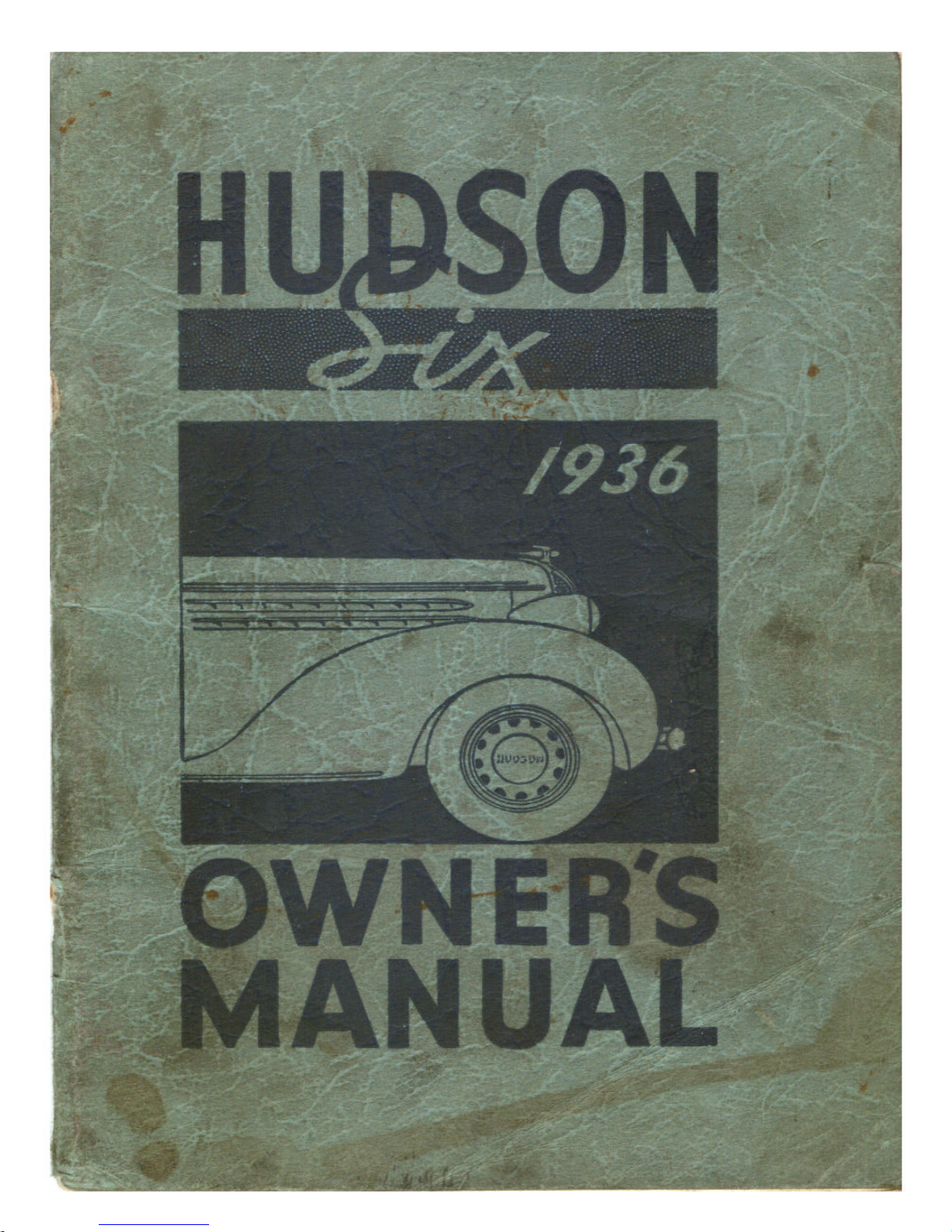
is available and the control button is located as shown in Figure I. When the
control button is pushed in, the automatic clutch control becomes operative. The
The transmission operation conforms to the standard shift. The clutch must be
disengaged (either by using the pedal or by removing the foot from the accelerator
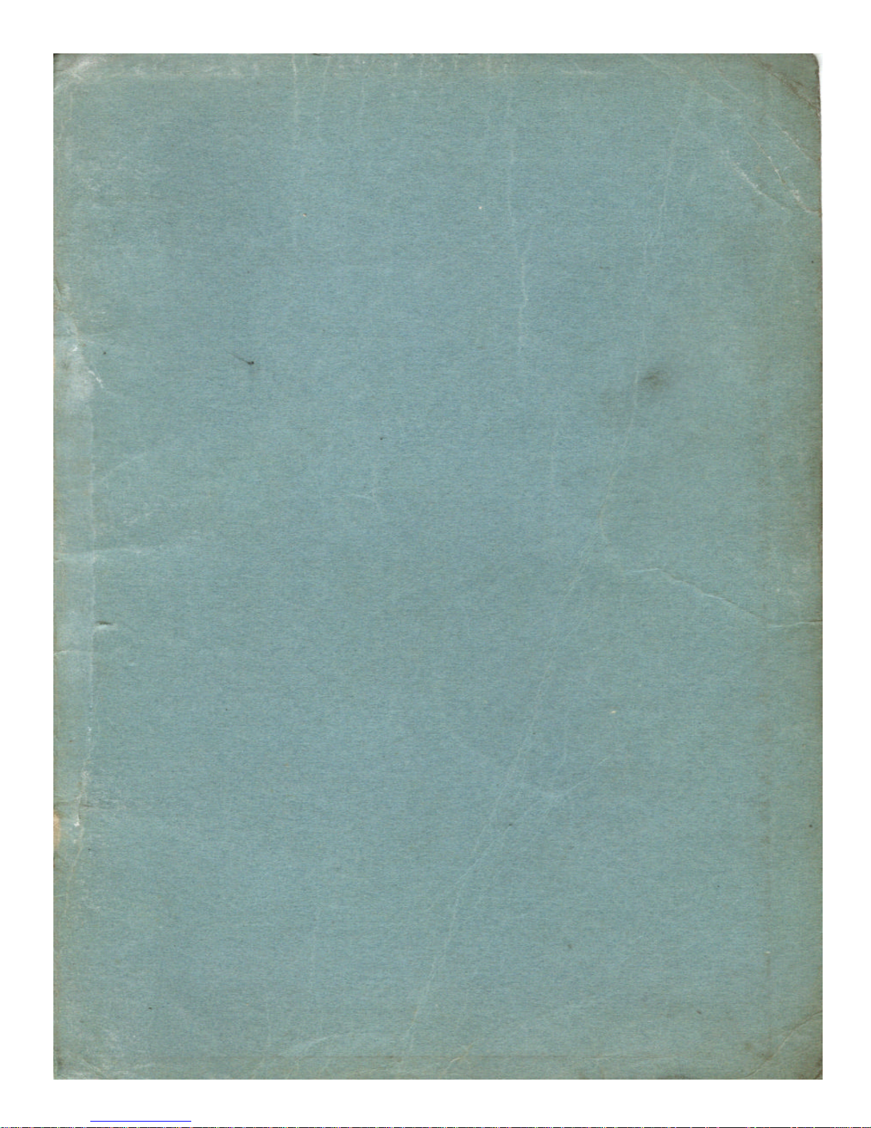
The "Electric Hand" transmission control, which is available as a factory-
installed option, has a small lever, Figure la, conveniently located just under the
rim of the steering wheel. This lever has five positions arranged in the form of the
letter 1-3 corresponding to the neutral, three forward and reverse positions of the
standard transmission shifting lever. This lever is easily moved to any of the
sary to lift up on the lever and at the same time push forward in order to get into
The control is electrical while the actual shifting is accomplished by vacuum
power from the engine intake manifold. The control is inter-connected with the
ignition switch and a circuit breaker on the clutch pedal, making it necessary to
have the ignition turned on and the clutch pedal depressed (clutch disengaged)
before the system is energized to accomplish a shift of gears. The starter is also
inter-connected with a circuit breaker on the clutch pedal, requiring the clutch to
be disengaged before the engine can be started. This is a safety feature, preventing
the car from being moved should the engine be started while the transmission is
Figure 1
OPERATION
on some of the details by reading the following paragraphs:
clutch is then disengaged simply by removing the foot from the accelerator pedal.
pedal when automatic clutch control is being used) before shifting gears.
forward gear positions to select the gear desired. As a safety feature, it is neces-
the reverse position.
in gear.
Page 12
To operate a car equipped with the
"Electric Hand" control: (1) see that
switch on selector housing is "on," (2)
depress the clutch pedal, (3) turn on the
ton. Now, with the engine running and
the clutch disengaged (if vacuum clutch
control is being used it is not necessary
to hold the clutch disengaged with the
foot after the engine is started; simply
take the foot off the accelerator pedal),
move the finger tip control lever to the
gear position desired and the shift will be
completed immediately. Allow the clutch
tor and the car will move normally for the gear selected. When it is desired to
make another shift simply depress the clutch pedal, move the finger tip control
With vacuum clutch the entire operation consists simply of removing the foot
from the accelerator pedal, moving the finger tip control lever to the desired gear,
then depressing the accelerator pedal to re-engage the clutch and feed the desired
A small toggle switch mounted on the selector housing can be used to make
the "Electric Hand" inoperative when the car is being serviced or to prevent
The need of a gear shift lever is eliminated on cars equipped with the "Electric
Hand" except should it be desired to shift the transmission when the engine is not
running. A hand gear shifting lever is provided with the tool equipment for this
purpose. By removing the cover in the floor mat, which exposes the top of the
transmission control, the shifting lever can be put in place and any desired shift
made after the clutch pedal has been depressed. The toggle switch on the selector
The brakes are operated on all four wheels by depressing the right foot pedal
while the two rear brakes are operated by pulling backward on the band lever
The engine speed is controlled by the foot accelerator. The engine idling speed
The lights on the car are operated by the main lighting switch, which is the knob
to the right of the center of the instrument panel, the instrument light switch
located under the instrument panel just to the left of the ignition lock, the front
compartment flood light switch located under the instrument panel to the right of
the ignition lock, the driving light control switch on the toe board to the left of the
clutch pedal, the dome lamp switch located on the right hand center pillar and the
10 HUDSON SIX
ignition switch, (4) press the starter but-
to engage while depressing the accelera-
lever to the gear desired and allow the clutch to re-engage.
amount of gasoline mixture to the carburetor.
tampering with the shifting mechanism.
switch housing should be turned off while the shifting lever is in place.
located under the instrument panel to the left of the steering column.
is automatically increased when the engine is cold to prevent stalling.
stop lamp switch.
Page 13

The main lighting switch has three positions. The central position is "off."
Turning the knob clockwise gives the driving lights, while anti-clockwise rotation
When the main lighting switch is in the driving position the driving light control
(foot) switch becomes effective. By pressing this control button and releasing it,
the headlamp beams may be deflected to the city driving position, immediately in
front of the car, Or to the country driving position, in which the light will be
projected a considerable distance ahead of the car. When the lights are in the
country driving position the small light at the bottom of the speedometer dial is
The instrument light switch is a gradual control giving any intensity of
The front compartment and dome lamp switches are of the conventional toggle
The stop lamp switch is located on the chassis frame and is connected to the
The starter is controlled by the push button to the left of the center of the
instrument panel. The ignition switch must he turned on, and on Electric Hand
equipped cars the clutch pedal must also be depressed when the starter button is
The carburetor is equipped with Climatic Control (self-controlled choke), which
gives correct fuel mixture for all starting and running conditions without any
The oil pressure signal is the red jewel located to the right of the center of the
instrument group. When the ignition switch is turned "on" this signal will be
lighted. If it remains lighted or flashes while the engine is running above idling
speed, the engine should be stopped and the oil level in the reservoir checked. If
The generator signal is the red jewel located to the left of the center of the
instrument group. When the ignition switch is turned "on" this signal will be
lighted and should stop glowing when the engine reaches a speed slightly above
normal idling. If the signal flashes when the car is being driven above twenty
miles per hour, it indicates that the battery is not being charged. Your electrical
The gasoline gauge, located at the left of the instrument group, indicates the
The water temperature indicator is located at the right side of the instrument group
Before attempting to start a cold engine, depress the accelerator pedal slowly
approximately 1/4 to half way and then release. This will allow the high idle speed
stop to come into position to prevent stalling during the warming-up period. Insert
the key in the ignition lock and turn to the right. Press the starter control button to
OWNER’S MANUAL 11
gives parking lights.
lighted. (See page 38 for Adjustment of Headlamps.)
illumination desired from off to full on by simply turning the knob.
type.
brake system so that the stop light is illuminated when the brakes are applied.
depressed.
manual control on the part of the operator.
necessary, check the oil lines. Do not run the engine until the trouble is corrected.
system should be checked by your Hudson Dealer.
quantity of gasoline in the tank.
and, like the gasoline gauge, is operative only when the ignition is turned on.
Starting the Engine
bring the starter into action and start the engine.
Page 14

If the engine is warm from previous running, the accelerator pedal should be
depressed approximately N to half way and held in that position during the
If the engine does not start after 15 to 20 seconds of cranking, release the starter
tioned, either before or during the starting operation, as this will cause the
accelerator pump to supply an excessive amount of gasoline and prevent correct
Should a flooded condition of the carburetor develop, either through operation
of the accelerator pedal or continuous cranking without the ignition turned on,
depress the accelerator pedal fully for further cranking of the engine. With the
accelerator pedal in this position, the choke is held open so that the excessive
Failure of the engine to start when the above procedure is followed can usually
be traced to improper engine adjustments or, in cold weather, a combination of
this and improper engine lubricant. The car should be taken to an Authorized
Hudson and Terraplane Dealer for adjustment or replacement of the oil with the
Your Hudson Six has been designed in accordance with the best practices
determined by years of experience and built under the most rigid standards of
precision. Before shipment from our factory, each mechanical unit was supplied
with the proper quantity of correct lubricant to give maximum protection to the
finely finished working parts. In fact, every precaution has been taken to put in
your hands an unexcelled mechanism, properly protected against premature wear.
Extreme care has been exercised in selecting and testing each lubricant used and
there is, therefore, no necessity of replacing any lubricants until the normal
In order to enjoy the maximum in life and trouble-free performance which has
been built into your Hudson Six, you should at all times give it the consideration
During the first one thousand miles you should be diligent in following accepted
practice, as described in later paragraphs, to permit proper break-in of the finely
finished working parts. Failure to follow this practice may result in damage to
bearing surfaces, cylinder walls or pistons, or abnormal increases in clearances,
Keep the radiator full of water at all times. Maintain the proper oil level in the
Do not accelerate fast during the break-in period, as this throws extreme loads
on the working parts. When increasing the speed of the car depress the accelerator
Do not apply the brakes harshly, as braking surfaces require the same care
12 HUDSON SIX
starting operation.
button and, after a few seconds, repeat the starting operation.
Do not work the accelerator pedal up and down, except as previously men-
starting.
amount of gasoline can he drawn through the engine readily.
correct grade for the local operating conditions.
Breaking-in Instructions
change mileage has been reached.
that any fine mechanism deserves.
which will shorten the life and impair the performance of the units.
oil reservoir, using the correct grade of good quality oil as prescribed on page 16.
pedal gradually. Use second gear under adverse driving conditions.
during the break-in period as do engine parts. Hard application of the brakes during
Page 15

OWNER’S MANUAL 13
The following recommendations should be ,followed as to speed during the first
one thousand miles of driving. These recommendations are maximum safe speeds
under favorable operating conditions. The speed of the car should be decreased
under unfavorable conditions, such as rough or rutted roads, or in climbing steep
Do not exceed 40 miles per hour in high gear or 20 miles per hour in second.
Your car is equipped with a governor installed and sealed at the factory to insure
While the governor is in place, the top speed and acceleration are restricted and
Your dealer will remove the governor and tune the engine for you when making
Maintain oil level in crankcase within "oil level range" on oil level gauge at all
Do not drive at a high rate of speed until the engine is thoroughly warmed up.
Cold oil is not able to flow freely into the small clearances between the working
TAINING GRAPHITE OR OIL CONCENTRATES EITHER IN THE ENGINE
OIL RESERVOIR OR BY ADDING TO THE GASOLINE DURING THE
BREAK-IN PERIOD. If such practices are followed by the owner, he should be
guided as to quantities by the recommendations of the manufacturer of the special
lubricant. Only light, finely refined oils should be added to the gasoline and not
Even where these special practices are followed, the recommendations of the
The unusual power, efficiency and economy of the Hudson Six engine are due
to a combination of such advanced designs as the chrome alloy cylinder block,
giving great strength and wearing qualities so as to almost eliminate wear on
cylinder walls and valve seats; silicon aluminum alloy pistons, cam ground and
fitted with a clearance of .002"; silicon chromium steel valves; down draft
carburetion—all built around a fully compensated crankshaft and lubricated by
the first few hundred miles may score the brake drums or gall the linings.
or continuous grades.
0-250 MILES
Do not accelerate rapidly. Use second gear on steep grades.
250-500 MILES
Do not exceed 50 miles per hour in high gear or 25 miles per hour in second.
500-1,000 MILES
During this period the speed should not exceed 60 miles per hour.
Important
it reaching you in good condition.
the air intake noise slightly increased.
the 500-mile inspection.
times. (See Figure 2.)
surfaces, so that damage may occur if this is not observed.
Special Lubricants
THERE IS NO NECESSITY OF USING SPECIAL LUBRICANTS CON-
to exceed one quart to a full tank of gasoline
foregoing paragraphs as to speeds and operation should be adhered to strictly.
ENGINE
the Hudson Duo-flo Automatic Lubricating System.
Page 16

The crankshaft is a heavy forging with integral compensating weights. Full
compensation and a torsional dampener mounted on the front insures free running
of the crankshaft under all operating conditions. The main bearings are removable
bronze backed, virgin babbitt and are fitted to .001" clearance and provided with
shims for adjustment. The working member of the dampener is rubber, fully
The connecting rods are steel forgings carrying spun virgin babbitt bearings in
the lower end fitted with a clearance of .001" and having shims .provided w for
adjustment. The upper end is fitted with a bronze bushing to which the piston pin
The pistons are of silicon aluminum alloy of new design. This alloy is hard,
lighter than aluminum and dissipates heat rapidly. The piston is "T" slotted to
compensate for expansion; cam ground to give full bearing on the cylinder wall;
and is fitted with two compression rings and one oil control ring above the piston
pin and one oil control ring below. With this arrangement all of the rings are
located somewhat lower down on the piston, with the result that cooler operating
conditions and better oil control are obtained. The piston is attached to the
connecting rod by a full floating pin, which is honed to give a perfect bearing in
the diamond bored piston bosses. The piston pin is a snug fit in the piston bosses
This piston design permits fitting to the cylinder with a clearance of .002". The
The camshaft is Electric Furnace Alloy with hardened bearing and cam surfaces.
End play is prevented by a spring and plunger pressing against the front end of the
The valves, which are silicon chromium steel, are operated by the cams through
adjustable tappets. The tappets should be adjusted while the engine is at normal
operating temperature. To adjust the tappets, remove the engine side cover plates
(right side of engine below intake manifold) and insert a feeler gauge between the
top of the tappet screw and bottom of the valve stem while the engine is running.
The valve tappets should be adjusted to a feeler gauge clearance of .006" on the
intake valves and .008" on the exhaust valves. The tappet screw locking nut should
be tightened securely after adjustment. The tappet clearance is important and
The valve timing is determined by the meshing of the crankshaft and camshaft
gears. The tooth of the crankshaft gear with the punch mark on the front face
The Hudson Duo-flo Automatic Lubrication System gives a positive flow of oil
to every working part of the engine from the moment of starting throughout the
period of operation. It also, through in-built features, conditions the oil so that all
oil supplied by the oscillating plunger pump is cooled and freed of solid matter and
14 HUDSON SIX
Crankshaft, Connecting Rods and Pistons
enclosed, requiring no adjustment.
is fitted with .0003" clearance.
when the piston is heated to 200° F.
pistons are removable from the top of the cylinder bore.
shaft.
Valve Tappet Adjustment
should be set accurately to the recommended dimensions.
Valve Timing
should mesh between the two punch marked teeth of the camshaft gear.
Lubrication System
diluents.
Page 17

There are only two moving parts in the entire system—the oscillating plunger
and the driveshaft of the pump, which is driven by gears direct from the camshaft.
There are no small drilled passages to clog or restrict free flow of oil when cold.
The oil pipes (3 in number) are all located outside the engine and can readily be
The crankcase ventilators mounted on the valve chamber covers are unusually
effective as diluents consist mainly of unburnt gasoline and water coming from
the cylinders and crankcase walls and cannot enter the oil reservoir but are
retained in the crankcase. The temperature here is near the boiling point of these
diluents and, with the agitation of the moving parts of the engine, they are readily
The flow of oil after returning to the
lates around passages adjacent to the cool
outside walls of the reservoir and is
cooled before passing through the filter,
which removes all solid matter before the
The filter surfaces are so placed that
they are flushed each time the crankcase
oil is drained and therefore require no
special cleaning nor do they have to be
Under operating conditions one quart
voir. If the oil reservoir is removed, one
quart of oil should be put into the upper
ervoir. The quantity of oil in the reservoir
Figure 2 can be determined by the bayonet gauge
When the oil level is down to the "low" mark, one inch from the bottom of the
gauge, three quarts of oil remain in the reservoir. Two additional quarts are
required to bring the level up to the mark at the top of the "oil level range". When
the reservoir only is drained by removal of the drain plug at the rear of the
reservoir, five quarts of oil should be used, filling through the opening in the left
The red jewel mounted to the right of the center of the instrument group should
be lighted when the ignition is turned on but go out when the engine is running at
slightly more than idling speed. Flashing of the light at idling speed indicates
OWNER’S MANUAL 15
removed should there be any necessity to do so.
Crankcase Ventilation and Oil Conditioning
vaporized and removed by the slight suction maintained on the ventilator tubes.
crankcase is controlled so that it circu-
oil is recirculated by the pump.
replaced.
Oil Capacity
of oil is retained in the crankcase in addition to the five quarts of oil in the reser-
crankcase tray and five quarts in the res-
attached to the filler cover. (See Figure 2.)
side of the crankcase. (See Figure 2.)
Page 18

proper operation. Should the light come on when the engine is running above
idling speed it indicates interruption of the oil supply and the engine should be
The viscosity of a lubricant is simply a measure of its body or fluidity. The
S.A.E. viscosity numbers constitute a classification of lubricants in terms of
THE REFINER OR MARKETER SUPPLYING THE OIL IS RESPONSIBLE
FOR THE QUALITY OF ITS PRODUCT. THEIR REPUTATION IS THE CAR
nies and no difficulty should be experienced in obtaining the proper grade of
The grade of oil best suited for each range in temperature is shown by the
accompanying table. The car owner should always select an oil having the
During the winter months the owner's selection of crankcase oil should be based
primarily on easy starting characteristics. The viscosity of 10 W and 20 W oils is
such as to permit easy starting down to the minimum temperature for wbich they
Oils carrying the S.A.E. specification and not a (winter) specification are
istics of such oils will vary depending upon the type of crude and the refining
specification for winter starting qualities, the specification on the container is the
The oil level should be maintained within the "oil level range" on the oil level
gauge at all times. Drain oil after first 500 miles of operation and at 2,000 mile
The distributor is mounted on the right side of the crankcase and driven by gears
from the camshaft. A single breaker arm is operated by a six-lobe cam. Automatic
16 HUDSON SIX
stopped until the cause is corrected.
Lubricants
viscosity, or fluidity, but without reference to any other characteristics or properties.
OWNER'S BEST INDICATION OF QUALITY.
The S.A.E. viscosity numbers have been adopted by practically all oil compa-
lubricant to meet seasonal requirements.
recommended temperature range agreeing with the lowest atmospheric temperature likely to be encountered before the next oil change.
are recommended.
selected only on their viscosity at higher temperatures and the starting character-
process.
Although there are oils carrying the S.A.E. specification which also meet the
car owner's only definite assurance as to the starting qualities of the oil.
Minimum Atmospheric
Temperature Expected Oil Specification
40° Fahrenheit S. A. E. 30
0° Fahrenheit 20 W.
-15° Fahrenbeit 10 W.
Below -15° Fahrenheit 10 W. Plus 10% Kerosene
intervals thereafter. Refill with five quarts of oil of proper specification.
Ignition System
advance is incorporated so that the correct timing is given at all speeds
Page 19

The oil cup (F), Figure 3, should be
filled with oil every 2,000 miles. At the
same time remove the distributor cap
(not shown) and rotor arm (D), placing a
few drops of oil on the top of the shaft,
one drop of oil on the breaker arm pivot
(B), and apply a light coating of vaseline
The breaker points should be adjusted
to .020" maximum opening. The points
should be clean and set squarely on each
other. If the points become pitted it is
necessary to remove them and grind
smooth or replace with new ones. The grinding should be done in a special
machine to insure proper seating. This operation should be done by an Authorized
Filing or honing of the points will remove oxidization from the points but, due
to the hardness of the tungsten alloy used, this method is not practical for
Loosen the distributor clamp screw (C), Figure 3, and turn the distributor until
the fiber block (A) of the breaker arm is on the highest point of the cam. Measure
the gap between the breaker points with
actly .020". If adjustment of the gap is
required, loosen lock nut (H) and turn
adjusting screw (J) until the proper gap is
The ignition timing is determined by
tributor breaker points begin to open. In
general, the points should begin to open
tion in the cylinder. This position of the
piston is referred to as upper dead center
OWNER’S MANUAL 17
Figure 3
Figure 4
Lubrication
on the cam block (A).
Breaker Points
Hudson and Terraplane Service Station.
removing deep pits.
Breaker Point Adjustment
a feeler gauge. This gap should be ex-
obtained. Tighten lock nut (H) and recheck the gap.
Ignition Timing
the position of the piston when the dis-
when the piston reaches its highest posi-
and is indicated by U. D. C. Marks are placed
Page 20

18 HUDSON SIX
Since the piston in a four-stroke cycle engine may be completing the exhaust
stroke or completing the compression stroke and ready for the power stroke when
it reaches U. D. C., it is necessary to determine the stroke as well as the piston
To determine this, remove the spark plug from number one (front) cylinder.
Place the finger over the spark plug hole and crank the engine slowly, using the
hand crank. Air pressure against the finger indicates that the piston is coming up
on the compression stroke. After this is felt, continue cranking the engine slowly
until the mark "U. D. C. 1 and 6" is directly in line with the pointer on timing
inspection hole in the rear support plate of the motor as indicated at (A), Figure 4.
Turn the distributor housing clockwise to the limit of the slot in the clamping
plate (K), Figure 3. Remove the central cable from the distributor cap and place
the bare end about IA" from the intake manifold. With the ignition turned on and
the U. D. C. 1-6 mark on the flywheel in line with the pointer on the inspection
hole (Figure 4), turn the distributor body counterclockwise slowly just until a
spark jumps from the high tension wire to the intake manifold. Tighten clamp
When the distributor cap is put in place, the metal strip on the rotor arm should
be directly under the terminal to which number one spark plug wire is attached.
The other cables should be in the cap terminals in the order 1-5-3-6-2-4, following
in a clockwise direction. The cable in the center terminal of the distributor cap
The foregoing operations give dead center timing. This, however, due to
variations in fuel characteristics (octane rating) is only approximately correct. To
get the correct setting the car should be driven until the engine has reached its
normal operating temperature. Allow the car to slow down to 7 miles per hour in
high gear on a level, hard-surfaced road, then depress the accelerator rapidly to its
limit of travel. As the car accelerates from 10 to 15 miles per hour a slight spark
knock should develop. If a knock is not heard, loosen distributor clamp screw (C),
Figure 3, and turn the distributor counterclockwise one graduation of the clamping
plate (K), Figure 3, and repeat the acceleration test. Repeat this operation until the
knock is heard. The higher the octane rating of the gasoline being used, the greater
the advance required to get maximum performance and fuel economy. However,
the timing should not be set more than 3/4" ahead of the U. D. C. mark on the
The carburetor is of the down draft type, incorporating Climatic Control
(self-controlled choke), automatic heat control, and an accelerating pump. The
only manual control for the operator is the accelerator pedal controlling the
on the flywheel to indicate when this position of the piston has been reached.
position.
the piston is then at U. D. C. and ready to move downward on the power stroke.
Setting Ignition Timing
screw (C), replace central cable in distributor cap and clamp cap on distributor.
should go to the central (high tension) terminal of the ignition coil.
Fuel Compensation
flywheel.
Carburetor and Fuel System
throttle opening for regulating the speed of the engine.
Page 21

The choke valve, the mechanism for
which is contained in the insulated
housing (4), Figure 5, is fully closed
when the engine is cold at average air
temperatures (75° Fahrenheit). Hot air
drawn off the exhaust manifold through
the stove (B) and tube (C) enters the
tioning of the choke for all starting and
When the choke is closed the bar (D)
is dropped behind the throttle stop screw
(E) to increase the idling speed during
not drop into position until the throttle has
been opened. The heat control valve (F) is
automatic in operation, supplying the
correct amount of heat to the intake manifold
The air cleaner should be removed every 2,000 miles, the wing nut (G)
unscrewed and the cover and pad removed. Wash filter in gasoline and re-oil by
On cars equipped with the heavy duty oil bath cleaner (special equipment),
remove wing nut and cover and withdraw filter assembly. Remove old oil from
body and wash all parts in gasoline. Fill body with S. A. E. 30 engine oil to level
of ring pressed in body. Service filter unit as in standard cleaner and reassemble.
This should be done at least every 2,000 miles or oftener if extreme dust
The cap screw holding the cover in place should be removed, permitting the
removal of the cover and filter screen for cleaning every 2,000 miles. At the
same time the drain plug, located just below the pump inlet, should be removed
and the sediment chamber cleaned. This should be done particularly in cold
Do not attempt to adjust the carburetor alone. Perform all of the following
distributor wires are pressed down in
OWNER’S MANUAL 19
Figure 5
Carburetor Choke
control housing, giving accurate posi-
operating conditions.
the warm-up period. This, however, can-
under all operating temperatures.
Air Cleaner
dipping in S. A. E. 50 engine oil. Drain excess oil and replace pad and cover.
conditions are encountered.
Fuel Pump
weather to remove any water which may have accumulated.
Engine Tuning
operations in the order given
1. Clean spark plugs and adjust gaps to .025".
2. Clean distributor breaker points and adjust to .020" maximum opening as described under
Breaker Points. (Page 17.)
3. Check battery and ignition wiring, being sure all
their sockets and insulation is in good condition and battery terminals clean.
Page 22

10. Road test for final ignition timing, as described under Fuel Compensation (page 18).
the car should be taken to an Authorized Hudson and Terraplane Dealer for mechanical
The starting motor is controlled by a push button on the instrument panel through a
It is necessary to disengage the clutch on Electric Hand equipped cars in addition to
turning on the ignition and pressing the starter button to engage the starter. The switch
can be operated manually by unscrewing the cap on the rear of the switch and pushing
the plunger in. The drive to the gear on the engine flywheel is through a Bendix drive
The front and rear bearings of the starting motor should be lubricated at (B and D),
The threads of the Bendix screw shaft (C), Figure 4, should be cleaned occasionally with
The generator is of the ventilated type, allowing a greater output than is practical with
the non-ventilated type. The maximum output is controlled by a third brush and should
be set at 22 amperes. This adjustment requires the use of an accurate ammeter and
A generator output regulator is mounted on the engine side of the body dash and
reduces the output from 22 to 10 amperes when the battery is fully charged, reverting to
the higher rate should the battery become partially discharged due to frequent starting or
The generator field circuit fuse is contained in the knurled cup extending from the top
of the regulator. If the generator fails to charge, check for a burnt- out fuse. Replacement
20 HUDSON SIX
4. Set ignition timing as described on page 18.
5. Turn carburetor idling screw (H), Figure 5, into its seat and back out exactly one
turn.
6. Start engine.
7. When engine has reached normal operating temperature, adjust intake valve
tappet clearance to .006" and exhaust tappet clearance to .008".
8. Set carburetor throttle stop screw (E), Figure 5, so that engine idles at a speed
equal to a car speed of 7 m. p. h. in high gear.
9. Adjust carburetor idling screw (H) for smooth engine idling. The final adjustment
should be from ½ to 1 turn of the screw from its full in position.
If the above operations, properly performed, do not give normal engine performance,
inspection.
Starting Motor
solenoid switch mounted on top of the starting motor.
which is brought into engagement by the rotation of the starting motor.
Figure 4, with a few drops of light oil every 1,000 miles.
a brush and kerosene to remove gum and dirt.
Generator
voltmeter and should be made by an Authorized Hudson and Terraplane Service Station.
continuous use of lights, radio, etc. This regulation is permanently built into the regulator and no adjustment of this unit is necessary.
should be made only with a 7½-ampere, 25-volt fuse.
Page 23

A few drops of light oil should he supplied to cups (A), Figure 6, every 1,000
The generator is driven by the "V" type belt, which also drives the fan and water
pump. This belt must be kept sufficiently tight to, prevent slippage on the pulleys.
When properly adjusted the belt will have from ¾" to 1¼" of slack at a point
midway between the fan pulley and generator pulley as shown at (E), Figure 6.
This adjustment provides sufficient tightness to prevent slippage without causing
To tighten belt tension loosen nut (B) and swing generator away from the engine
The water pump is of the vane type located on the front of the cylinder block
and driven by the "V" belt, which also drives the generator. The adjustment of the
The packing gland is of the permanent type, built entirely inside of the pump
The pump should be lubricated every 1,000 miles through the pressure fitting
OWNER’S MANUAL 21
Figure 6
miles—do not over-lubricate.
Fan Belt
undue wear of the fan and generator bearings.
until correct position is obtained. Tighten nut (B).
Cooling System
Water Pump
belt is covered in the preceding paragraph.
and requires no adjustment.
(C), Figure 6, with a high-grade aluminum soap grease.
Page 24

22 HUDSON SIX
The cooling system is of the pressure pump circulation type, with thermostatic
heat control. This provides positive circulation, combined with a short warm-up
period, in spite of a total cooling capacity sufficient to give proper cooling under
When the water in the cooling system is cold, the thermostat which is located
in the cylinder head outlet causes the water to flow through a by-pass directly to
the pump inlet. During the warming-up period, therefore, the water in the cylinder
jacket alone is circulated, while the water in the radiator is completely cut off from
When the temperature of the water in the jackets has reached 140° Fahrenheit,
the thermostat begins to open the passage into the radiator, and at approximately
To completely drain the cooling system open the petcock at the bottom of the
radiator (left side under hood) and also remove the pipe plug from the cylinder
In order to get the maximum efficiency from the cooling system, it must be kept
clean. There is a tendency toward corrosion of parts due to electrolytic action of
water containing minerals and also deposits of minerals when the water is heated.
Both the corrosive scale and the mineral deposits tend to coat the cooling surfaces,
Unless special steps are taken to prevent these deposits, the cooling system
should be cleaned twice a year. This cleaning is most effective when reverse
flushing is used to remove deposits after they have been loosened by the use of a
ated by compressed air, you should have this done by an Authorized Hudson and
The cleaning solution recommended is Hudson Radiator Cleaner. Before using
this solution, run the engine a few minutes to circulate the water and stir - up loose
sediment. Stop the engine and open radiator petcock and drain all water from the
Dissolve the contents of a container of Hudson Radiator Cleaner in a bucket of
hot water (be sure the material is completely dissolved). Pour solution into
With the radiator covered and filler cap tight, run the engine for about twenty
It is important that all traces of the cleaning solution be removed, as they have
Cooling System Operation
the most unfavorable operating conditions.
the remainder of the cooling system.
160° the by-pass is closed so that all the circulation is through the radiator.
Draining Cooling System
block (left side to rear of side cover plate).
Care of the Cooling System
reducing radiation, and in time will clog the radiator passages.
good cleaning solution. Since reverse flushing requires special equipment oper-
Terraplane Dealer.
system.
radiator, then fill the radiator almost full of water.
minutes but avoid boiling. Stop the engine and completely drain system.
Reverse flushing will remove all of the sediment the solution has loosened.
a detrimental effect if left in the system.
Page 25

After thoroughly flushing the cooling system, the addition of Hudson Rust
and Corrosion Inhibitor to the water will neutralize the action of any cleaning
compound which may not have drained out. It will also prevent corrosion of
the cast iron, aluminum and other metals in the cooling system. The practice
of using the Inhibitor in the cooling water is particularly advantageous for
Before putting any anti-freeze in the cooling system, it should be thoroughly
lytic action should be avoided. They will cause serious corrosion of aluminum
alloy as well as the solder joints of the radiator. Also avoid the use of solutions
containing glucose or honey, as they will tend to clog the system; and of
The following table gives the quantities of the recommended solutions re-,
OWNER’S MANUAL 23
engines equipped with aluminum cylinder heads.
Hudson Radiator Cleaner and Inhibitor can be obtained from any Authorized Hudson and Terraplane Dealer.
Anti-Freeze
cleaned and all hose connections and gaskets checked for leaks.
The types of anti-freeze recommended are: Alcohol, Glycerine and solu-
tions of Ethylene Glycol marketed under various trade names.
Solutions containing calcium salts or other ingredients which promote electro-
kerosene or fuel oil which, when hot, liberate inflammable vapors.
quired for protection against freezing at various temperatures:
Temperture
Fahrenheit
+20°
+10°
0°
-10º
-20°
-30°
Alcohol
Quarts
2½
3¾
5
5¾
6½
8
Radiator Glycerine
(C.P.A. or Equivalent)
Quarts
5¾
7¼
9
10½
12
13—Full Strength
Ethylene Glycol
(Prestone or Equivalent)
Quarts
2½
3½
4½
5
5¾
6½
Page 26

24 HUDSON SIX
Page 27

The clutch is of the single plate type, having a plate with frictional surfaces
which is driven by friction from the rear face of the steel flywheel and the forward
face of the drop forged steel pressure plate. The frictional facing in Hudson
cated to give a maximum degree of
Due to the film of lubricant on the
frictional surfaces, burning is prevented
face is always protected and maintained
sonite Clutch Compound, so that even
after thousands of miles of usage there
The throwout bearing is a heavy duty
cation through a pressure fitting located
ing. This should be lubricated with one
ounce of aluminum soap grease every one
The Hudsonite Clutch Compound is permanently sealed into the clutch housing
to prevent loss. It should be drained and
replaced every five to fifteen thousand
To insert the Hudsonite, turn the engine
until the drain plug (A), Figure 7, in the
front face of the flywheel is visible
through the timing inspection hole in the
left side of the rear engine plate. Remove
the plug (A) and turn the engine slowly
until the star stamped in the front of the
flywheel is visible through the inspection
hole. Allow a minute in this position to
permit the clutch housing to drain, then
turn the engine until the filler hole again
third pint of Hudsonite. Replace the plug
able through all Hudson and Terraplane
OWNER’S MANUAL 25
Figure 7
CLUTCH
clutches is pliable formed cork and lubri-
smoothness in engagement.
and wear is negligible. The frictional sur-
in proper condition by the bath of Hud-
will be no material change in the engaging characteristics.
Lubrication
ball bearing provided with positive lubri-
on the right side of the clutch bell hous-
thousand miles.
miles.
appears in the timing hole and insert one-
and tighten securely. Hudsonite is avail-
Distributors and Dealers.
Page 28

26 HUDSON SIX
The clutch is self-adjusting; however, it is necessary to adjust the clutch pedal
rod to prevent the pedal from "riding" the floor board. To adjust, loosen lock nut
(A), Figure 8, remove clevis pin (C) and turn yoke (B) to shorten or lengthen the
rod, as necessary, so that the pedal shank can be held in a position one and
one-half inches from the floor board when the clutch is engaged. Replace the
clevis pin (C) and cotter pin. Tighten lock nut (A). The pedal clearance should be
On cars equipped with Automatic Clutch Control, pull backward on the power
unit rod—on left side of engine while the accelerator pedal is depressed. When the
ance between the back of the slot in the rod yoke and the clevis pin which attaches
The transmission is of the quick synchronizing type incorporating helical gears
to give a silent second speed. Unusual silence is obtained in all forward speeds by
throwing the reverse idlers out of mesh so that they do not revolve except when
num in gears which are heat treated for strength and case hardened to resist wear,
long life is assured. The use of these special alloys also makes extremely heavy
The main drive gear and main shaft are supported by two heavy duty, annular
thrust ball bearings, one annular ball bearing and thirty needle bearing rollers. The
end thrust between these parts is taken by seven ball bearings running in races
The countershaft is carried on steel-
The lubricant used must be able to
withstand the pressure developed between
the gear teeth and also flow freely into the
small clearances of the hearings. These
qualities can be obtained in S. A. E 90 E.P.
transmission gear oil for summer and S. A.
E 80 E.P. (zero pour test) transmission
gear oil in winter. When hard shifting is
encountered during cold weather, three
ounces of kerosene should be added to the
The transmission should be filled with
lubricant to the level of the filler plug (A),
Figure 9, at all times. Drain the lubricant
Figure 9
Clutch Pedal Adjustment
checked frequently, as a lack of clearance will cause clutch slippage.
rod is in its extreme rearward position there should be approximately 7/8" clear-
it to the operating lever.
TRANSMISSION
in actual use. Through the use of steel alloyed with nickel, chrome and molybde-
parts unnecessary, contributing greatly to ease and rapidity of shifting.
machined in the ends of the shafts
backed babbitt bearings.
Lubrication
lubricant.
with change of season
Page 29

OWNER’S MANUAL 27
Transmission
Page 30

28 HUDSON SIX
Rear Axle
Page 31

by removing plug (B) and replacing with three pounds (or pints) of fresh oil of
The front and rear universal joints are fitted with needle roller bearings at the
trunnions for the purpose of minimizing friction and maintenance attention. Oil
reservoirs provided at each bearing are filled with lubricant at the time of
At 20,000-mile intervals both universal joints should be disassembled, cleaned,
Every 2,000 miles, the splined hub of the front universal joint should be
The rear axle is of the semi-floating type carried in a one-piece, welded, banjo
type housing. This gives a rugged assembly, with all parts readily accessible, as
ential assembly; also the differential and gear set assembly can be removed as a
unit, after the axle shafts have been removed, by simply disconnecting the rear
The helical bevel drive gear and pinion are made of nickel molybdenum electric
furnace steel, heat treated for strength and case hardened to resist wear. The drive
pinion, differential and axle shafts are carried by six heavy duty, taper roller
Exceptional lubrication has been provided to the driving pinion bearings by
arranging a large passage to carry oil thrown from the ring gear to a point in the
housing between the front and rear pinion bearings. This oil flows through the
bearings and returns to the axle housing. Oil leakage at the front of the pinion is
draulic leather oil seal. Similar seals
To adjust rear wheel bearings, jack
up rear axle and remove both rear
wheels and hubs. Remove the four
nuts from bearing cap (A), Figure 10,
and push the bolts out of the backing
brake operating link. By removing
shims (B) under the cap the end play
of the axle shaft is decreased. Total
play between axle shafts should be
tible by pulling shaft in and out with
OWNER’S MANUAL 29
the proper specifications.
UNIVERSAL JOINTS
assembly and supply the necessary lubrication for long periods of operation.
repacked with good viscous chassis lubricant and reassembled.
lubricated by removing the pipe plug and introducing viscous chassis lubricant.
REAR AXLE
the axle shafts and wheel bearings can be removed without disturbing the differ-
universal joint flange and removing the ten carrier bolt nuts.
bearings.
Figure 10
guarded against by the use of a hy-
are located in the wheel bearing caps.
Adjustment
plate to permit removal of the bearing cap wlthout disturbing the hand-
from .005" to .010", which is percep-
the hand.
Page 32

30 HUDSON SIX
Page 33

OWNER’S MANUAL 31
It is necessary that the thickness of shims at each rear wheel be approximately
the same, so when adjusting remove a thin shim from each side and repeat, if
necessary, until only a slight amount of play is evident. Be sure the axle shafts
Under no condition should a knockout type puller be used to remove a wheel
An oil must be used that will withstand the
pressures developed between the gear teeth
and also flow freely to enter the smaller
sages to the pinion bearings. These qualities
can be obtained in a heavy-bodied gear oil of
S. A. E. 110 E. P. viscosity for summer and
The oil should always be kept to the level
of the filler plug (A), Figure 11. Drain the oil
and replace with three pounds (or pints) of
The wheel bearings are lubricated with
wheel bearing grease. The bearings should each be packed with one and one-half
ounces of grease every 5,000 miles. In order to insert this grease the wheels and
The front axle is of the Elliott type, see Figure 12, the center section being a
heavy drop forging of high quality carbon steel. The steering spindles, which are
drop-forged molybdenum alloy steel, are attached to the axle center with alloy
steel spindle pins mounted in hardened steel bushings with ball bearings to carry
Each wheel is mounted on two taper roller bearings. The tie rod ends are of the
The axle is attached to the chassis frame by two torque arms (A) which insure
accurate positioning of the axle, and relieves the front springs of all loads other
than that of supporting the weight of the car. The torque arms are attached to the
The springs are mounted on bearings (B) which permit free turning on the axle
center and each end of the spring is attached to the frame through shackles (C).
All points requiring lubrication are equipped with pressure fittings except the
turn freely before building up.
Caution
hub or the end of the axle shaft struck a heavy blow.
Lubrication
clearances and circulate through the pas-
S. A. E. 90 E. P. for winter.
Figure 11
fresh oil with change of season.
wheel bearing caps must be removed, as described under wheel bearing adjustment.
FRONT AXLE AND SPRING SUSPENSION
the thrust on the end of the pin.
ball bearing type for frictionless control.
frame through large rubber bushings to absorb road shock.
This permits unrestricted spring action for a smoother ride under all road conditions.
wheel bearings.
Page 34

32 HUDSON SIX
After jacking up the front axle and removing the hub cap, withdraw cotter key
holding nut (A), Figure 13. Turn nut (A) to the right until a slight drag is felt when
turning the wheel slightly by hand. Then
loosen the nut just sufficiently to permit
The front wheels should be adjusted
with zero to 1/8" toe-in measured 10"
from the ground. This adjustment is
made by loosening the clamp bolts in the
tie rod ends, Figure 12, and turning the
tie rod in a clockwise direction, as
viewed from the right, to increase toe-in
and in the reverse direction to reduce
A special tool is required to make this
ment is important for correct steering and to prevent excessive tire wear. Have
The caster (backward tilt of the axle) should be from 2° to 3° and should he
By loosening nut (D), Figure 14,
removing capscrew (E) and replacing
shim (F) with a thicker shim caster is
decreased. Replacing shim (F) with a
The camber (outward tilt of front
Should any front axle parts become
bent, through accident, to such extent that
ing, they should be replaced with new
ones. Heating will destroy the original
heat treatment of the parts and may result
Figure 14
Bearing Adjustment
the wheel to turn freely. Insert cotter key.
Front Wheel Alignment
toe-in.
Figure 13
measurement accurately. This adjustm-
your Authorized Hudson and Terraplane Dealer check this alignment frequently.
Caster
equal within ½° at both front wheels.
thinner shim increases caster.
Camber
wheels) should he from 1° to 1½°.
they cannot be straightened without heat-
in sagging or even breakage.
Page 35

The front wheel bearings should be lubricated every 5,000 miles with a good
grade of wheel bearing grease. Remove hub and wash bearings and inside of hub
with kerosene and pack each bearing and hub with 3 ounces of wheel bearing
The tie rod ends are lubricated and sealed when assembled and require no
Lubrication of parts equipped with pressure fittings is covered on the lubrication
OWNER’S MANUAL 33
Lubrication
grease (see page 32 for adjusting wheel bearings).
further lubrication.
chart (inside back cover).
Page 36

34 HUDSON SIX
The steering gear on the Hudson Six is of the variable pitch worm and sector
The maximum ratio of 17 to 1 is obtained in the straight ahead position to give
maximum ease of steering. The ratio is reduced as the gear is turned either to the
The worms are cut in a manner which gives a minimum clearance, with the
sector in the straight ahead position and increased clearance on turns. This gives
maximum control and assures freedom from binding, even after extensive use,
which on conventional gears makes it impossible to get proper clearance without
binding on extreme turns due to maximum wear coming in the straight ahead
position.
The main or worm shaft is carried on two taper roller bearings, which are
maintained in proper adjustment by a
shim pack which is properly selected
The end play in the cross shaft is
adjusted by a screw extending through
ing the end play is reduced. The screw
should be tightened, then backed off just
enough to prevent binding, and the lock
The mesh between the worm and
sector of the gear is adjusted by moving
the housing cover. To adjust, loosen the
four (one not shown) housing cover stud
nuts (B), Figure 15, one-quarter turn.
With front wheels jacked up and in the
ual stages, noting the effect by working the steering gear arm. When play has
been reduced sufflciently, tighten nuts (B), drawing up the one on eccentric (C)
first. Before lowering front wheels, turn steering gear from extreme right to
To raise or lower steering wheel to suit the requirements of the driver, loosen
frame bracket stud nuts (D), as well as steering column bracket nuts under the
instrument panel. Set the wheel in the desired position and tighten column bracket
The housing should be filled at all times with a good grade of S. A. E. 110 E.P.
gear oil in summer and S.A.E. 90 E.P. gear oil in winter. The lubricant can be
STEERING GEAR
type.
right or left to give quick action for sharp turns.
Adjustment
when the gear is built.
the right side of the steering gear housing. By turning this screw into the hous-
nut tightened.
Figure 15
straight ahead position, turn the eccentric (C) in a clockwise direction in grad-
extreme left to be sure no binding occurs.
nuts. Turn steering wheel to align gear on frame and tighten frame bracket nuts.
Lubrication
Page 37

OWNER’S MANUAL 35
Figure 16
Page 38

36 HUDSON SIX
injected after removing filler plug (E), Figure 15, and should he done with change
The Hudson brakes are hydraulically operated with supplementary mechanical
actuation of the rear brake shoes both from the foot pedal and the hand brake
The heart of the hydraulic system is
the master cylinder, Figure 17, which
has an integral reservoir from which
The master cylinder is mounted on
the chassis frame side member and is
accessible by lifting the left side of the
The reservoir should be kept at least
Figure 17 the filler plug (1), Figure 16, wipe all parts free of dirt and take extreme
The reservoir should be filled with Hudson fluid. The use of other than genuine
Hudson fluid or the introduction of oil with a mineral base into the system will
from the brake pedal (4). (Figure 16.) In order to insure full return of the piston
when the brake is released there must be 1/4" to 3/8" free pedal pad movement
before the piston starts to move as the pedal is depressed. This free movement is
adjusted by loosening lock nut (5), removing clevis pin (6) and turning the yoke
(7). After proper free pedal movement is obtained, replace the clevis pin (6) and
tighten lock nut (5). This adjustment is important as failure of the piston to return
An occasional filling of the reservoir should he the only attention required to
the hydraulic system unless the reservoir is permitted to run dry, a main line is
disconnected or a wheel cylinder is disconnected for service operations. If the
reservoir runs dry or a main pipe line is disconnected it is necessary to bleed the
air out of the lines at all wheel cylinders. If a wheel cylinder is disconnected it is
of season.
BRAKES
control. (Figure 16.)
additional fluid is supplied to the system as necessary.
hood.
half full at all times. Before removing
care to prevent dirt getting into the cylinder.
cause the rubber parts to swell and become inoperative.
The piston in the master cylinder is operated through the lever (2) and rod (3)
to the end of the cylinder will cause the brakes to drag.
necessary to bleed only at that particular cylinder.
The bleeding operation is performed as follows:
Figure 18
Page 39

OWNER’S MANUAL 37
(1) Remove the screw (D), Figure 19, and screw the end of the bleeder tube
(A), Figure 18, in its place and allow end of tube to hang in a jar partially filled
(2) Slip the bleeder wrench (B), Figure 18, over the tube until it engages on the
(4) Push the brake pedal down and allow it to return slowly. This will force
liquid and air out the bleeder tube. Continue this operation until air bubbles cease
(5) Close the bleeder valve (E), remove the bleeder hose and wrench, replace
CAUTION—Do not use a substitute for Genuine Hudson Hydraulic brake fluid.
Use Genuine Hudson Hydraulic brake fluid Number 5 except when continuous
sub-zero temperatures are encountered. Hudson Number 1 fluid is recommended
for use at extreme low temperatures.
With equalizer bar against stop loosen lock nut (8) and turn adjusting nut (9)
until rear face is 1-29/64" from front end of push rod (10) as shown in Figure 16.
Tighten lock nut. This adjustment is important to obtain proper mechanical
There are only two points of adjustment in the braking system to compensate
for brake lining wear. The Eccentric Adjustment (B), Figure 19, centralizes the
brake shoes in the drum. The Adjusting Screw, accessible by removing cover (C),
(2) Disconnect rear wheel cables from
(3) After removing adjusting hole
covers (C), Figure 19, and gauge hole
covers in brake drums, AT EACH
WHEEL: Loosen eccentric lock nut (A),
Figure 19, and insert .010" feeler gauge
between the lining of secondary (eccentric
controlled) shoe and brake drum. Turn the
he direction of forward wheel revolution
until .010" feeler is just snug at anchor and
adjusting ends of secondary shoe. Tighten
with liquid.
hexagonal section of the bleeder valve (E), Figure 19.
(3) Open the bleeder valve ¾ turn.
to be emitted from the bleeder tube.
the screw (D), Figure 19.
(6) Refill reservoir.
Substitutes are not suitable for this system.
Do not use fluid that has been drained out of the system. Always replace with new.
Adjustment of Pedal Push Rod
follow-up to the hydraulic operation of the rear brakes.
Brake Shoe Adjustment
Figure 19, takes up the clearances between the lining surfaces and the brake
drums.
Adjustment for Wear Only
(1) Jack up all wheels clear of the floor.
equalizer bar.
eccentric adjustment in
Figure 19
eccentric lock nut.
Page 40

38 HUDSON SIX
The clearance at both ends of the secondary shoe should not vary more than
.003". Should the variation be greater than this it will be necessary to relocate the
anchor pin. This work should be done by an authorized Hudson and Terraplane
Service Station. (In case of clearance variation it is desirable that clearance at the
(4) Spread the brake shoes by means of a screw driver inserted through the hole
(C) engaging the notched adjusting screw wheel until the shoes are expanded
(6) Pull rear brake cables tight and adjust ends so clevis pins just enter holes in
plate. The rear face of the equalizer plate must be parallel to the face of the stop
(8) Release adjusting screw at each wheel until the brakes are just free of drag
(9) Lower car and test for balance on brake testing machine or road. Always
loosen adjusting screw on tight brakes rather than tighten adjusting screw on
loose brakes to get balance. This is to safeguard against one or more dragging
The spring leaves are lubricated with a thin coating of graphite grease and
sating shock absorbers. By using a large quantity of fluid working under low
pressure, accurate control is obtained and there is no variation due to changes in
The large reserve of fluid, the low operating pressure and the double seal
practically eliminate the loss of fluid. The fluid should, however, be maintained
at the proper level and it is recommended that this be checked by an Authorized
The headlamps are designed to give maximum safe illumination under all
driving conditions. The only adjustment necessary to obtain the results which
should he expected is the proper aiming of the headlamps. The right and left
lenses are interchangeable and can he used satisfactorily on either side. The lamps
are fitted with standard 1-candle power bulbs for the parking position and
pre-focused bulbs having a flanged mounting and employing a 32-candle power
filament for city driving and passing, and a 32-candle power filament for country
driving. When the main lighting switch is in the driving (right) position, the light
beams can be changed to the high or country driving position or to the low or city
In order to get the proper lighting effect, the headlamps must he aimed
Place the car on a level floor or driveway squarely in front of a white wall or
anchor end he less than at the adjusting end.)
against the brake drum so drum can just be turned by hand.
(5) Pull hand brake lever until equalizer bar plate is A" from stop, Figure 16.
after this adjustment is made.
(7) Release hand brake.
and replace feeler gauge hole covers and wheels.
brakes.
SHOCK ABSORBERS AND SPRINGS
covered to prevent entrance of road dirt or water and preserve the lubricant.
Spring control is obtained through the use of four direct-acting, self-compen-
operating temperatures.
Hudson and Terraplane Service Station at least twice a year.
HEADLAMPS
driving position by depressing and releasing the toe board control switch.
Adjustment
accurately, as follows:
screen at a distance of twenty-five feet. Draw a horizontal line (AA), Figure 20,
Page 41

OWNER’S MANUAL 39
on the wall six feet long and at a height equal to the height of the center of the
headlamps from the floor. Sight through the center of rear window and over the
radiator ornament and determine the exact center line of the car projected on the
wall, as indicated at point (B) in the illustration. Measure one-half the distance
between the centers of the headlamps to each side of point (B) and draw the
vertical lines (C) and (D) through these points. These lines represent the vertical
With the car carrying a full passenger load, cover the left headlamp to obscure
its beam and place lighting switch in the high or country driving position. Loosen
the mounting nut of the right lamp and aim the lamp so that the top of the light
beam is just even with the horizontal line and equally divided on each side of the
Tighten mounting nut on right lamp and follow same procedure in aiming left
lamp. When this has been properly done, the lamps will be correctly aligned for
Loosen the screw at the bottom of the lamp body. Push the bottom of the lens
backward and downward until the top of the lens is clear of the top of the lamp
Do not touch the reflector, as any marks will reduce the illumination. Should it
be necessary to clean the reflectors, use ordinary lamp black on a soft cloth and
If the reflectors require frequent cleaning, it is an indication that the gaskets are
A 17-plate, 120 ampere hour National battery is used. This battery is covered
by a Guarantee and Adjustment Policy by its manufacturer. To be entitled to the
center lines of the lamps.
Figure 20
center line of the right lamp.
both the city and country driving positions.
Removal of Headlamp Lens
body and lift out. Replace by reversing this operation.
wipe gently in a circular motion.
not giving a proper seal and they should he replaced.
BATTERY
Registration
benefits of this Policy the battery must be registered with a National Dealer within
Page 42

40 HUDSON SIX
Page 43

OWNER’S MANUAL 41
National Dealer within thirty (30) days after delivery of the car. Do not
The battery requires little attention; however, this attention is absolutely
Distilled water should be added to the battery at such intervals as will
insure the plates being covered at all times. Usually water should be added
twice a month in warm weather and monthly in winter. During freezing
To prevent corrosion of battery terminals and connections apply a coating of
vaseline over the battery posts and strap terminals, making sure the terminals are
properly tightened. If corrosion occurs, clean posts and terminals with a soda
solution before applying the vaseline. When using the soda solution be sure the
cell caps are in place and be careful to prevent the soda from entering the cells.
Inspect the battery ground strap occasionally, as looseness at the battery or
frame or breakage will reduce the output for starting and a complete break
Periodic hydrometer readings should be made by your Dealer.
If
the battery
gravity is low and the battery in good condition, the generator charging rate
should be checked. This requires accurate voltmeters and ammeters and should
It is not necessary to add acid to a battery except where leakage has occurred.
This must be done in conjunction with charging and should not be attempted
All wheels are demountable at the hub by prying off the outside hub cap and
removing the cap screws (B), Figure 13, in the wheel mounting plate. When
replacing the cap screws, the final tightening locks them to prevent loosening
The wheels are of the drop base type, permitting installation and removal of
the tires without separate locking rings or the use of any special tools. Four- ply
To remove a tire, deflate the tube. Starting directly opposite the valve stem and
working in both directions toward the valve, press both beads of the tire off the
rim ledge down into the rim well. Start removal of one bead at the valve stem,
working around the wheel in both directions from this point. Pull the valve
back inside of the rim, remove inner tube and remove the second bead by the same
To install a tire, inflate the tube until just rounded out and insert into the
casing. Place one bead over the rim and into the rim well at one point, so that
the remainder of the bead can be worked over the rim. Press this bead onto its
valve is
neglect to make this registration.
Care
essential. Negligence will shorten the battery life and cause premature failure.
weather water should be added just before the car is to be used.
Flush off well with water and dry top of battery.
will cause the lamp bulbs to burn out.
be handled by your Hudson and Terraplane Dealer.
except by an experienced battery service man.
TIRES AND WHEELS
Steel artillery type wheels are standard equipment.
in operation. Be sure the cap screws are drawn down tight.
Removal and Installation
16 x 6.00 tires are used.
procedure used to remove the first.
rim seat and insert valve stem through the hole in the rim. After the
aligned in the hole, start application of the second bead directly opposite the
Page 44

42 HUDSON SIX
opposite the valve, pressing it into the rim well and working in both directions
Readjust, if necessary, so that the valve protrudes straight through the rim,
and pull the valve through from outside until seated snugly against the inside of
Partially inflate and work both beads onto the rim seats, then complete
In order to get maximum life from the tires, they should always be inflated to
a minimum pressure of 24 pounds front, while 32 pounds should be carried in
the rear tires. Lower pressure will cause excessive tread wear and make the tire
more susceptible to bruises and breaks from impact with sharp irregularities in
the road surface. Higher pressures reduce the shock absorbing qualities of the
Due to increased thickness in tire treads, together with higher driving
speeds, faster acceleration and more effective braking, the tread blocks flex
when in contact with the road so that the forward edges of the tread design blocks
wear more rapidly than the rear, giving a sawtooth appearance. This is known as
heel and toe wear and is particularly noticeable on the front tires which are
subjected to braking action only, while in the case of the rear tires the tread wear is
This is a natural wear and can be controlled by reversing the direction of
rotation of the tire. It is recommended that the right and left wheel and tire
assemblies be interchanged when this wear becomes noticeable. Since the
height of the tread block has been reduced by wear, the flexing will be lessened
and this change of position of tires will not only even up the wear but will in
Wheel and tire balance is carefully checked during the process of assembling;
however, this balance may be changed by removal and reinstallation of tires or
by tire tread wear. In order to maintain original stability at high driving speeds,
have wheels and tires rebalanced whenever it is necessary to remove and
reinstall a tire on a wheel, or, if tire changes are not necessary, balance at intervals
of 5,000 miles. This operation can be readily and accurately done by attaching
sliding type balancing weights to the inside rim flange. The proper position of
these weights can, however, be determined only by the use of a wheel balancing
To remove the spare wheel and tire from the rear vestibule of the body, open
the door and remove the mounting screw clamp from the wheel. The wheel and
The jack supplied in the tool kit is of the high lift type and is designed to lift either
so that the section of the bead at the valve is the last to be worked onto the rim.
the rim.
inflation.
Inflation Pressures
tires but increase stability at high speeds.
Tire Wear
equalized, due to both driving and braking action.
most cases prevent reappearance.
machine.
Removal of Spare Tire from Vestibule
tire can be pulled out of its compartment.
the front or the rear of the car by supporting it under the bumper brackets. This
Page 45

OWNER’S MANUAL 43
Because of the all-steel construction, the welding of outside panels to the
structural framework, as well as the welding and riveting of all structural
members, the body structure should remain rigid and quiet throughout the life
All front seats are adjustable for driver's comfort. By moving handle
sidewise at left front corner of seat, the mechanism is unlocked so the seat can
The Brougham front passenger seat adjustment lock is controlled by the seat
back. By pulling the seat back forward, the mechanism is unlocked and the seat
can be slid forward to permit easy entrance to the rear of the car, either by further
tipping of the back or by pulling forward on the seat itself. When the seat back
els are attached with screws which are
visible along the edges of the doors and
pillar posts when the doors are open. By
removing these screws and the regulator
The door striker plates are adjustable
to permit proper in and out regulations of
the door position. The dovetail (male) is
adjustable to center the door up and
down. The hinge pins are cadmium
plated to prevent rusting and squeaking
To adjust doors, first loosen the
screws (A), Figure 21, holding the
male portion of the dovetail to the door
and move up or down as necessary so
that it lifts the door 1/16" as it enters
the female member when the door is
Figure 21
makes it unnecessary to reach under the car to put the jack in place in order to
lift the car to change a tire.
BODIES
of the car.
Seat Adjustments
be moved forward or backward. Releasing the handle locks the seat.
is pushed into position, the seat resumes its normal position and is locked in place.
Trim Panels
All side wall and door upholstery pan-
and lock handles on the panel in question, it can be readily withdrawn.
of the hinges.
being closed.
Page 46

44 HUDSON SIX
tails are fitted with lubricating wicks.
These should be saturated with light oil.
The door hinge pins should be lubricated
with light oil. An oil pocket (A), Figure
22, is provided in the top surface of the
body half of the hinge adjacent to the hinge
pin and is accessible when the door is
vided into two sections, each section being
controlled by a separate regulator handle.
The rear section of the glass moves up and
down in the conventional manner as the
Figure 22
The front door striker plates should be moved in until the door is held firmly
against both the upper and lower rubber bumpers and the rubber door seal.
The front edge of the rear doors should be set slightly inside of the rear edge
of front doors to prevent wind noise at high speeds. If an adjustment is
necessary, loosen the bumper fastening screws (B) in the pillar post and move
the bumpers in or out as necessary to permit the door to close to the desired
position. Tighten the screws securely.
If, after this adjustment, the door must be slammed to latch it or the latch does
not hold the door snugly against the bumpers and weatherseal, loosen the latch
striker plate screws (C) in the pillar post and move the striker in or out as necessary
and tighten the screws securely.
Caution: Do not remove the striker plate screws, as the tapping plates will
fall out of position.
Lubrication
The door striker plates and door dove-
open.
Ventilation
The glasses of the front door are di-
regulator handle is turned.
By turning the regulator handle which controls the movement of the
forward section, the glass can be raised and lowered or swung to act as
a wind deflector when in the uppermost position. When this section of the
glass is up, it can be lowered in the left door by turning the control handle counterclockwise, while clockwise turning of the handle swings the wing outward.
This action is reversed for a given movement of the control handle of the right
door.
The raising and lowering of the rear door glasses in Sedans, the rear quarter
glasses in Broughams, is conventional by means of crank handles.
The rear quarter windows in the Sedans slide backward when the regulator
hand is turned. By moving the glass backward to give an opening of approxi-
Page 47

OWNER’S MANUAL 45
mately ½", a suction is created and draws air out of the car, while further
The cowl ventilator is controlled by the handle projecting below the
instrument panel slightly to the right of the center. The ventilator is
A translucent rear curtain is used on all closed body types. This curtain
prevents vision into the car; however, the lights of an overtaking car can
The floor mats and carpets are all secured under the sill scuff plates so that
dirt can readily be swept out. The front mats can be withdrawn; however,
With the exception of the Electric Hand transmission control, which is
available only as a factory installed option, all of the following items of
equipment can be installed on any models. This equipment is designed for
Hudson cars and is in harmony with interior appointments or exterior finish. In
many cases mountings are provided and no drilling or cutting is required to
install the equipment; however, any of these items can be readily installed by
The aluminum alloy cylinder head, giving 7 to 1 compression ratio, is
Hudson engine. Although this requires the use of
high octane fuel, it increases the engine output to 100 horsepower and, under
comparative driving, increases gasoline mileage, partially offsetting the
extra fuel cost. Acceleration and hill climbing are greatly increased by the
The clutch mechanism has been designed so that automatic clutch
control can be installed without any replacement of standard parts or any
drilling. The automatic control is designed especially for Hudson cars and is
of the latest design, incorporating pendulum control. This, together with the
natural smooth action of the Hudson lubricated clutch and the controlled
throttle return, gives a smoothness of operation, both on engagement and
The Electric Hand or automatic transmission control may be had on all
models as a factory installed option. This device, which is electrically
controlled, permits finger tip gear shifting by means of a small lever located
immediately under the steering wheel and utilizes the engine intake manifold
mission gears. The Electric Hand also permits pre-selecting of the gears while
the car is in motion, the shift being made automatically when the foot is
opening permits air to enter.
opened to the desired position by pushing forward on this handle.
be seen but will give no glare.
it is necessary to loosen the scuff plate screws to remove the rear carpets.
EQUIPMENT
an Authorized Hudson and Terraplane Dealer.
High Compression Cylinder Head
available for use on the
1936
added power obtained.
Automatic Clutch Control
disengagement, that has never before been attained.
Electric
Hand
vacuum to perform the actual work of engaging and disengaging the trans-
removed from the accelerator pedal or the clutch pedal depressed. When
Page 48

46 HUDSON SIX
All models have a small parking bulb in the headlamp. Fender lamps can be
installed on any model and connected in place of the headlamp parking bulb. These
A visor identical with the left hand visor can be readily installed, as proper
The standard lighter supplied as equipment on some models can be installed
cessories for your car. Each accessory has been chosen for its superiority over
competitive items. Each has been inspected and tested and carries the approval
There are certain extra items of a strictly accessory nature which tend to
enhance appearance, increase comfort and add satisfaction to the ownership of
An ELECTRIC CLOCK is available for mounting in the locker box door, and
is the finest automobile clock on the market. Its illuminated dial is visible day or
The HUDSON RADIO utilizes to the fullest extent the many advances
which have taken place in radio engineering. It is a real musical instrument of
exceptional quality, bringing you the same enjoyment in automobile radio that
you enjoy in your radio at home. The Hudson radio is really a built-in part of
the car, the dial in the instrument panel harmonizing beautifully with the other
instruments. The separate speaker faithfully reproduces all reception, and the
tone is controlled to your individual wish by the tone control dial on the set
itself. Wherever you go, you are in touch with the happenings of the world.
Sports, music, news bulletins, entertainment of all kinds are brought to you
The STANDARD HOT WATER HEATER delivers an ample supply of
healthful warmth for normal weather conditions. Equipped with variable
speed motor and illuminated switch, the De Luxe Heater provides that extra
margin of heat output desirable for extremely cold territories. Quiet in operation.
The horizontal mounting provides ample foot room. The Twin De Luxe provides
dance of heat throughout the car. All heaters have adjustable deflectors, directing the
Automatic Clutch Control is not used the shift is completed by depressing the
clutch pedal.
Fender Lamps
fender lamps are of the same design as the headlamps and are chromium finished.
Inside Visor
mountings have been provided in the right side of the windshield header.
Cigar Lighter
on any body type.
HUDSON APPROVED ACCESSORIES
Your Hudson-Terraplane dealer offers a complete line of Factory-Approved Ac-
of Hudson engineers.
either a Hudson or Terraplane car.
night. Enjoy the freedom from winding, only possible with an electric movement.
with clear, powerful volume faithfully, accurately reproduced.
the maximum heat with a minimum of space. Has double fan, forcing an abun-
heat to any desired angle. All models are finished in lacquered colors designed
Page 49

OWNER’S MANUAL 47
to harmonize with the car interior. Enjoy the cozy fireside comfort of hot water
HUDSON SEAT COVERS are tailored to fit Hudson-built cars. They are
smart in appearance, the material harmonizing with the upholstery in all models.
ing qualities and eye appeal. These covers are not damaged by moisture and are
easily cleaned by sponging with Hudson Upholstery Cleaner, foam solution.
The smooth finish of this type of material has less tendency to wrinkle
clothing and, especially in hot weather, adds greatly to the comfort of riding.
Seat covers of this type are usually considered a summer need, but you will be
delighted with their all-year comfort and convenience. Quickly and easily
A VANITY MIRROR mounted on the sun visor has a decided appeal to
feminine motorists. No need of moving the rear view mirror out of driving position
The stylish OVAL REAR VIEW MIRROR is not only attractive in
design, but its special shape enables the driver to command a full view of the
The TELL-TURN SIGNAL LIGHT is a practical necessity on a motor car
with today's high speed and rapid deceleration. Indicates to those following or
approaching the driver's intention to turn. Operates with a touch of the hand
from inside the car, obviating the need of lowering window in cold or stormy
weather to signal with the arm. The signal is given by a brilliant amber
The SAFETY SWINGING STOP LIGHT flashes a stop warning to cars
behind, which cannot be overlooked. At a pressure on the brake pedal, the
lantern is lighted and starts to swing, calling attention to the driver's intention to
stop. The safety stop light is installed singly or in pairs on the rear bumper to
LICENSE PLATE FRAMES transform the ordinary appearing license
plates into a really attractive accessory. Protect the license plates from
FENDER GUIDES are helpful in driving through narrow traffic lanes and in
The above items are only a partial list of Hudson-Approved Accessories
obtainable from your dealer. Upholstery Cleaner, Car Polish and Wax are
Make your accessory selection from an authorized Hudson dealer, with full
assurance that such accessories will harmonize with the car design and provide,
heat during the cold winter weather and the damp periods of other seasons.
San-Toy covers somewhat resemble fibre matting, but are far superior in wear-
installed, they preserve the original upholstery in the car.
when this beauty aid is installed.
road behind.
arrow, which arrests attention by its rapid intermittent flashing.
frame brackets.
bending and prevent rattles.
parking. They save your fenders and, being exact duplicates of the radiator ornaments, add an extra touch of distinction.
also available.
to the fullest extent, the service for which they are intended.
YOUR HUDSON-TERRAPLANE DEALER
WILL GLADLY SHOW YOU THE FULL LINE OF
HUDSON-APPROVED ACCESSORIES
Page 50

48 HUDSON SIX
If the car is to be laid up for any length of time, and especially in the winter,
the following suggestions should be observed: Drain the water from the cooling
system, then run the motor not over one minute to dry out the cylinder water jackets.
Drain the crankcase. Flush out the old oil, then refill with fresh oil. It is also
well to pour a little oil into each cylinder through the spark plug holes to
prevent the interior from rusting. Clean the spark plugs and dip the ends into oil
Crank the engine for about twenty seconds with the ignition switch off and
the throttle closed. This insures a distribution of the oil over cylinder walls
Disconnect the wires from the storage battery and remove battery to some dry
place. It is best to take the battery to a battery service station, where it may
receive a freshening charge at least once a month. It is well worth while to take
Go over the chrome or nickel plated parts with a light coating of vaseline
jelly or grease to prevent tarnishing. This should be removed with gasoline
If the tires are to be out of service for any length of time, they should be
removed from the wheels. The inner tubes should be put in the casing with a small
amount of air pressure and the tires stored in some cool, dark place, preferably
where there is a slight amount of moisture, since if they become too dry the
rubber will harden and lose its elasticity. It is a good idea to wrap tires with
Remove all dust from upholstery, wash body clean, put the windows or the
top up and cover the car with heavy sheeting or a paper cover especially made
When putting the engine back into service again, remove the spark plugs,
inject a small quantity of oil into each cylinder, crank the engine by hand for
a few seconds, replace the plugs, turn the ignition "on" and, after the engine has
Printed in U. S. A.
1000-12-36—S. H.
PREPARING CAR FOR STORAGE
to prevent rusting, and replace them.
and valve mechanism.
care of the battery.
before putting the car back into service.
Jack up the car and remove the tires.
cloth to protect them from heat.
for the purpose.
been started on its own power, run slowly for a few minutes.
Page 51

 Loading...