

Hudson 1933 Eight Owner's Manual


A great deal of money, time and care has been devoted to the proper
designing, manufacturing and preparation of this car for delivery into
We share your pride in its character and appearance, and our sincere
hope is that you derive from its operation the full enjoyment and utility
For these reasons, may we take the liberty of suggesting that a fine
mechanism such as this new car of yours will always respond with its
It will repay you well for the slight outlay in attention and cost required
to give it regular and proper lubrication, inspection at stated intervals,
and such adjustments as may be indicated from time to time. This is to
bespeak for your car and your own pocket no more nor less than the
ounce of prevention which is worth so much more than the pound of
Hudson and Essex Distributors and Dealers in your community, and
practically everywhere you may drive, are prepared with equipment
facilities and experienced personnel to give your car uniform, proper
and complete attention in these respects at moderate prices for the
materials supplied and services rendered. We commend to you their
As to this manual itself, its chief purpose is to acquaint you with the
means of taking the best care of your car, so that you may derive from
it. the full measure of operating quality and long economical life built
into it at the factory. Will you cooperate to the extent of reading this
manual and keeping it in one of the side pockets of your car for ready
Detroit, Michigan
your hands.
to which you looked forward in purchasing it.
best to considerate treatment and care?
cure.
expert and friendly interest in your car.
reference as needed?
HUDSON MOTOR CAR COMPANY

INDEX
General
BREAKING IN INSTRUCTIONS
CARE OF THE FINISH
LICENSE DATA AND TECHNICAL INFORMATION
OPERATION
STARTING THE ENGINE
WARRANTY
Lubrication
BRAKE CROSS SHAFT
CHASSIS LUBRICATION CHART
CLUTCH
DISTRIBUTOR
DOOR DOVETAILS
DOOR LOCKS
ENGINE
FRONT WHEEL BEARINGS
GENERATOR
HOOD LOCKS
REAR AXLE
REAR WHEEL BEARINGS
STARTING MOTOR
STEERING GEAR
THROTTLE CONTROL RODS AND LEVERS
TRANSMISSION
UNIVERSAL JOINTS
WATER PUMP
Page
10
32
4
7
9
3
20
11
14
13
20
20
12
18
13
20
18
19
14
19
20
15
15
13
Adjustment
ADJUST DISTRIBUTOR POINTS
BATTERY
BRAKES
CARBURETOR
CLUTCH PEDAL ADJUSTMENT
DISTRIBUTOR
FAN AND WATER PUMP
FRONT WHEEL ALIGNMENT
FRONT WHEEL BEARINGS
HEADLAMPS
IGNITION TIMING
RADIATOR
REAR WHEEL BEARINGS
SHOCK ABSORBERS
SPARK PLUGS
SPRING MOUNTINGS
STEERING GEAR
SYNCHRONIZE BREAKER POINTS
TAPPETS
TIMING CHAIN
TIRES
VACUUM TANK
WHEELS-REMOVAL AND INSTALLATION
WIRING DIAGRAM
21
26
29
24
25
21
24
29
27
32
21
31
27
31
22
30
26
22
23
23
28
25
28
16-17

Warranty
factured by us to be free from defects in material and
tion under this warranty being limited to making good
at our factory any part or parts thereof, including all
equipment or trade accessories (except tires) supplied
by the Car Manufacturer, which shall, within ninety (90)
nal purchaser or before such vehicle has been driven
turned to us with transportation charges prepaid, and
which our examination shall disclose to our satisfaction
plied and of all other obligations or liabilities on our
part, and we neither assume nor authorize any other
person to assume for us any liability in connection with
"This warranty shall not apply to any vehicle which
shall have been repaired or altered by other than an
authorized Hudson and Essex Distributor or Dealer in
any way so as, in the judgment of the Manufacturer, to
affect its stability or reliability nor which has been
"We warrant each new passenger automobile manu-
workmanship under normal use and service, our obliga-
days after making delivery of such vehicle to the origi-
4000 miles, whichever event shall first occur, be re-
to have been thus defective, this warranty being expressly in lieu of all other warranties expressed or im-
the sale of our vehicles.
subject to misuse, negligence or accident."
HUDSON MOTOR CAR COMPANY
Detroit, Michigan, U. S. A.

HUDSON EIGHT TECHNICAL INFORMATION
License Data
CAR SERIAL NUMBER (On plate on dash under hood)—
Standard Series Major Series
936703 and up 251117 and up
ENGINE SERIAL NUMBER (Stamped on left side of cylinder block
opposite cylinder No. 1)-63501 and up
CYLINDER BORE - 3"
PISTON STROKE - 4½
NUMBER OF CYLINDERS - 8
N. A. C. C. HORSEPOWER RATING - 28.8
PISTON DISPLACEMENT - 254
"
Body Types
Standard Series Major Series
119" Wheelbase 132" Wheelbase
COACH TOURING SEDAN
STANDARD SEDAN 7-PASSENGER SEDAN
RUMBLE COUPE CLUB SEDAN
CONVERTIBLE COUPE BROUGHAM
7-PASSENGER PHAETON
Technical Information
Engine
TYPE - 8 cylinders in line
ACTUAL DEVELOPED H. P. - 101
at 3600 R. P. M.
COMPRESSION RATIO - 5.8 to 1
FIRING ORDER - 1-6-2-5-8-3-7-4
NUMBER MAIN BEARINGS - 5
TYPE OF CRANKSHAFT—Fully
Compensated—Statically and Dy-
namically Balanced
MAIN BEARING CLEARANCE—
.001"-.0015"
MAIN BEARING END PLAY—
.006"- .012"
CONNECTING ROD LOWER
BEARING CLEARANCE — .0015";
Side Clearance, .006''.010"
PISTON MATERIAL—Silicon Alu
minum Alloy
PISTON TYPE—T Slot Cam Ground
PISTON WEIGHT - 9¾ ounces
SKIRT CLEARANCE—Top, .0015".002"; Bottom, .0005"-.001"
NUMBER OF PISTON RINGS—
Compression, 2; Oil Control, 2
PISTON RING GAP—.009"-.011"
CAMSHAFT DRIVE Adjustable
Silent Chain
VALVE MATERIAL—Silicon
Chrome Alloy Steel
VALVE HEAD DIAMETER—
Intake, 1½"; Exhaust, 1-3/8"
VALVE TAPPET CLEARANCE—
Intake, .006"; Exhaust, .008"
Measure with engine hot
LUBRICATION—Hudson Duo to
Automatic System
OIL PUMP TYPE—Oscillating
Plunger
4

HUDSON EIGHT TECHNICAL INFORMATION
Cooling System
TYPE—Pump Circulation
RADIATOR TYPE—Copper Ribbon Cel lular
Fuel System
CARBURETOR — 1½" Marvel Air
Valve Type
AIR CLEANER—Flame Arrester,
Silencer Type
Starting and Ignition
MAKE—Auto-Lite
SPARK CONTROL—Full Automatic
TIMING—Dead Center
FIRING ORDER-1-6-2-5-8-3-7-4
DISTRIBUTOR POINT GAP—.020"
SPARK PLUG TYPE-14 mm.-Metric
C.P. Base Voltage C.P. Base Voltage
COOLING SYSTEM CAPACITY-4¼ gals.
FAN BELT—"V" Type
WATER PUMP DRIVE—"V" Belt
FUEL FEED—Vacuum System with
Vacuum Booster
GASOLINE TANK CAPACITY-16 gals
SPARK PLUG GAP—.022"
GENERATOR REGULATION — Third
Brush
GENERATOR NORMAL CHARGING
RATE—6 volts-14 amps.; 7 volts-16 amps;
8 volts-18 amps.
HEAD
SIDE
TELLTALE
32-32
3
3
D.C.
S.C.
S.C.
6-8
6-8
6-8
Clutch
TYPE—Oil Cushioned, Single Plate
with Modulator Hub
Transmission
TYPE—Features —Full Range Selective, Silent Second Synchro-Mesh, Free
Wheeling with automatic retraction reverse
Rear Axle
Semi floating Type with
Hotchkiss Drive
One-piece Banjo Housing
One-piece Differential Carrier with off-set
pinion for equalized bearing loads
DASH 3
Tail & Stop 2-21
Dome 15
S.C.
D.C.
S.C.
6-8
6-8
6-8
CLUTCH PEDAL CLEARANCE AT
FLOOR BOARD-1½"
SPEEDS--3 forward, 1 reverse
Four Pinion Differential
Heavy Duty Tapered Roller Bearings
throughout
Positive Oil Seal at wheel and pinion
shafts
Positive Oil Circulation to pinion
bearings
5

HUDSON EIGHT TECHNICAL INFORMATION
Front Axle
TYPE—I-Beam, Reverse Elliott with
Inclined Spindle Pins
SPINDLE PIN THRUST BEARING
TYPE —
Radial Thrust Ball Bearing
TYPE-4 Wheel Cable Control with
Vacuum Booster
SIZE-13" Diameter—Lining Width,
1¾"; Thickness, 7/32 "
TYPE—Variable Pitch Worm and
Sector
GEAR REDUCTION-17 to 1
SIZE-119" W. B.-17 x 6.00; 132"
W. B.-17 x 6.50
TOE-IN—Zero to 1/8"
CASTER ANGLE—Zero to 1º backward
CAMBER-1°
TIE Rod—Rubber Silenced Joints
Brakes
CLEARANCE BETWEEN LINING
AND DRUM—.014" at adjusting screw;
.008" at anchor pin
Steering Gear
STEERING COLUMN HEIGHT—
Adjustable to Five Positions
Tires
AIR PRESSURE—Minimum 32 pounds,
Front and Rear
Chassis Dimensions
WHEELBASE
Standard Series 119" .
Major Series 132"
OVERALL LENGTH
(including bumpers)
185¾"
198¾"
Keys
Keys are numbered to correspond to the lock. Since it is necessary to conceal the number
on the lock for theft protection, the key number should be noted on your identification card or
in some other accessible place. Keys can be supplied only by number. For your own
protection in case of loss of keys, record the numbers.
6
HUDSON EIGHT OPERATION
The operation of the Hudson Eight follows standard practice in many
fresh their memories on some of the details by reading the following
The clutch is disengaged in the conventional manner by depressing the
left foot pedal to release the engine drive from the transmission. When the
button on the left of the steering column bracket is down the automatic
clutch control becomes operative. The clutch is then disengaged simply by
The transmission operation conforms to the standard shift. The clutch
must be disengaged (either by using the pedal or by removing the foot
from the accelerator pedal when automatic clutch control is being used) to
Free wheeling is obtained by pressing the button on top of the shifting
lever knob and pulling the knob up until the button comes out flush with
the top of the knob. To revert from "free wheeling" press the button and
It is possible to change to "free wheeling" at any time. To change from
"free wheeling" to conventional drive when the engine is driving the car
simply depress the button and knob. If the button does not come out flush,
If the car is in motion and the engine is running at idling speed, increase
the speed of the engine so that it drives the car, or depress the clutch before
The brakes are operated either by depressing the right foot pedal or pulling
backward on the hand lever located on the driver's left just ahead of the
Operation
respects; however, even those accustomed to Hudson products may re-
paragraphs:
removing the foot from the accelerator pedal.
shift gears except when the car is in motion and "free wheeling."
push down on the knob until the button comes out flush.
release the accelerator pedal slightly while still pushing down on the knob.
changing from "free wheeling" to conventional drive.
front door.
7

HUDSON EIGHT OPERATION
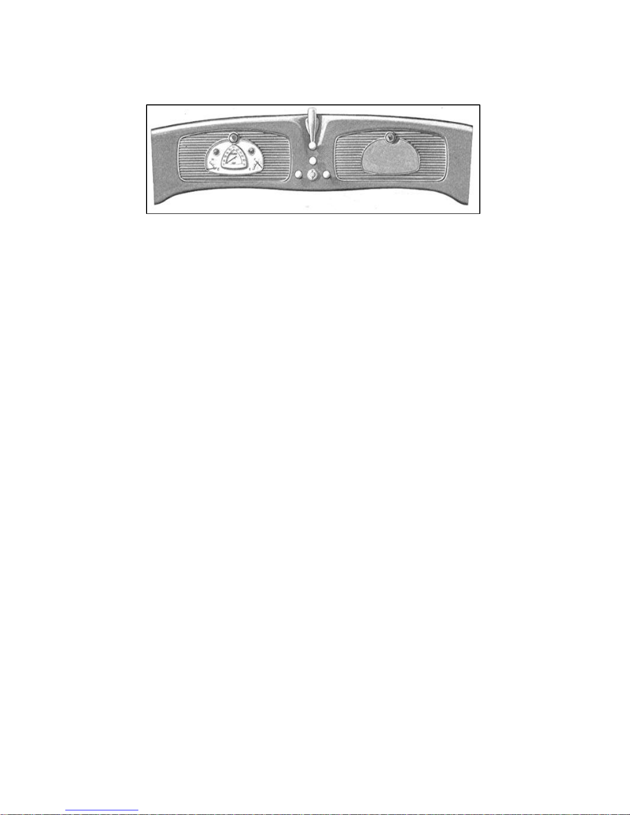
The engine speed can be controlled either by the foot accelerator or the
throttle knob, which is located on the instrument panel above the ignition
The light control knob is located directly to the left of the ignition lock.
Pulling the knob out to the first position gives side lights and head lights in
the second position. The head light control is located on the toe board to the
left of the clutch pedal. If the head lights are on "bright" they are "dimmed"
by pressing this foot control. A second depression of this control returns the
The service lamp is located on the instrument panel above the instrument
The starter is controlled by the ignition lock. When the ignition key is turned
to the right, the ignition is turned "on" and the starter is brought into operation.
Should the engine stop while the key is turned to the right, the automatic
starter will immediately engage and re-start the engine. If the car is in gear
when the engine stalls, the clutch pedal should be depressed until the engine
If it is not desired to use the automatic starter after the engine has been
started, the ignition key can be turned to the left. Turning the key to the left
will also permit reading the gasoline or oil gauge and timing of the ignition
If it is desired to turn the engine by the starter without starting the engine,
push the plunger which extends out of the rear face of the automatic starter
relay box (under hood at left of engine). Hold the plunger down firmly and
release quickly by sliding the finger off sidewise to prevent the plunger
sticking. Should the plunger stick so that the engine continues to turn, push it
The carburetor choke control knob is located to the right of the ignition lock.
The oil pressure signal is the red jewel located to the left of the center of the
instrument group. When the ignition switch is turned "on" this signal will be
lighted and should stop glowing when the engine is running. If it remains
lighted or flashes while the engine is running above idling speed, the engine
should be stopped and the oil level in the reservoir checked. If necessary,
The generator signal is the red jewel located to the right of the center of the
instrument group. When the ignition switch is turned "on" this signal will be
switch.
lights to "bright."
group. When the lamp is pulled out it automatically lights.
starts.
without starting the engine.
in again and release quickly.
(See "Starting the Engine" for use of choke.)
check the oil lines. Do not run the engine until the trouble is corrected.
lighted and should stop glowing when the engine reaches a speed slightly
8

HUDSON EIGHT OPERATION
above normal idling. If the signal flashes when the car is being driven above
twenty miles per hour, it indicates that the battery is not being charged. Your
The "gasoline or oil" gauge, located in the lower right corner of the
instrument group, indicates the quantity of gasoline in the tank when the
ignition switch is turned either to the right or left position. By pushing
upward on the button located below the ignition switch and extending from
the bottom of the instrument panel, the hand of this gauge indicates the
The engine temperature indicator is located in the lower left corner of the
The proper procedure in starting the engine is as follows: See that the
throttle control knob is in. Do not open throttle with the accelerator until the
engine starts. Pull the choke knob out as far as possible. Insert the ignition
key in the lock and turn clockwise. When the engine "fires" push the choke
in until it runs evenly. If the engine is cold, the choke can only be pushed in
about three- eighths of an inch. Never leave the choke out farther than
necessary to keep the engine running smoothly. It should be pushed in to the
electrical system should be checked by your Hudson dealer.
quantity of oil in the reservoir of the engine.
instrument group.
Starting the Engine
limit of its travel as soon as possible after starting the engine.
9
 Loading...