

Page 1
Page 2

Page 3
OWNER'S MANUAL
THE GREATER
HUDSON 8
FOR 1932
SERIAL NUMBERS
119" W. B.-930770
126" W. B.- 62884
132" W. B.-250001
AND
UP
HUDSON MOTOR CAR COMPANY
DETROIT, MICHIGAN, U. S. A.
Page 4

Page 5

Foreword
Hudson automobiles are equipped with locks
which have been approved by the Underwriters
Bureau as satisfactory means of preventing theft.
The presence of these locking devices reduces the
insurance rate to the owner, but does not reduce the
possibility of loss by theft unless you LOCK
YOUR CAR.
Protection against loss by damage to the mechanism has been provided in Hudson automobiles by
providing adequate means of lubrication for all
working parts. Although the system of lubrication
used is as positive and complete as any in use
today, its protection depends to a large extent on
how regularly you LUBRICATE YOUR CAR.
This instruction book is intended only as a guide
to the owner in the operation and care of his car
and not as a service manual. Do not attempt adjustments or repairs with which you are not thoroughly
familiar or for which you do not have equipment
to handle properly. Both for periodic inspection
and for adjustments TAKE YOUR CAR TO AN
AUTHORIZED HUDSON SERVICE STATION.
Protect your car when making replacements and
preserve the original performance—USE ONLY
GENUINE HUDSON PARTS.
Page 6

INDEX
General
BREAKING-IN INSTRUCTIONS
CARE OP THE FINISH
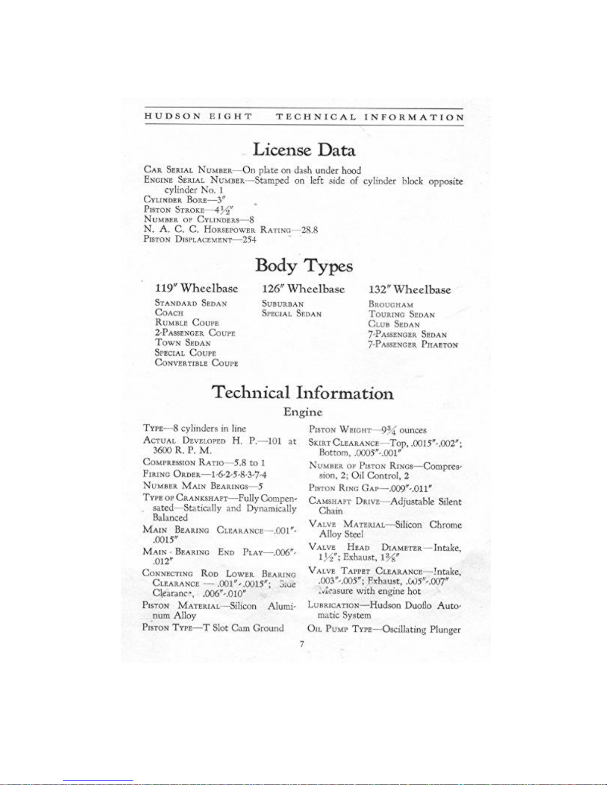
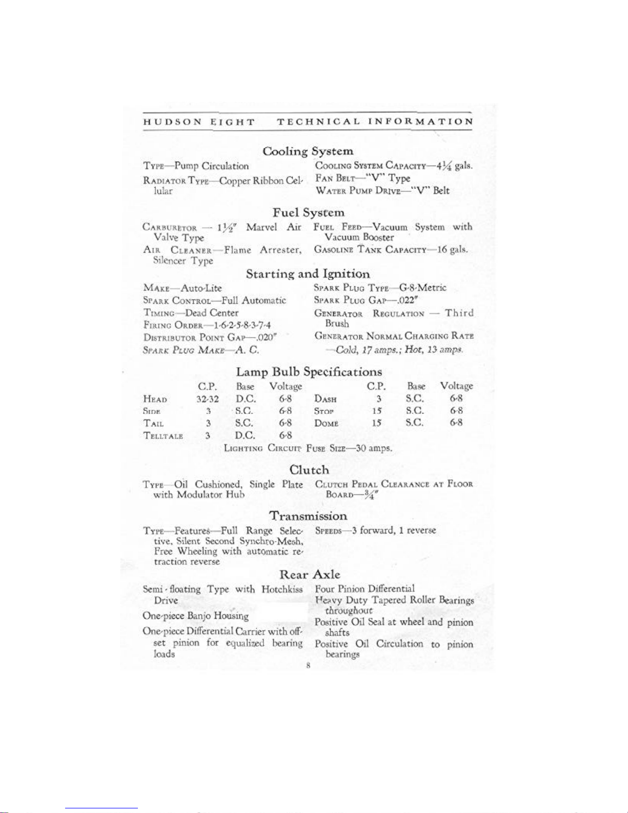
LICENSE DATA AND TECHNICAL INFORMATION
OPERATION
STARTING THE ENGINE
WARRANTY
Lubrication
BRAKE CROSS SHAFT
CHASSIS LUBRICATION CHART
CLUTCH
DISTRIBUTOR
DOOR DOVETAILS
DOOR LOCKS
ENGINE
FRONT WHEEL BEARINGS
GENERATOR
HOOD LEDGE LACINGS
HOOD LOCKS
REAR AXLE
REAR WHEEL BEARINGS
STARTING MOTOR
STEERING GEAR
THROTTLE CONTROL RODS AND LEVERS
TRANSMISSION
UNIVERSAL JOINTS
WATER PUMP
Page
13
35
7
10
12
6
23
14
17
16
23
23
15
21
16
23
23
21
22
17
22
23
20
20
16
Adjustment
ADJUST DISTRIBUTOR POINTS
BATTERY
BRAKES
CARBURETOR
CLUTCH PEDAL ADJUSTMENT
DISTRIBUTOR
FAN AND WATER PUMP
FRONT WHEEL ALIGNMENT
FRONT WHEEL BEARINGS
HEADLAMPS
IGNITION TIMING
RADIATOR
REAR WHEEL BEARINGS
SHOCK ABSORBERS
SPARK PLUGS
SPRING MOUNTINGS
STEERING GEAR
SYNCHRONIZE BREAKER POINTS
TAPPETS
TIMING CHAIN
TIRES
VACUUM TANK
WHEELS-REMOVAL AND INSTALLATION
WIRING DIAGRAM
24
29
32
27
28
24
27
32
30
35
24
34
30
34
25
33
29
25
26
26
31
28
31
18.19
Page 7

Warranty
"We warrant each new passenger automobile manufactured by us to be free from defects in material and
work- manship under normal use and service, our obligation under this warranty being limited to making good at
our factory any part or parts thereof, including all equipment or trade accessories (except tires) supplied by the
Car Manufacturer, which shall, within ninety (90) days
after making delivery of such vehicle to the original
purchaser or bfore such vehicle has been driven 4000
miles, whichever event shall first occur, be returned to us
with transportation charges prepaid, and which our examination shall disclose to our satisfaction to have been thus
defective, this warranty being expressly in lieu of all other
warranties expressed or implied and of all other obligations or liabilities on our part, and we neither assume nor
authorize any other person to assume for us any liability
in connection with the sale of our vehicles.
"This warranty shall not apply to any vehicle
which shall have been repaired or altered by other than
an authorized Hudson and Essex Distributor or Dealer
in any way so as, in the judgment of the Manufacturer,
to affect its stability or reliability nor which has been
subject to misuse, negligence or accident."
HUDSON MOTOR CAR COMPANY
Detroit, Michigan, U. S. A.
Page 8
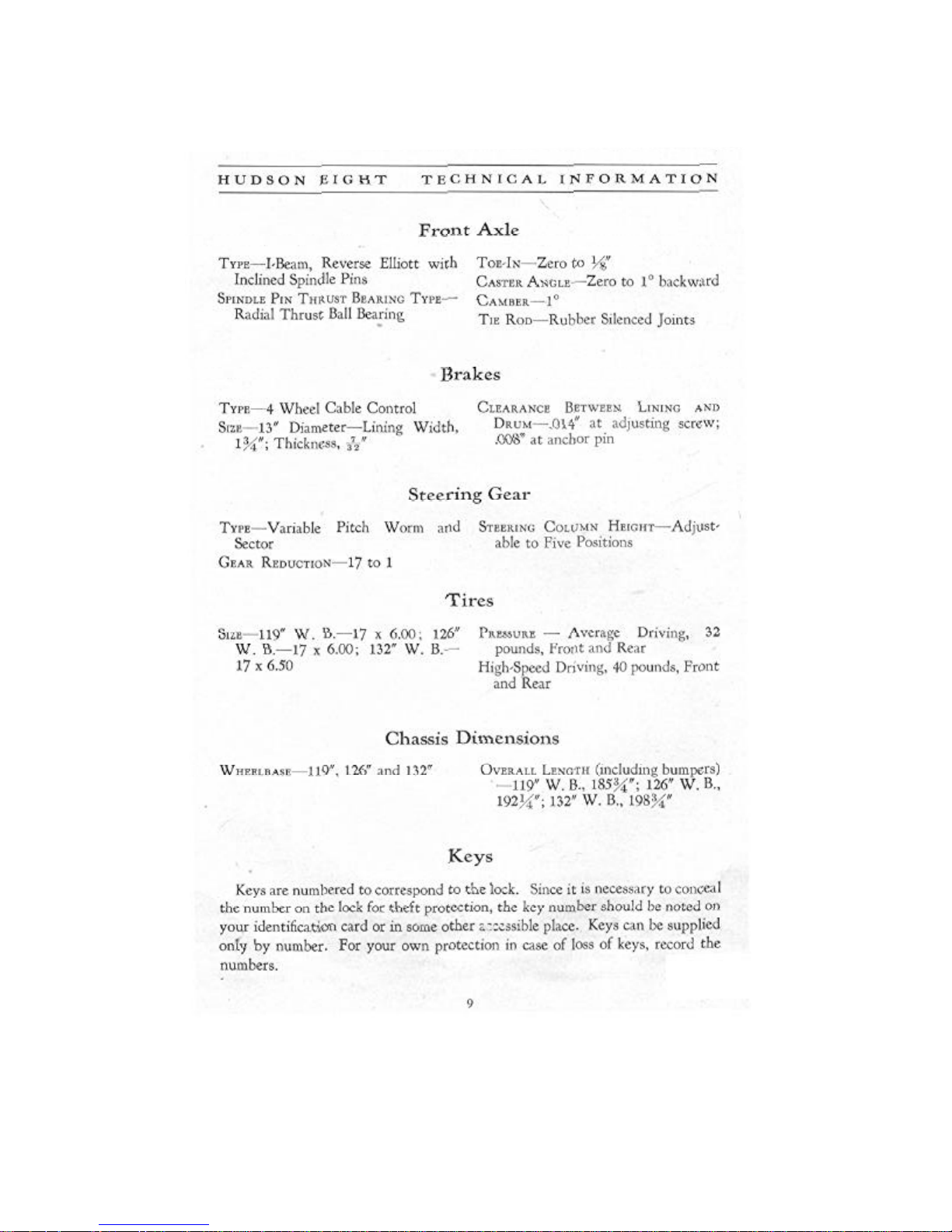
Page 9
Page 10
Page 11
The operation of the Hudson Eight follows standard practice in many respects; however, even
those accustomed to Hudson products may refresh their memories on some of the details by
The clutch is disengaged in the conventional manner by depressing the left foot pedal to
release the engine drive from the transmission. Form the habit of keeping the foot off the clutch
The transmission operation conforms to the standard shift. The clutch must be disengaged to
HUDSON EIGHT OPERATION
Operation
reading the following paragraphs:
pedal except when shifting gears or coming to a stop.
shift gears except when the car is in motion and "free wheeling."
10
Page 12

HUDSON EIGHT OPERATION
Free wheeling is obtained by pressing the button on top of the shifting lever knob and pulling
the knob up until the button comes out flush with the top of the knob. To revert from free
wheeling" press the button and push down on the knob until the button comes out flush.
It is possible to change to "free wheeling" at any time. To change from "free wheeling" to
conventional drive when the engine is driving the car simply depress the button and knob. If the
knob does not come out flush, release the accelerator pedal slightly while still pushing down on
the knob.
If the car is in motion and the engine is running at idling speed, increase the speed of the
engine so that it drives the car, or depress the clutch before changing from "free wheeling" to
conventional drive.
The brakes are operated either by depressing the right foot pedal or pulling backward on the
hand lever located on the driver's left just ahead of the front door.
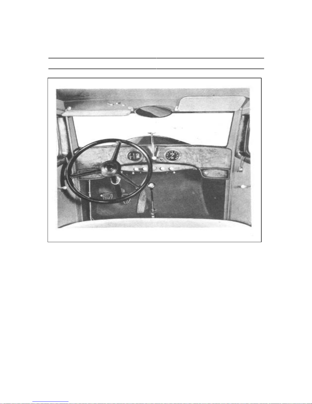
The engine speed can be controlled either by the foot accelerator or the throttle knob which is
located on the instrument panel directly to the right of the ignition lock.
The light control knob is located directly to the left of the ignition lock. Pulling the knob out
to the first position gives side lights and head lights in the second position. The head light control
is located on the toe board to the left of the clutch pedal. If the head lights are on "bright" they
are "dimmed" by pressing this foot control. A second depression of this control returns the lights
to "bright."
The dash lights are controlled by the switch extending below the instrument panel, slightly to
the right of the throttle control knob.
The starter is controlled by the ignition lock. When the ignition key is turned to the right, the
ignition is turned "on" and the starter is brought into operation. Should the engine stop while the
key is turned to the right, the automatic starter will immediately engage and re-start the engine.
If the car is in gear when the engine stalls, the clutch pedal should be depressed until the engine
starts.
If it is not desired to use the automatic starter after the engine has been started, the ignition
key can be turned to the left. Turning the key to the left will also permit reading the gasoline or
oil gauge and timing of the ignition without starting the engine. If it is desired to turn the engine
by the starter without starting the engine push the plunger which extends out of the rear face of
the automatic starter relay box (under hood at left of engine). Hold the plunger down firmly and
11
Page 13

plunger stick so that the engine continues to turn, push it in again and release quickly.
HUDSON EIGHT OPERATION
release quickly by sliding the finger off sidewise to prevent the plunger sticking. Should the
The carburetor choke control knob is located to the left of the light control knob. (See "Starting
the Engine" for use of choke.)
The oil pressure signal is the red jewel located to the left of the center of the instrument panel.
When the ignition switch is turned "on" this signal will be lighted and should stop glowing when
the engine is running. If it remains lighted or flashes while the engine is running above idling
speed, the engine should be stopped and the oil level in the reservoir checked. If necessary, check
the oil lines. Do not run the engine until the trouble is corrected.
The generator signal is the red jewel located to the right of the center of the instrument panel.
When the ignition switch is turned "on" this signal will be lighted and should stop glowing when
the engine reaches a speed slightly above normal idling. If the signal flashes when the car is
being driven above twenty miles per hour, it indicates that the battery is not being charged. Your
electrical system should be checked by your Hudson dealer.
The "gasoline or oil" gauge indicates the quantity of gasoline in the tank when the ignition
switch is turned either to the right or left position. By pushing upward on the button located
below the instrument panel and slightly to the left of the light control knob, the hand of this
gauge indicates the quantity of oil in the reservoir of the engine.
The engine temperature indicator should show a reading within the driving range at all times
when the car is being driven.
The ride control knob on the instrument panel to the right of the throttle knob gives maximum
shock absorber control when pushed in and a "boulevard control" when pulled out. Any desired
control can be obtained by moving the control knob.
Starting the Engine
The proper procedure in starting the engine is as follows: See that the throttle control knob is
in. Do not open throttle with the accelerator until the engine starts. Pull the choke knob out as far
as possible. Insert the ignition key in the lock and turn clockwise. When the engine "fires" push
the choke in until it runs evenly. If the engine is cold, the choke can only be pushed in about
three-eighths of an inch. Never leave the choke out farther than necessary to keep the engine
running smoothly. It should be pushed in to the limit of its travel as soon as possible after starting
the engine.
12
Page 14

HUDSON EIGHT OPERATION
Breaking-in Instructions
Keep Radiator Full Keep Oil Reservoir Full
Heat is a major consideration in a new engine. Do not allow the engine to
overheat. Although the heat indicator on the instrument panel shows the general
temperature of the engine, it will not show a sudden rise in temperature of an
individual part.
The pressure imposed on parts such as bearings and pistons due to rapid
acceleration or hard pulling will cause them to overheat if the car has not been
driven sufficiently to break them in. Avoid fast acceleration and hard pulling
while breaking in.
High speed also develops higher operating temperatures and to avoid damage
the car speed should be kept within the following recommendations:
0-250 MILES
Do not exceed 40 miles per hour in high gear or 20 miles per hour in second.
Do not accelerate rapidly. Use second gear on steep grades. Keep motor
temperature within "driving range" on dash heat indicator.
250-500 MILES
Do not exceed 50 miles per hour in high gear or 25 miles per hour in second.
500-1000 MILES
During this period the speed should not exceed 60 miles per hour.
IMPORTANT
Do not UNDER ANY CONSIDERATION attempt to maintain a high rate of
speed unless the crankcase is full of good oil, and until the engine is thoroughly
warmed up. Cold oil is not able to flow freely into the small clearances between
working parts so that damage may occur if sufficient time is not allowed for
warming up before attempting high speeds.
13
Page 15

Page 16

HUDSON EIGHT LUBRICATION
Lubrication
Engine
Use High-Grade Oil—Medium Heavy Body or S. A. E. 30
Consult your dealer if you are in doubt as to what
oil to use.
When the ignition switch is turned "on" the red
jewel to the left of the center of the instrument board
should flash red. If it does not, the bulb is either
burned out, the circuit to the oil relief valve broken
or the oil relief plunger sticking.
As soon as the engine is running, the light should
go out. A flash of the red jewel while the engine is
running above idling speed indicates interruption of
the oil supply. The engine should be stopped immediately and the lubrication system inspected.
The amount of oil in the reservoir is shown on the gauge on the instrument panel marked "Gas
or Oil" when the ignition electrolock is turned "on" (turn to left to read gauges without starting
engine) and the button under the instrument panel below the gauge is pressed up.
A bayonet gauge is also provided at the oil filler. See illustration.
The Hudson Duoflo oiling system provides not only purification from dilution but also double
screening and cooling of the oil. The oil is therefore maintained in good condition for a longer
time than in other lubricating systems. Oil should be added as necessary to maintain the quantity
in the reservoir. The reservoir should he drained and refilled with eight (8) quarts of oil at least
every 2500 miles.
It is, however, recommended to drain the initial supply of oil after the first 500 miles of
driving. To drain the reservoir remove the plug from the rear of the oil reservoir. Be sure the
drain plug is tightened securely when replaced.
15
Page 17

HUDSON EIGHT LUBRICATION
Water Pump
Use Motor Oil
Supply three or four drops of light motor oil in the
oil cup "A," shown in the illustration, every 1000
miles. This is the only point on the pump requiring
lubrication. Do not over-lubricate, and wipe off excess oil as this may get on the belt and cause slippage
on the pump and fan pulleys.
Distributor
Use Motor Oil
Fill distributor base to the level of the oil cup "C"
with motor oil every 2000 miles.
Coat rotor cam "B" lightly with vaseline or light
cup grease every 2000 miles.
Apply a drop of oil at breaker arm pivots "A"
every 2000 miles. Note: One breaker arm pivot not
shown in illustration.
Care should be taken not to get oil on any parts of the
distributor other than those specifically referred to as
requiring lubrication. Do not over- lubricate.
Generator
Use Motor Oil
Three or four drops of light motor oil at points "A"
and "B" in the illustration every 1000 miles.
Do not attempt to supply more oil than is required
to fill the cups once as excess oil may praevent
proper operation of the unit.
16
Page 18

HUDSON EIGHT LUBRICATION
Starting Motor
Use Motor Oil
Three or four drops of light motor oil at points "A"
and "B" in the illustration every 1000 miles.
The oil cups on the starting motor have been made
small to prevent overlubrication, which might find
its way to the windings or commutator and eventually cause failure of the unit. Do not attempt to
supply more oil than is required to fill the cups once.
Clutch
Use 1/6 Pint of Light Motor Oil
and 1/6 Pint of Kerosene
The clutch lubricant is sealed into the clutch and
supplies the driving surfaces as well as the throwout
bearing with oil.
The life of the lubricant is largely dependent on
the usage of the clutch. Harsh clutch action indicates
the need of fresh oil and the clutch should be
promptly inspected by your Hudson dealer if this
condition develops. In any event the oil should be
changed at least every 15,000 miles.
To drain the clutch, crank the engine by hand until the oil filler plug "A" on the front side
of the flywheel is visible through the timing inspection hole. Remove the plug and turn
engine slowly to allow lubricant to drain. Bring plug hole back to opening and insert new
lubricant. Replace the drain plug securely.
17
Page 19

Page 20

HUDSON EIGHT LUBRICATION
Transmission
The lubricant in the transmission and free
wheeling units should be maintained to the level
of the filler plugs "A" and "B."
The plugs "C" and "D" should be removed
every 5000 miles and the lubricant drained out.
Replace the plugs and fill through plug "B" with
one quart of kerosene. Run engine with transmission in neutral and clutch engaged for one minute. Drain kerosene, replace drain plugs and fill
through "B" with three pints of S. A. E. No. 90
gear oil (in winter use S. A. E. No. 80), allowing
the oil to drain into the main transmission housing. If the full three pints cannot be
put in at "B," add the balance at "A."
It is essential that good oil of the proper body be used to insure proper protection
against wear and permit proper gear changing. Buying according to the S. A. E.
specifications (this is shown on most oil containers) will insure you of obtaining a
satisfactory lubricant.
Universal Joints
Use Fiber Grease
Remove the plug "A," shown in the illustra-
tion, of the rear universal joint and inject good
fiber grease until grease appears at vent hole in
shaft opposite filler hole. There is a plug simi-
larly located just back of the front universal joint
for filling.
The use of a proper grease at these points is
very important in order to insure lubrication.
These units should be filled every 2000 miles.
The universal joints are often neglected until wear has occurred to such an extent
that replacement is necessary. Wear at these points throws the propeller shaft out
of balance, causing vibration, and thus offsets the care taken in manufacture to
obtain accurate balance which is necessary for smooth operation at high speeds.
20
Page 21

HUDSON EIGHT LUBRICATION
Rear Axle
Use High-Grade Gear Oil—
Heavy Body or
S. A. E. 90 in Summer—
S. A. E. 80 in Winter
The oil supply in the axle housing should be kept level with
the lower edge of the filler plug opening "A."
There are special oil passages and baffles in the differential
carrier housing which catch oil thrown from the ring gear and
carry it to the pinion bearings and return the overflow to the axle housing. This keeps the pinion
bearings under a constant bath of oil and eliminates the necessity of oiling them separately.
Every 5000 miles drain, flush out with kerosene and refill.
Housing may be drained by removing cover "B."
Front Wheel Bearings
Use Cup Grease
The front wheel bearings should be lubricated every 5000
miles. Jack up the front of the car and remove the wheel from
the hub. (See page 31 for method of removing and installing
wheels.)
Unscrew the inside hub cap and withdraw the cotter key
holding the nut "B." Unscrew the nut "B" and remove the
washer "C." The hub and brake drum can then be removed and
the bearing and inside of the hub and drum washed out with
kerosene. Pack the bearings and hub with three ounces of cup
grease. Replace the felt washer at the inner end of the hub, if necessary. Replace wheel. (See
page 30 for bearing adjustment.)
21
Page 22

HUDSON EIGHT LUBRICATION
Rear Wheel Bearings
Use Cup Grease
The rear wheel bearings should be lubricated every
5000 miles. Jack up rear of car and remove the wheel
from the hub. (See page 31 for method of removing and
installing wheels.) Withdraw cotter key and remove nut
from end of axle shaft. Pull hub and brake drum off the
shaft.
Unscrew four screws holding grease deflector "A" and
remove deflector. Remove four screws from bearing cap
"B" and remove cap and shims "C." Remove bearing and
insert ten (10) ounces of grease in the housing.
Wash the cap and bearing in kerosene and replace bearing after filling with grease. Renew the
felt washer in the bearing cap, if necessary. Replace shims and bearing cap. Replace the grease
deflector. See that all brake parts and the brake drum are free from grease before replacing the
hub and wheel.
Steering Gear
Use High-Grade Gear Oil—Heavy Body
Remove plug "A" and fill the steering gear housing every
2000 miles. The use of a good grade heavy bodied gear oil is
necessary to provide free operation under all climatic conditions. (Do not use grease.)
If the steering becomes stiff and complete lubrication of
the unit and the attached parts connecting with the front
wheels does not correct the condition, follow the instructions
on page 29 for adjustment and alignment of the steering gear.
Noise in the unit may be due to use of oil of insufflcient body.
Stiff operation ma, be experienced in cold weather if poop oil
or grease is used.
22
Page 23

HUDSON EIGHT LUBRICATION
Miscellaneous
THROTTLE CONTROL RODS AND LEVERS—Oil or grease all accelerator connections.
Throttle linkage should work with a snap. Grease choke and throttle wires occasionally to
eliminate sticking.
BRAKE CROSS SHAFT—Coat brake cross shaft pivot pins with light cup grease every 1000
miles. Do not allow oil or grease to collect inside of brake drum.
HOOD LEDGE LACINGS—Use motor oil. Saturate with motor oil frequently to remove
squeaks and preserve lacing.
HOOD LOCKS—Use motor oil. Lubricate occasionally by injecting a few drops of oil through
hole in the barrel just below the handle.
DOOR LOCKS—Use motor oil. Lubricate occasionally with a few drops of oil on the latch
bar. Work lock several times to spread oil, then wipe off excess.
DOOR DOVETAILS—Lubricate with grease or soap. Wipe off excess.
DOOR HINGES—Lubricate with light oil. Wipe off excess.
23
Page 24

HUDSON EIGHT ADJUSTMENT
Adjustment
Ignition Timing
Should it be necessary to reset the ignition
timing, loosen the distributor adjusting plate
lock screw "B." If the adjustment is being made
because of sluggish performance, turn the distributor counterclockwise one division of the
scale on the locking plate. Tighten screw "B"
and try the performance of the car on the road.
A slight spark knock should be heard when the
car is being accelerated on a level road in high
gear at ten to twenty-five miles an hour with
the throttle wide open. This gives the best
performance and fuel economy.
If a spark knock is not heard, turn the distribu-
tor one division counterclockwise as before and
test again. If the knock is too loud, turn the distributor clockwise one-half division at a time to
reduce the knock until it can just be heard by the driver.
Should the distributor require any other adjustments, the car should be taken to an authorized
Hudson or Electric Auto-Lite Service Station. The following instructions are given for use in
case of an emergency, but should not be attempted by the owner unless absolutely necessary.
The results obtained from these adjustments depend entirely on the accuracy with which they are
performed.
Adjust Distributor Points
Breaker points should be clean, flat and spaced .020" when at their maximum opening.
Remove distributor cap and inspect points and clean if necessary. A special breaker point file
or stone should be used. Place file or stone between points and move straight up and down,
dressing both points at the same time.
Crank engine by hand until the breaker arm fiber block of points "H" is on the highest point
of the cam, giving the points their maximum opening. Adjust the opening to exactly .020" by
loosening the lock nut and turning the adjusting screw on which the stationary point is mounted.
Tighten lock nut.
24
Page 25

HUDSON EIGHT ADJUSTMENT
just begin to open. This point must be determined accurately. Tighten screws "G."
polish or equal parts of ammonia and water, and allow it to stand for a few seconds. Take a piece
Crank the engine by hand until the breaker arm fiber block of points "D" is on the highest
point of the cam. Loosen screws "E" one-half turn and adjust points "D" to exactly .020" by
turning the eccentric screw "F." Tighten screws "E" and recheck opening to be sure it is exactly
.020".
Synchronize Breaker Points
Remove the spark plug from number one cylinder and
hold a finger over the plug hole. Crank the engine by hand
until a rush of air is felt. Continue to turn engine slowly
until the D. C. 1 and 8 mark is exactly in line with the
pointer on the inspection hole as shown at "A."
Loosen clamp screw "B" and turn distributor clockwise
to the full limit permitted by the slot in the clamping plate
"C." Turn the distributor slowly counterclockwise until
the points "D" have just begun to open. Care must be
taken to determine this position accurately. Tighten lock
screw "B."
Turn the engine slowly with the hand crank until the D.
C. 3 and 6 mark is exactly in line with the pointer on the inspection hole. This should require
only one-quarter (90°) turn of the crank.
Loosen screws "G" one-half turn and turn breaker point support plate clockwise to the extreme
limits of the screw holes. Turn breaker point support plate counterclockwise until the points "H"
The illustration shows the rotor arm in the proper position for firing on number one cylinder.
The cable to number one spark plug should be in the cap socket directly above the rotor point.
The spark plug cables should be in the cap in the order 1-6-2-5-8-3-7-4, following in a clockwise
direction.
Spark Plugs
When setting the gap of the spark plugs, make all adjustments by moving the side wire. Do
not bend center wire as this may break the porcelain.
To clean the carbon from the porcelain, fill the lower part of the plug with alcohol, liquid metal
of wire covered with one thickness of cloth and rub the carbon from the insulator, wiping
thoroughly dry before replacing the plug in the engine.
Spark plugs should be changed every 10,000 miles for better engine performance. New spark
plugs give quicker starting, increased power, smooth running and a saving in gasoline.
25
Page 26

HUDSON EIGHT ADJUSTMENT
Tappets
Before adjusting tappets see that the tappet clamp cap
screw "C" is tight. Adjust tappet by loosening lock nut
"B" and turning adjusting screw "A." Lock adjustment
by tightening
lock nut "B" while holding screw "A."
Measure clearance between adjusting screw and end
of valve stem with a feeler gauge as shown at "D" in the
illustration. This measurement should be made while
the engine is at its normal operating temperature.
Adjust exhaust valve tappets to .006" and intake tappets to .004" clearance. Counting from the
front the exhaust tappets are 1-4-5-8-9-12-13-16 and the intake tappets are 2-3-6-7-10-11-14-15.
Always adjust tappets after grinding valves.
Timing Chain
The timing chain should be inspected at the expiration
of the first 1500 miles and at intervals of 5000 miles
there-after.
A to and fro movement of approximately 1/8" on the
circumference of the coupling "A" (after the slack around
the coupling bolt is taken up) should be maintained.
To adjust, loosen retaining bolts "B." The inside top bolt
and the bottom bolt (not shown) pass through the notches
in the eccentric, necessitating their removal. Insert special
tool "C" in notch and pull toward you until only the
required movement of the coupling is present. If trouble is
experienced in replacing the bolts, back off the adjustment
slightly, allowing them to slide into place:
One-half pint of motor oil should be introduced through the pipe plug opening "D" whenever
the distributor support housing has been removed.
26
Page 27

HUDSON EIGHT ADJUSTMENT
Fan and Water Pump
To adjust the belt, loosen the nut "A" and raise the fan
until the belt can be deflected 5/8" below a straight edge
laid on the fan and pump pulleys. This measurement of
deflection is indicated in the illustration at "B."
Do not adjust the belt too tight as it will throw an
excessive load on the fan and pump bearings.
Adjust the water pump packing gland "C" finger tight.
Do not tighten with a wrench as the packing may bind the
shaft and throw a heavy load on the belt.
Carburetor
Spark plugs and breaker points should be cleaned, spark
gaps properly spaced and all residue in gasoline passages
removed before adjusting the carburetor.
See page 28 for removal of vacuum tank filter to stop
flow of gasoline while cleaning carburetor.
Clean carburetor filter screen "B."
Adjust set screw "C" for correct idling speed of seven
miles per hour.
Turn air screw "A" until the end is flush with the end of
the ratchet spring bearing against it. This is the normal
mixture adjustment and the final setting should be within
turn of this point. Warm engine to proper operating temperature. Turn air screw counterclockwise until the engine
hesitates, then clockwise one notch at a time until the
engine runs smoothly.
The heat supplied to the carburetor from the exhaust is automatically controlled by a
thermostat and requires no adjustment.
The air cleaner unit should be cleaned every 2500 miles, except under extremely dusty
operating conditions when the cleaning should be more frequent. The unit can be lifted off the
carburetor silencer after removing the thumbscrews "D." Wash in gasoline and then soak with
motor oil. Drain off excess oil and replace.
27
Page 28

HUDSON EIGHT ADJUSTMENT
Vacuum Tank
The glass sediment chamber at the bottom of the
vacuum tank should be removed and cleaned whenever
its contents show an accumulation of water or dirt. The
water, due to the fact that it is heavier than gasoline,
settles to the bottom of the glass and is easily distinguished.
The flow of gasoline is automatically shut off as soon
as the glass is removed, so that it is only necessary to
hold the glass "A" in one hand, loosen the thumbscrew
and swing the bracket "C" to one side to empty the glass.
The removal of the sediment chamber also acts as a
cut-off so that the carburetor feed line can be removed
without loss of gasoline from the vacuum tank.
Clutch Pedal Adjustment
A clearance of 3/4" must be maintained between the
clutch pedal shank and the toe board, as shown in the
illustration at "A."
This adjustment should be made accurately as too
much clearance will reduce the pedal movement and
may prevent complete clutch disengagement, causing
hard shifting. Too little clearance may, after slight wear
of the clutch disc facing, permit the clutch pedal to rest
against the toe board and hold the clutch in partial
disengagement. This will cause slippage and rapid wear.
To adjust, remove the clevis pin "B." and loosen the
lock nut "C." Turn the yoke on the link to obtain proper length. Lengthening the link increases
the clearance between the clutch pedal shank and the toe board, while shortening the link reduces
it.
Page 29

HUDSON EIGHT ADJUSTMENT
Steering Gear
The bearings on the steering gear worm shaft are
preloaded by the pressure of a spring located between
the outer race of the upper bearing and cover plate. This
spring pressure prevents development of end play in the
worm, so that no adjustment is necessary to take care of
normal wear.
To remove side play in cross shaft: The adjustment for
cross shaft "F” is on the opposite end to that shown in
the illustration. Loosen the lock nut and with a screwdriver turn the adjusting screw down as tightly as possible, then back up slightly. Tighten lock nut.
To remove play in mesh of worm and cross shaft
sector: Locate wheels in straight-ahead position, disconnect drag link from steering arm and shake arm to
determine the amount of play. Loosen four stud nuts "D"
(VI turn only). Turn eccentric sleeve "C" to right or
clockwise direction only in gradual stages, noting result by shaking steering arm at each step and
using care at last stage to turn sleeve just sufficiently to remove play and no further. Securely
tighten cover stud nuts "D."
To change position of steering wheel to suit requirements of driver: It is necessary to loosen
frame bracket stud nuts "E," as well as cowl bracket nut under cowl, then set steering wheel at
desired position.
Keep the steering column to dash clamp bolt, the cross shaft nut "G" and the frame stud nuts
"E" tight.
Battery
Periodically disconnect terminals "A" from the
battery. Clean thoroughly, coat with vaseline, replace
and tighten securely.
Battery must be kept securely fastened in tray.
Tighten at "B."
Inspect battery liquid at least every two weeks in
warm weather (required less frequently in cooler
weather) and add distilled water at openings "C" to
29
Page 30

HUDSON EIGHT ADJUSTMENT
Front Wheel Bearings
The adjustment of the front wheel bearings is important, as it affects braking and steering, as well as the free
running of the car.
To adjust the front wheel bearings, jack up the front
wheel, remove the inner and outer hub caps and withdraw cotter key holding nut "B." Tighten nut "B" until a
slight drag is felt when turning the wheel slowly by
hand. Loosen the nut just sufficiently to permit the wheel
to turn freely, insert cotter key and replace hub caps.
Rear Wheel Bearings
To adjust rear wheel bearings, jack up rear of car and
remove both rear wheels. (See page 31 for method of removing wheels.) Remove wheel hubs as described under "Rear
Wheel Bearings." (See page 22.)
Unscrew four screws holding grease deflector "A" and
remove deflector. Remove four screws from bearing cap "B"
and remove cap. By reducing the number of shims under the
cap, the end play of the axle shaft is decreased, and the
installation of additional shims increases the end play.
Total end play between the axle shafts should be from .004" to .010", which amount is
perceptible when pulling the axle shaft in and out.
Approximately the same thickness of shims should be used under each bear, ing cap so that
the brake drums will be evenly spaced from the brake dust shields.
30
Page 31

HUDSON EIGHT ADJUSTMENT
place with the wrench, start at least two of the cap screws. Remove the wrench and start the
Removal and Installation of Wheels
To remove either the demountable wood or wire wheels,
place a screwdriver behind the hub cap and pry off.
Loosen the five cap screws "A" with the socket wrench
provided in the tool kit. Remove the cap screw "A" which
is at the lowest position on the wheel and insert the handle
of the wrench through the screw hole in the wheel into the
hub. While holding the wheel in position with the wrench,
remove the other cap screws "A" and lift off the wheel.
When reinstalling the wheel, jack up the car so that there
is just sufficient clearance for the wheel to slide
onto the hub. Place the handle of the wrench through the
lower cap screw hole in the wheel and the drum. Lift up on
the wrench so that the wheel will clear the ground and
push the wheel in place. Align the screw holes by moving
the wrench back and forth. While holding the wheel in
remainder of the screws.
Tighten every other cap screw until all are down just enough to hold the wheel in place to be
sure it is square on the hub. Tighten every other cap screw, continuing around until all screws
are securely tightened.
Tires
Check tires once a week and keep inflated to 32 pounds pressure. For fast driving inflate tires
to 40 pounds. Be sure front tire pressures are equalized.
To remove the tires from the wheels, let all air out of the tube. Push valve stem up into tire.
Starting at the valve stem press the beads of the tire together and into the base of the rim for about
one foot in each direction. Insert an iron under both beads directly opposite the valve and force
the tire over the rim. The tire can then be lifted off.
To install a tire, inflate the tube until it is barely round and place it in the casing with the valve
stem in line with the red dot on the side wall of the casing to preserve the tire balance. Press the
beads of the tire together at the valve stem and place tire on wheel so that the beads go to the
bottom of the rim well and the valve stem enters the hole in the rim. Working both ways from
the valve stem, press the beads together and down into the rim well until the portion of the tire
opposite the valve can be forced over the rim. Raise tire up and allow beads to spread until the
tire is centered on the rim. Inflate tube to five pounds pressure and work tire back and forth to
insure proper seating of tire on rim. Inflate to proper operating pressure.
31
Page 32

HUDSON EIGHT ADJUSTMENT
Brakes
When the brake pedal travels to within 1-1/2" of the
toe board, the brakes should be adjusted as follows:
Jack up all four wheels and remove the inspection
cover "A" from the brake drum. Turn the brake drum as
necessary and insert a .014" feeler between the drum and
the lining 1
from the adjusting screw end (rear of front brakes—
front of rear brakes) of the lining of the upper shoe.
Loosen the eccentric lock nut "B" and turn the
eccentric "C" in the direction the wheel rotates when the
car is moving forward until the feeler is held snugly.
Adjust all four wheels as outlined above. Depress the
brake pedal to within 3 of the toe board. Try the braking
effect by pulling each wheel over by hand. If the braking effect is unequal, or insufflcient, adjust
by removing the adjusting hole cover "D" and inserting adjusting tool or screwdriver in hole "E"
and engaging adjusting screw ratchet. Move hand end of tool toward the axle to increase, and
away from axle to decrease, braking effect.
Front Wheel Alignment
Measure the distances "A" and "D" as shown in the
illustration. The distance "A" should be the same as "D"
or not over 1/8" longer—never shorter.
A special tool should be used for this purpose and the
measurement taken between the rims at a height about
even with the hubs. Loosen clamp bolts "B" and turn tie
rod "C" clockwise as viewed from the right to increase
"A" and counterclockwise to decrease "A."
32
Page 33

HUDSON EIGHT ADJUSTMENT
Spring Mountings
Chassis noise, erratic spring action and wandering of
the car on the road can often be attributed to spring
mountings.
Adjust the spring shackles to remove end play of
spring on shackle bolt by loosening the locking nut,
"A" and turning the bolt "B" until tight, then turn back
one-sixth turn and tighten nut "A."
This operation should be performed every 5000
miles on both upper and lower shackle bolts at the rear
of both the front and rear springs and on the anchor
bolts (not illustrated), holding the front ends of front
and rear springs to the frame brackets.
The spring clip nuts (front and rear) shown in the
illustration should be tightened every 5000 miles.
When making the above adjustments the body holddown bolts should also be tightened. There are eight of
these, four on each side, located just outside the frame
side members and under the body sills. Draw the nuts
tight after the first 1500 miles and every 5000 miles
thereafter.
33
Page 34

HUDSON EIGHT ADJUSTMENT
purpose can be obtained from your dealer. Do not use any other liquid as there is a possibility of
Shock Absorbers
The shock absorbers should be refilled every 2000 miles. The special fluid required for this
destroying the unit, especially in cold weather, should the liquid become thick or frozen.
Keep the shock absorbers tight on the frame at all times and do not permit any play to develop
in the linkage.
All repairs and adjustments, including refilling of the shock absorbers, should be made by an
authorized Hudson or Gabriel Service Station.
Radiator
Drain, flush out and refill frequently.
Filler is located under the hood to eliminate possibility
of anti-freeze ruining the finish.
About every four months a solution consisting of one
pound of washing soda to four gallons of water should be
poured into the radiator and allowed to slowly circulate
through the system by running the engine at idling speed.
Leave drain cock open and thoroughly flush out after
cleaning.
See that hose is in good condition and all hose clamps
are tight.
Do not allow mud, etc., to clog air passages through
radiator.
Repair dents and leaks when they occur.
Add an anti-freeze solution to the radiator in cold weather.
Drain enough water from the radiator so that after the anti-freeze has been added there will
still be room for a slight expansion of the liquid without its running over the overflow pipe.
Add Anti-Freeze as Follows :
Ethylene
For
32° to 10° above 0°
10° to 0
9
0° to 10° below 0°
10° to 20° below 0°
34
Glycol or
5-1/2 qts.
7 qts.
8-1/3 qts.
9-1/2 qts.
6-2/3 qts.
8-2/3 qts.
10 qts.
11-1/4 qts.
Alcohol or
Radiator
Glycerine
9-1/4 qts.
11-1/2 qts.
13-2/3 qts.
15-1/3 qts.
Page 35

HUDSON EIGHT ADJUSTMENT
Headlamps
Place the vehicle under normal load on a level floor squarely facing a smooth wall 25 feet
from the headlamps.
Measure the height of the lamp bulbs from the ground and draw a horizontal line on the wall
at the same height as the bulbs.
Sight through windshield along hood rod and radiator cap to determine the center line of the
vehicle. Locate center lines of lamps on the wall from this line.
With the light control in the position throwing the light beam farthest from the vehicle, cover
left lamp to obscure its light beam.
Loosen the right mounting nut (under fender apron) and aim the right lamp so that the top of
the beam is just even with the horizontal line and equal portions on each side of line on the
wall indicating the center line of the right lamp.
Repeat operations with the left lamp and the headlamps will be properly aligned.
Care of the Finish
The same care should be exercised in washing and cleaning cars finished in lacquer or
enamel as is employed in the handling of varnished surfaces. Dry dirt accumulations should
not be wiped off but should be softened and removed by thoroughly soaking the body with
flowing water, applied under light pressure.
Careful washing of the car, followed by the use of a polish especially prepared for lacquer or
enamel finishes, will maintain a high luster and preserve the finish. The use of polishes containing strong abrasives should he avoided, as they are particularly destructive to the striping.
Anti-freeze solutions con- taining alcohol when accidentally spilled on the finish should be immediately washed off with clear water to prevent spotting, as alcohol is a solvent of lacquer.
It is recommended that every new car purchaser apply a coat of wax while lacquer is still
clean and unmarked. If this is done and the application periodically renewed, it will be an important factor in the life of the finish.
35
Page 36

 Loading...