

Page 1

IF YOU HAVE ANY QUESTIONS OR CONCERNS, OR ARE MISSING PARTS
DO NOT RETURN SPRAYER TO THE STORE!
PLEASE CALL OUR CONSUMER HOTLINE AT 1-800-9-SPRAYER
Visit us on the Internet: www.hdhudson.com
(1-800-977-7293)
Instruction 738-554 Model 18539
LIMITED WARRANTY
H. D. Hudson Manufacturing Company warrants to the original purchaser only that this product will continue to
function as intended if used in accordance with operating instructions (under NORMAL CONSUMER USE) for
one year . If the product fails to function as intended—DO NOT RETURN IT TO THE STORE—call our CONSUMER
SERVICE HOTLINE AT 1-800-9-SPRAYER (toll free) for fast service. We will, at our option, repair or replace any
non-functioning parts without charge (shipping and handling charges will apply) H. D. Hudson Manufacturing
Company shall have the option of requiring the return of the non-functioning product to the address listed below
together with the proof of purchase to establish a claim under this warranty. This warranty does not apply to
damage resulting from accident, misuse, neglect, alterations, operation not in accordance with instructions,
commercial use, or normal wear.
ANY IMPLIED WARRANTIES, INCLUDING THE IMPLIED WARRANTY OF MERCHANTABILITY AND FITNESS FOR
CONSUMER USE, ARE LIMITED TO THE DURATION SPECIFIED ABOVE. H. D. HUDSON MANUFACTURING
COMPANY’S LIABILITY IS LIMITED SOLELY TO THE REPAIR OR REPLACEMENT OF THE NON-FUNCTIONING
PRODUCT OR PART. H. D. HUDSON MANUFACTURING COMPANY EXCLUDES LIABILITY UNDER THIS WARRANTY
FOR ANY AND ALL INCIDENTAL AND CONSEQUENTIAL LOSS OR DAMAGE.
Some states do not allow limitations on how long an implied warranty lasts, or the exclusion or limitation of
incidental or consequential damages, so these limitations or exclusions may not apply to you. This warranty
gives you specific legal rights and you may have other rights which vary from state to state.
IF YOU HAVE QUESTIONS OR CONCERNS: PLEASE CALL OUR CONSUMER HOTLINE AT 1-800-9-SPRAYER.
(1-800-977-7293)
WARNING!
The engine must use mixed fuel. The ratio between gasoline and oil is 25:1. You can use either
leaded or unleaded gasoline. The oil should be for two stroke engines. The engine should run
without load for 3-5 minutes after starting and before stopping. Do not run engine without load at
high speed, it can damage the engine. You may also damage the engine by stopping the engine
at high speeds. Always reduce the engine speed before shutting off the unit. To prevent fire, keep
hot engine away from flammable materials when adding fuel. Smoking is strictly prohibited!
CAUTION!
Wear approved, protective clothing, respirator mask and oil-proof gloves to protect operator
from contamination from pesticide. Follow pesticide label directions. In all cases, consider
direction of wind to avoid spray being blown back on operator. Always flush pesticide tank
and supply lines at the end of each period of use. This will help prevent corrosion and damage
to the sprayer and its components. Dispose of pesticide formulations remaining in the tank
and flush the residues in accordance with label directions. Before opening container of
pesticide for use in this sprayer, always read and thoroughly understand directions on its
label. Follow exactly the instructions for mixing, application, disposal and safety. Be sure the
pesticide is appropriate for usage with this sprayer. Keep sprayer and spray material out of
reach of children
1
Page 2
MAIN USES
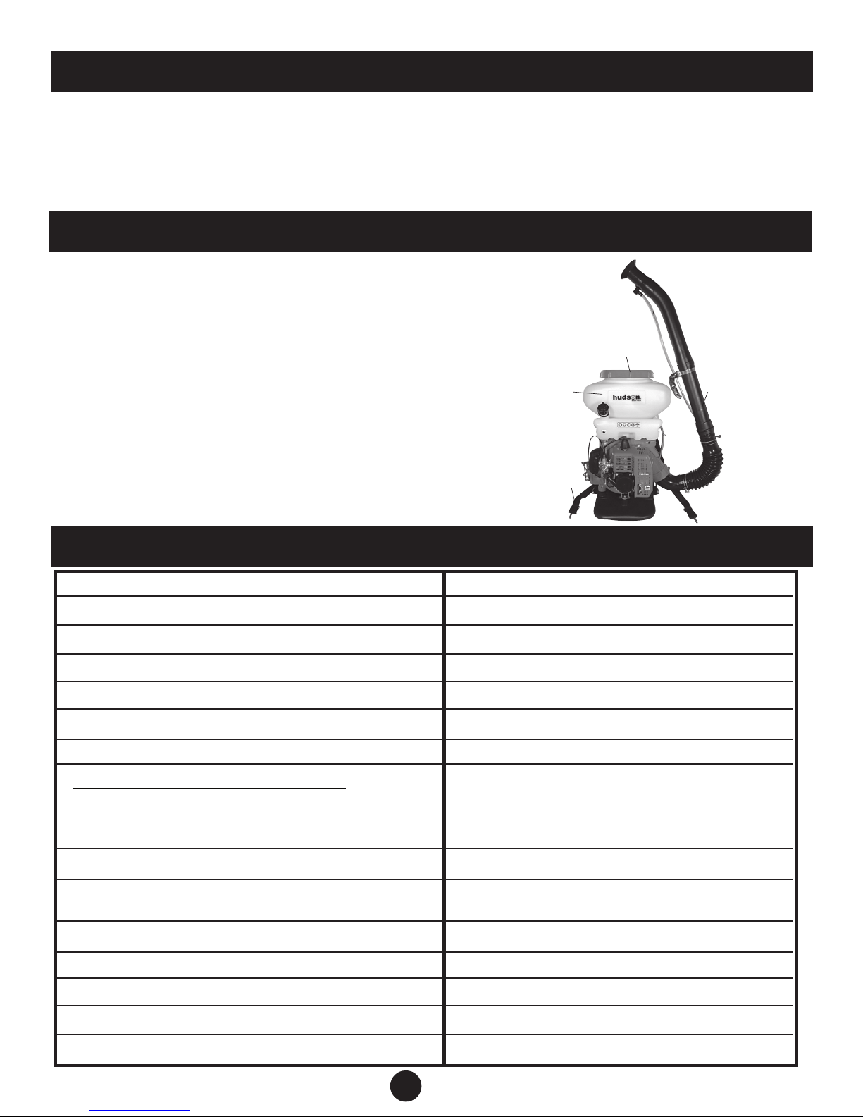
Thank you for purchasing the Hudson® 18539 Bak-Pak® power duster sprayer. The unit can
be used as a duster or converted to a mist blower. It is suitable for use in the prevention of
plant diseases and controlling pests on large plantations and crop fields where cotton, wheat,
fruit trees, etc. are planted. It can be used for applying herbicides. The unit is also suitable for
sanitation and janitorial work. It can be used to apply granular media.
MAIN FEATURES
1). Tough poly fuel and chemical tanks are translucent,
making it easy to see fluid levels.
2). Poly framework makes the unit strong and light weight.
3). All parts that make contact with the chemicals are poly
or stainless steel.
4). Large 8-3/8” tank opening for easy filling and a filter to
keep dirt and debris out of tank.
5). Adjustable and padded shoulder straps.
6). Unit can be easily changed over from a duster to
a mist blower.
7). Tool kit included.
TECHNICAL SPECIFICATIONS
MODEL
OVERALL DIMENSIONS (IN)
NET WEIGHT (LBS/KG)
CAPACITY OF TANK (GAL/LITER)
FUEL TANK CAPACITY (GAL/LITER)
DISPLACEMENT
18539
11/16 X 16 3/16 X 25 7/16
19
23.2 LBS / 10.5 KG
3.7 GAL / 14.0 LITER
0.26 GAL / 1.0 LITER
42.7 cc
4
1
5
6
POWER
DISCHARGE RATE OF CHEMICAL
SPRAYER MIXTURE (GAL/LITER PER MIN)
DUST (LBS/KG PER MIN)
RANGE (FT/M)
VOLUME RATIO OF MIXTURE FUEL
BETWEEN PETROL AND MOBILE OIL
FAN SPEED (R/MIN)
ENGINE MODEL
IGNITION
STARTER
STOPPING
1.8 kw
UP TO 0.6 GAL / 2.3 LITER per min
UP TO 13.2 LBS / 6 KG per min
UP TO 40 FT / 12 M
25 : 1
6000
725005
CDI
RECOIL STARTER
TYPE OF FULL SHUT FUEL THROTTLE
2
Page 3
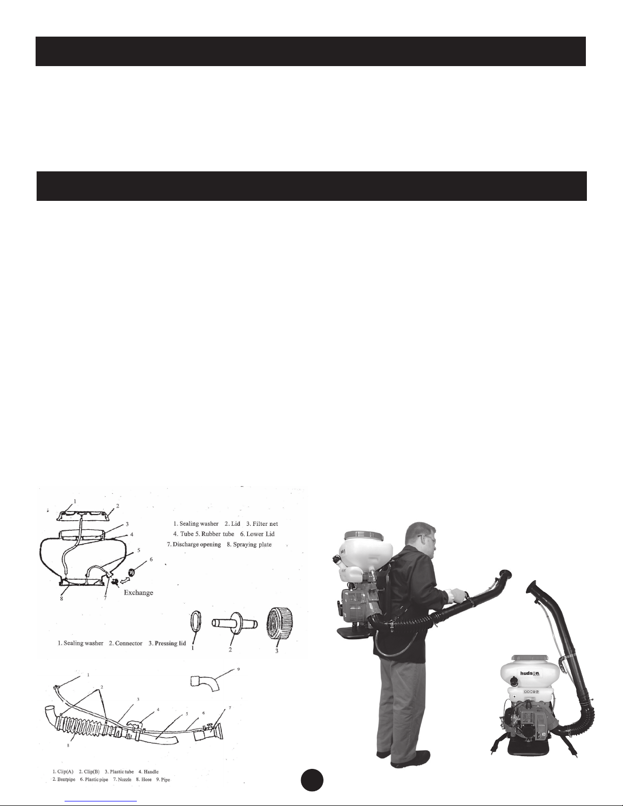
INITIAL ASSEMBLY
Assemble the larger end of the flexible hose to the engine elbow with a thumb clamp. The 16”
main tube comes next. The smooth end of the main tube with 4 internal ribs is inserted into
the small end of the flexible hose and secured with a thumb clamp. Slide the metal band of the
handle onto the main tube. Slide your arms through the shoulder straps and lift sprayer onto
your back. Adjust straps for comfort. Set the handle in a comfortable position and tighten the
screws.
ASSEMBLY FOR MIST BLOWER OPERATION
Changing spray plates.
Remove the filler cap from the tank. Remove the two 13mm hex nuts that hold the chemical
tank to the frame. Lift tank off the frame. Remove the dusting plate from frame and replace
with the spraying plate. There is an arrow molded on the spraying plate and it should point
toward the back of the engine.
Tank preparation.
Remove the tank plug and replace with hose connector, gasket, and retainer nut. Attach the
small black rubber hose to hose connector. The collared end of the hose should be attached
to the small pin on the spray plate. The open end of the hose should be placed over the spray
plate well. The clear air hose from the filler cap should be attached to the large barb on the
spray plate.
Hose preparation.
Loosen up the main tube thumb clamp. Insert the mounting plate of the fluid on/off switch
under the thumb clamp band. Retighten thumb clamp. Assemble the 17” bent discharge tube
to the main tube. Assemble the spray nozzle to the bent tube. Attach one end of the shorter
clear fluid hose to the inlet side of the on/off switch. Fasten with spring clamp. Attach the
other end to the hose connector on the tank. Fasten with spring clamp. Attach the longer clear
fluid hose to the outlet side of the on/off switch. Fasten with spring clamp. Attach the other
end to the spray nozzle. Fasten with the larger spring clamp from the tool kit.
3
Page 4

ASSEMBLY FOR DUSTING OPERATION
Changing spray plates.
Unscrew fill cover from tank. Remove the clamp and clear spray hose form the hose
connector on the outside of the tank. Remove the collared end of the small black rubber
hose from the spray plate. Remove the small black rubber hose, hose connector, gasket, and
retainer nut from tank. Remove the clear air hose from the filler cap. Remove the two 14mm
hex nuts that hold the chemical tank to the frame. Lift tank off the frame. Remove the spraying
plate from frame and replace with the dusting plate. The dusting plate has an off center
opening that should be aligned with the opening in the frame.
Tank preparation.
Screw tank plug onto side of tank.
Hose preparation.
Loosen up the main tube thumb clamp. Remove fluid hoses, on/off switch and spray nozzle as
a unit. The remaining accessory tubes can be fitted together as needed.
Anti-electrostatic installation.
Dusting or spreading granule chemical may cause a static electricity build-up. Some of
the factors that can cause static electricity are friction from the discharge tube, the kind of
chemical used, air temperature, humidity, etc.
Attach the insurance chain clip to the screw on the engine elbow. The chain should be allowed
to drag on the ground behind you. String the wire end along the discharge tube. Place the
wire at the 12 o’clock and 6 o’clock position on one end of the tube. Hold wire in place when
attaching the next tube.
4
Page 5

STARTING THE UNIT
Starting the unit
Check the following items before starting sprayer:
1). Check the spark plug gap. Should be set at 0.024”-0.028”
(0.6mm-0.7mm).
2). Spark plug should be tight in hole.
3). Air filter should be clean.
4). Check if engine rotates freely by pulling the starter 2-3 times.
Add fuel to gas tank. Engine must be off while fueling.
Fuel is leaded or unleaded gasoline mixed with 2-cycle engine
oil. Unit comes with a gas mix container. Fill gasoline to the lower
line on the container. Add the 2-cycle oil to the top line. Your fuel
mixture is correct. The engine is designed to run on 25:1 or 30:1
fuel mixture.
Add chemical to chemical tank
For liquid chemical, the fluid on/off switch must be in the off
position. Screw the fill cap on tightly.
For dusting chemical, the dust valve and fuel lever should be in the
bottom position. Clean off the tank threads first, and then screw
the fill cap on tightly. Keep people and pets away from open end of
hose.
Cold engine starting procedure.
1). Turn on the fuel switch.
2). Set the red handled throttle in the start position.
3). Open choke on the engine.
4). Pull recoil starter a few times. Do not let go of pull handle,
guide it back to starter. Letting go of the pull handle can cause
damage to the engine when the starter is recoiling.
5). Set choke to half and pull starter handle until engine fires.
6). After engine starts, fully open choke.
7). Let engine run for 2-3 minutes before misting or dusting
operation.
Warm engine starting procedure.
1). Leave choke fully open.
2). If the engine draws in too much fuel, close fuel lever. Pull
starter handle 5-6 times to clear the fuel. Open fuel lever. Resume
starting engine from step 5 of the cold engine starting procedure.
Speed adjustment.
If the engine bogs down too easily or does not stop with the
throttle at the lowest setting, the speed will need to be adjusted.
The speed control is located at the top of the carburetor.
1). Loosen the lock nut.
2). Turn the regulating screw counterclockwise to adjust velocity
up or clockwise to adjust velocity down.
3). Tighten the lock nut when satisfied with result.
5
Page 6

MISTING AND DUSTING OPERATION
Misting
Turn the numbered dial on top of the spray nozzle to regulate the amount of fluid to spray. The
indicator is above the hose barb on the spray nozzle.
Dusting.
Regulate the dust output by the black capped lever next to the throttle. There are 12 settings
for fine tuning the output. Wide open at the top, closed at the bottom. A 3 hole rocker arm,
located behind the backrest, can fine-tune the output even more. This unit was set up in the
middle hole or neutral position.
STORING SPRAYER AFTER USE
After spraying
1). Clean out any residual spray mixture or dust inside the chemical tank. Wash the tank inside
and outside with soap and water.
2). If unit was used for dusting, clean the dust gate.
3). Loosen chemical tank fill cap.
4). Run unit empty (or with water if used for misting) for 2-3 minutes after cleaning.
5). Do not store fuel in unit. It will turn to a varnish and gum up the carburetor. If unit will sit
idle for over a week, drain fuel or run unit dry.
6). Wash air filter in gasoline and soak in 25:1 gasoline:oil mixture.
7). The spark plug for this unit is 4106J. A Champion J8-C or equivalent spark plug can be
used. The recommended gap is 0.024”-0.028” (0.6mm-0.7mm).
8). For long term storage, cover the sprayer with a tarp. Keep unit in a dry, dust free place.
SAFETY
Read this manual carefully. Be sure you understand how to operate this sprayer properly before you use it.
Protective clothing
(1) Hat with brim
(2 Dirt/fog proof goggles
(3) Gauze face mask
(4) Long gloves
(5) Long sleeve shirt or coat
(6) Boots
People who should not use this sprayer
(1 Person not familiar with this sprayer
(2) Person on medication or overly tired
(3) Person after strenuous exercise
(4) Pregnant women or nursing mothers
Prevent fire
(1) Do not smoke by the sprayer
(2) Never refuel the sprayer when it is hot or running
(3) Never pour fuel on the sprayer.
If you do, clean it off
(4) Always tighten the fuel tank lid
(5) Always move the fuel container at least 10 feet
away from the sprayer before starting the engine
(6) Do not start or fuel sprayer around of
flammable materials
Starting engine safety
(1) Set the dust gate to the lowest position before starting engine.
Chemicals in tank will be jettisoned from the nozzle.
(2) Make sure the area in front of the nozzle is clear before starting the
engine. Even with the dust gate closed, residual dust in pipe can still
come out of the nozzle.
Misting / dusting
(1) Best spraying is done during cool weather with a little wind. For
example, spray in the early morning or late evening. This can reduce
the evaporation and chemical drift. It will improve the desired effect of
the sprayed chemical
(2) Operator should move with the wind
(3) If your mouth or eyes are splattered with chemicals, wash them with
clean water and then go see the doctor
(4) If you get a headache or experience dizziness while spraying, stop at
once and go see the doctor
(5) Follow the instructions and precautions on the chemical you are
working with
6
Page 7

TROUBLESHOOTING
7
Page 8

TROUBLE SHOOTING
Engine does not start or is difficult to start
Check for spark. The safest and easiest way is to use a spark tester.
PROBLEM CAUSE SOLUTION
NO SPARK
SPARK
PLUG
MAGNETO
FIRING DEVICE WET
CARBON BUILD UP
ON THE SPARK PLUG
THE CLEARANCE
BETWEEN POLES OF
SPARK PLUG IS TOO
BIG OR TOO SMALL
THE INSULATION OF
SPARK PLUG DAMAGED
POLES BURNED
WIRE COVERING IS
DAMAGED
INSULATION OF COIL IS
BAD
WIRE OF COIL IS
BROKEN
DRY IT OUT
CLEAN THE CARBON
ADJUST THE GAP TO
0.024" - 0.028"
(0.6 - 0.7 mm)
CHANGE SPARK PLUG
CHANGE SPARK PLUG
CHANGE OR REMEDY
REPLACE
REPLACE
NORMAL
SPARK
COMPRESSION
RATIO IS FINE
& FUELING
NORMALLY
FUELING IS
NORMAL BUT
COMPRESSING
RATIO IS BAD
NO FUELING
FROM
CARBURETOR
ELECTRONIC FIRING
DEVICE IS DAMAGES
EXCESSIVE FUEL
BAD QUALITY FUEL,
MIXED W/WATER OR
DIRTY
CYLINDER AND PISTON
RING WORE AND TORE
SPARK PLUG IS
LOOSEN
NO FUEL IN FUEL TANK
FILTER NET DIRTY
AIR HOLE OF FUEL
TANK IS BLOCKED
8
REPLACE
REDUCE THE FUEL
CHANGE THE FUEL
CHANGE CYLINDER
AND PISTON RING
TIGHTEN
FILL FUEL
CLEAN IT
CLEAN IT
 Loading...