

Hud-son OSCAR 18, OSCAR 228, 18 Owner's Manual
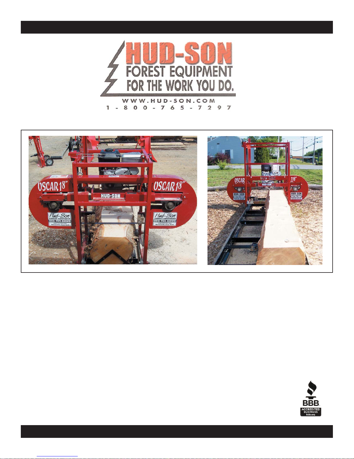
You have wisely selected a Hud-Son Portable Sawmill
Hud-Son Forest Equipment, Inc. 8201 State Rt. 12., PO Box 345 Barneveld, NY 13304
Phone: 1.800.765.SAWS • Fax: 315.896.2627 • e-mail info@hud-son.com
CONGRATULATIONS!
WWW.HUD-SON.COM
WWW.HUD-SON.COM
OSCAR 18 AND OSCAR 228 SAWMILL
OWNERS MANUAL
8201 STATE ROUTE 12 • BARNEVELD NY • 13304

Introduction
Purchaser Agreement
By accepting the delivery by Hud-Son Forest, you promise that you will not change,
modify, remove or make guards, shields, or any other safety feature, unusable or
unsafe. You are responsible to install any retro fit kits, from time to time, provided
to you by Hud-Son that will enhance or preserve the safe use of the product. If you
have any questions concerning the equipment you purchased from Hud-Son Forest
Equipment, about its safe use and/or maintenance, please go to our website
www.hud-son.com or contact your authorized Hud-Son Forest Equipment dealer.
Safety Guidelines
The reason for the Safety section is to inform the operators and maintenance personnel, the precautions that
should be taken while operating or servicing the Hud-Son Mills. These are a few basic safety guidelines to
follow, always use good judgment and have a safe attitude.
Please read and follow ALL the instructions in this manual before operating the Hud-Son Mill safely at all
times. These instructions were produced for your benefit. Your ability to understand and follow the instructions is essential for the safe operation of this product. Always call your servicing dealer if you are in doubt
before operation of any kind.
Please fill out the information for quick reference:
Dealer: ________________________________________Phone Number: _________________________
Address: _____________________________________________________________________________
Purchase Date: ______________________ Model: ___________________________________________
Serial Number: _________________________________________________
This manual is filled with the latest information and specifications at the time of publication. We have the
right to make changes as they are needed. Any of the changes in our product may cause a variation between
the illustrations and explanations in the manual and the item that you have purchased.

General Safety Procedures:
1) Always wear safety glasses, ear protection and gloves while operating or servicing the machine.
2) Keep all body parts and foreign objects away from all moving parts. Do not reach into the machine
while it is still operating. (Be Sure The Machine Is OFF.)
3) Do not attempt to override any safety features on the machine.
4) Inspect the machine before every use for wear, damage and correct function. If the machine has been
damaged or is not running correctly, DO NOT attempt to operate the machine. Repair or replace all
parts when necessary.
5) Do not wear loose clothing or jewelry while operating or servicing the machine.
6) All replacement parts should be of the same specifications and operation as the original parts of the
machine.
7) All guards and covers must be in place befor
e operating the machine.
8) Before starting the machine, be sure that it is set up properly.
9) DO NOT operate or service any machinery while under the influence of drugs or alcohol, while tired
or if you are unable to control your movements.
10) All worn or damaged decals should be replaced.
11) Any modifications to the product require written approval from Hud-Son Forest Equipment.
12) The processor should only be used when it is on level, stable ground.
Electric Engine Safety Procedures:
Lockout/Tagout is the practice and procedure to safeguard the employees from unexpected energy, start-up
of machinery/equipment or the release of hazardous energy during servicing or maintenance procedures.
A designated individual will be required to turn off and disconnect the machinery/equipment from the energy source before any procedures are preformed. The authorized employee will need to lockout/tagout the
machine/equipment energy device that will prevent the release of hazardous energy. You will need to take
action to verify that the energy had been isolated effectively.

WARNING: ONLY AUTHORIZED PERSONNEL ARE TO PERFORM
PROCEDURES LISTED BELOW
1. Inform any affected personnel of lock out/tag out equipment
2. Turn main electrical breaker into off position
3. Insert proper lock out device in main shut off and apply lock.
4. Keys are to be kept in your control until repair or maintenance is complete
5. Test to be certain that the equipment is off and has no stored energy
6. Perform repair or maintenance tasks.
7. Check control panel switches to be sure they are in the off position
8. Remove any tools or other objects used in repair or maintenance from equipment
9. Clear any other personnel from area
10. Remove lock out device
11. Turn main shut off to the on position
12. Test equipment functions
13. Inform affected personnel that servicing and maintenance is complete
14. Return lock out device and keys to storage box
Example of Lockout/Tagout Safety kit
(This is Not provided by Hud-Son Forest Equipment, you will need to purchase this type of system)

Affected Employee Customer who is required to operate the equipment/machine on which
service or maintenance is being performed.
Authorized Employee Person who performs the tagout system procedures on equipment/machines
to perform the service/maintenance on that equipment/machine.
Energy Source Any source of electrical, mechanical, hydraulic, pneumatic, chemical,
thermal or other energy source.
Lockout Placement of lockout device on any energy isolating source to ensure the
device cannot be turned on or operated. Procedure stops must be followed.
Servicing/Maintenance This can include the set-up, adjusting, inspecting, modifying or servicing
the equipment/machines. It may also be the lubrication, cleaning or fixing
the unit. This should include anything where the customer may be exposed
to the unexpected energy, start-up of equipment.
Tagout Placement of a tagout device on an energy-isolating device to ensure the
equipment/machine may not be operated until the tag device is removed.
Term Description
The safety rules are made for the benefit of the persons operating and servicing the machine,
to prevent injury to oneself or others. Please review all setup and operating procedures
before attempting to run the machine, whether covered in this manual or not,
to ensure the safest operation of this product.
Hud-Son Forest Equipment is not liable for damage to property or personal injury due to unsafe use of the
product. Hud-Son Forest Equipment is not liable for damage to property or personal injury due to the failure
of any person and/or operator to follow the instructions and recommendations set forth in this manual or any
other instructions or recommendations contained in other literature issued by other vendor manuals in the
owner's kit.
Product Safety Decals
The decals on the following page are used on the Hud-Son Saw Mills to identify warnings and prohibited
actions. It is very important that you understand the meaning of the decals, for your safety and the safety of
others. Decals are to be replaced if worn or illegible.
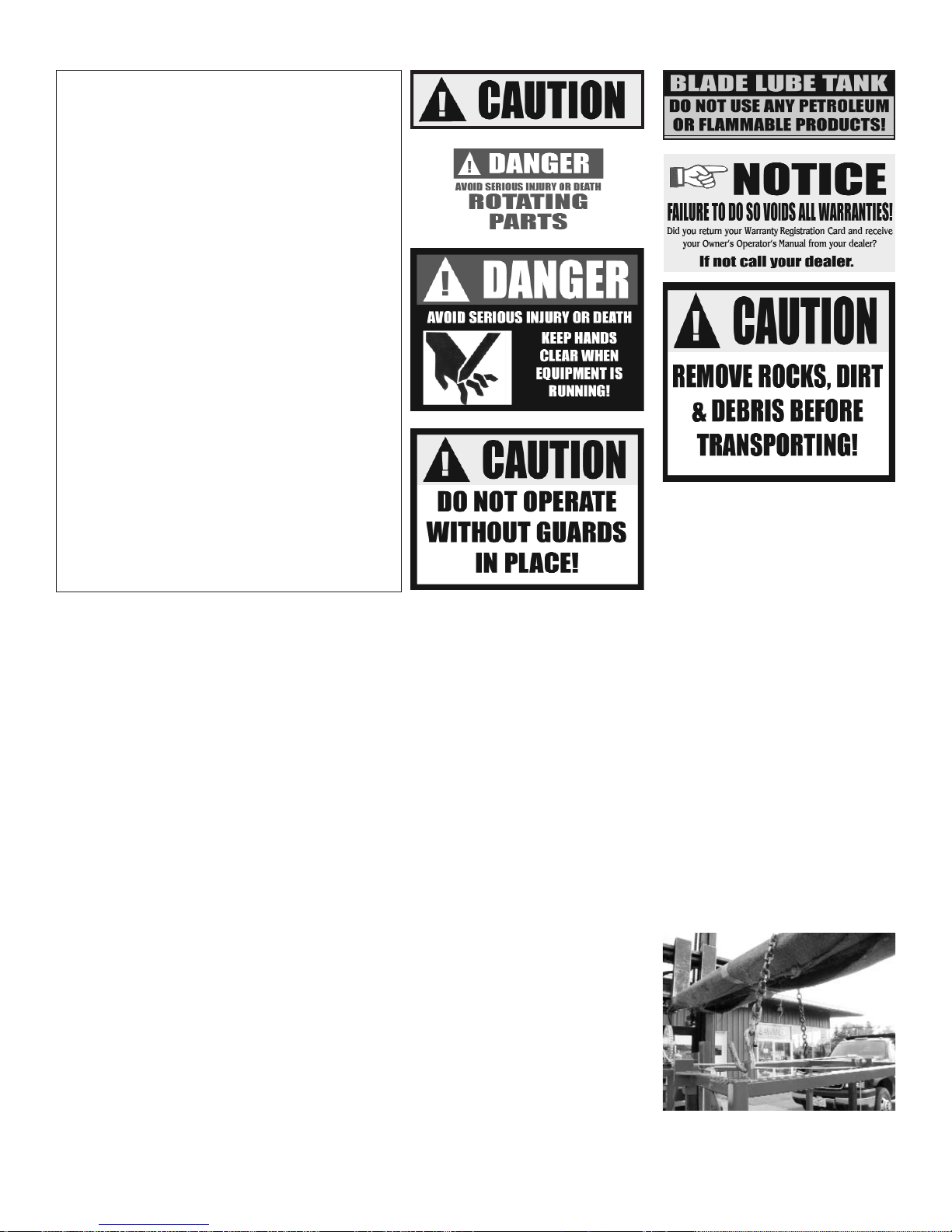
CAUTION - Be EXTRA careful around
these areas, unsafe practices may cause personnel injury or damage.
DANGER - Be careful around any rotating
parts, they may cause personnel injury or damage.
DANGER - Be sure to be very cautious and
alert, these areas may cause personnel injury or
damage.
CAUTION - Operating equipment without
guards may cause personnel injury or damage.
BLADE LUBE TANK - be sure to use the
correct lubrication, if incorrect lube is used it
may cause personnel injury or damage.
NOTICE - Please remember to send in warranty card and information.
CAUTION - All debris needs to be removed
from machine be fore transporting, failure to so
may cause personnel injury or damage.
Set-Up and Operation
Any Hud-Son Saw Mill requires a minimal amount of set-up before operation.
Be sure to wear safety glasses, gloves and ear protection at all times
while operating any piece of Hud-Son equipment.
Receiving and Unit Inspection
1) Upon receiving your unit do a walk around and visual inspection of the unit. Make note of any damage and contact us immediately with any issue you may have.
Note: All equipment is assembled, tested and inspected before shipping. Damage can occur during transit,
which could cause the unit to not operate correctly.
Unpacking Unit
1) Flat bed trailer delivery: remove straps or chains securing the unit.
2) Remove lag screws and strapping that secures the machine to the skid.
Moving the Unit
(Forklift is needed for track units)
1) Machine needs to be lifted at the lift point, see picture for points.
a. Use a safety devise for lifting to avoid any damage/injury.
2) Move unit to operator's site, lower unit and remove unit from forks.

Start Engine Procedure
1) Summer Use: Be sure to let the unit idle for at least 5 minutes before any use.
2) Winter Use: Be sure to let the unit idle for at least 15 minutes before any use.
3) If the unit has been sitting for a period of time, allow the unit to run long enough to have the oil do
a complete circulation before use.
Steps for Setting-Up the Hud-Son Saw Mill
A. Machine Set-Up (ground track unit)
a. For best results and easier set-up, the mill location should be level and free of obstructions.
b. A level cement pad is the best option, but square timbers also work well. You will need to support the
track at each joint and under each cross member.
c. You will need to be sure that the mill is level from front to back and side to side.
The better the mill is supported the better the mill work.
d. There should be a 4 ft. clear work area around the entire mill.
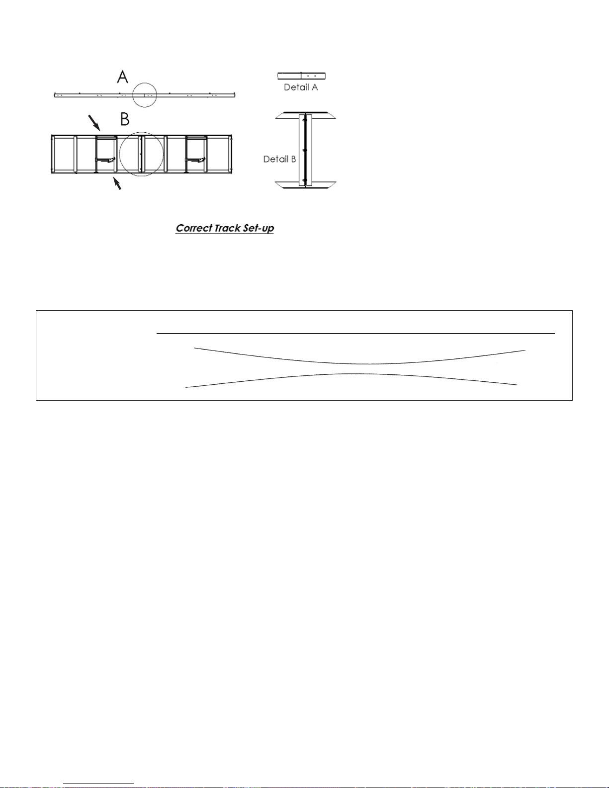
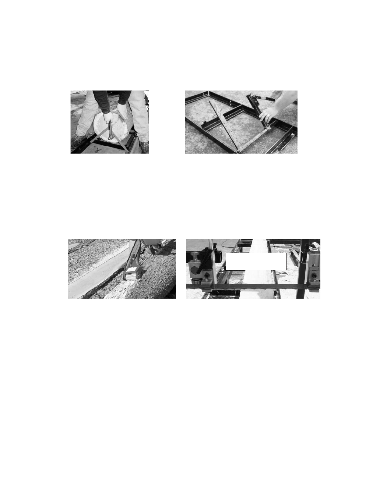
B. Track Assembly
a. Dogs needs to facing in the same direction, the moveable dogs need to be on the same side of the
track which is on the operator's side of the mill head.
b. There are additional holes in the track so that the dogs can be moved to different positions.
c. The tracks are bolted together using bolt and nuts. The Oscar 18 and 228 mills will have 2 bolt/nuts:
the Oscar 230/236 and 52 mills will have 3 bolts/nuts. Line up the tracks so that the center holes align. Using
the provided bolts put them through the holes and finger tighten the nuts. Adjust the track height so that the 2
pieces of track meet flush and level. Work one side then the other, once level has been achieved, check the
track to see if it aligns vertically. If the track is not aligned correctly use a hammer to tap it into position. Once
this is accomplished tighten the bolts securely.
Moveable Dogs -
On one side
Track on level ground,
free of obstructions
Bolted together Track - Flush & Level
Track Stops
Before operating the Hud-Son Saw Mill the following procedures need to be performed:
1) Check oil and fuel levels
2) Check blade lubrication and hydraulic levels (if applicable)
2-A - Check blade lubrication and hydraulic levels.
DO NOT USE: petroleum products, petroleum based products, flammable products, a vegetable oil based
product. The above products mixed with water or straight will cause damage to your mill. The fluid will be
slippery between the blade and wheel belting causing blade to come off.
DO USE: In The Summer Months tap water. If there is a problem with pitch build up on the blade, add 1 oz. of
dish soap or pinesol to 1 gallon of tap water. This will help keep the blade clean and less heat.
In the Winter Months water will freeze in the lube tank. Use regular windshield washer fluid
(usually blue in color) If there is a pitch build up problem add the 1 oz. of dish soap or pinesol. Adjustment:
Before starting the engine, adjust the flow of lube to the blade by adjusting the flow shut off valve so there is a
constant drip. If more lube is necessary, continue to adjust the valve until the desired flow is acquired.
3) Be sure the blade is sharp and tight
4) Be sure all levers and switches are in the neutral/center position before starting the engine
(if applicable)
5) Be sure all persons are clear of the equipment
6) Make sure the unit is level and stable
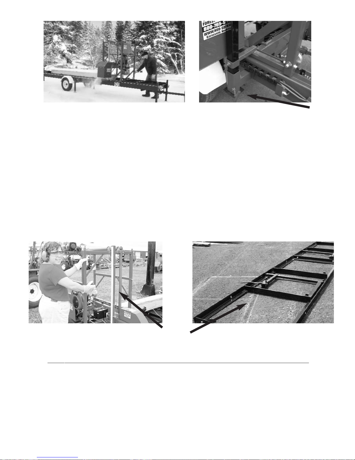
Set-Up and Operation
d.The track comes with 4 track stop
assemblies. The assemblies consist of
the track stop, bolt and nut.
Place the tracks stops in the 4 end corners of the track. Place them on the
inside of the track and use
the nut and bolt to secure them into
place. They are placed at an angle
over the track, thus blocking
any further travel of the mill head.
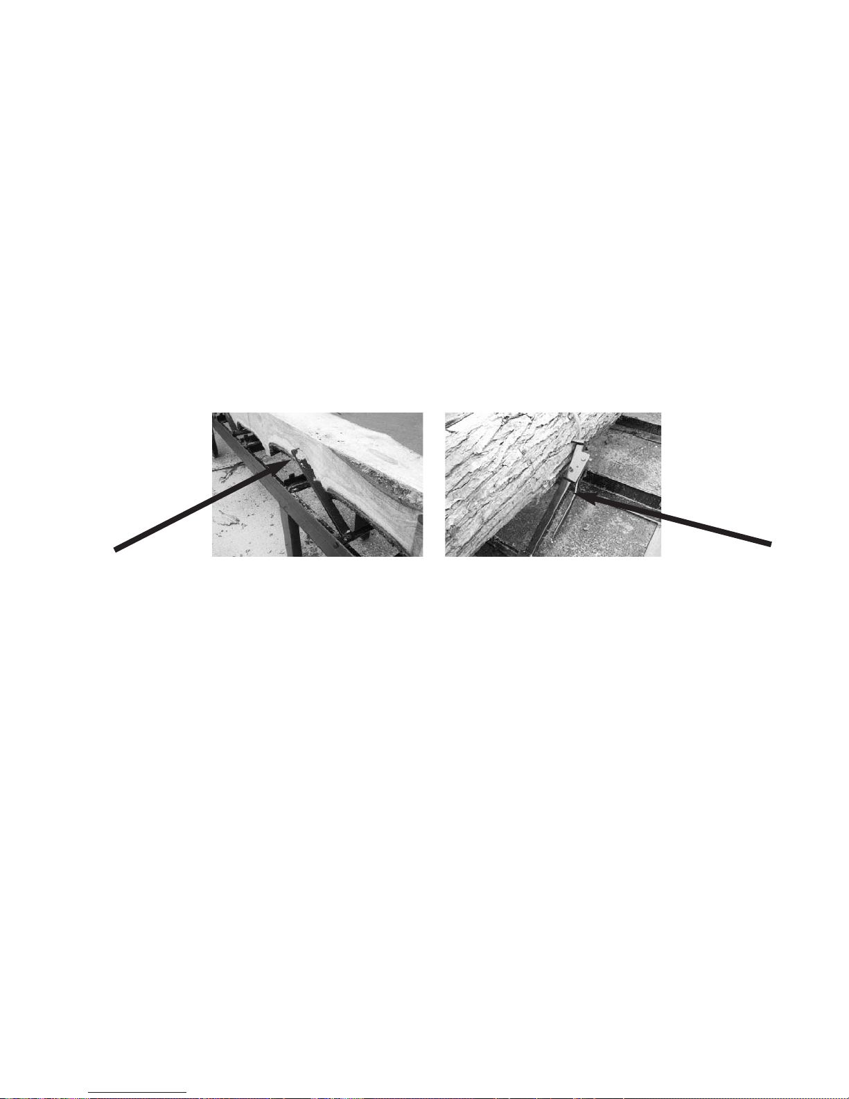
e. Sawing a board accurately, the track needs to straight or flat. To obtain this, us a string tied from end
to end or a level. If the track/trailer has a crown or dip, you will not be able to saw a straight board.
Correct Track
Incorrect
Dipped Track
C. Machine Set-Up (trailer unit)
(20' or 24' Torsion Axle Trailers, (230, 236, 56, Farm Boss, H360, H2HG))
a. Set-up area should be relatively level and clear of debris. The head will need to roll down the track so
be sure the area is free of obstructions.
b. Lower the trailer jack and raise the jack until the coupler is free of the hitch. Once this is done remove
the unit from the vehicle. Using the "T" handles, loosen the bolts and lower the front 2 legs.
c. Do the same to lower back 2 legs, and level the trailer.
d. Lower the center 2 legs last, the track should already be level.
e. On the 18/228 models, you will need to unbolt the head from the track. The travel bolts are located
behind your guide arms at the base of the mill head.
f. Once the head is unbolted from travel position, roll it down the track to be sure it is level. If your head
rolls on its own you will need to adjust your leveling legs. Return the head to the center of the trailer
and re-bolt or raise the center legs to lock head into place. Once the head is secure you can reset the
leveling legs.
**Always secure the head before re-leveling the trailer***
g. Once the trailer is level, the head should not roll on its own. If your trailer is not level, it will not saw
your boards correctly. Refer to pervious instructions for proper set-up.
Squaring Pin
Moveable Log Dog
Operator’s
Side
D. Setting Head on Track (If Applicable) Ground Models
Once your track is level, you are ready to set the head on the track. Once again, be sure the area is still
free and clear of obstructions. You will want the head to roll freely down the track.
a. Install the head with operator's side on the same side as the moveable dog. The discharge side is the
side with the squaring pins.
b. Raise the head 3 inches and roll from one end to the other. The head should roll smoothly along the
track. If the head "thumps" when it passes over the track joint, check to make sure the tracks are level.
Re-level the track and try rolling the head again. Also be sure to watch the track as you roll the head,
if the track moves, you will need to support the track in that area.
Correct trailer set up - All legs are level; head should not
move on its own.
Correct head placement; Operators side is on side with the
scale stick.
Legs are locked into place,
head will not move.
Squaring arm on right, adjustable dog on left.
d) Set the guide bracket so that the back bearing is on the same plane as the blade, so that if the blade were
to wander back it would hit the back bearing evenly across the middle of the roller. If the bearing needs to be
adjusted up or down, loosen the bolt that holds it to the guide bracket and space it in either direction using the
washers that are on either side of the bearing.
e) Once the bearing is set, position the guide bracket so that the bearing is spaced 1/8" behind the back of
the blade. Once the bearing is in position, tighten the bolt on the top of the guide bracket into place. Be sure
guide is 90
o
to the blade.
ALWAYS WEAR GLOVES AND EYE PROTECTION WHEN OPERATING SAWMILL

f) The guide shoes are to be set using a sheet of paper to gauge the spacing. Place the paper between the
shoe and the blade, slide the shoe so that it is pinching the paper, and tighten the bolt so that the shoe is set in
place. Do the same on the bottom of the blade. Note that you do not want the shoes to be pinching the blade so
hard that they are prohibiting blade travel.
g) Make sure that all nuts and bolts are tightened firmly.
Pictured is a close-up of the guide
It shows all the bolts and bearings that can
possibly be adjusted. Note how the teeth are
outside of the guide.
Set-Up and Operation
E. Tensioning the Blade on all Models
NEVER tension your blade with the engine running. Your mill is shipped to you without any tension on the
blade. If there is tension left on the blade for a period of time, it can cause flat spots in the belt.
This will cause the blade to fall off the wheel. Always remember to de-tension your blade when you
are done sawing for the day.
a. To tension the blade, remove the guards and loosen/tighten the nut on the tensioning bolt.
b. Turn the adjusting bolt or stud, clockwise until 30-35 pounds of torque is achieved. The recommended
tool for this is a torque wrench. By hand, rotate blade 3-4 full revolutions; this centers the blade on the
wheels.
c. With gloves on, pull up on the blade at the center guard. Allow for no more than a ¼" movement up or
down on the blade.
d. Blade guides must not be so tight they cause the blade to move up or down.
e. Perform a simple test call the "Flutter" test. Put the guards on and then run the engine at full RPM's
(be sure the blade is not in a cut during this test) and watch the blade under the blade guard. The blade
must run straight, if it does not, shut the engine down and apply more tension. Keep in mind that over
tensioning will also cause the blade to flutter. You should have attained proper tension around 30-35
pounds.
f. A tensioned blade should come off the bottom of the band wheel and run straight across to the other
band wheel, so there is NO sag in the blade between the two wheels.
Tension nut for
smaller units (O18/228)
F. Setting Logs
Once the track is set, the head is in place and the blade is tensioned correctly, you are almost ready to cut.
a. Place the log determined by the mills size, on the center of the track. Using the log dogs secure the log
to the track. Be sure to dog the log high enough (1/2" way up the log) to ensure the log does not
move. If the log is too big for the log dog to hold in place, but your sawmill head still rolls
unobstructed use the "Cheater" to hold it. (For use on the 18/228 only).
G. Getting Ready to Cut
Now is the time to debark or clean your log. This can be achieved by the simple chainsaw attachment,
called a Log Debarker (available through Hud-Son Forest Equipment Inc.) or you can pressure wash or
use whatever method available to remove any mud or bark from the logs. By debarking and cleaning your
log it will extend the life of your blade.
a. Adjust the Hud-Son guides so that they are slightly (no more than 2 inches) wider than the maximum
width of the log.
(Note: as you cut slabs, boards or squares you may need to adjust the guide to ensure the best performance
and quality cuts)
b. Find the top of the log with the blade. Remember, that you may have cheaters in place so be sure these
are clear when making the first cut. You will be removing the top potion of the log. (top slab)
c. On the manual lift models, crank your head down to the desired height and click up one notch to set
the head. Make sure your blade will clear your dog assembly.
d. Start your engine, let it idle for at least 5 minutes. (Refer to the engine manual for proper engine
maintenance)
e. With the engine in idle position, increase the throttle to start the blade. Sawing should always be done
with the engine in full throttle.
f. Gently push the saw head through the log, pushing on the head frame. If the engine starts to labor, you
are going to fast, slow down. Go slow through burls and knots as the engine may bog down through
these parts of a log.
Cheater
Squaring Arm
Adjustable Dog
Debark the
log.
Guide location
- log width
g. When you are at the end of the log, power down the engine, crank the head up so that will clear the log
and roll back to the front of the log. For ease of operation, put the slabs on the operator's side of the
mill, this way you will not have to dig through sawdust for your lumber.
h. You now have a flat surface on top of your log, remove the cheaters (if applicable), you will no longer
need them, as long as the log dogs will hold the log in place.
i. Set your log dog assembly so that they are standing in the track. Turn the cut side of the log, using a
cant hook, ¼ of a turn. The flat side must be flush against the squaring pin to assure a square cant.
j. Adjust the log dog at an angle to the track so that the blade can pass over the top, but so that the dogs
are effective in securing the log.
k. Once again, increase the engine throttle to start the blade, and saw another slab. You will repeat step
(I) until your log is squared into a cant. You may now saw your dimensional lumber.
l. Steps (I-K) may not be applicable if a cant is not desired.
Place flat side, flush
against squaring pin to
ensure a square cant.
Adjustable dog, set
at an angle so that log
can be sawed without
interference.
H. Cutting Dimensional Lumber
You can cut down to a 1" thick bottom board. To achieve this you will use the moveable side of the dog and
the short squaring pins welded in the track.
a. You will need to determine the size lumber that can be cut and how many, then using the scale start
sawing your lumber. Lower the blade to desired thickness and saw your board. Repeat this process
unit all lumber is cut.
b. You may need to turn your cant to make the desired lumber.
I. Replacing the Blade
No matter how well you care for your blade, they will dull after time and need to be changed. Longevity of
your blade depends on how well you maintain it.
a. The engine needs to be stopped, turned off and the key removed, this ensures that the engine can not be
accidentally turned back on. On engines with manual start, you will need to remove the spark plug
wire prior to servicing. On electric motors a lockout/tagout should be used.
b. Loosen and remove wing nuts so you can remove the outside and center guards on all models.
c. Loosen band blade tensioner bolt until adjusting bolt is flush with threaded plate.
 Loading...